Si deseas distinguir tus productos, servicios o ambos de los de otra empresa, es posible que necesites una marca o nombre comercial. Descubre qué son, en qué consiste su procedimiento de registro y qué implica.

Información sobre los plazos de presentación de solicitudes de transformación de marcas de la Unión Europea en marca nacional española. Más información


Si tienes un nuevo dispositivo, producto o procedimiento que resuelva un problema técnico o tenga una ventaja práctica, existen distintas formas de protegerlo en España y en otros países. Descubre cómo hacerlo.

¿Tu innovación reside en la estética, la ornamentación o la apariencia de tu producto? Protégela mediante un diseño industrial. Descubre qué derechos confiere el registro y cómo realizar la tramitación.

Las indicaciones geográficas protegen el nombre de un producto originario de una zona geográfica, a la cual le debe una determinada calidad, reputación u otra característica. Descubre qué son, en qué consiste su procedimiento de registro y qué beneficios conceden.

Las patentes publicadas en todo el mundo son una valiosa fuente de información científica, técnica y comercial.

Si eres emprendedor/a o una empresa y quieres potenciar y mejorar la rentabilidad de tu negocio protegiendo de forma adecuada los activos intangibles de tu organización, en este espacio encontrarás lo necesario.


 161
resultados
161
resultados
 Última actualización
15/09/2026 [08:03:00]
Última actualización
15/09/2026 [08:03:00]


 Resultados 100 a 125 de 161

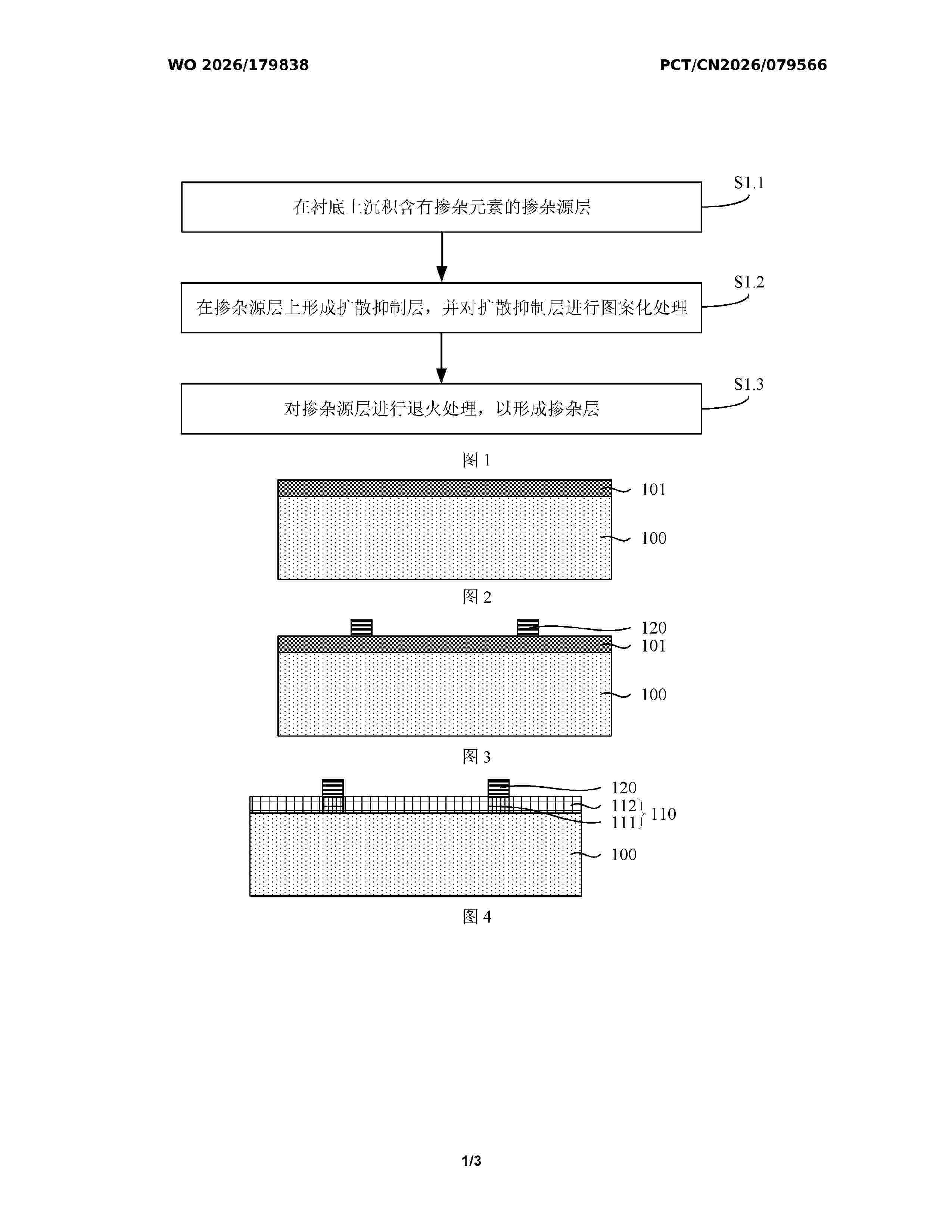
Resumen de: WO2026179838A1
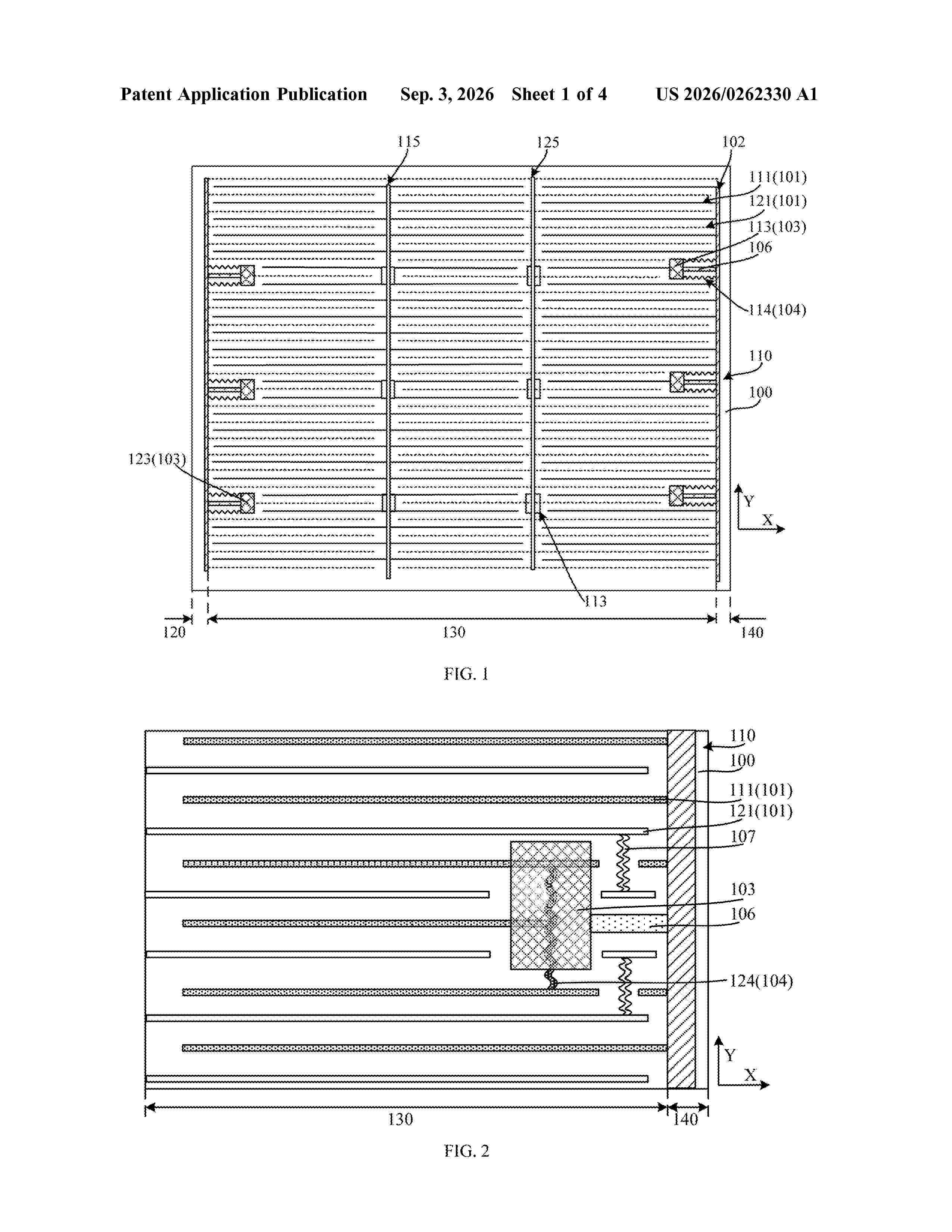
A preparation method for a doped layer (110), a preparation method for a solar cell, and a solar cell. The preparation method for a doped layer comprises the following steps: depositing a doping source layer (101) containing a doping element on a substrate (100); forming a diffusion suppressing layer (120) on the doping source layer, and patterning the diffusion suppressing layer to expose part of the doping source layer; and annealing the doping source layer to form a doped layer. The preparation method for a doped layer allows for formation of a selectively heavily doped region (111). The preparation method for a doped layer avoids the formation approach of laser heavy doping in conventional technology, without the need for using laser to direct melt a doped layer, thereby avoiding the problem of thermal damage.

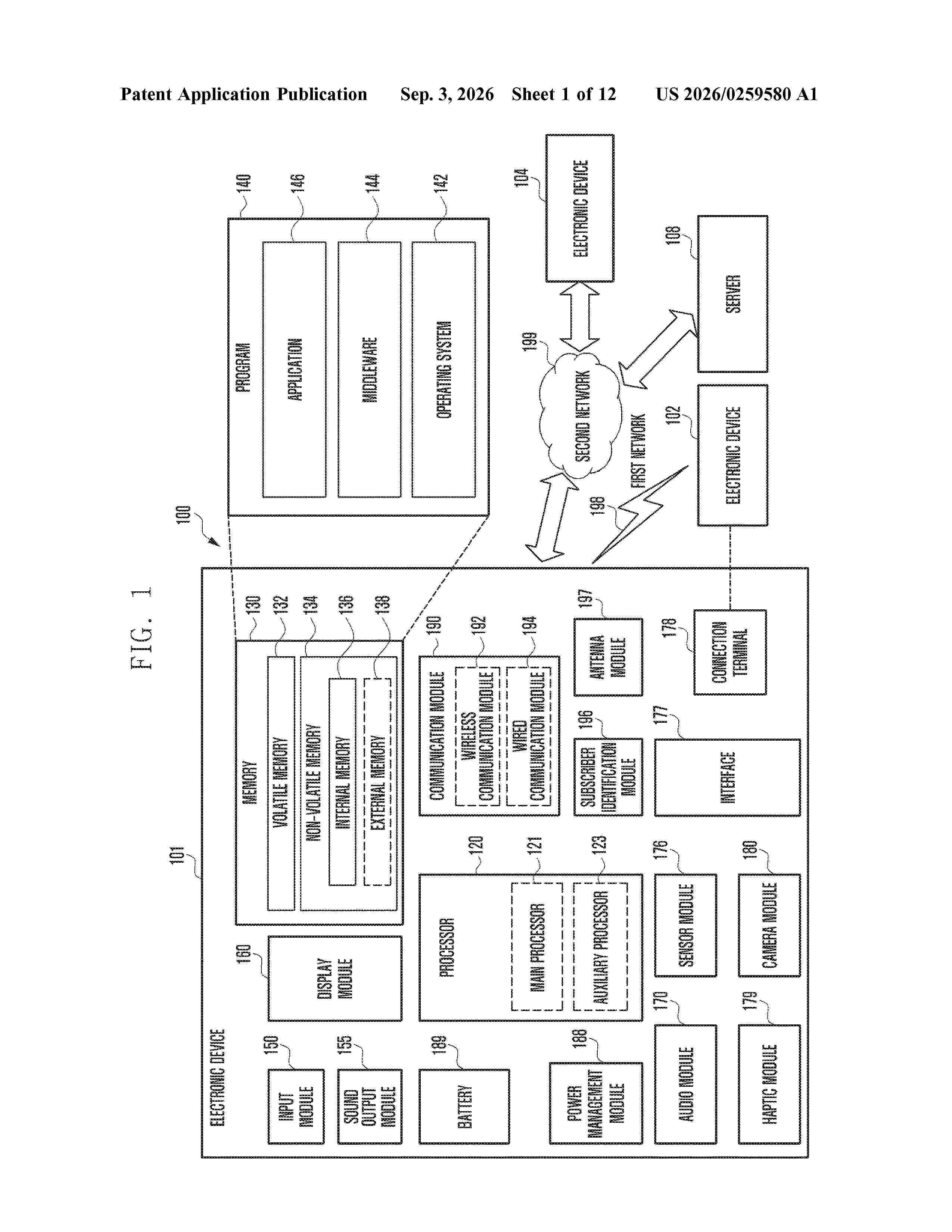
Resumen de: US20260259580A1
0000 An electronic device is provided. The electronic device includes a first housing having a fastening part provided at a lower end thereof, a ring-shaped second housing having an accommodation part provided at an upper end thereof, the accommodation part configured to detachably accommodate the fastening part of the first housing to allow the first housing to move in response to a downward pressing input applied to the first housing, memory, including one or more storage media, storing instructions, and a processor communicatively coupled to the memory, the processor provided in the second housing, wherein the accommodation part includes a fixing member configured to mount the fastening part to the accommodation part, and a switch button installed at a lower end of the accommodation part, and wherein the instructions, when executed by the processor, cause the electronic device to perform a specified function, based on an on/off pattern signal of the switch button generated in response to the movement of the first housing due to the pressing input applied to the first housing.
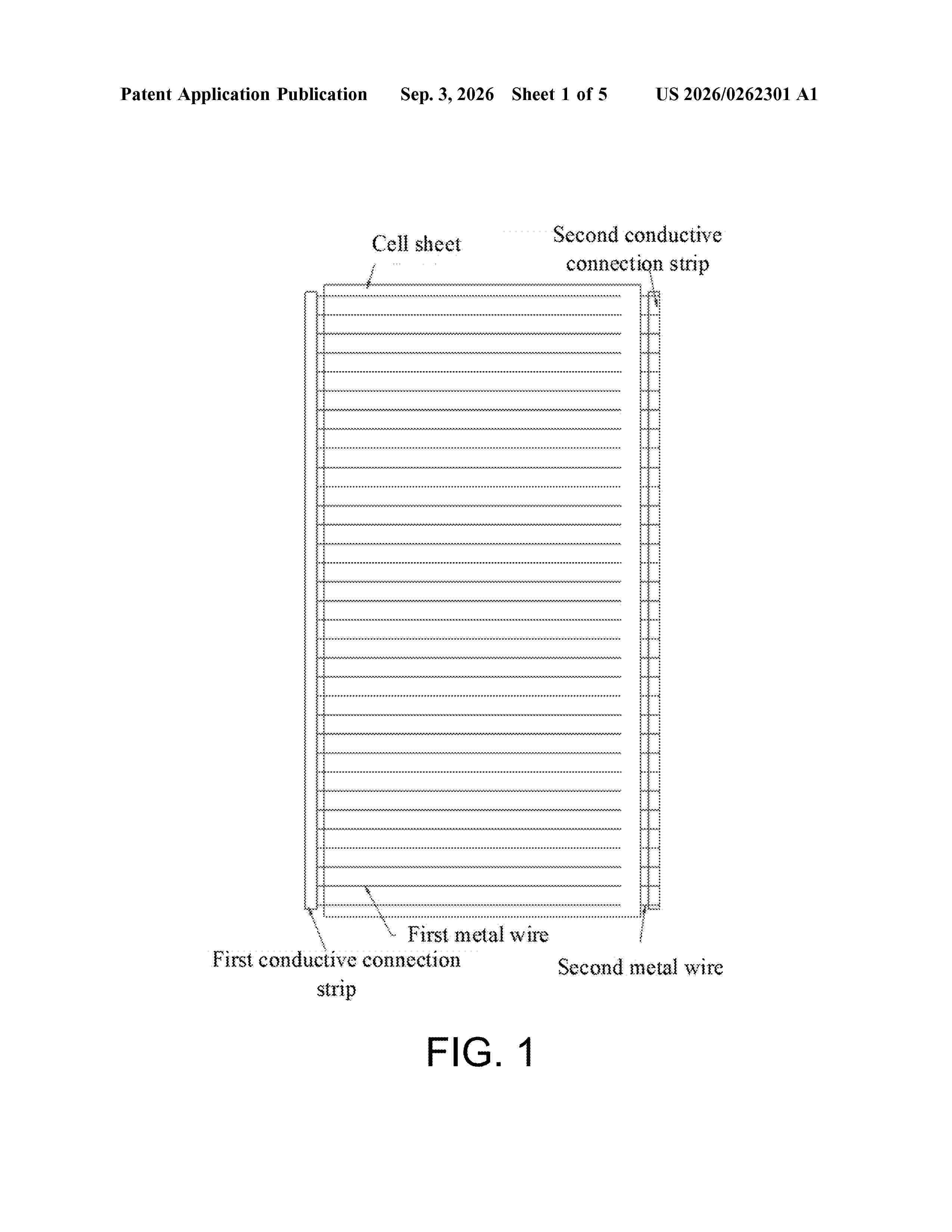
Resumen de: US20260262301A1
Provided is a photovoltaic cell unit, including conductive connection strips respectively arranged on two sides of a cell sheet and parallel to each other. A front surface and a back surface of the cell sheet are respectively connected to the conductive connection strips through a plurality of metal wires. Also provided are two methods for manufacturing a photovoltaic module. The present disclosure can reduce the consumption of silver on the surface of the cell sheet, alleviate the shading of light by the metal wires, and speed up the manufacturing of photovoltaic modules. According to the present disclosure, a plurality of cell sheets can be placed simultaneously during cell sheet placement, thereby increasing the cell sheet placement speed.
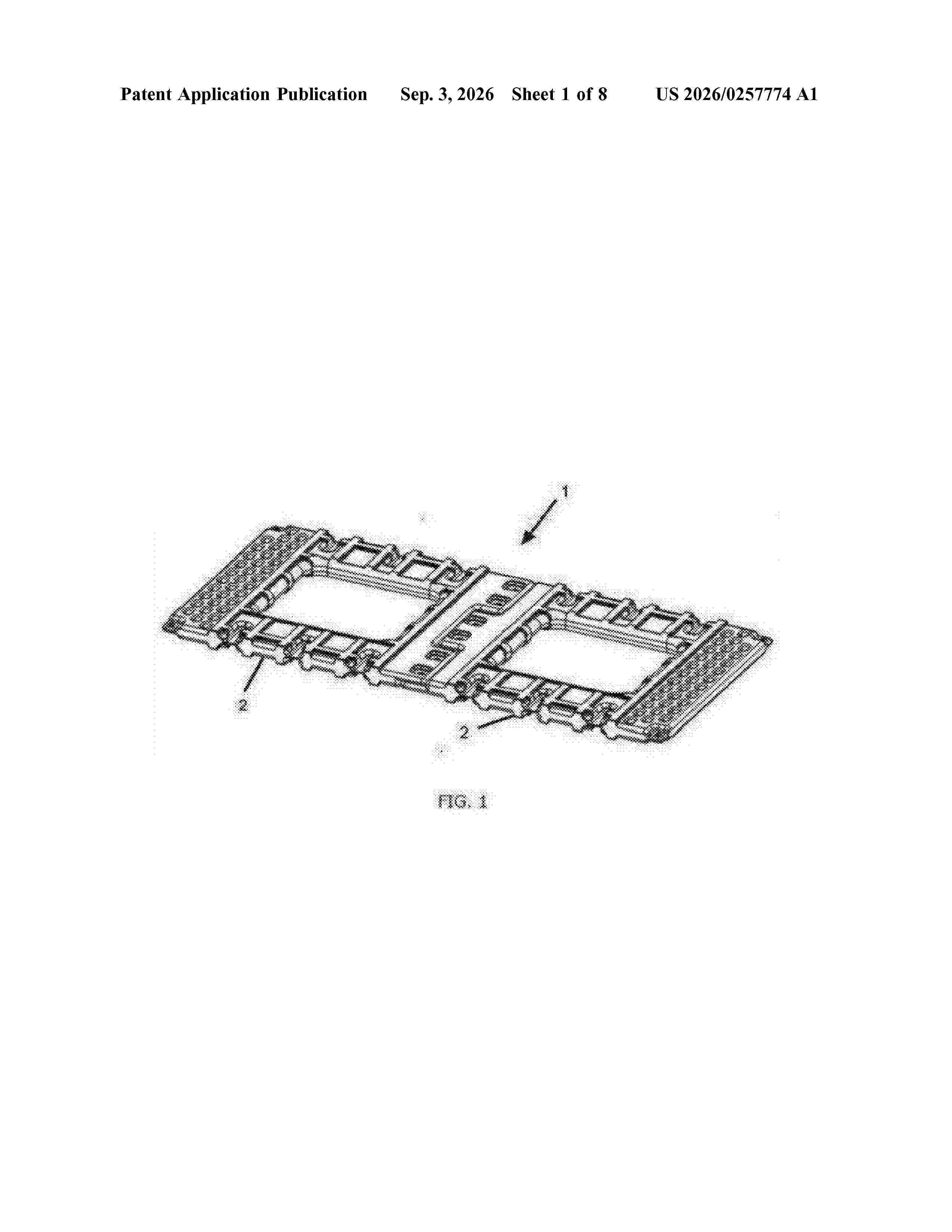
Resumen de: US20260257774A1
A floating system for photovoltaic panels, includes two assembled floats, each float having a substantially rectangular shape. Each float includes: several flanges protruding from one side of the float, two of them being end flanges and one being a central flange, the central flange being at a different level than the other two, and each flange having at least one through hole, a pair of first slits with a through hole, each of them on a corner of the side opposite to the side comprising the flanges, the side comprising the slits being adjacent to a side frame area, and several second recesses on the other two sides of the contour of the float, so that the floats are assembled by the flanges and by means of fastening means which pass through the through holes in the flanges to form the floating system.
Resumen de: US20260257775A1
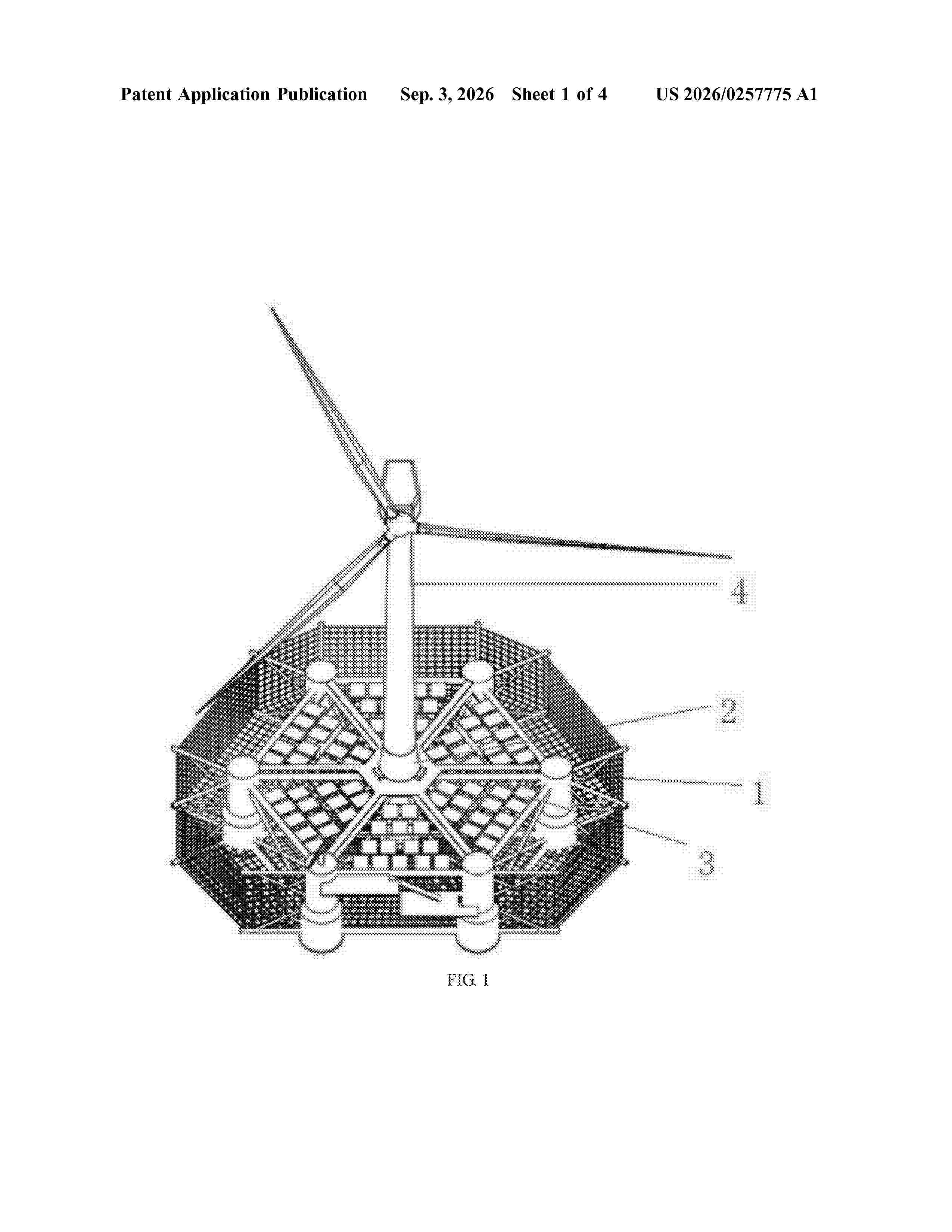
0000 A multifunctional integrated platform, includes a wind turbine, a photovoltaic power generation system, a floating body, and a net cage. The wind turbine, the photovoltaic power generation system and the net cage are all mounted on the floating body. The wind turbine is configured to perform wind power generation, and the photovoltaic power generation system is configured to perform photovoltaic power generation.
Resumen de: US20260262325A1
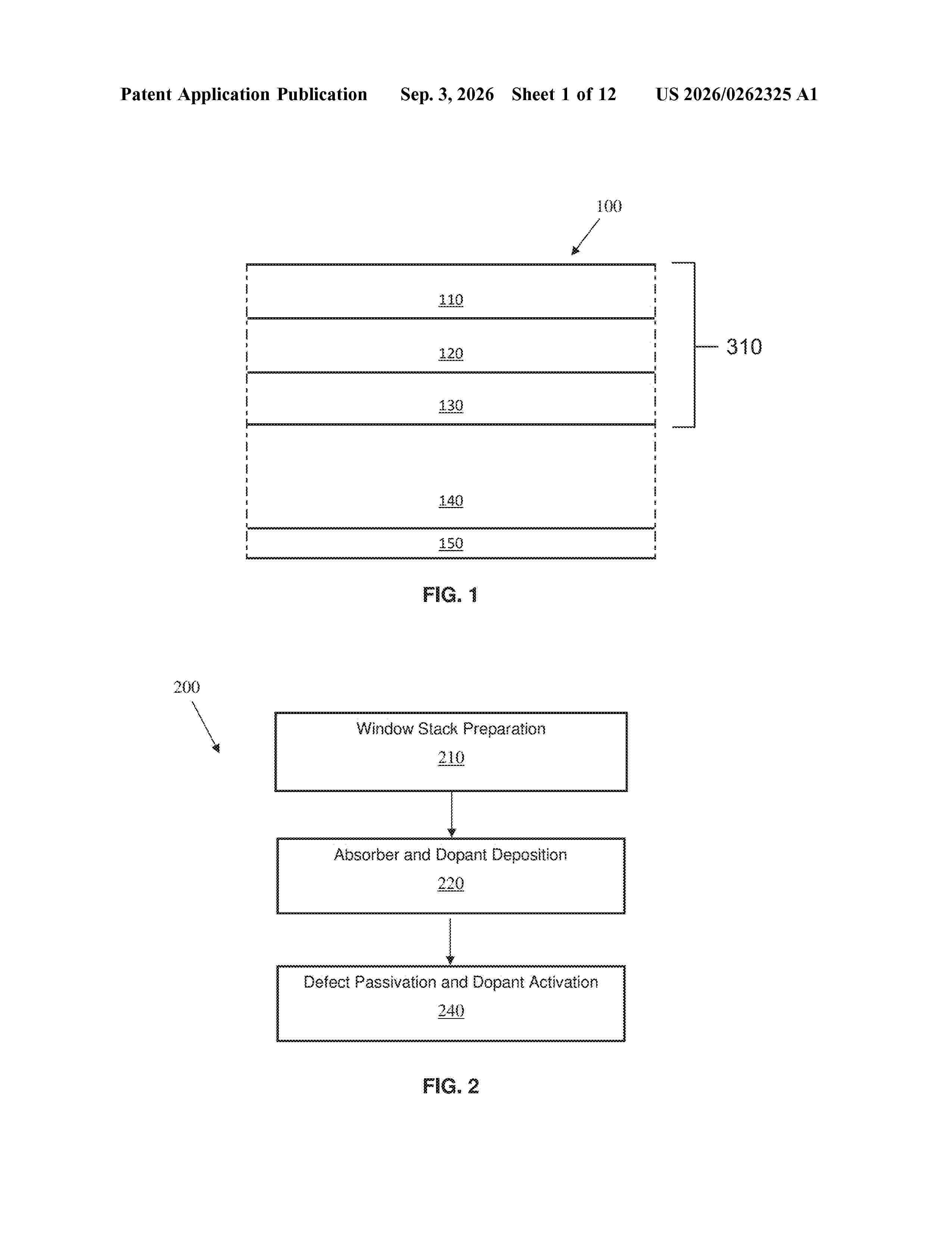
0000 Provided are structures and methods for doping polycrystalline thin film semiconductor materials in photovoltaic devices. Embodiments include methods for forming and treating a photovoltaic semiconductor absorber layer.
Resumen de: US20260262433A1
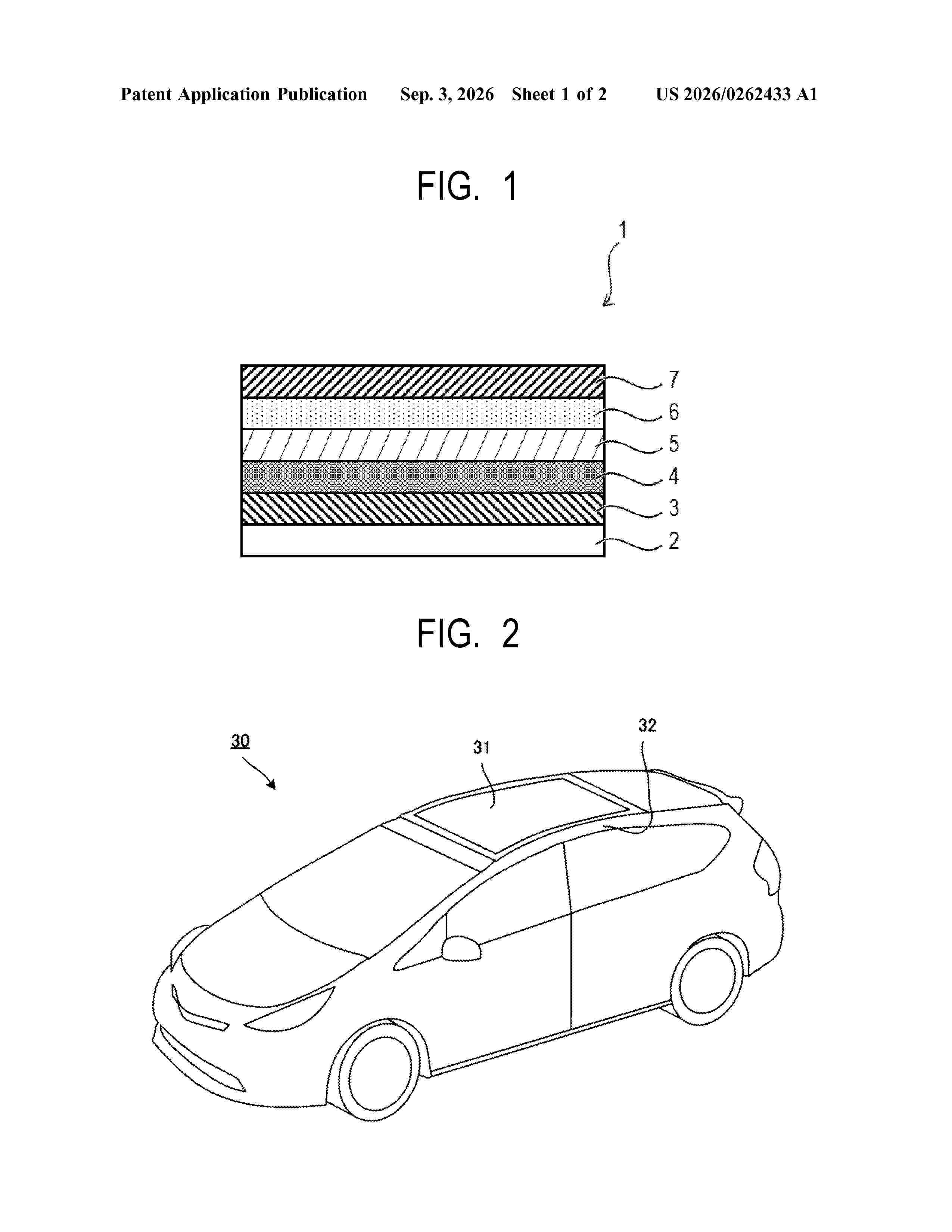
To provide a photoelectric conversion element that achieves both mass productivity and the uniformity of photoelectric conversion efficiency, provided is a method of producing a photoelectric conversion element, the method including: a step (A) of forming a photoelectric conversion layer containing a crystal having a perovskite structure by using a large-area film formation method; and a step (B) of forming a charge-transporting layer by applying a paint for a charge-transporting layer onto the surface of the photoelectric conversion layer and then drying the paint, wherein the paint for a charge-transporting layer contains a charge-transporting particle and an insulating resin.
Resumen de: US20260261228A1
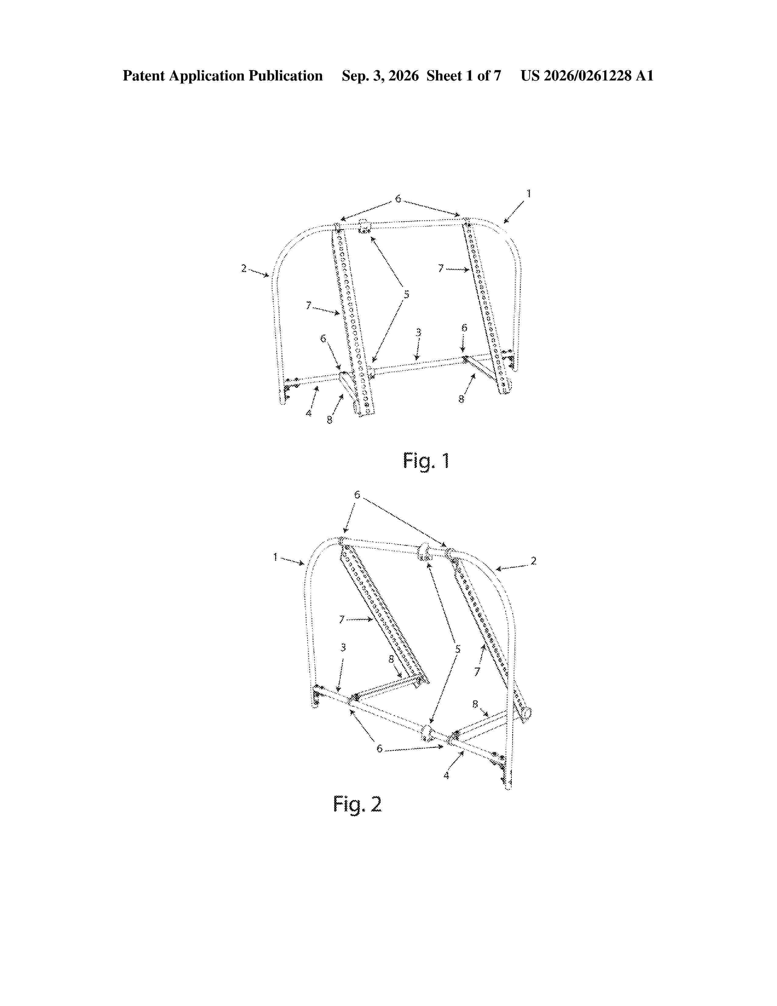
0000 Among other things, the present disclosure provides an adjustable solar panel mounting system comprising a telescoping frame structure configured to fit within side channels of a double-hung window. The telescoping frame structure comprises a first tube having a first diameter and a second tube having a second diameter smaller than the first diameter, wherein the second tube is configured to telescope within the first tube to provide width adjustability. The adjustable solar panel mounting system comprises a locking connector configured to secure the first tube and second tube in a telescoping position. The adjustable solar panel mounting system comprises a mounting bracket attached to the telescoping frame structure and configured to support a solar panel. The adjustable solar panel mounting system comprises a support leg connected to the mounting bracket and configured to position the solar panel at an adjustable angle relative to the window.
Resumen de: US20260261239A1
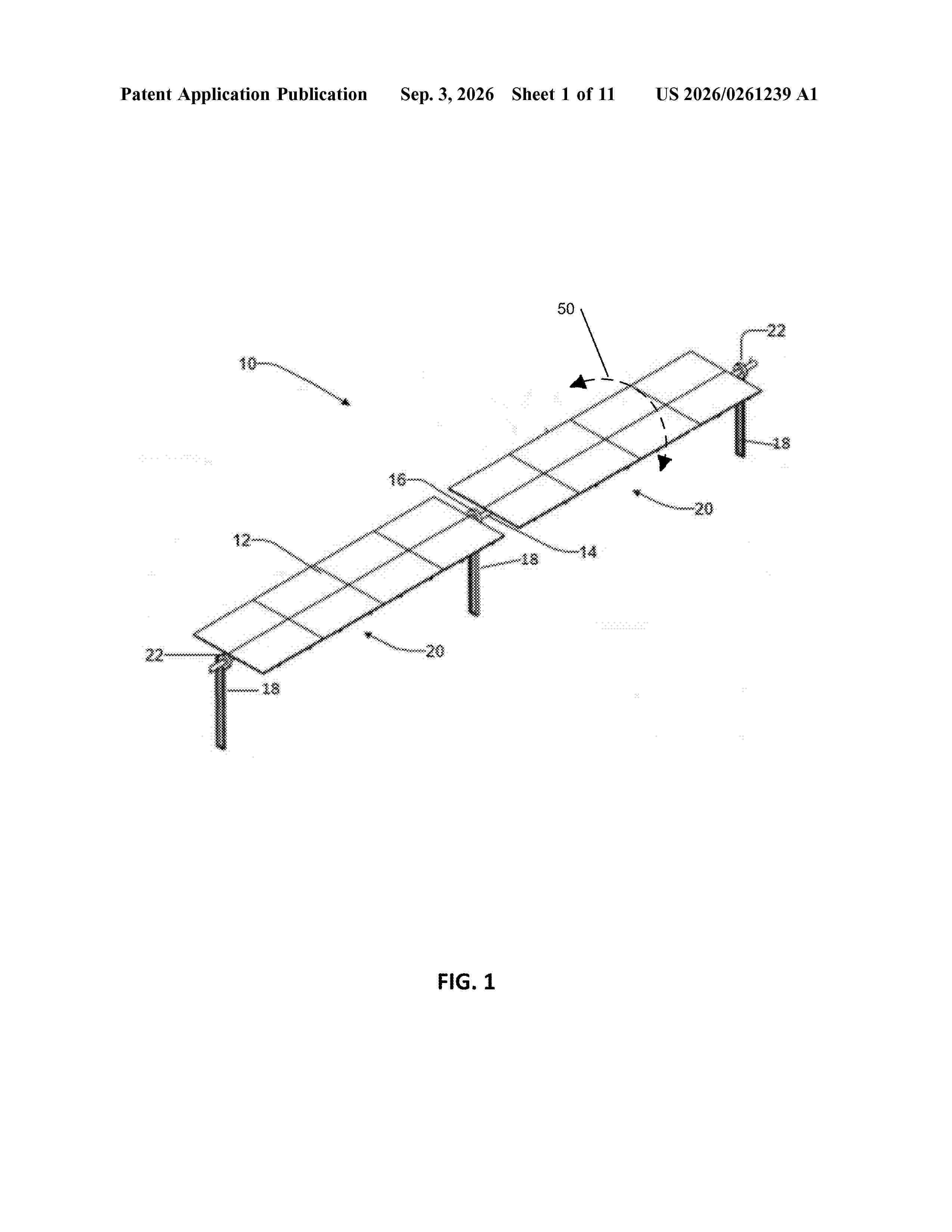
0000 Methods of operating a solar power plant system, including providing initial three-dimensional mapping information for the solar tracker rows, measuring an observed amount of shading of solar tracker rows, using information to determine an expected amount of shading of solar tracker rows, comparing the observed shading to the expected shading, and calculating corrected values of the three-dimensional mapping information for the solar tracker rows. Additional methods include observing shading and light patterns relative to a solar array having a plurality of solar tracker rows to enable corrections to be made to input data regarding positions of solar tracker rows in three-dimensional space, the observations and measurements optionally being facilitated by the use of unmanned aircraft (e.g., drones) during the operation of certain solar tracking algorithms by the solar power plant system.
Resumen de: US20260261237A1
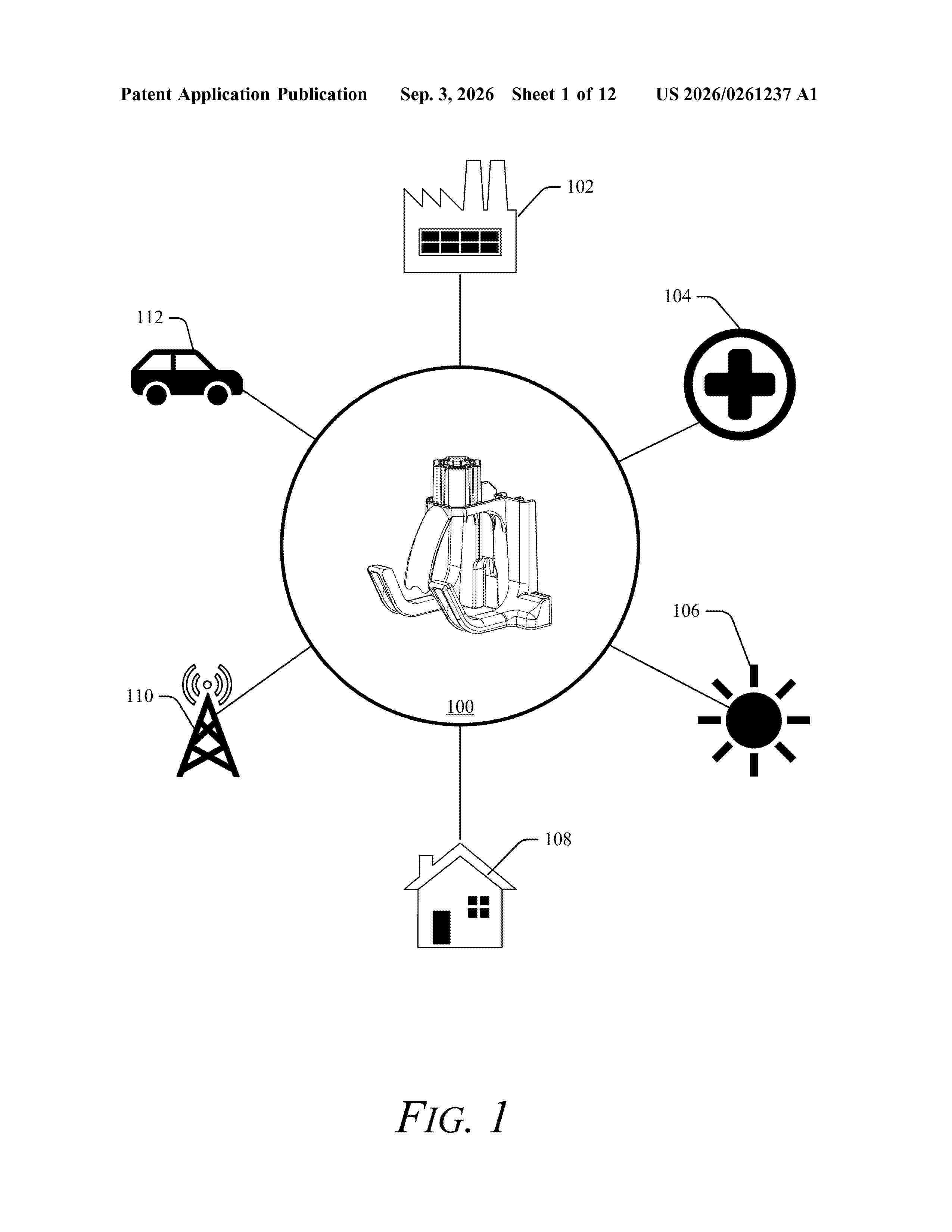
This document describes solar cable cradle fixings (e.g., “cradle fixings”) for routing and securing photovoltaic cables in photovoltaic system installations. An example cradle fixing apparatus includes a mount portion, a cradle portion, and a gate portion. The mount portion is configured to mount on a support structure. The cradle portion extends from the mount portion. The cradle portion defines a channel and a cradle opening. The cradle portion is configured to receive an object (e.g., electrical cable) through the cradle opening and into the channel. The gate portion also extends from the mount portion and is configured to retain the object in the channel between the cradle portion and the gate portion.
Resumen de: US20260261236A1
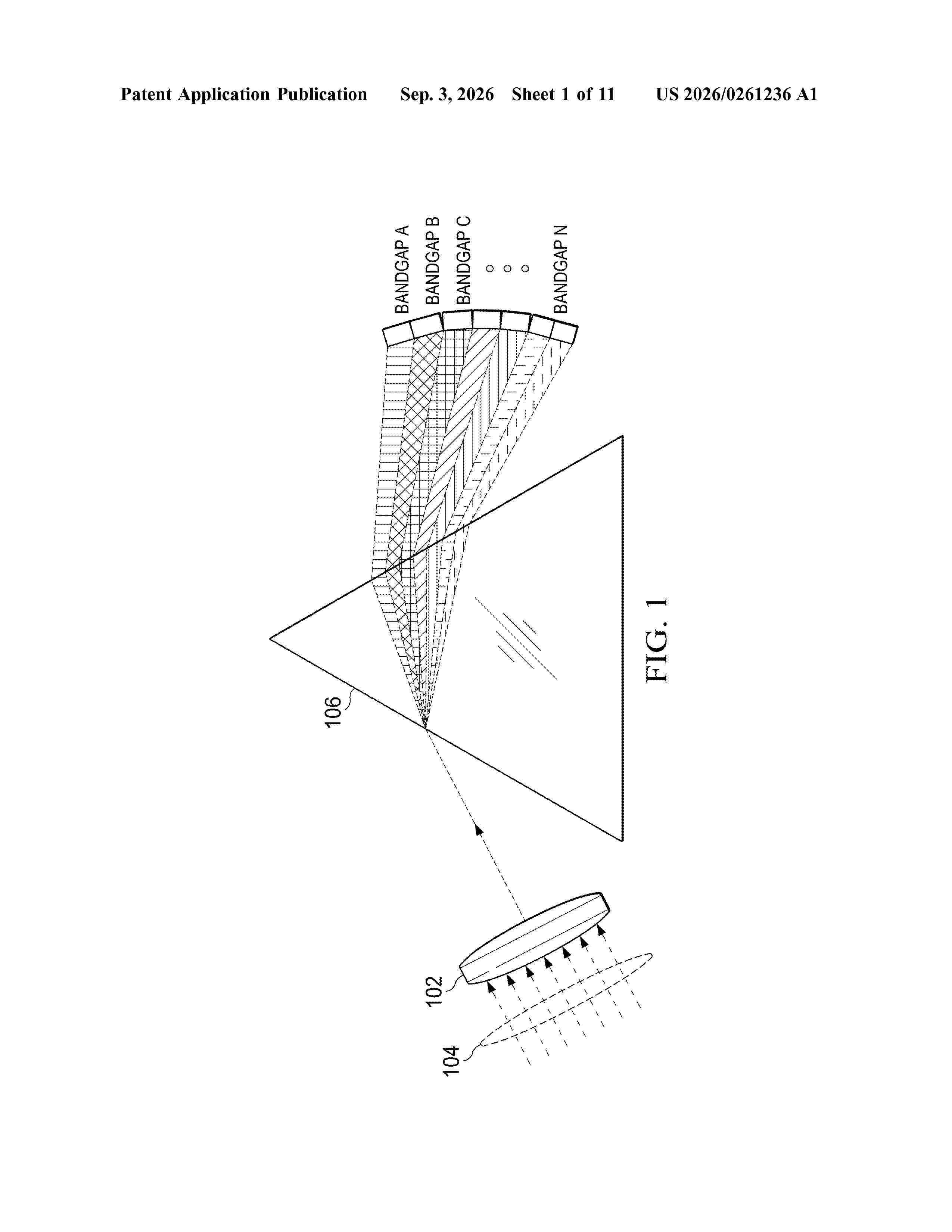
A method to focus sunlight via a lens onto a prism, disperse sunlight via the prism into different wavelength light rays, capture the dispersed light rays with different photo voltaic cells having different energy bandgaps to convert the light rays to electricity. A system with a lens rod array to focus sunlight, a prism rod array wherein respective prism rods disperse sunlight into different wavelength light ray arrays, different photo voltaic cell arrays wherein respective cells are positioned to capture the different wavelength light ray arrays and have different energy bandgap to convert the different light ray arrays to electricity.
Resumen de: US20260261227A1
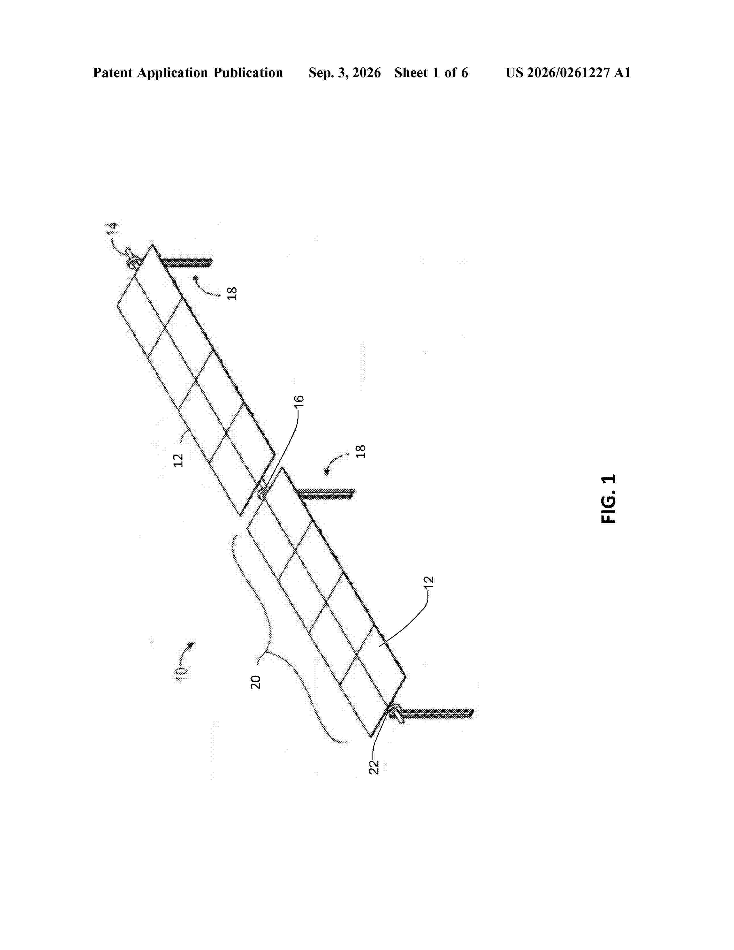
0000 A solar tracker includes a ground pier including a first leg and a second leg, each of the first leg and the second leg configured to be partially embedded in a ground surface, and a solar module supported by the ground pier. At least one of the first leg or the second leg comprises a bimetallic strip.
Resumen de: US20260262330A1
A back-contact solar cell is provided. The back-contact solar cell includes: a solar cell base, a back surface of the solar cell base including a first edge region, a central region, and a second edge region; first finger electrodes and second finger electrodes located in the central region and alternately arranged; an edge busbar located in the first edge region or the second edge region and connected to the first finger electrodes or the second finger electrodes; an edge solder pad located on a portion of at least one finger electrode adjacent to the first edge region or the second edge region; and a connecting member, an orthographic projection of the connecting member on the back surface having a wavy shape.
Resumen de: WO2026183553A1
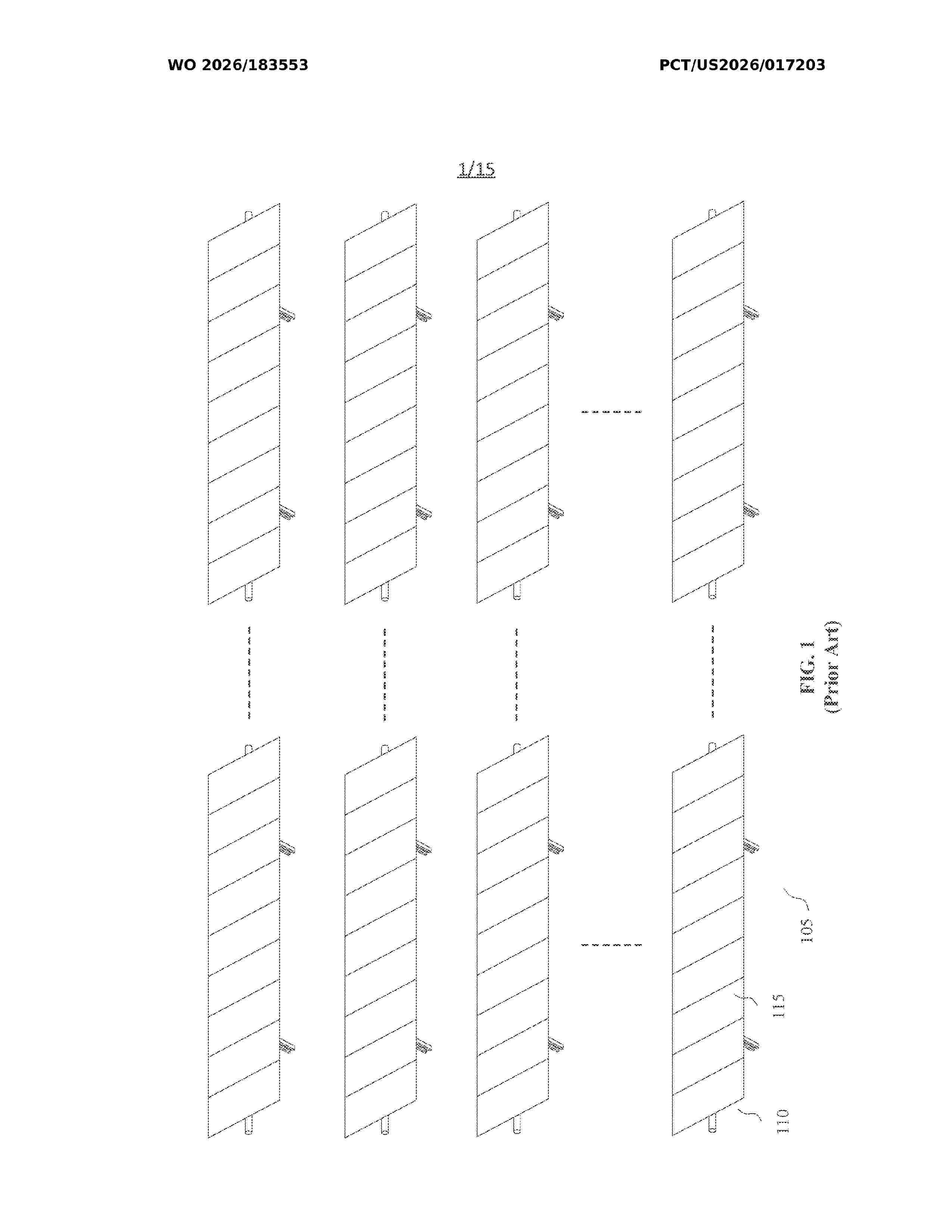
A large solar farm comprises one or more solar arrays, each with hundreds of rows of solar modules. Construction of a solar farm is a process that involves a large amount of human effort and coordination for solar table assembling and installation. The present invention discloses various embodiments for solar table manufacturing and installation monitoring and control. A server is communicatively coupled to various components including a centralized assembly factory, one or more mobile transports for delivering solar tables, portable electronic devices held or worn by on-site personnel. The server receives information from those components for processing and renders one or more interactive interfaces to a terminal device for an authorized user to monitor and control. Implementation of the invention enables improved efficiency, safety, and quality for large solar installation projects.
Resumen de: WO2026182427A1
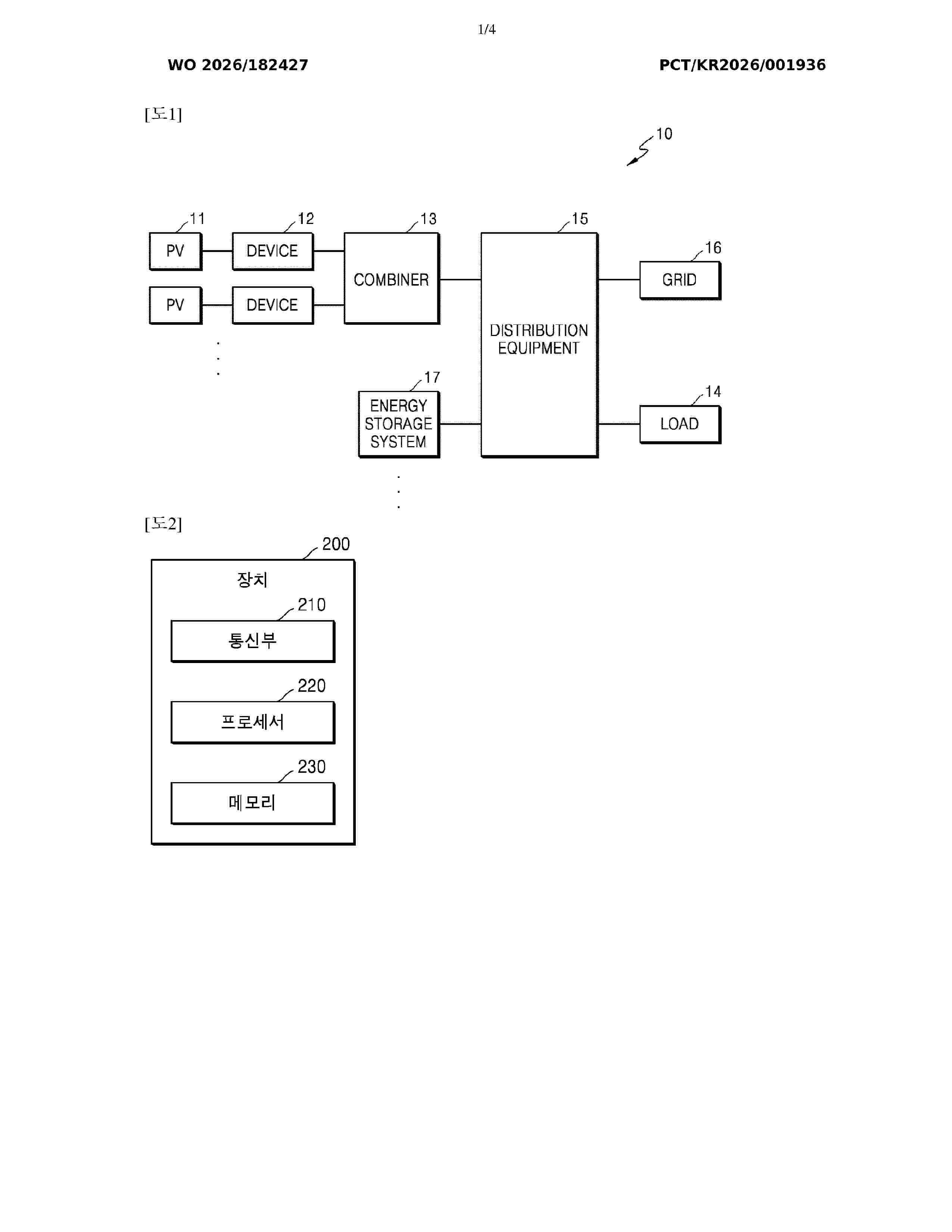
An apparatus according to one aspect comprises at least one memory, and at least one processor, wherein the at least one processor inputs information of a photovoltaic module and information related to the sun into a power generation abnormality cause prediction model as input data of the power generation abnormality cause prediction model, determines whether the power generation of the photovoltaic module is abnormal on the basis of the information of the photovoltaic module and the information related to the sun, derives power generation abnormality cause information of the photovoltaic module on the basis of a result of determining whether the power generation is abnormal, and obtains the power generation abnormality cause information as output data of the power generation abnormality cause prediction model.
Resumen de: WO2026181935A1
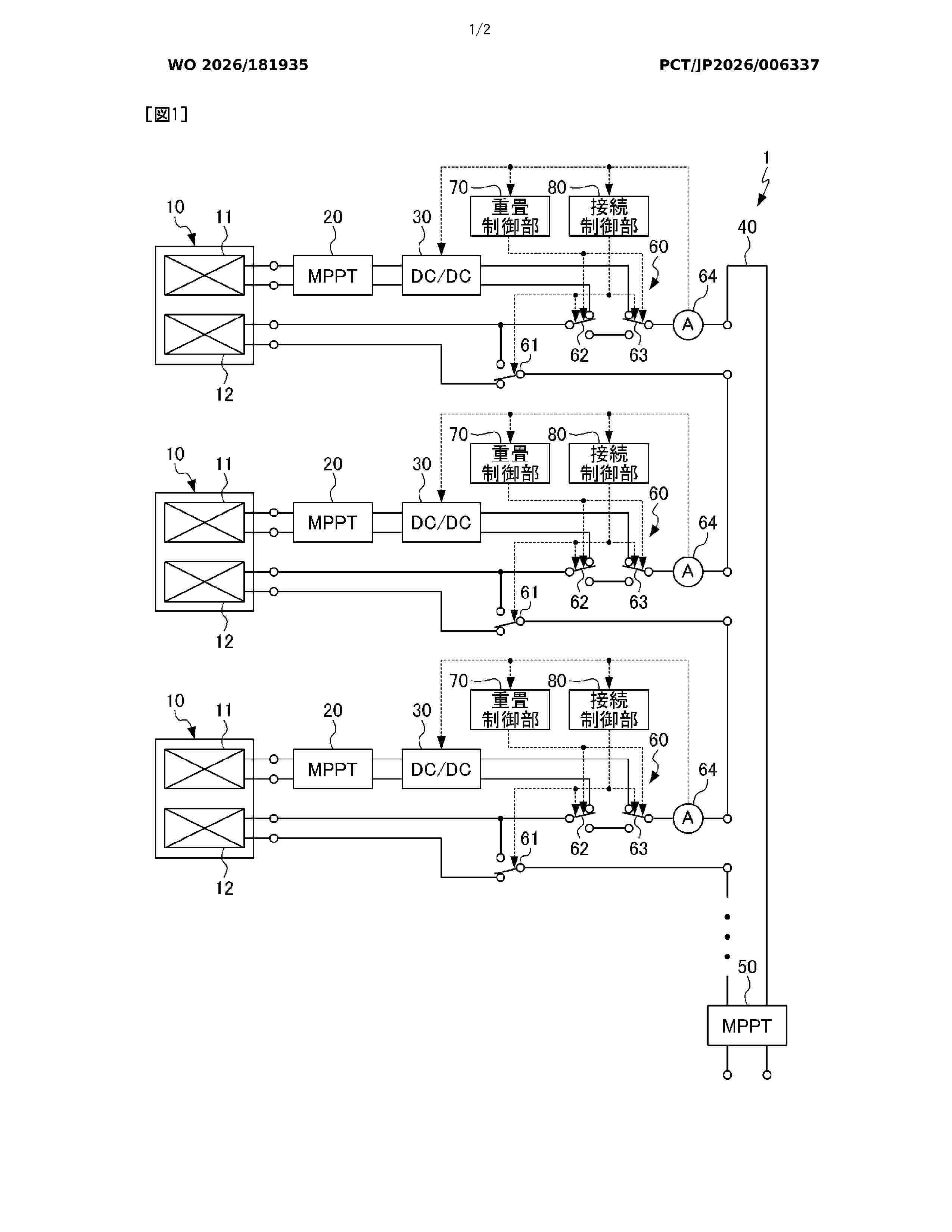
Provided is a solar power generation system comprising: a solar cell module that includes a first solar cell sub-module and a second solar cell sub-module; a sub-module control unit that individually subjects the first solar cell sub-module to maximum power point tracking control; a DC-DC converter that matches the output voltage or the output current of the first solar cell sub-module to the output voltage or the output current of the second solar cell sub-module; a main circuit that connects the second solar cell sub-module in series or in parallel; a main output control device that subjects the output of the main circuit to maximum power point tracking control; and a connection circuit that is configured such that the second solar cell sub-module can be inserted into the main circuit, and the output of the first solar cell sub-module as adjusted by the DC-DC converter can be superimposed on the output of the second solar cell sub-module.
Resumen de: WO2026182624A1
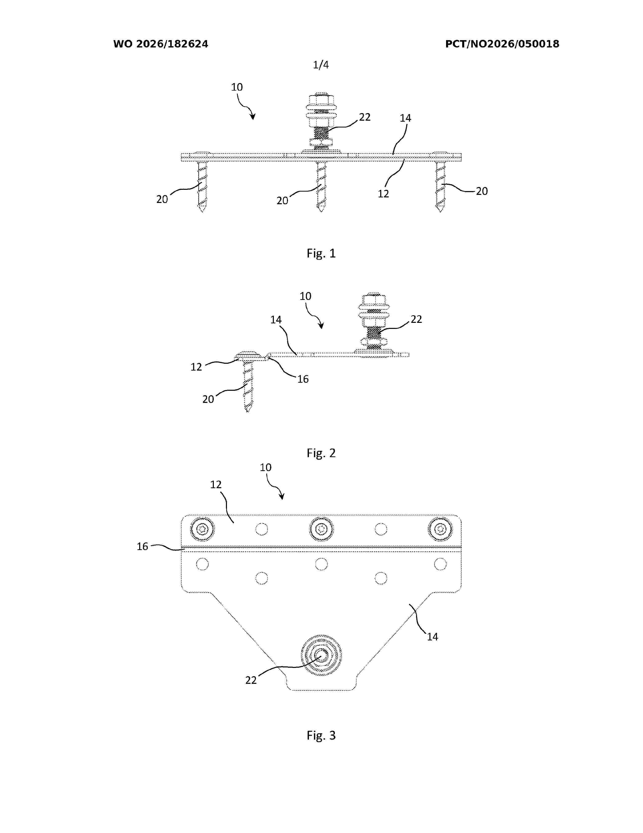
Mounting plate (10) for roof shingles, comprising a plate-shaped body with a first plate part (12) and a second plate part (14), wherein the first plate part (12) is arranged for attachment to a substrate on a roof, such as a roof board, roof decking, or similar, and the second plate part (14) is arranged to be positioned overlying a shingle plate (40) and comprises an upwardly projecting fastening bolt (22) for attachment of roof equipment. The plate-shaped body comprises a longitudinal fold (16) that forms a bend between the first plate part (12) and the second plate part (14), whereby the first plate part (12) is recessed relative to the second plate part (14).
Resumen de: WO2026179067A1
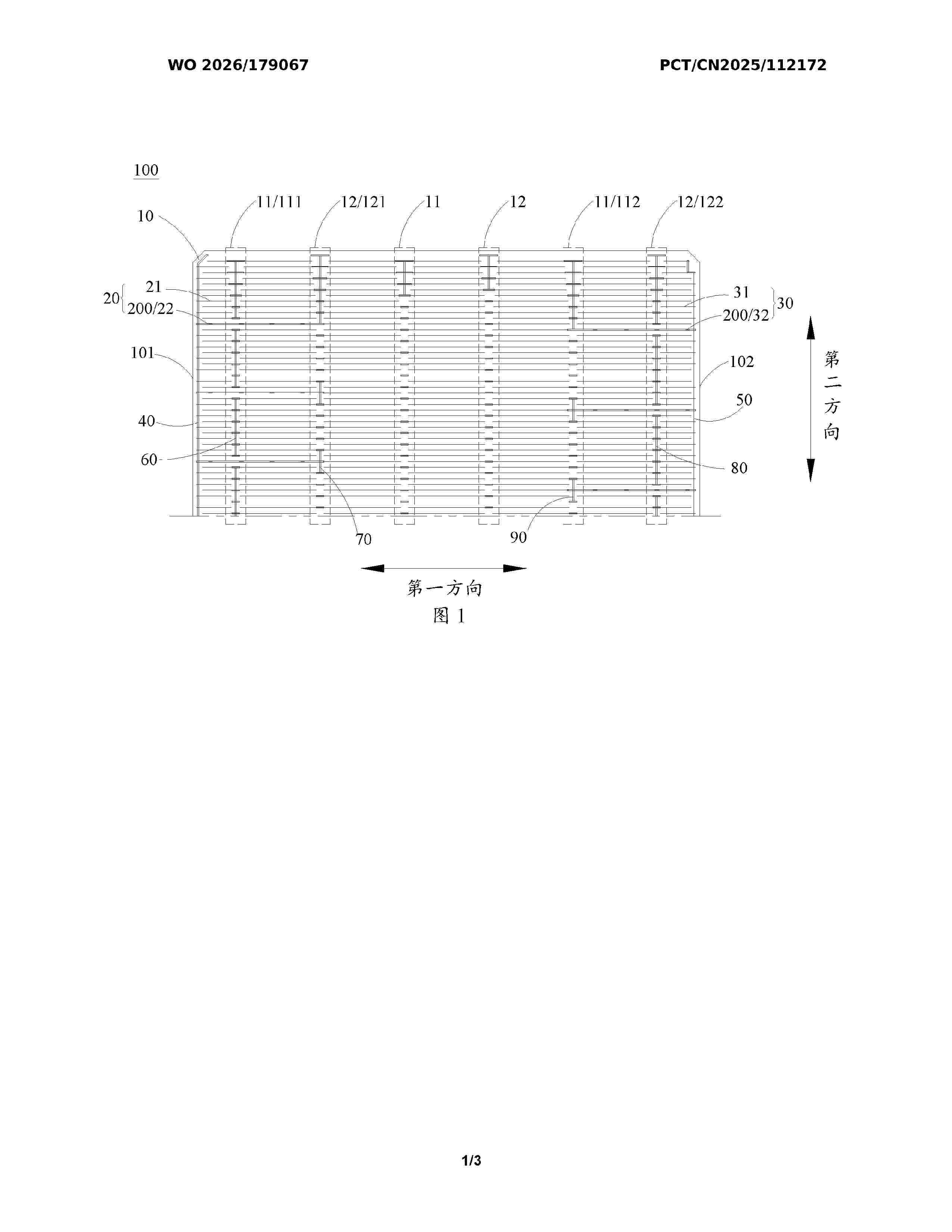
The present disclosure is applicable to the technical field of photovoltaics, and provides a cell, a module, and a photovoltaic system. The cell is provided with a busbar on a silicon substrate. The busbar comprises a connecting conductor and fine grid lines. The fine grid lines are arranged on a surface of the connecting conductor facing the silicon substrate. The connecting conductor is not in physical contact with a doped layer, and the fine grid lines are in physical contact with the doped layer. The fine grid lines collect carriers generated by the silicon substrate.
Resumen de: WO2026181082A1
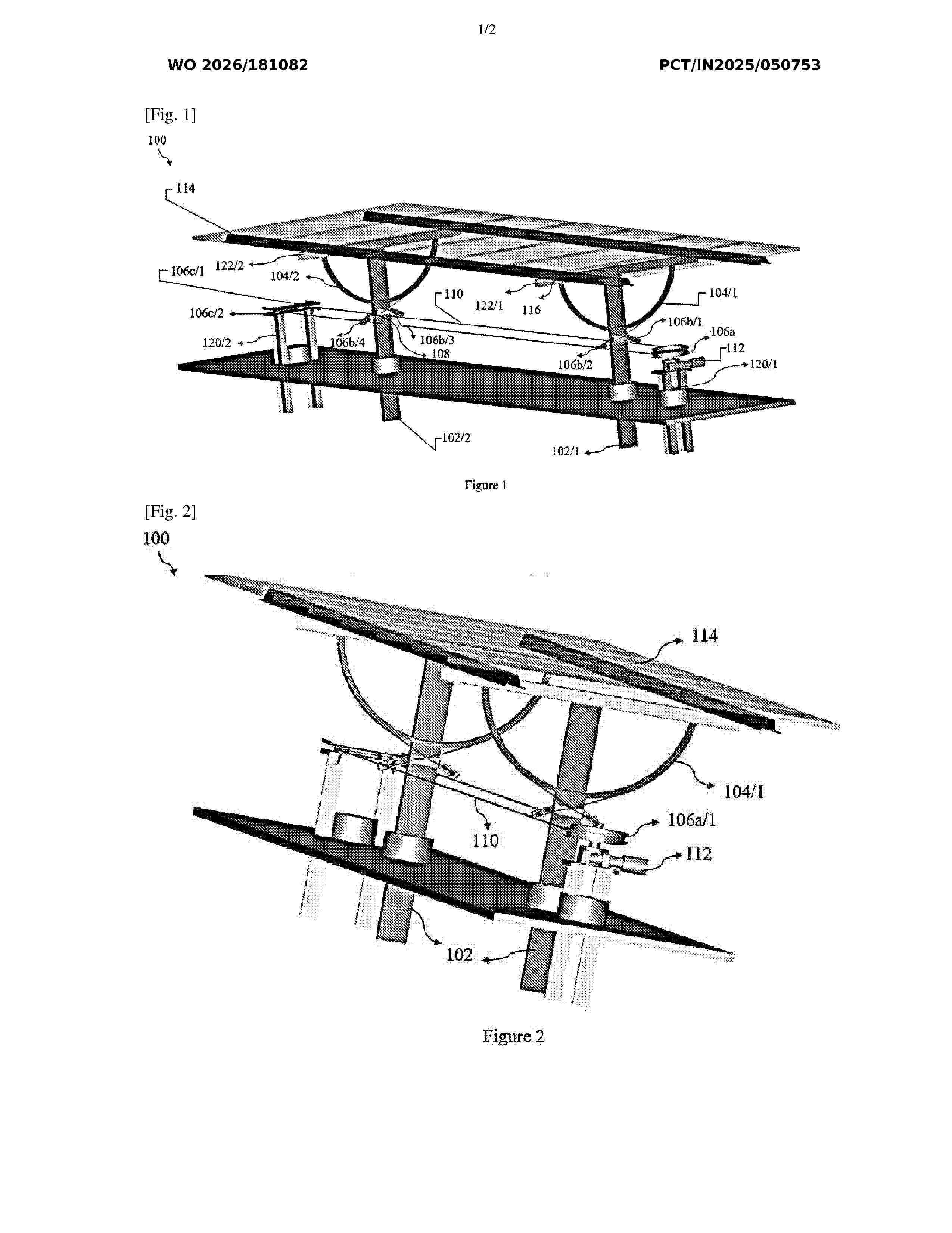
The present invention discloses a tubeless sun tracker system (100) for solar panels (114), comprising: one or more column posts (102) for supporting the solar panels (114), one or more rafters (122) connected to the solar panels (114) for structural support and movement control, at least one crescent guide (104) for adjusting the solar panels (114), one or more steel cords (110) threaded through one or more pulleys (106) and connected to the crescent guide (104) for facilitating synchronized movement of the solar panels (114), at least one DC motor (112) connected to the steel cords (110) to facilitate movement of the solar panels (114) by actuating movement of the pulleys (106), and at least one control unit (118) connected to the DC motor (112) for controlling movement and orientation of the solar panels (114) for enabling automated sun tracking.
Resumen de: WO2026182142A1
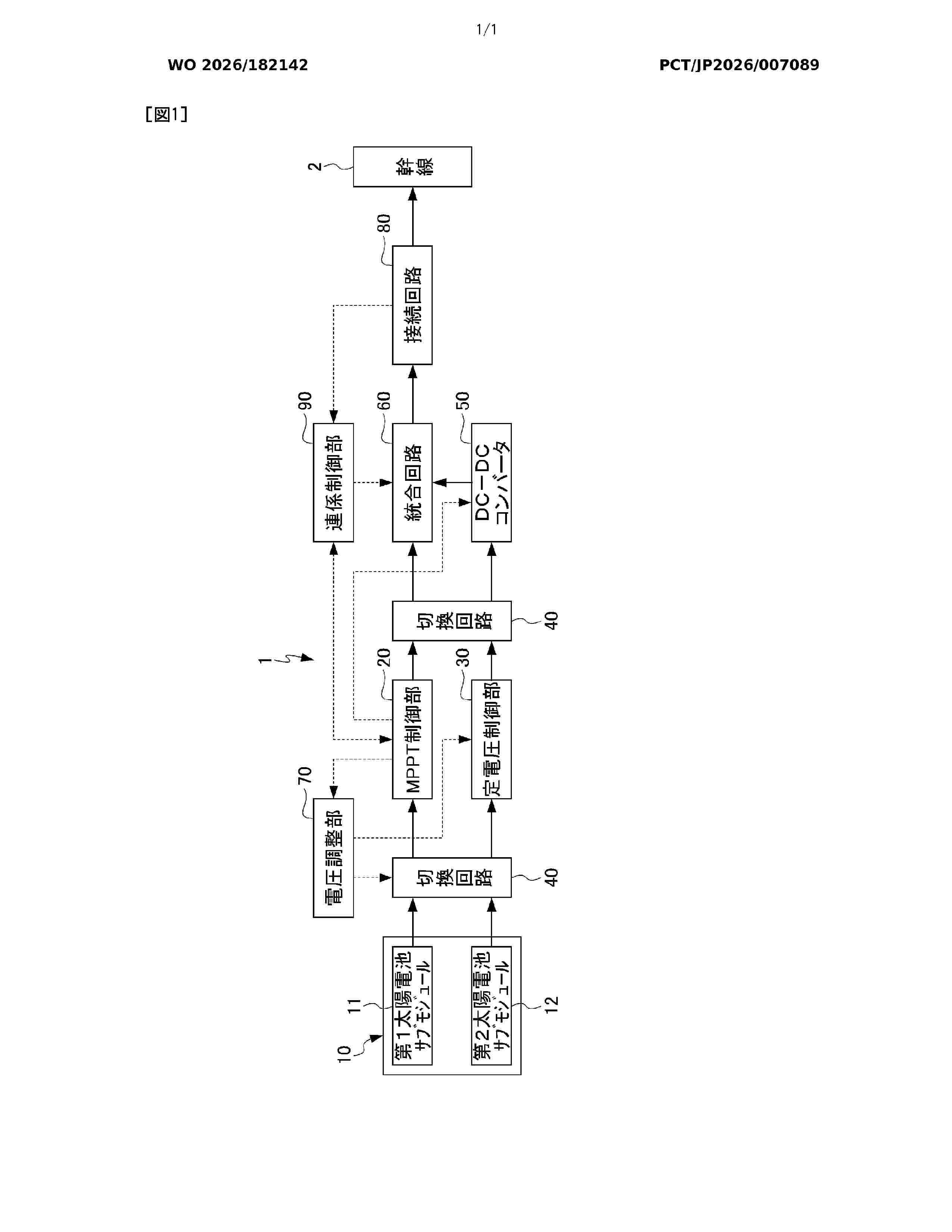
This photovoltaic power generation unit comprises: a solar cell module including a first solar cell sub-module and a second solar cell sub-module that independently output power; an MPPT control unit that outputs power from the first solar cell sub-module and performs maximum power point follow-up control of the output; a constant voltage control unit that outputs power from the second solar cell sub-module and performs constant voltage control of the output; a DC-DC converter that matches the voltage or current of the output of the constant voltage control unit with the voltage or current of the output of the MPPT control unit; and an integration circuit that superimposes the output of the constant voltage control unit on the output of the MPPT control unit.
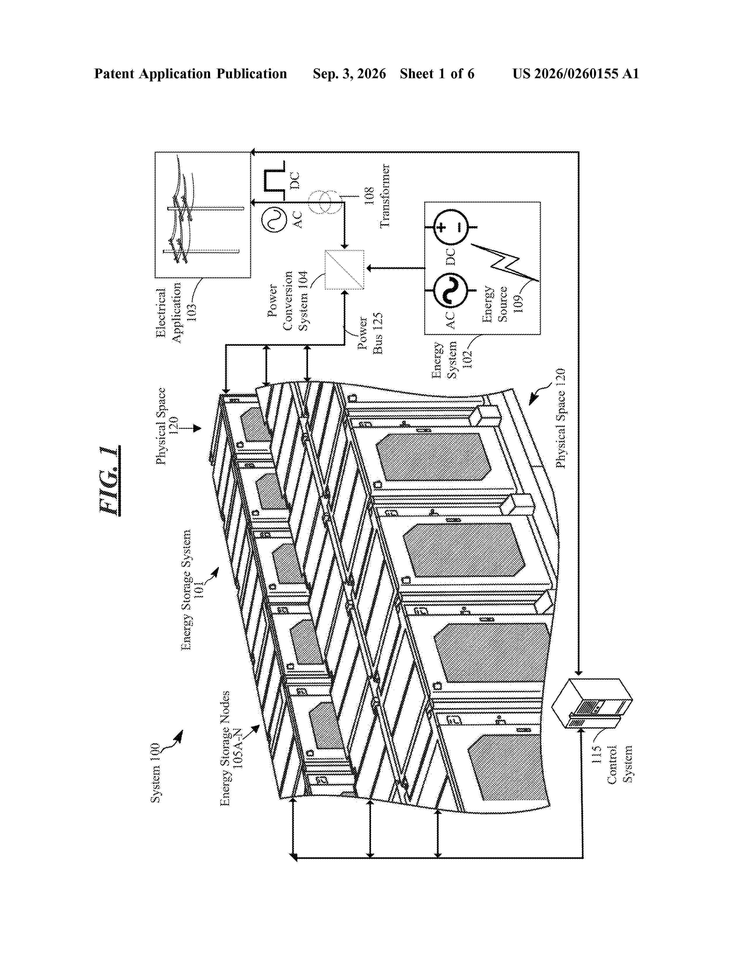
Resumen de: US20260260155A1
A computing device includes a memory, a processor coupled to the memory, and programming in the memory. Execution of the programming by the processor configures the computing device to: accept as inputs a plurality of known configurations of at least one type of physically modular device that includes associated physical artifacts, train a machine learning model to learn types of configurations corresponding to the at least one type of physically modular device based on the inputted plurality of known configurations of the at least one type of physically modular device and the associated physical artifacts, and create at least one valid configuration of a physically modular device when fed a set of physical artifacts of the physically modular device based on the learned types of configurations of the machine learning model.
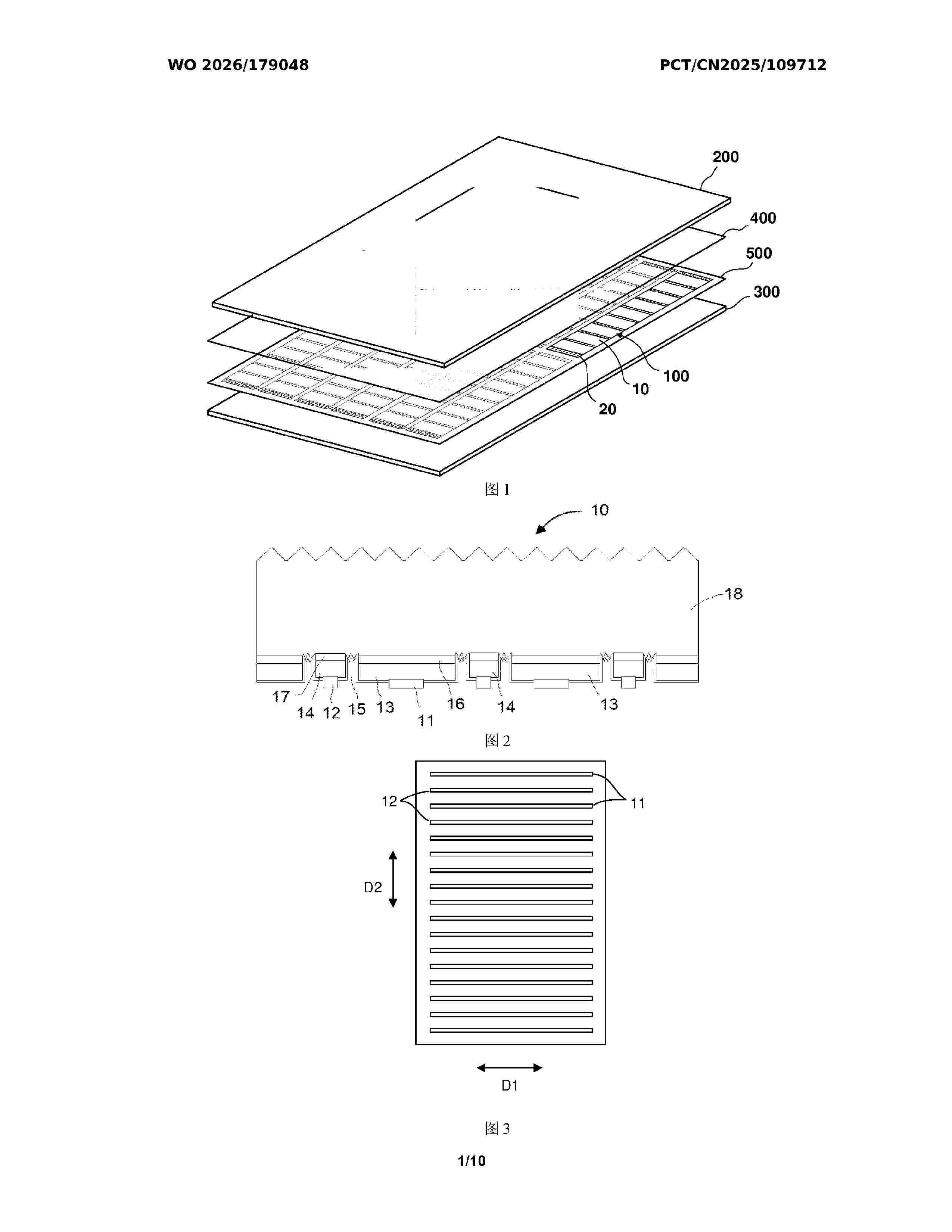
Resumen de: WO2026179048A1
A solar cell string (100), a solar cell module, a power generation device, and an electric device. The solar cell string (100) comprises: a plurality of solar cells (10), wherein each solar cell (10) comprises a cell body and an electrode layer located on one side of the cell body, the electrode layer comprising a first electrode (11) and a second electrode (12) spaced apart and having opposite polarities; an conductive interconnection film (20), wherein the plurality of solar cells (10) are located on one side of the conductive interconnection film (20) and are electrically connected to the conductive interconnection film (20), the conductive interconnection film (20) comprises a base film (21) and a conductive layer (22) located on the side of the base film (21) facing the solar cells (10), the conductive layer (22) comprising a first conductive structure (221) and a second conductive structure (222); and an adhesive body (30), wherein the adhesive body (30) is insulating, the adhesive body (30) is disposed in the area of the base film (21) where the conductive layer (22) is not provided, and the adhesive body (30) is in contact with the base film (21) and the cell bodies.
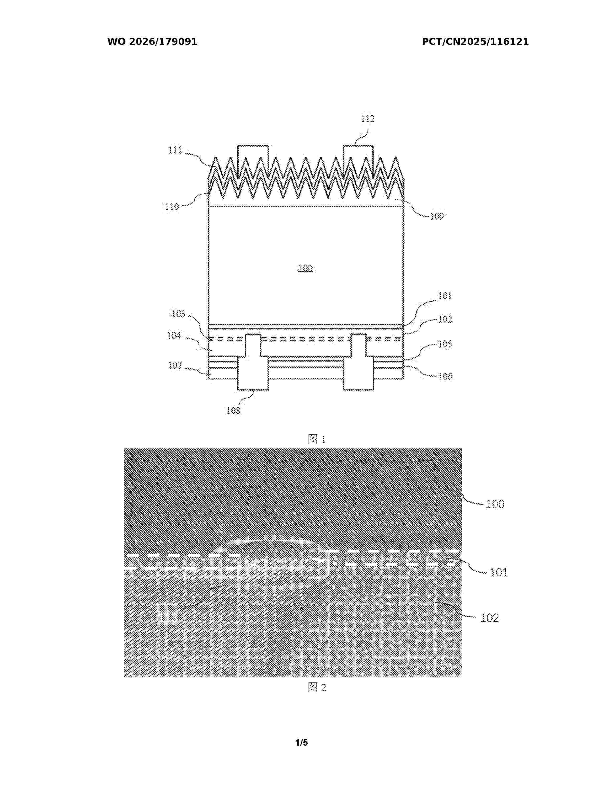
Resumen de: WO2026179091A1
The present application provides a solar cell, comprising: a silicon substrate; a first tunneling layer, the first tunneling layer having a plurality of first openings; a first crystalline conductive layer, the first crystalline conductive layer extending into at least one first opening and contacting the silicon substrate; a second tunneling layer, the second tunneling layer having a plurality of second openings; and a second crystalline conductive layer, the first crystalline conductive layer and/or the second crystalline conductive layer extending into at least one second opening, such that the second crystalline conductive layer contacts the first crystalline conductive layer. The degree of concentration of the second openings in the second tunneling layer is greater than the degree of concentration of the first openings in the first tunneling layer. The design of the solar cell not only effectively reduces carrier recombination in the solar cell, improving the passivation effect of the cell, but also increases carrier transmission channels, improving the carrier transmission efficiency of the cell, thereby improving the efficiency of the solar cell.
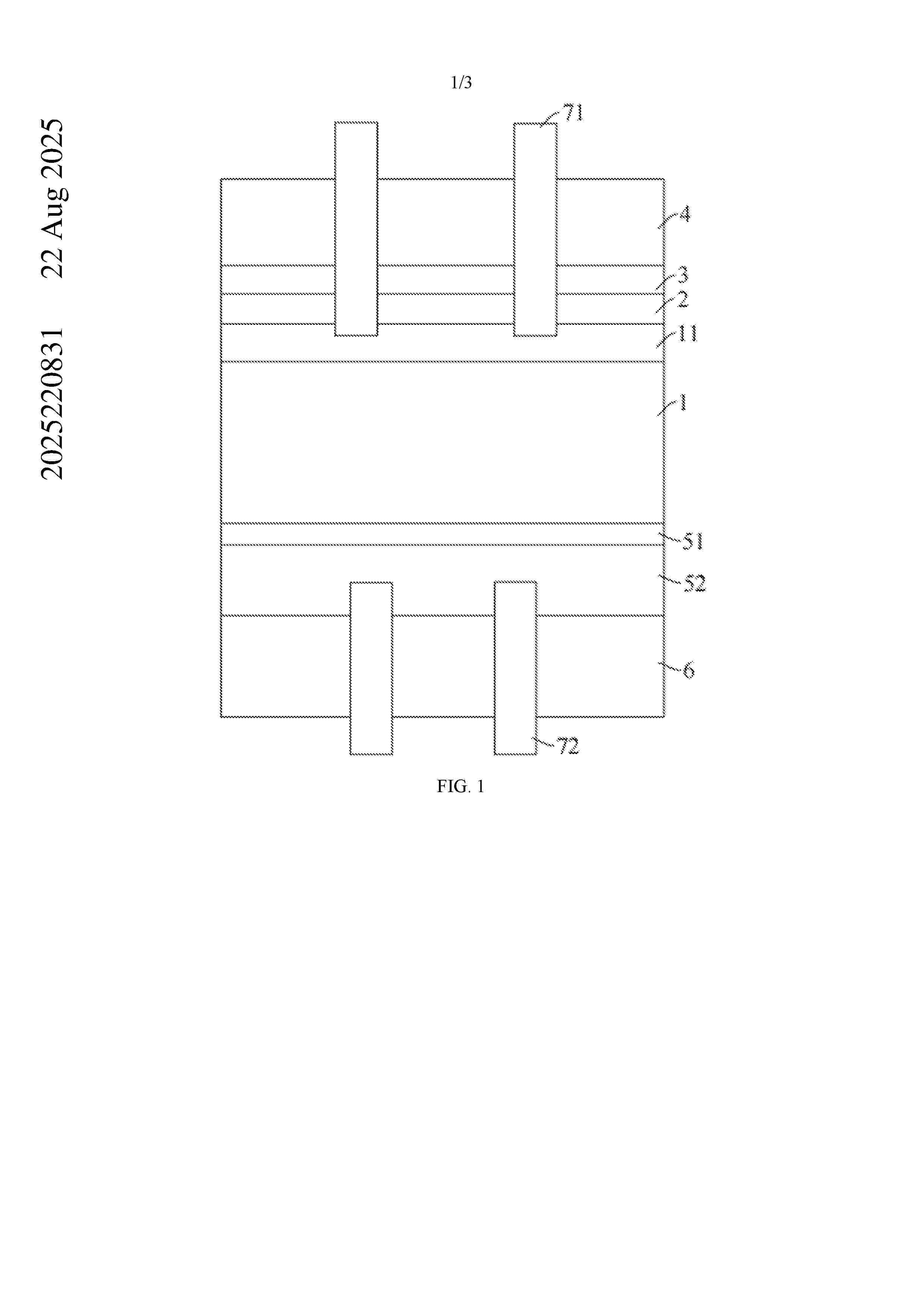
Resumen de: AU2025220831A1
The present application relates to a solar cell, a preparation method thereof, and a photovoltaic module. The solar cell includes a silicon substrate, and an emitter, a first silicon oxide layer, and an aluminum oxide layer are sequentially stacked on a light-receiving surface of the silicon substrate. The thickness of the first silicon oxide layer is in a range from 0.2 nm to 1.2 nm. 5 The present application relates to a solar cell, a preparation method thereof, and a photovoltaic module. The solar cell includes a silicon substrate, and an emitter, a first silicon oxide layer, and an aluminum oxide layer are sequentially stacked on a light-receiving surface of the silicon 5 substrate. The thickness of the first silicon oxide layer is in a range from 0.2 nm to 1.2 nm. ug u g 11 (111) 51 (511) 6(61) ug u g
Nº publicación: WO2026183204A1 03/09/2026
Solicitante:
THE AES CORP [US]
THE AES CORPORATION
Resumen de: WO2026183204A1
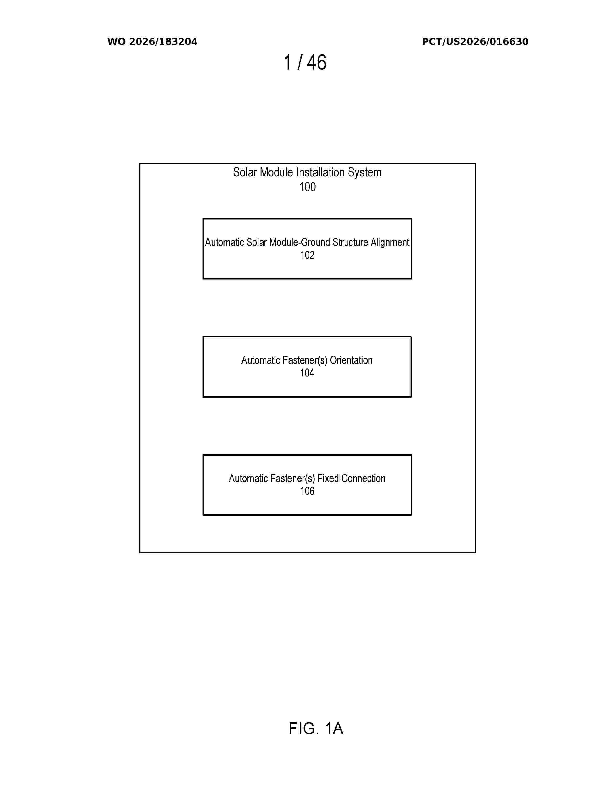
A system and method for automatic aligning and connection of solar modules and ground structures. Installation of a solar module to a ground structure can be both labor-intensive and time-intensive. The system and method performs one or more automatic operations that may be used to install the solar module to the ground structure, including automatically orienting fasteners into a predetermined orientation; automatically moving one or both of the solar module or a part of the ground structure so that the solar module and the part of the ground structure are physically contacting/aligned; and automatically fixedly connecting the solar module and the part of the ground structure together using the fasteners with predetermined orientation.
 BOPI
BOPI
 Sede Electrónica