Si deseas distinguir tus productos, servicios o ambos de los de otra empresa, es posible que necesites una marca o nombre comercial. Descubre qué son, en qué consiste su procedimiento de registro y qué implica.

Información sobre los plazos de presentación de solicitudes de transformación de marcas de la Unión Europea en marca nacional española. Más información


Si tienes un nuevo dispositivo, producto o procedimiento que resuelva un problema técnico o tenga una ventaja práctica, existen distintas formas de protegerlo en España y en otros países. Descubre cómo hacerlo.

¿Tu innovación reside en la estética, la ornamentación o la apariencia de tu producto? Protégela mediante un diseño industrial. Descubre qué derechos confiere el registro y cómo realizar la tramitación.

Las indicaciones geográficas protegen el nombre de un producto originario de una zona geográfica, a la cual le debe una determinada calidad, reputación u otra característica. Descubre qué son, en qué consiste su procedimiento de registro y qué beneficios conceden.

Las patentes publicadas en todo el mundo son una valiosa fuente de información científica, técnica y comercial.

Si eres emprendedor/a o una empresa y quieres potenciar y mejorar la rentabilidad de tu negocio protegiendo de forma adecuada los activos intangibles de tu organización, en este espacio encontrarás lo necesario.


 789
resultados
789
resultados
 Última actualización
15/09/2026 [08:08:00]
Última actualización
15/09/2026 [08:08:00]


 Resultados 50 a 75 de 789

Resumen de: US20260257913A1
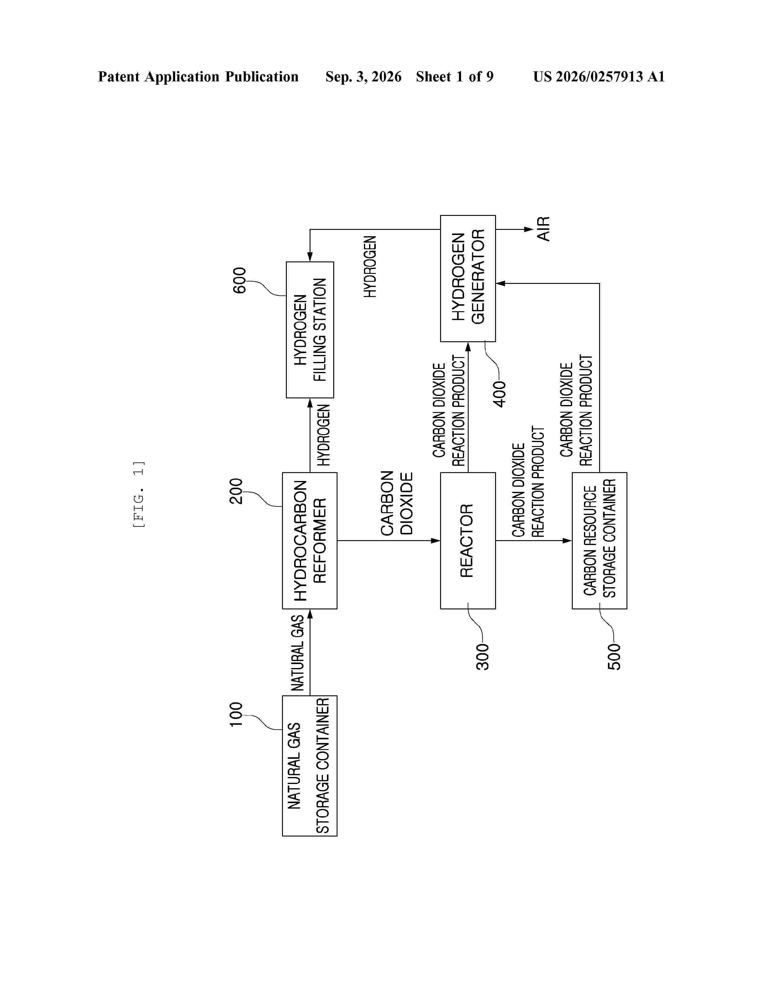
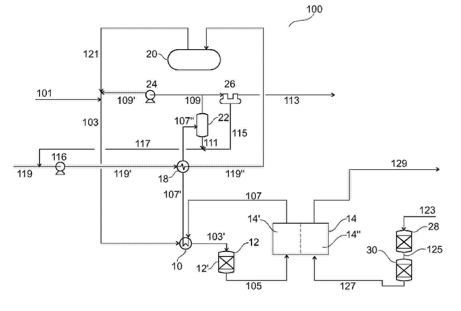
Proposed is a system for generation of blue hydrogen through natural gas reforming, carbon dioxide capture, carbon resource utilization, and reaction product storage. The system includes a natural gas storage container for storing liquefied natural gas including shale gas, a hydrocarbon reformer in which a gas mixture containing hydrogen and carbon dioxide is produced, a hydrogen filling station in which hydrogen is received and stored, a reactor in which carbon dioxide produced is received and reacted with a basic alkali mixed solution to capture carbon dioxide and in which a reaction product is collected and a carbon dioxide reaction product and a waste solution are separated from the reaction product, a carbon resource storage container storing the carbon dioxide product, and a hydrogen generator in which the carbon dioxide reaction product is used to product hydrogen, and the produced hydrogen is delivered to the hydrogen filling station.

Resumen de: US20260258513A1
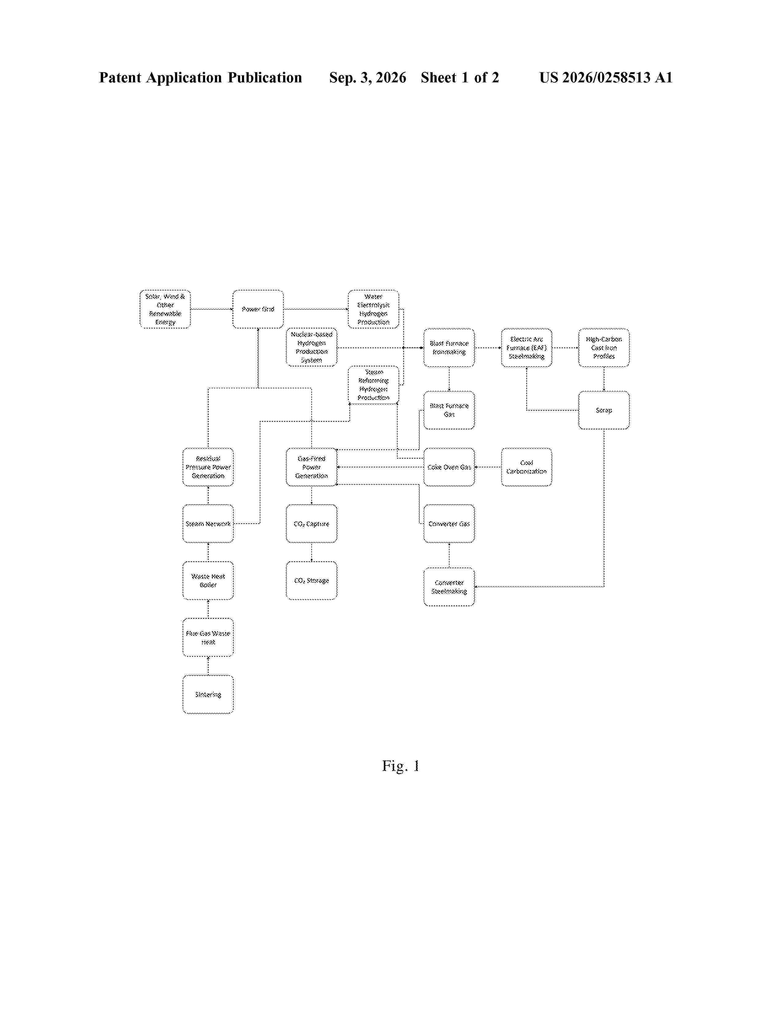
0000 The present invention discloses a systematic carbon emissions reduction method for whole process of steel production and casting, comprising the steps of: injecting hydrogen into a blast furnace, wherein the hydrogen is sourced from a nuclear-based hydrogen production system, a water electrolysis hydrogen production system, and a coke oven gas-steam reforming hydrogen production system; wherein electrical energy consumed by the water electrolysis hydrogen production system is sourced from gas-fired power generation, steam residual pressure power generation, solar power generation, wind power generation, and nuclear power generation; wherein combustible gases used for the gas-fired power generation are coke oven gas, blast furnace gas, and converter gas; wherein steam for the steam residual pressure power generation is sourced from a sintering waste heat boiler; wherein steam for the coke oven gas-steam reforming hydrogen production is low-pressure steam exhausted from the residual pressure power generation; producing end products comprising cast steel sections and casting materials including high-carbon ductile cast iron profiles with a carbon content of 2-4% and a silicon content of 2-4%, and high-carbon ductile cast steel profiles with a carbon content of 1-2% and a silicon content of 1-1.9%; and recycling scrap from the end products into a converter or an electric arc furnace for smelting.
Resumen de: US20260257925A1
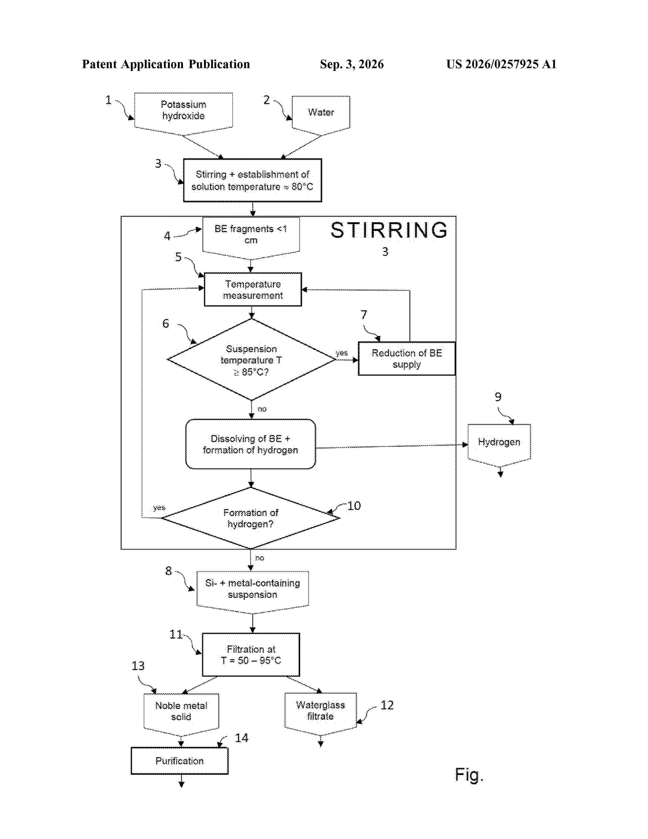
The present invention relates to a method of physical and energetic utilization of silicon components that are obtained in electrical scrap recycling. In order to create a recycling method which is effective in terms of time, plant technology and energy, it is proposed that a silicon component be dissolved in an alkali under the process pressure (p) and a first suspension temperature in the range from 50° C. to equal to or greater than the boiling point of the alkali at the process pressure p. After the silicon has been dissolved, the resultant suspension is filtered for separation of meta-, di- and oligosilicate, and the second suspension temperature is maintained during the filtration within the temperature range specified from 50 to less than the boiling point of the alkali.
Resumen de: WO2026181397A1
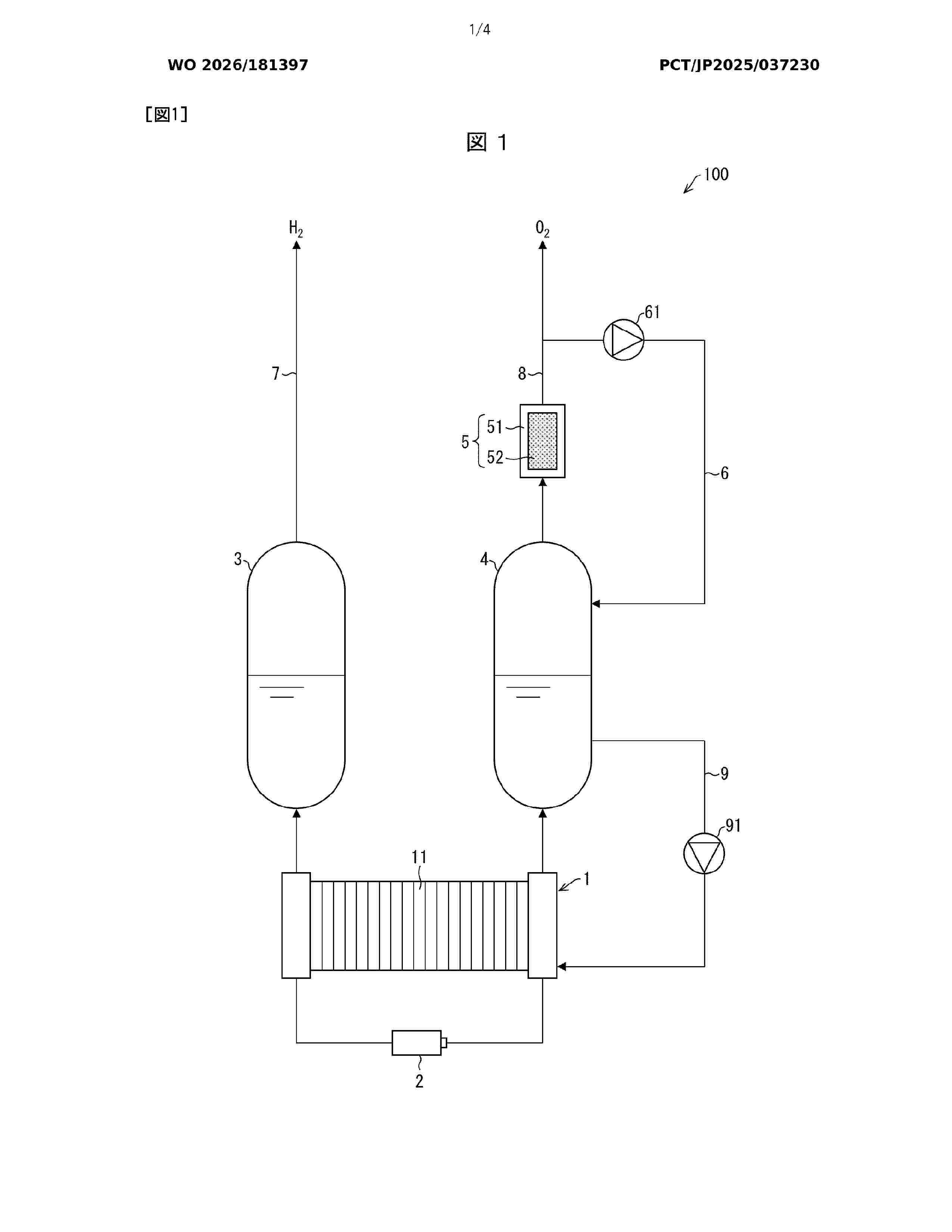
A water electrolysis apparatus (100) comprises: a catalyst (52) that is disposed outside an oxygen gas-liquid separator (4) and reduces hydrogen mixed into oxygen; and an oxygen circulation line (6) in which a blower (61) is disposed and which returns oxygen that has passed through the catalyst (52) to the oxygen gas-liquid separator (4).
Resumen de: US20260258558A1
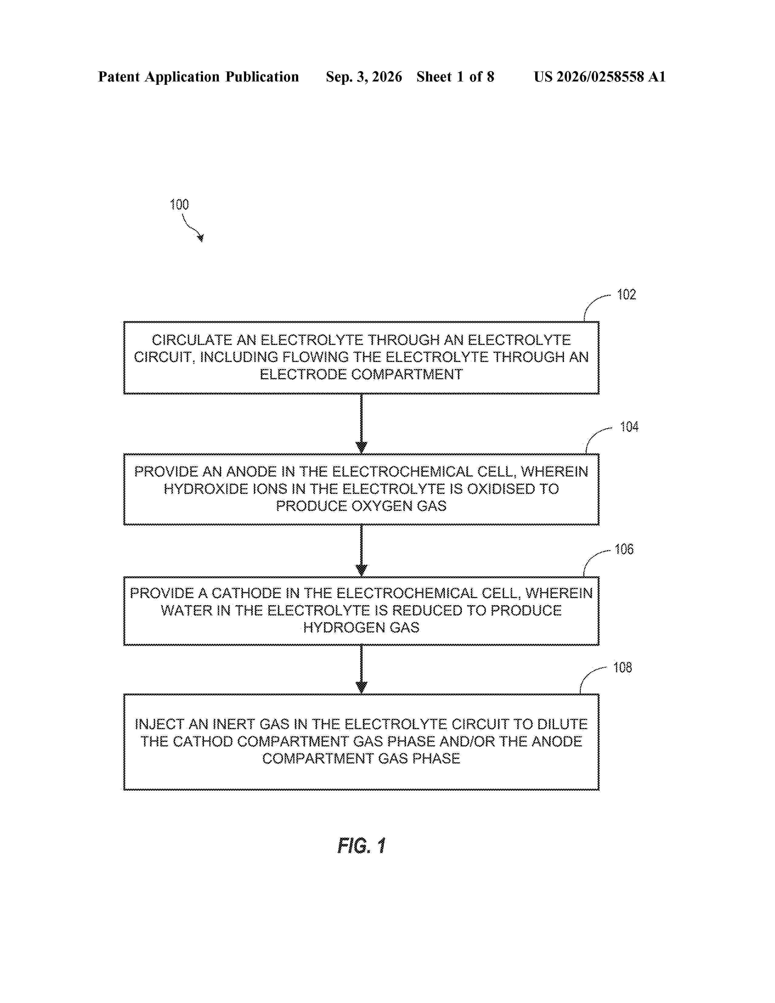
0000 A method to generate hydrogen gas comprises circulating an electrolyte through an electrolyte circuit including an electrochemical cell comprising an anode and a cathode, wherein hydroxide ions in the electrolyte are oxidized at the anode to produce oxygen gas and water in the electrolyte is reduced at the cathode to produce hydrogen gas. The method further includes introducing an inert gas into the electrolyte circuit to dilute a gas phase of the electrolyte circuit.
Resumen de: WO2026182019A1
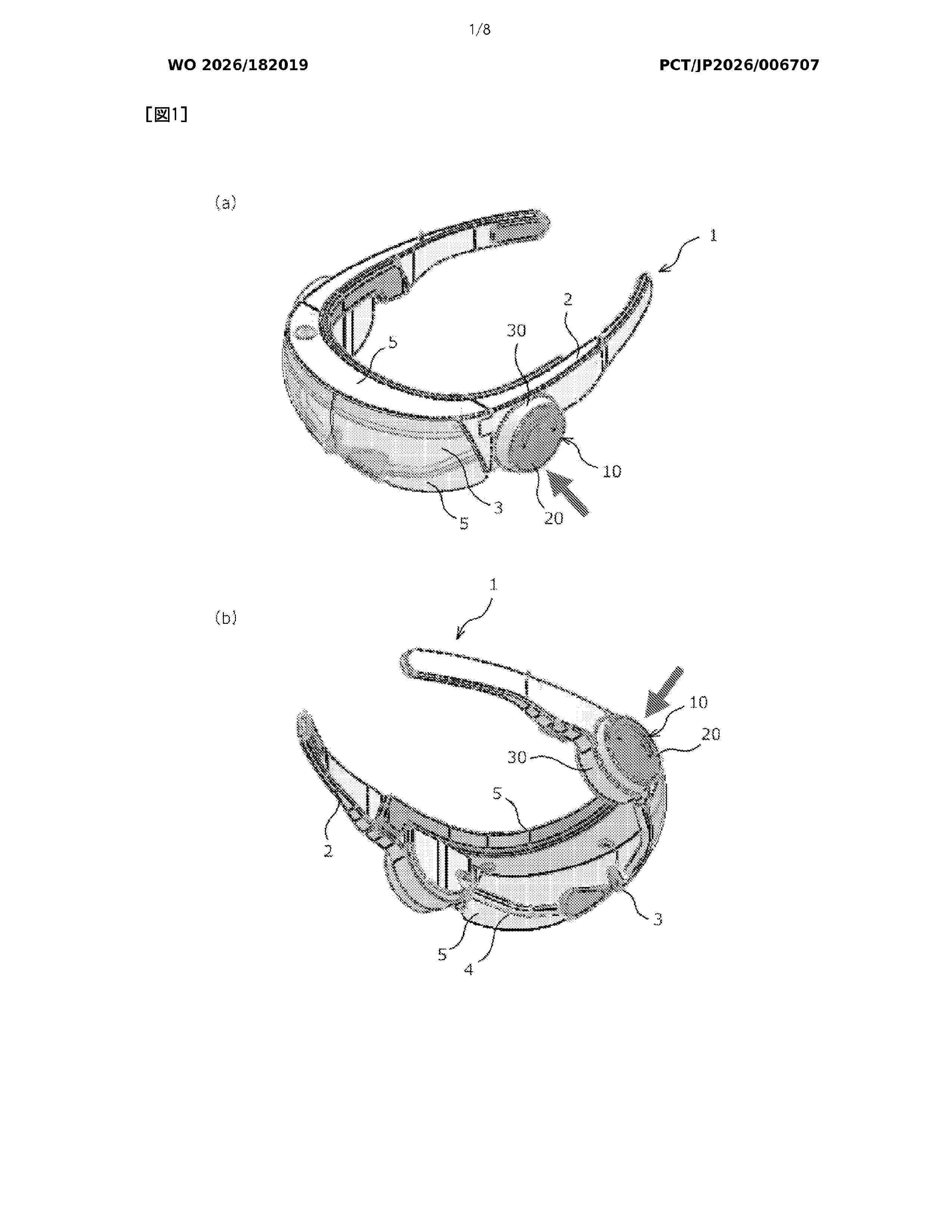
The present invention provides an electrolytic hydrogen supply device to be attached to at least one side of goggles. A hydrogen supply device according to the present invention comprises: an electrolytic cell in which a pair of positive and negative electrodes are disposed in the vertical direction and which is capable of storing electrolytic water; and an electrolytic cell receiving section which has a recess that opens from the bottom toward the outside of the side of the goggles, and which is configured to insert and fix the electrolytic cell in the recess from the outside toward the inside to the bottom. The electrolytic cell has a pair of front and rear sealing members in the inward and outward directions for sealing the inner wall of the electrolytic cell receiving section and the outer wall of the electrolytic cell, and has, above the electrolytic cell, a reserve tank space formed in a gap between the outer wall of the electrolytic cell and the inner wall of the electrolytic cell receiving section between the front and rear sealing members, and a first gas film that allows a gas containing hydrogen and water vapor in the electrolytic cell to pass through and be released into the reserve tank space.
Resumen de: WO2026180519A1
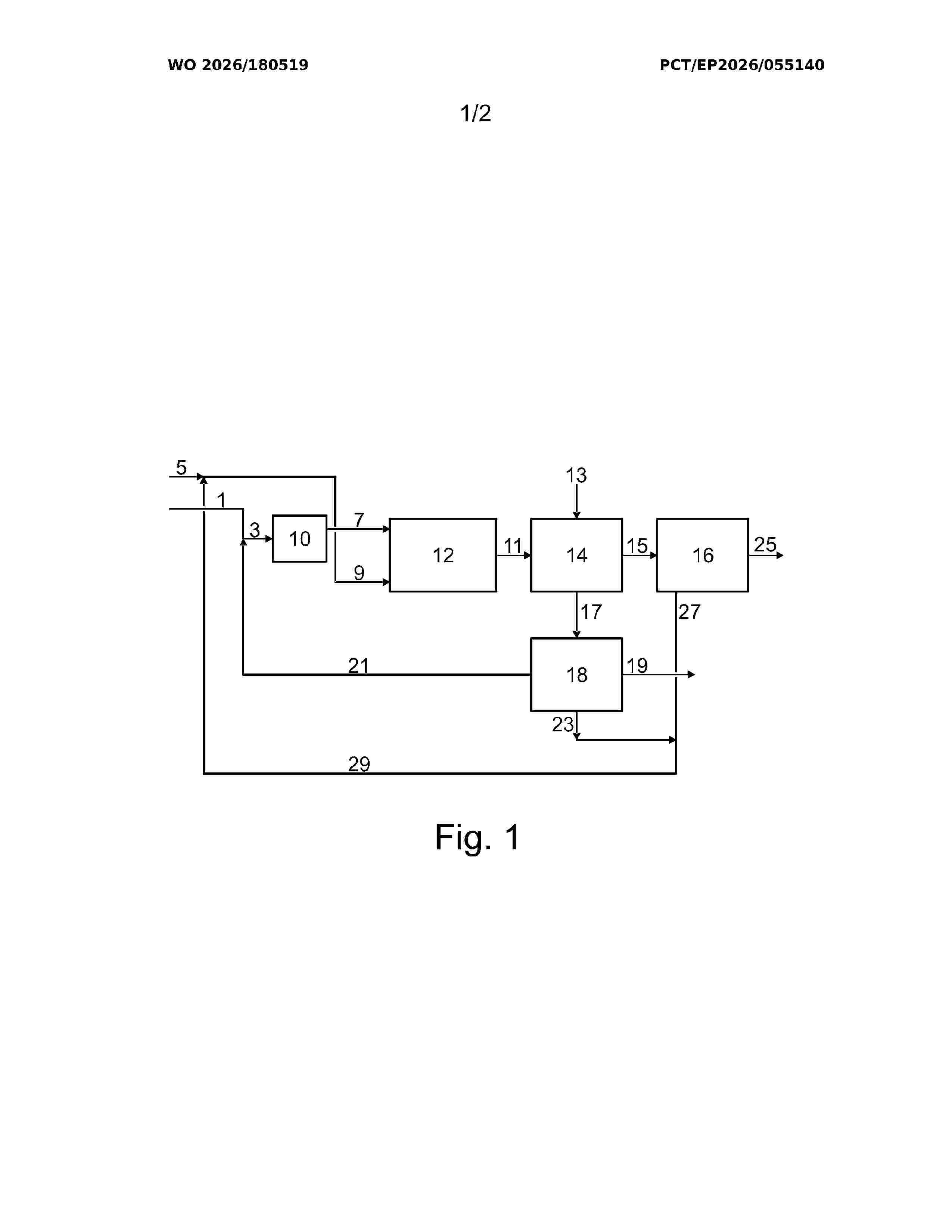
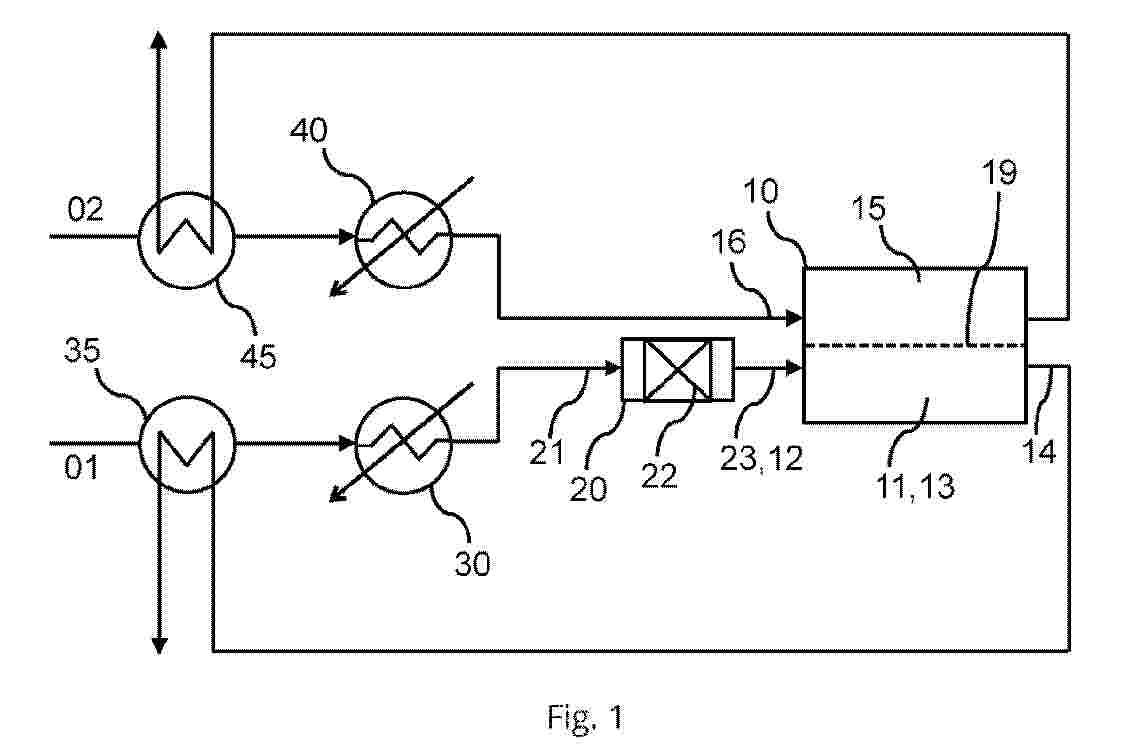
Process and plant for the production of a product gas containing nitrogen and hydrogen from ammonia, the process comprising the steps of: i) pre-cracking an ammonia feed stream to a pre-cracked process gas containing hydrogen, nitrogen, ammonia by contact with a first ammonia cracking catalyst; ii-1) non-catalytic partial oxidation of the pre-cracked process gas with an oxygen containing gas to a process gas containing nitrogen, water, nitrogen oxides and residual amounts of ammonia; ii-2) cracking of at least a part of the residual amounts of ammonia to hydrogen and nitrogen in the process gas by contact with a second ammonia cracking catalyst and simultaneously reducing the amounts of nitrogen oxides to nitrogen and water by reaction with at least a portion of the hydrogen formed during at least the pre-cracking of the ammonia feed stream, thereby producing said product gas containing nitrogen and hydrogen; iii) withdrawing the product gas. The product gas is purified downstream to a hydrogen product.
Resumen de: WO2026182942A1
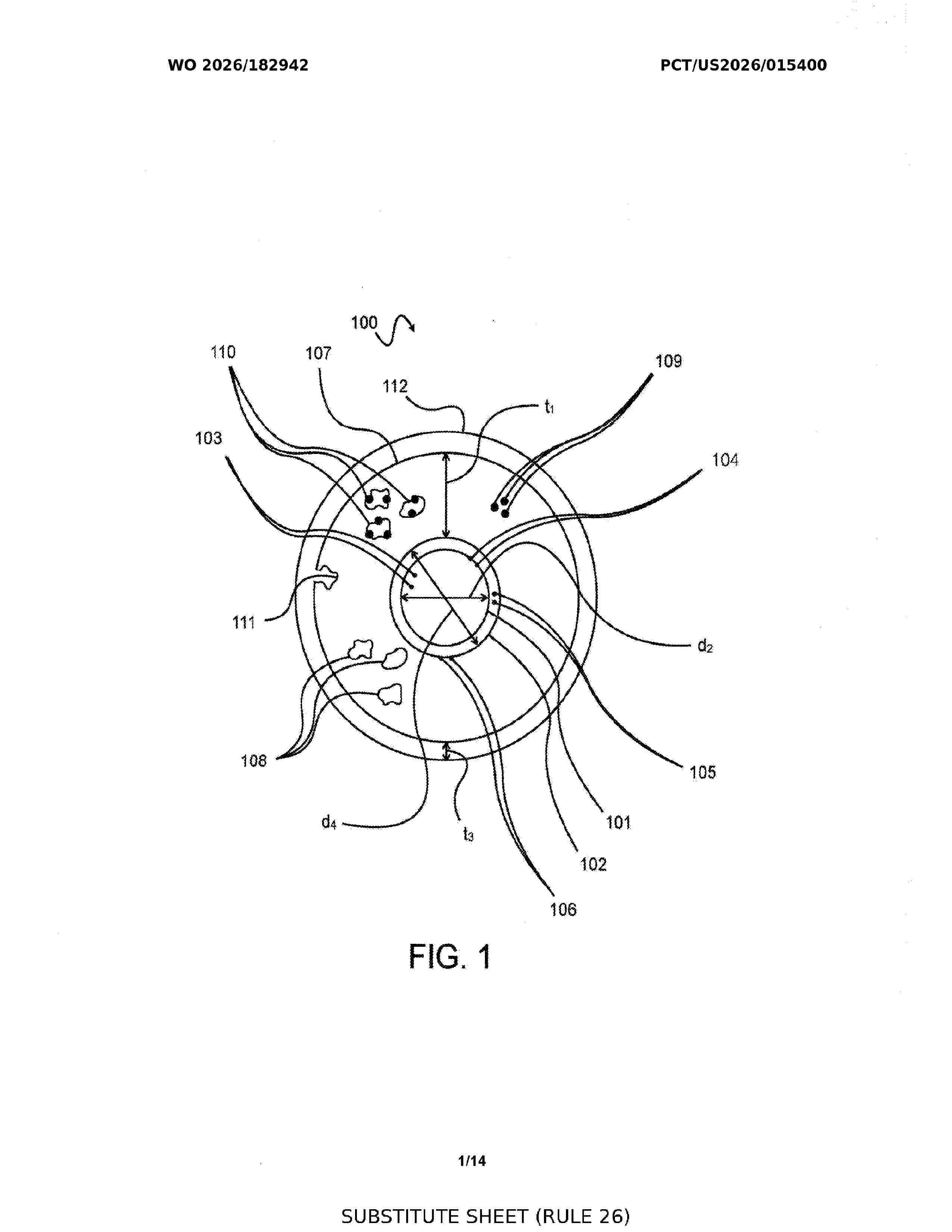
A solar-driven opto-electrolysis hydrogen production system configured to convert light and water into hydrogen is disclosed. The system includes a solar radiation collection assembly, an optical transmission network, and one or more opto-electrolysis light rods positioned within a reactor containing water. Each light rod includes an inner optical core, a cladding, and a porous layer comprising photocatalytic centers configured to generate hydrogen upon illumination. The inner optical core contains spectral conversion additives that modify incident solar radiation such that emitted wavelengths overlap an absorption band of the photocatalytic centers. In certain embodiments, the porous layer comprises a monolithic porous structure formed around the cladding with pore characteristics selected to permit diffusion of water and removal of evolved hydrogen. A plurality of light rods may be arranged in an array to enable scalable hydrogen production.
Resumen de: WO2026181447A1
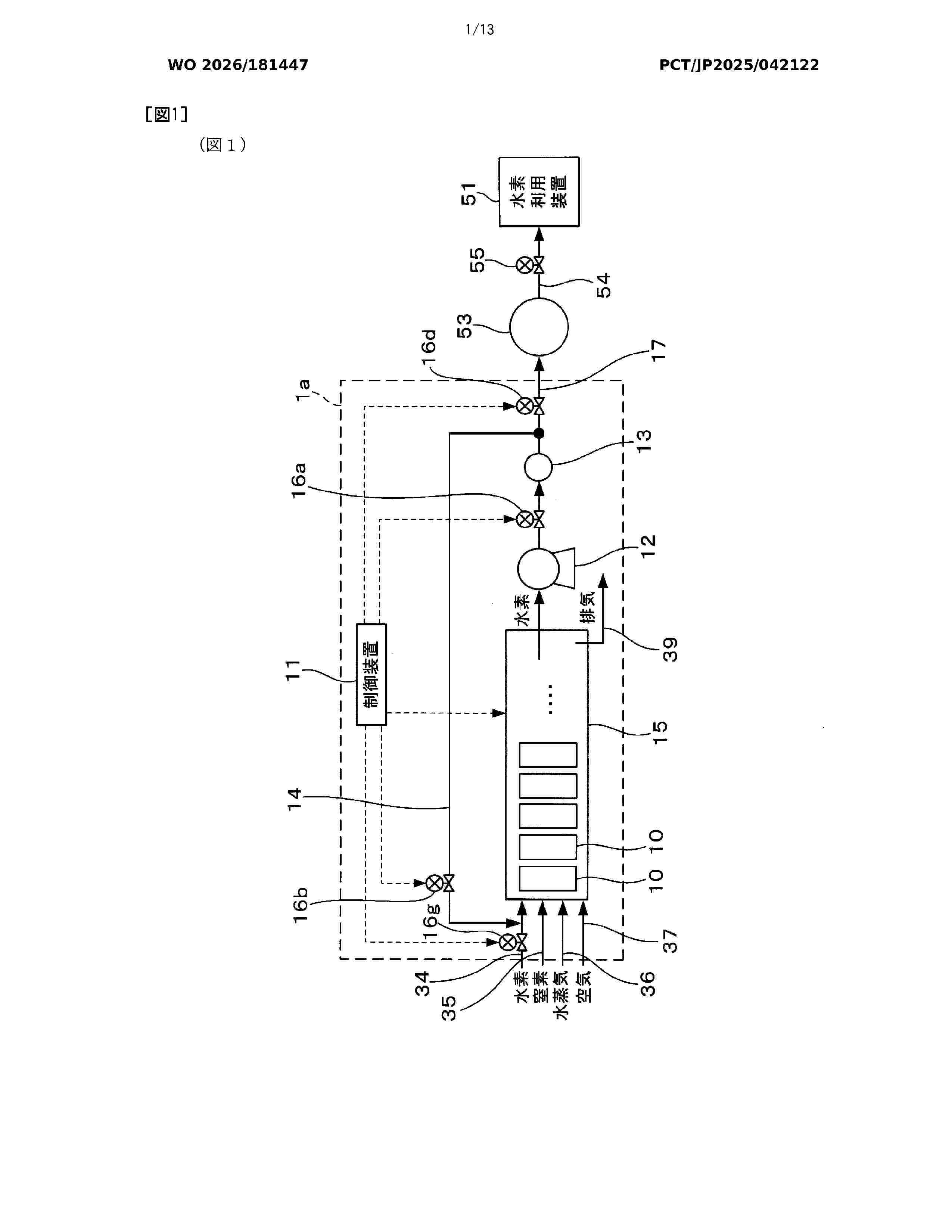
A hydrogen generation apparatus (1a) comprising a plurality of cell stacks (10) that, through electrolysis of water, generate hydrogen and oxygen as a byproduct, and a control device that controls the cell stacks (10) and controls circulation of hydrogen, wherein: the plurality of cell stacks (10) are divided into at least one firstly-started cell stack (10a) that is started firstly among the plurality of cell stacks (10) and at least one subsequently-started cell stack (10b), (10c) that is started subsequently to the firstly-started cell stack (10a); and the control device (11) is configured to be able to supply, to the subsequently-started cell stack (10b), (10c), hydrogen generated by the firstly-started cell stack (10a) when starting the subsequently-started cell stack (10b), (10c) after the firstly-started cell stack (10a) is started.
Resumen de: EP4800158A1
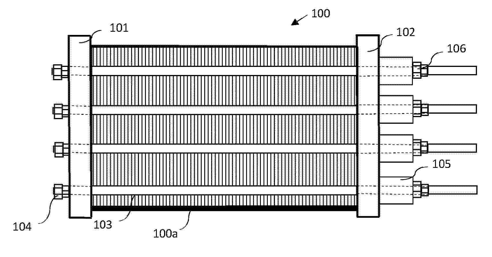
The various embodiments of the present invention disclose a pressurized alkaline electrolyser stack, comprising: a stack core (100a) comprising a plurality of electrolysis cells (200), wherein each electrolysis cell (200) comprises an anode chamber comprising an anode, a cathode chamber comprising a cathode, a diaphragm (206) separating the anode chamber and the cathode chamber, at least one cell frame (201) and at least one gasket (202). The stack core (100a) is configured to have a first stack core length L1 and a first gasket stress σ1 at a first design temperature T1 and a second stack core length L2 and a second gasket stress σ2 at a second design temperature T2. The first design temperature T1 is at least 80 degrees Celsius and the second design temperature T2 is less than 30 degrees Celsius. A stack core length difference dL = L1-L2 is between 0 to 20 millimeters, and a gasket stress difference dσ =σ1-σ2 is between 0 to 20 MPa.
Resumen de: EP4800161A1
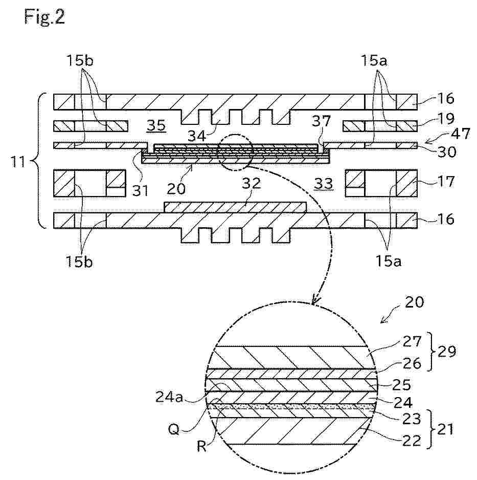
Provided is a technique for suppressing occurrence of cracking in a solid electrolyte layer. A solid oxide electrolysis cell includes an air electrode containing a complex oxide having a perovskite structure, a fuel electrode, and a solid electrolyte layer disposed between the air electrode and the fuel electrode. In an interface region of the fuel electrode, which region extends 5 µm from the interface between the fuel electrode and the solid electrolyte layer, the Al content is 1 ppm or greater and 100 ppm or less.
Resumen de: EP4545476A1
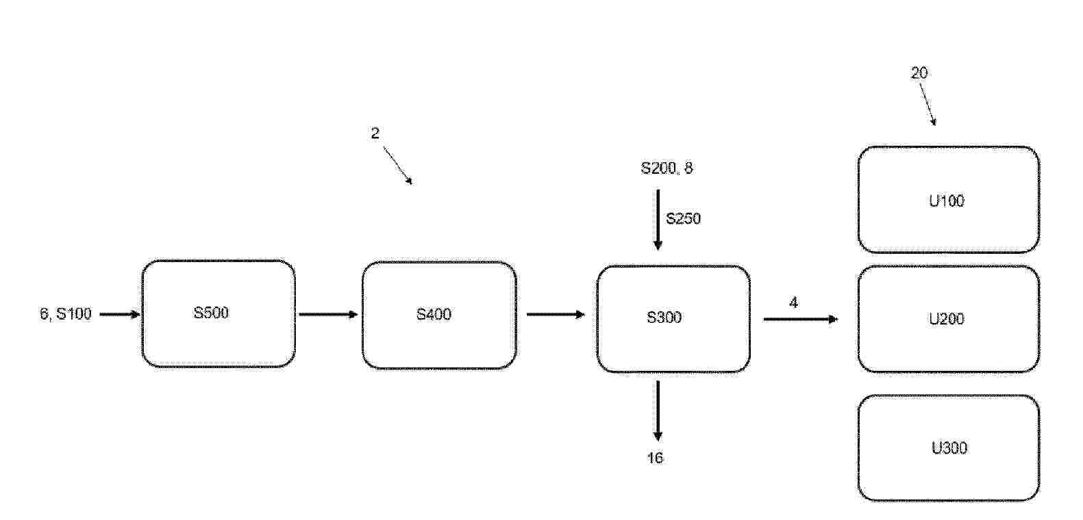
Process (2) for the production of an enhanced fuel gas (4) containing at least hydrogen gas from a fuel stream, in particular from an ammonia fuel stream (6). Said process comprises the following steps:- providing the fuel stream (6) (S100);- providing a condensable medium (8), preferably water steam (8), to a cracker unit (10);- at least one step of performing an endothermic cracking reaction of the fuel stream (6) in the cracker unit comprising at least one catalyst suitable for cracking said fuelstream (6), so as to produce an at least partially cracked fuel stream as said enhanced fuel gas (4) (S300); and- condensing at least partially said condensable medium (8) to provide said heat for the endothermic cracking reaction of the fuel stream (6).
Resumen de: WO2025088418A1
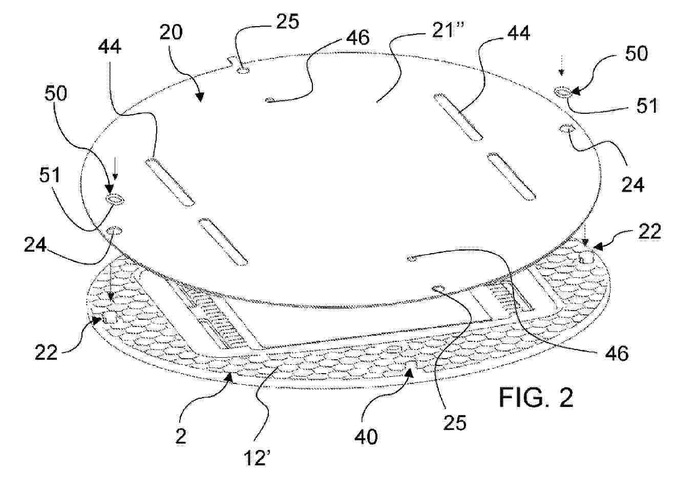
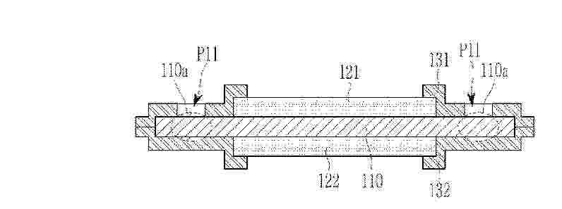
Electrochemical device (1), preferably of the electrolyser type for hydrogen production, characterised by comprising: - at least one support frame (2), with a substantially laminar development, which is provided with at least one seat (3) for an electrochemical module (10), said support frame (2) comprising a first face (12') and a second face (12") which are opposite to each other, at least one electrochemical module (10) which is mounted in said at least one seat (3) and which comprises a separation membrane interposed between two electrodes, respectively between an anode and a cathode, at least one bipolar plate (20) for applying/transferring electrical energy to the electrodes of said at least one electrochemical module (10), said bipolar plate (20) comprising a first surface (21') and a second surface (21") which are opposite to each other, said bipolar plate (20) being superimposed on said support frame (2) and being configured so that the first surface (21') of said bipolar plate (20) rests, at least in part, on a first face (12') of said support frame (2).
Resumen de: EP4800157A1
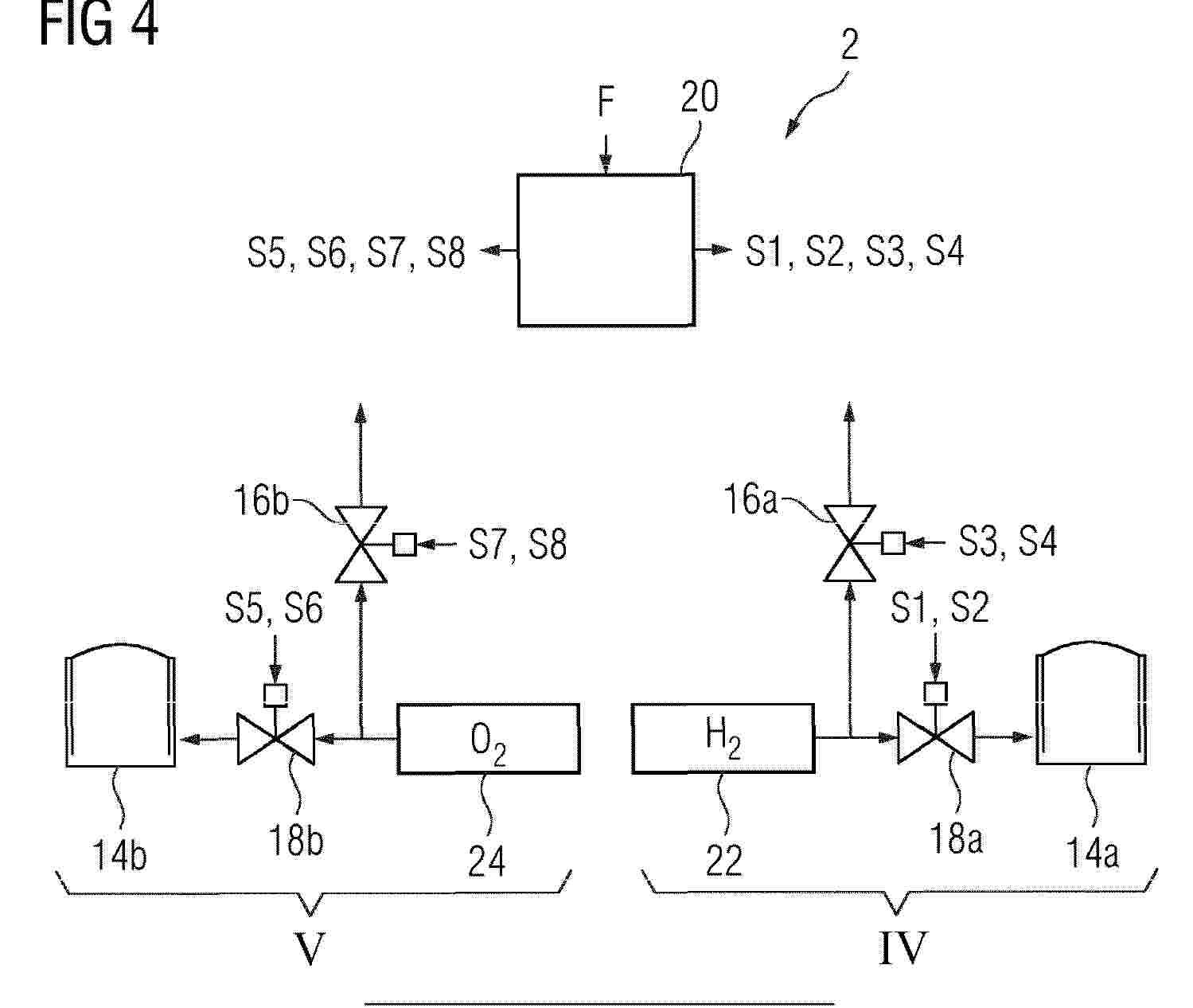
0001 Method of operating an electrolysis system (2) wherein the method comprising the step of: (S100) providing a control signal (S5) to a product valve (18b) on the oxygen-side (V) of the electrolysis system (2) to keep the product valve (18b) open in order to buffer oxygen provided by the electrolysis system (2) in a buffer tank (14b) on the oxygen-side (V) in normal operation of the electrolysis system (2).
Resumen de: EP4800000A1
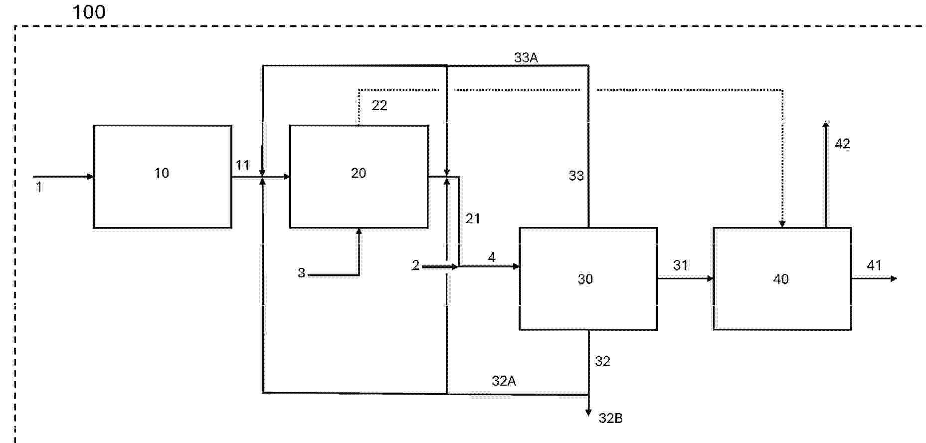
The invention relates to an methanol plant comprising: a CO2-rich feed, a hydrogen-rich feed, a boiler feed water stream, a CO2-electrolysis section arranged to electrolyse at least a portion of the CO2-rich feed to output a mixed stream, a heat exchange section arranged to heat exchange at least a portion of the first mixed stream so as to output a cooled mixed stream and a steam stream, a methanol synthesis loop arranged to receive at least a portion of the cooled mixed stream and at least a portion of the hydrogen-rich feed and to output a raw methanol stream, a purge gas stream, and a flash gas stream, and a methanol upgrading section, wherein the steam stream is arranged to provide heat energy for one or more components of the methanol upgrading section. At least a portion of the purge gas stream is arranged to be recycled to the CO2-rich feed, and/or at least a portion of the flash gas stream is arranged to be recycled to at least one of: the mixed stream and the cooled mixed stream. The invention also relates to a method for converting CO2 to methanol.
Resumen de: EP4800782A1
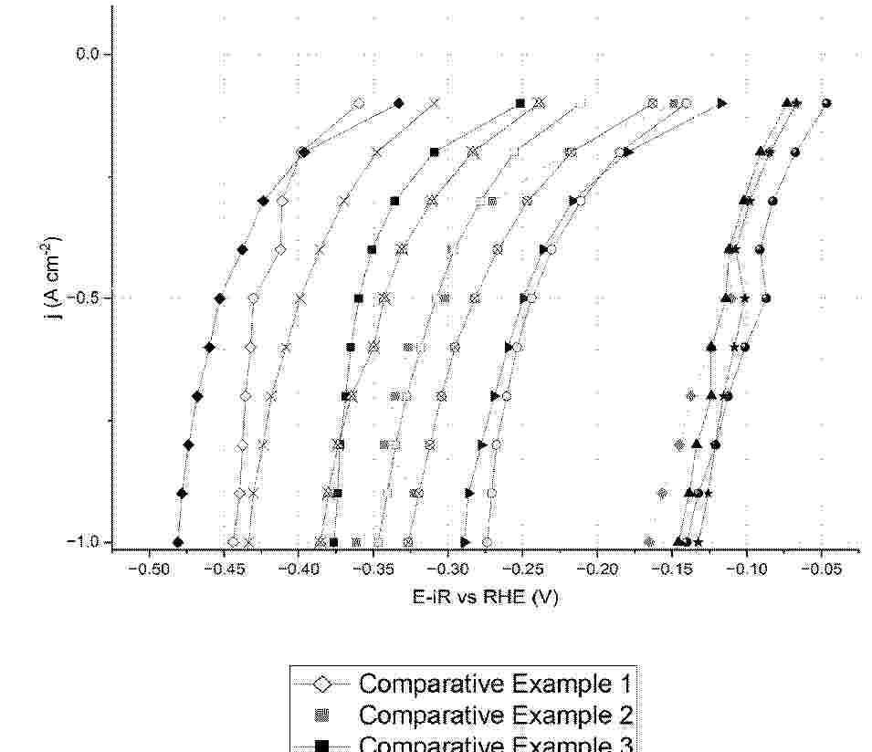
The present invention relates to a method for the preparation of a cathode for alkaline water electrolysis of water particularly useful in the reaction of hydrogen evolution comprising nickel, iron and/or cobalt oxide and a noble metal based on the self-combustion of a precursor mixture deposited or coated on the surface of an electrode carrier. The invention also relates to an electrode obtainable according to said method and to its use as cathode in water electrolysis, in particular in alkaline water electrolysis.
Resumen de: EP4800156A1
Provided is a membrane-electrode assembly for a water electrolysis cell, including: a polymer electrolyte membrane having an active area and an inactive area surrounding the active area; a hydrogen generation electrode positioned on a first surface of the active area of the polymer electrolyte membrane; an oxygen generation electrode positioned on a second surface of the active area of the polymer electrolyte membrane; a first subgasket disposed on a first surface of the inactive area of the polymer electrolyte membrane and surrounding the hydrogen generation electrode; and a second subgasket disposed on a second surface of the inactive area of the polymer electrolyte membrane and surrounding the oxygen generation electrode, wherein the first subgasket has a first window accommodating the hydrogen generation electrode, and a first water supply path surrounding the first window and exposing the inactive area of the polymer electrolyte membrane.
Resumen de: WO2025087866A1
The invention relates to a method of operating a solid oxide electrolysis cell (SOEC) stack for producing hydrogen, and a system for carrying out the method, said SOEC stack comprising at least one solid oxide electrolysis cell (SOEC), said at least one SOEC comprising an electrolyte layer interposed between a fuel-side and an oxy-side, the method comprising transient operation, in which the transient operation comprises: - operating the SOEC stack under open-circuit voltage (OCV); - providing a feed gas comprising ammonia; - supplying at least a portion of said feed gas comprising ammonia to a guard bed reactor, said guard bed reactor comprising a catalyst active in the cracking of ammonia to nitrogen and hydrogen; and withdrawing from said guard bed reactor a forming gas comprising nitrogen and hydrogen; - supplying at least a portion of the forming gas comprising nitrogen and hydrogen to the fuel-side of the at least one of the solid oxide electrolysis cells (SOECs) of the SOEC stack; and withdrawing from said at least one of the SOECs of the SOEC stack, a first fuel-side exit gas.
Resumen de: WO2025087865A1
The present invention relates to a guard bed reactor for silicon removal, a solid oxide electrode system for producing hydrogen comprising a guard bed reactor for silicon removal, a method of operating the system to produce hydrogen and a use of the guard bed reactor for silicon removal for depleting a stream of steam from volatile silica species.
Resumen de: WO2025090834A1
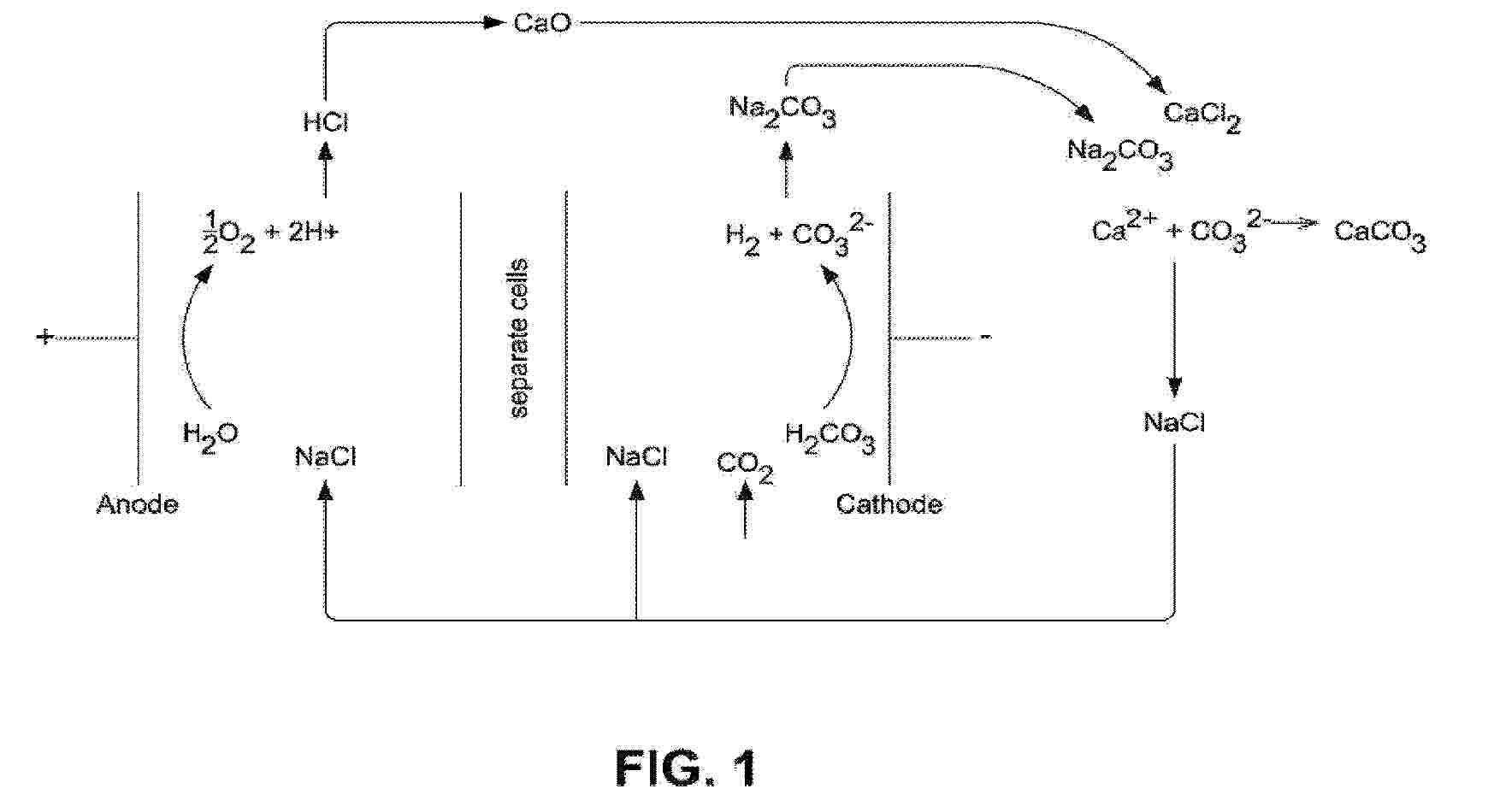
Disclosed herein are systems and methods for tandem hydrogen (H2) production and carbon dioxide (CO2) capture. For example, described herein are methods comprising tandem H2 production and CO2 capture and conversion to a carbonate mineral. In some examples, the method is an electrochemical method. In some examples, the method comprises dissolving CO2 in water and applying an electrochemical potential sufficient to drive the H2 evolution reaction, thereby producing H2 and CO3 2-. In some examples, the methods further comprise contacting the CO3 2- with a cation to thereby form an insoluble carbonate compound.
Resumen de: EP4800057A1
0001 The present invention relates to a reinforced composite polymer electrolyte membrane having assured mechanical, structural, and thermal stability.
Resumen de: EP4799916A2
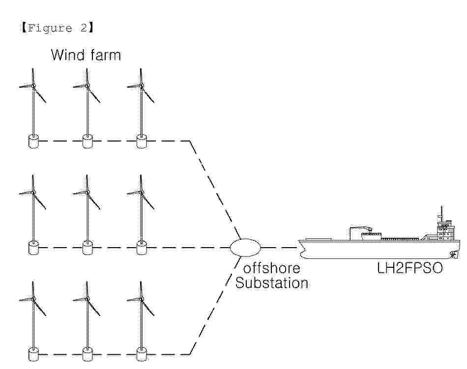
The present invention relates to an apparatus and method for producing, storing, and transferring hydrogen. According to the present invention, in order to address the problems of conventional systems and methods for producing, storing, and transferring marine green hydrogen, which are configured with a fixed structure in a small-scale offshore wind power generator on a coast or in a shallow sea area with a shallow depth of water, and thus, have low efficiency due to the difficulty in mass production of hydrogen, and a large storage space is occupied when the produced hydrogen is converted into a compressed gas form, and when the produced hydrogen is converted into ammonia, additional energy is required to extract the hydrogen again and there is a risk of environmental pollution and casualty in the event of an outflow accident, provided is a marine platform for producing, storing, and transferring marine green hydrogen, which is configured such that marine green hydrogen is produced through a floating marine structure configured to produce marine green hydrogen using electricity produced using renewable energy from the ocean, and simultaneously, the produced marine green hydrogen is stored, transferred, and offloaded through a single offshore platform (FPSO), thereby being possible to easily construct a large-scale production facility capable of producing, storing, and transferring marine green hydrogen without greenhouse gas emission on the basis of eco-friendly energy.
Resumen de: EP4800162A2
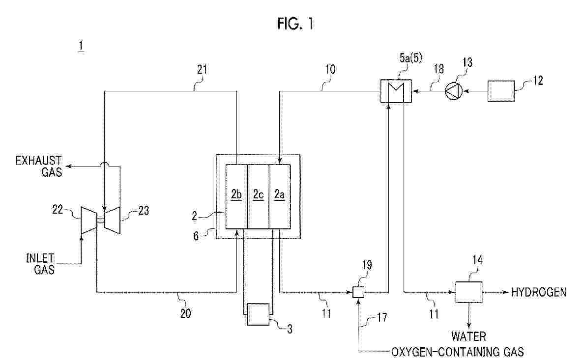
The hydrogen production system comprises a solid oxide electrolysis cell (SOEC) that electrolyzes steam, a steam discharge line through which the steam discharged from the hydrogen electrode of the SOEC passes, a main heat exchanger that generates the steam by heating supply water through heat exchange between the supply water and the steam passing through the steam discharge line, a combustor that combusts a part of hydrogen contained in steam discharged from a hydrogen electrode, a superheater that exchanges heat between the steam generated in the main heat exchanger and the combustion gas generated in the combustor, a gas discharge line through which an exhaust gas discharged from an oxygen electrode of the SOEC passes, a steam bleeding line that allows the steam discharge line and the combustor to communicate with each other, and an exhaust gas bleeding line that allows the gas discharge line and the combustor to communicate with each other.
Resumen de: US2020032688A1
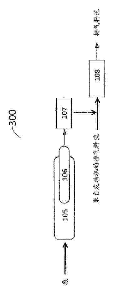
0001 Systems for abatement of pollutants in an exhaust gas stream of an internal combustion engine including a hydrogen injection article configured to introduce hydrogen upstream of a catalytic article are effective for the abatement of carbon monoxide and/or hydrocarbons and/or nitrogen oxides. The introduction of hydrogen may be intermittent and/or during a cold-start period.
Nº publicación: KR20260131012A 31/08/2026
Solicitante:
YEUNG TSUN KWAN [CN]
\uC601 \uCD98\uCF74
Resumen de: US20250297366A1
A Microwave Plasma-enhanced Chemical Vapor Deposition (MPCVD) Device is provided. The MPCVD device comprises a reacting chamber and a gas generator. The reacting chamber contains a substrate holder. The gas generator provides hydrogen to the reacting chamber. The purity of the hydrogen is higher than 4N. The reacting chamber is configured to facilitate a MPCVD process, and the gas generator is at the site of the MPCVD process.
 BOPI
BOPI
 Sede Electrónica