Si deseas distinguir tus productos, servicios o ambos de los de otra empresa, es posible que necesites una marca o nombre comercial. Descubre qué son, en qué consiste su procedimiento de registro y qué implica.

Información sobre los plazos de presentación de solicitudes de transformación de marcas de la Unión Europea en marca nacional española. Más información


Si tienes un nuevo dispositivo, producto o procedimiento que resuelva un problema técnico o tenga una ventaja práctica, existen distintas formas de protegerlo en España y en otros países. Descubre cómo hacerlo.

¿Tu innovación reside en la estética, la ornamentación o la apariencia de tu producto? Protégela mediante un diseño industrial. Descubre qué derechos confiere el registro y cómo realizar la tramitación.

Las indicaciones geográficas protegen el nombre de un producto originario de una zona geográfica, a la cual le debe una determinada calidad, reputación u otra característica. Descubre qué son, en qué consiste su procedimiento de registro y qué beneficios conceden.

Las patentes publicadas en todo el mundo son una valiosa fuente de información científica, técnica y comercial.

Si eres emprendedor/a o una empresa y quieres potenciar y mejorar la rentabilidad de tu negocio protegiendo de forma adecuada los activos intangibles de tu organización, en este espacio encontrarás lo necesario.


 130
resultados
130
resultados
 Última actualización
26/06/2026 [09:49:00]
Última actualización
26/06/2026 [09:49:00]


 Resultados 50 a 75 de 130

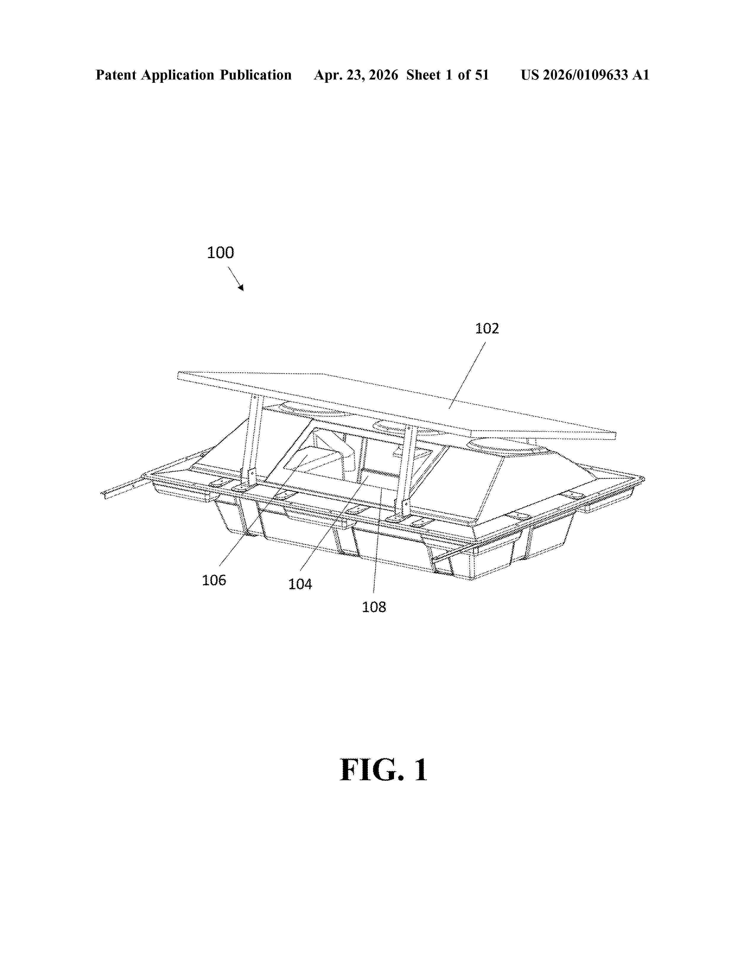
Resumen de: US20260109633A1
0000 Disclosed herein are devices, systems, and methods for water aeration and/or circulation, including, but not limited to, floating, onboard renewable energy-powered aeration for aquaculture ponds and/or other man-made and/or natural bodies of water (e.g., tanks, farm ponds, and reservoirs). In at least one embodiment, an aeration system has one or more photovoltaic (PV) panels to provide power to the aeration system. In at least one embodiment, the aeration system captures wind energy as an optional secondary power source. The aeration system may be either a battery-power or a direct-power system. The aeration system may also provide programmable settings. The system can be modular and scaled and/or customized to fit user needs. The aeration system may also include one or more float modules having an internal cavity, one or more pontoons and/or pontoon accessories for blocking and/or directing air and/or water flow, and/or one or more novel diffusers.

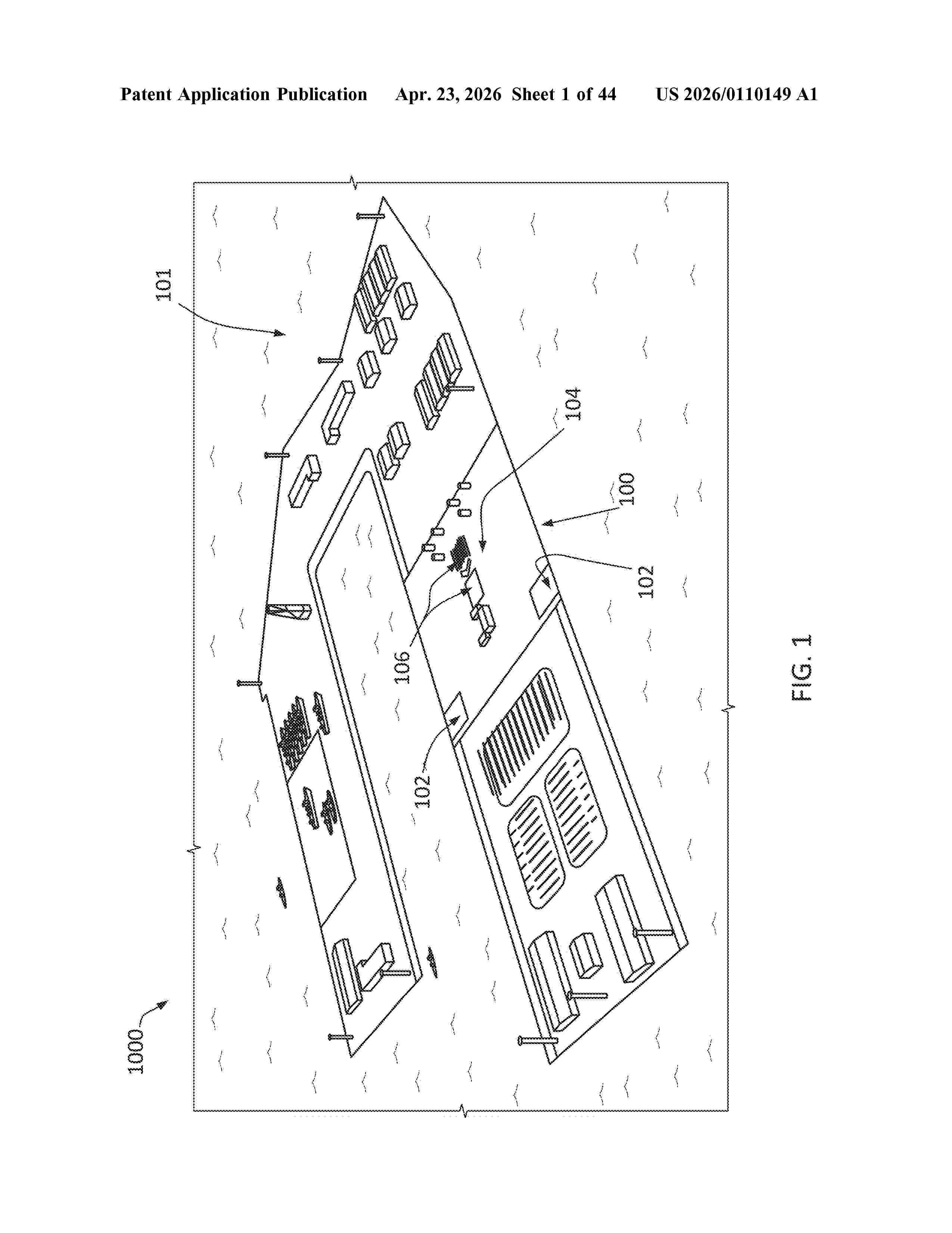
Resumen de: US20260110149A1
0000 Systems and methods for assembling, launching, retrieving, and maintaining marine vessels, structures, renewables and equipment, either floating or fixed bottom, are disclosed. The systems include a floating dock, either extendable modular or monolithic, made of steel or concrete or combination thereof, and including a lift platform which may be locked to the dock to create a combined structure. The floating dock can be selectively supported by the seabed.
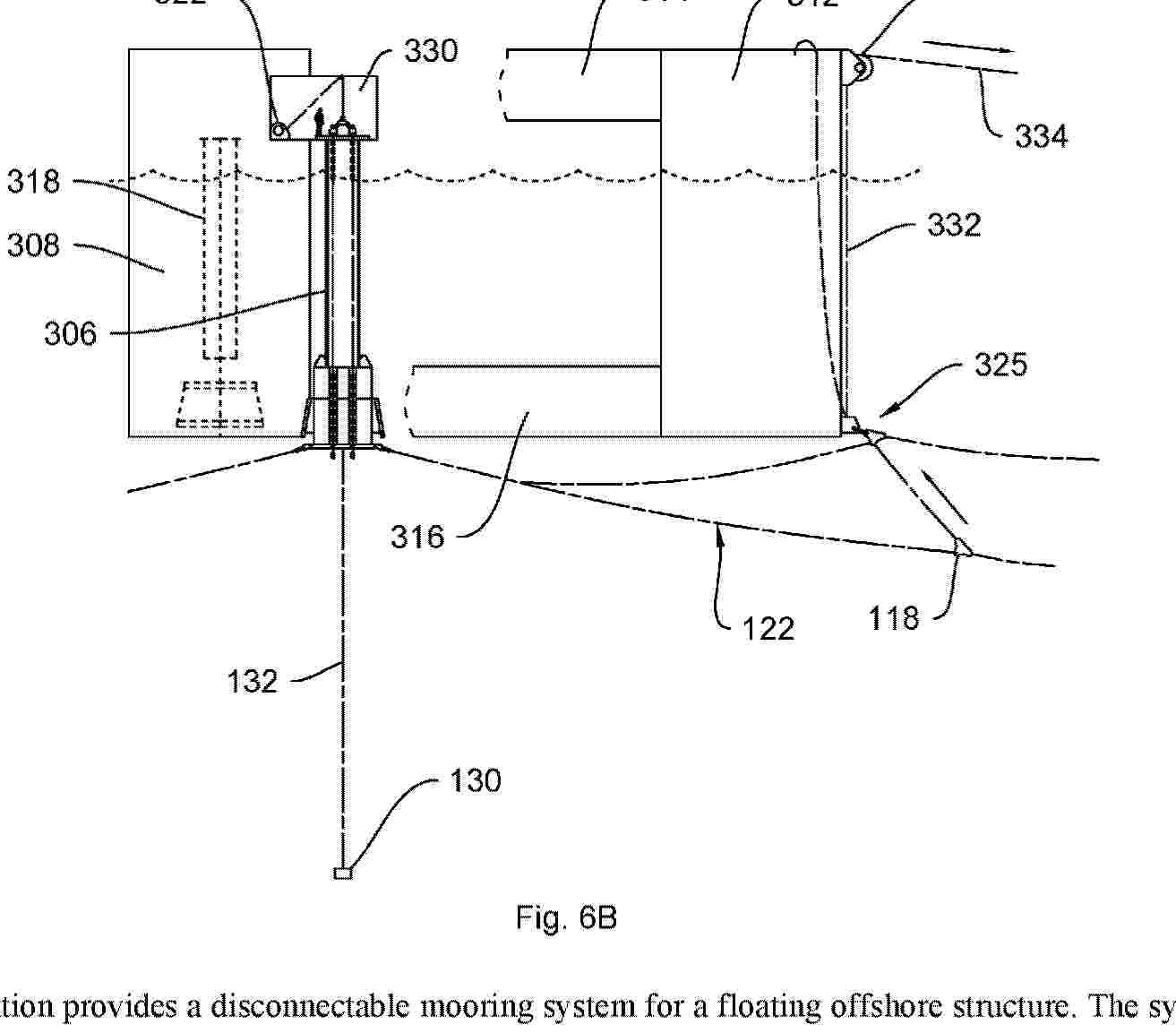
Resumen de: AU2024354901A1
The invention provides a disconnectable mooring system for a floating offshore structure. The system may comprise: a buoy comprising a connector which enables connection and disconnection of the buoy from the floating structure. The system has a disconnected configuration in which the buoy is not connected to the floating structure and the buoy at least partially supports a dynamic riser conduit above the seabed. The system has a connected configuration in which the buoy is connected to the floating structure; and wherein the system is configured to enable pull-in of the buoy to the connected configuration and pull-in of the dynamic riser to a connection position. Aspects of the invention include related pull-in sequences, independent through connection of first and second dynamic riser conduits, and conductive coupling of a dynamic riser conduit to a floating structure. Further aspects of the invention include related rapid / emergency disconnect systems and methods, use a clump weight in an installation sequence, connection structures and buoy configurations, and rope connectors.
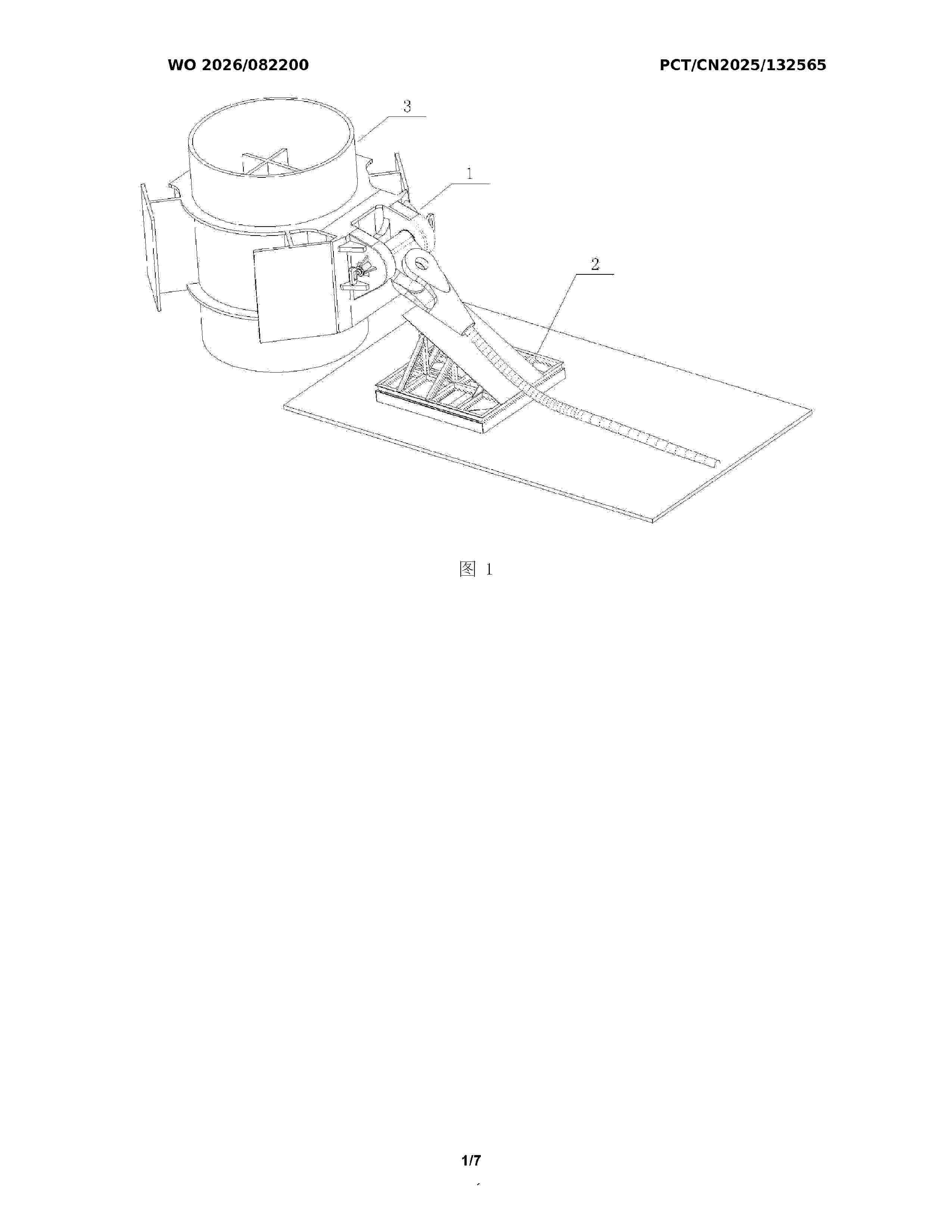
Resumen de: WO2026082200A1
The present invention relates to the technical field of mooring connection of tension-leg floating wind turbine platforms. Disclosed is a pile foundation connection device for a tension-leg floating wind turbine platform. The pile foundation connection device comprises a bottom connection mechanism and a steel cable protection mechanism, wherein the bottom connection mechanism comprises a welding back plate, a tongue plate is provided on the welding back plate, the upper end of the tongue plate is connected to a steel cable socket by means of a pin shaft, and a steel cable is connected to the steel cable socket, such that the steel cable is capable of two rotational degrees of freedom; both ends of the tongue plate are locked and fixed by means of locking mechanisms; and the steel cable protection mechanism is located on one side of a pile foundation, and the steel cable is placed on the steel cable protection mechanism after the steel cable is connected, so as to prevent over-bending damage to the steel cable when same is pre-laid on the seabed. The present invention features a simple structure, a reliable performance and convenient operation, and can adapt to underwater quick connection; and the entire operation process only requires the assistance of one ROV, thereby simplifying the tie-back installation procedure of mooring lines and anchoring devices for a tension-leg wind turbine platform, and reducing the mooring and installation costs of the tension-leg wind turbine p
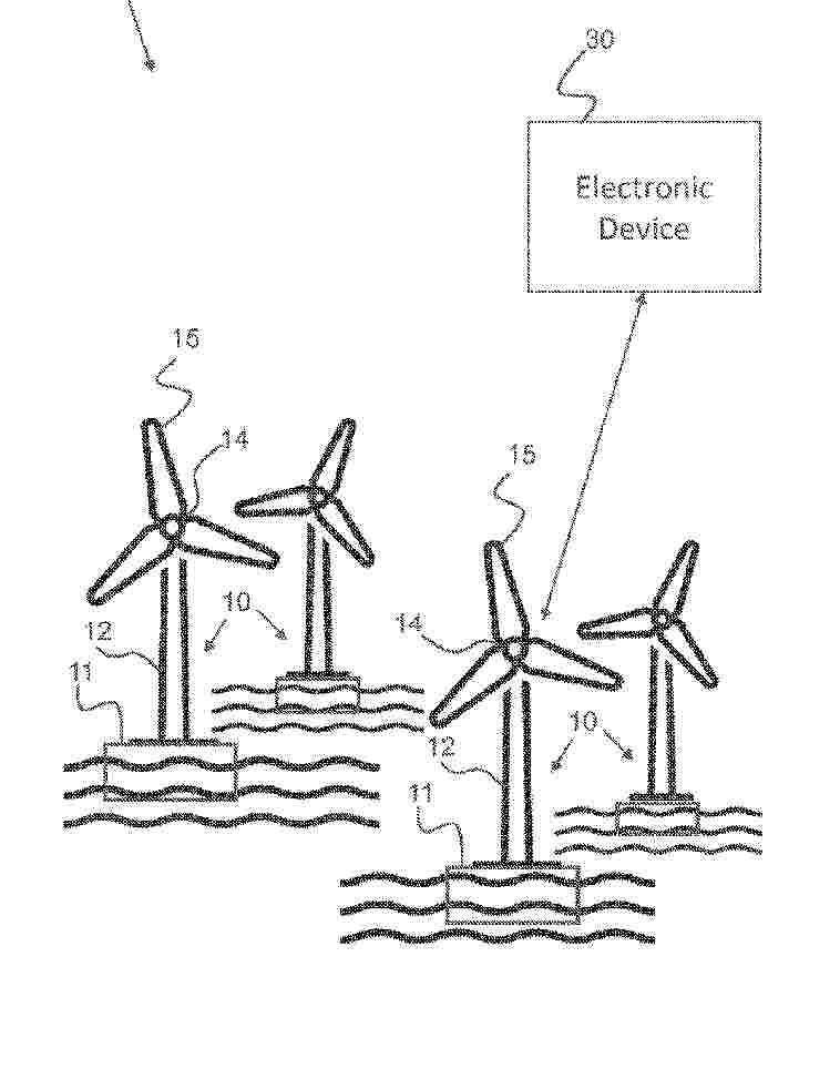
Resumen de: WO2024255979A1
Disclosed is a method for controlling a floating wind turbine system. The floating wind turbine system comprises a floating platform, a tower mounted to the floating platform and a nacelle. The method comprises receiving, from one or more sensors of the floating wind turbine system, a signal indicative of a vertical acceleration of the floating wind turbine system. The method comprises determining, based on the received signal, a sea state parameter indicative of an oscillation of the vertical acceleration. The method comprises controlling the floating wind turbine system based on the sea state parameter.
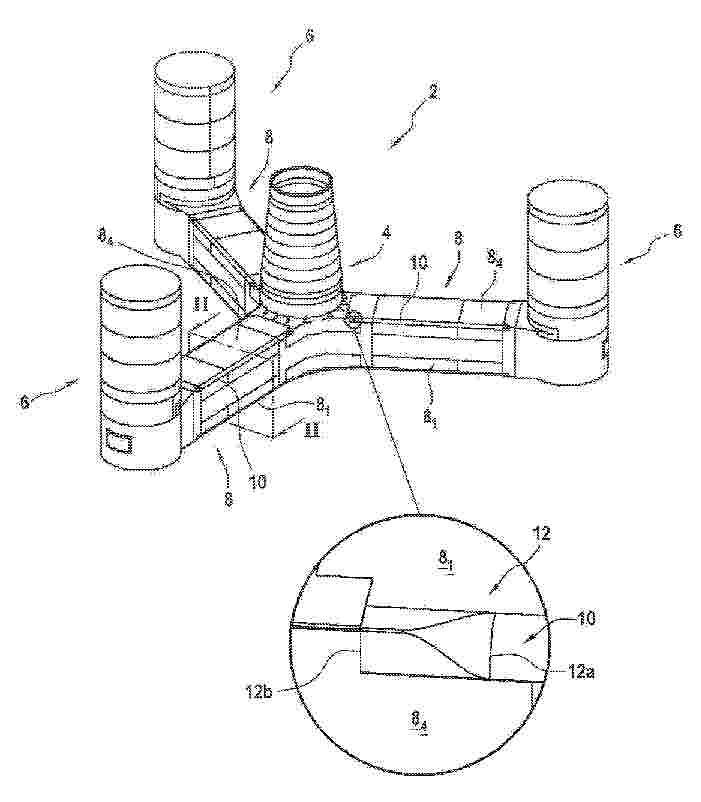
Resumen de: WO2024256782A1
The invention relates to a semi-submersible float (2) for an offshore wind turbine, comprising at least three vertical columns (4, 6), one of which is intended to receive a wind turbine mast, the vertical columns being connected together by pontoons (8) each formed by a plurality of planar panels (81 to 84) which are assembled together at edges (10) extending longitudinally between two columns, the edges of the pontoons being rounded and connected at each of their longitudinal ends to a column via a transition piece (12).
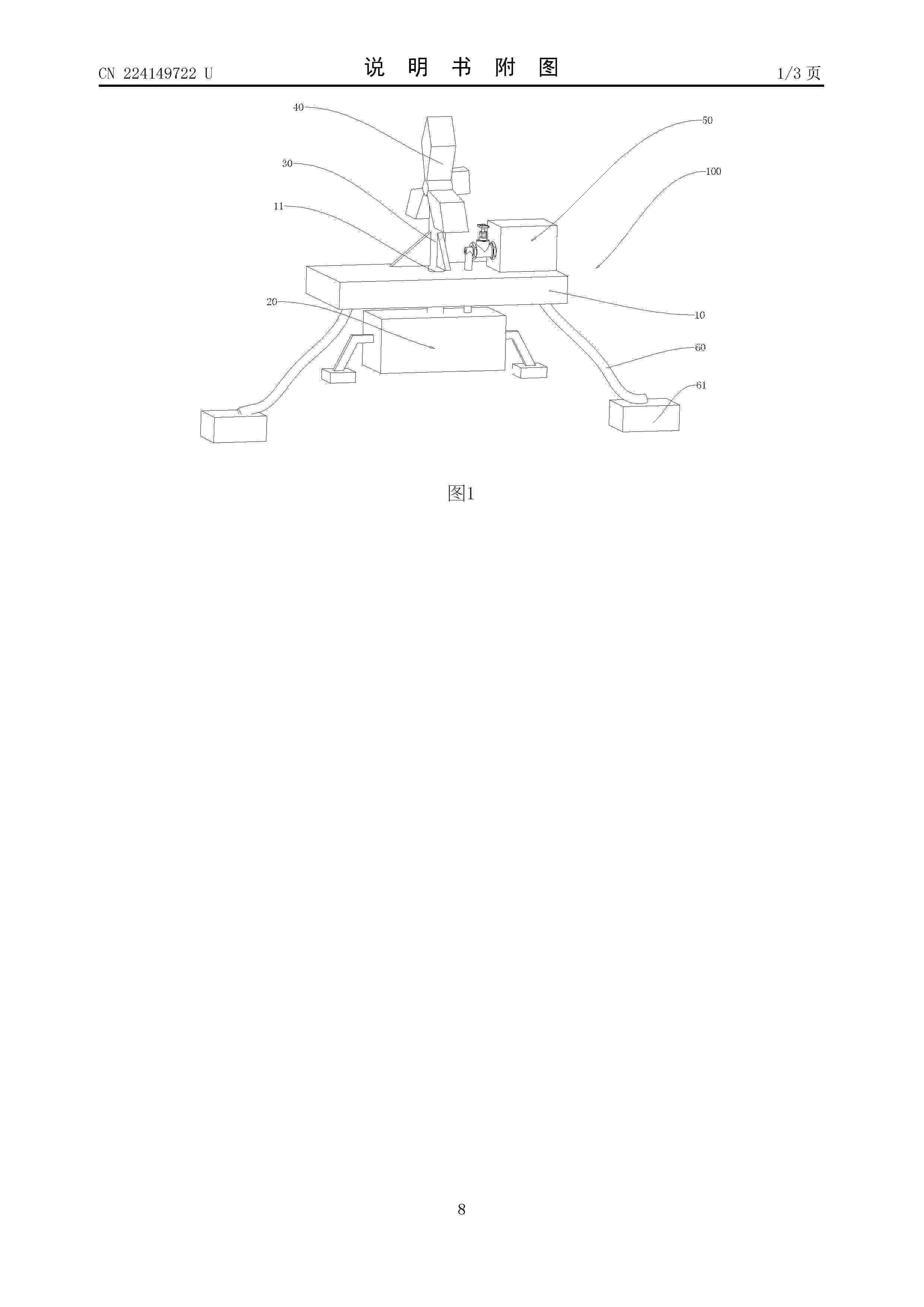
Resumen de: CN224149722U
The utility model discloses a device capable of regulating and controlling the height of a floating type offshore wind generating set in real time, which comprises a supporting platform, a buoyancy component, a supporting rod, a fan and a power component, wherein the buoyancy component, the supporting rod and the fan are arranged on the supporting platform; the buoyancy assembly comprises a floating cabin arranged on the supporting platform and a ventilation pipe communicating the floating cabin with the power assembly, the floating cabin is connected with the supporting rod, a water through hole is formed in the floating cabin, the power assembly comprises an air pump, and an air outlet of the air pump is communicated with the ventilation pipe. When wind waves on the sea change, air is pumped or conveyed into the floating cabin through the air pump, so that the ratio of the air content to the water content in the floating cabin is changed, the height of the draught fan relative to the sea level is adjusted according to the magnitude of the wind waves, and the height of the draught fan relative to the sea level can adapt to the change of wind power; therefore, the stability of the fan is improved.
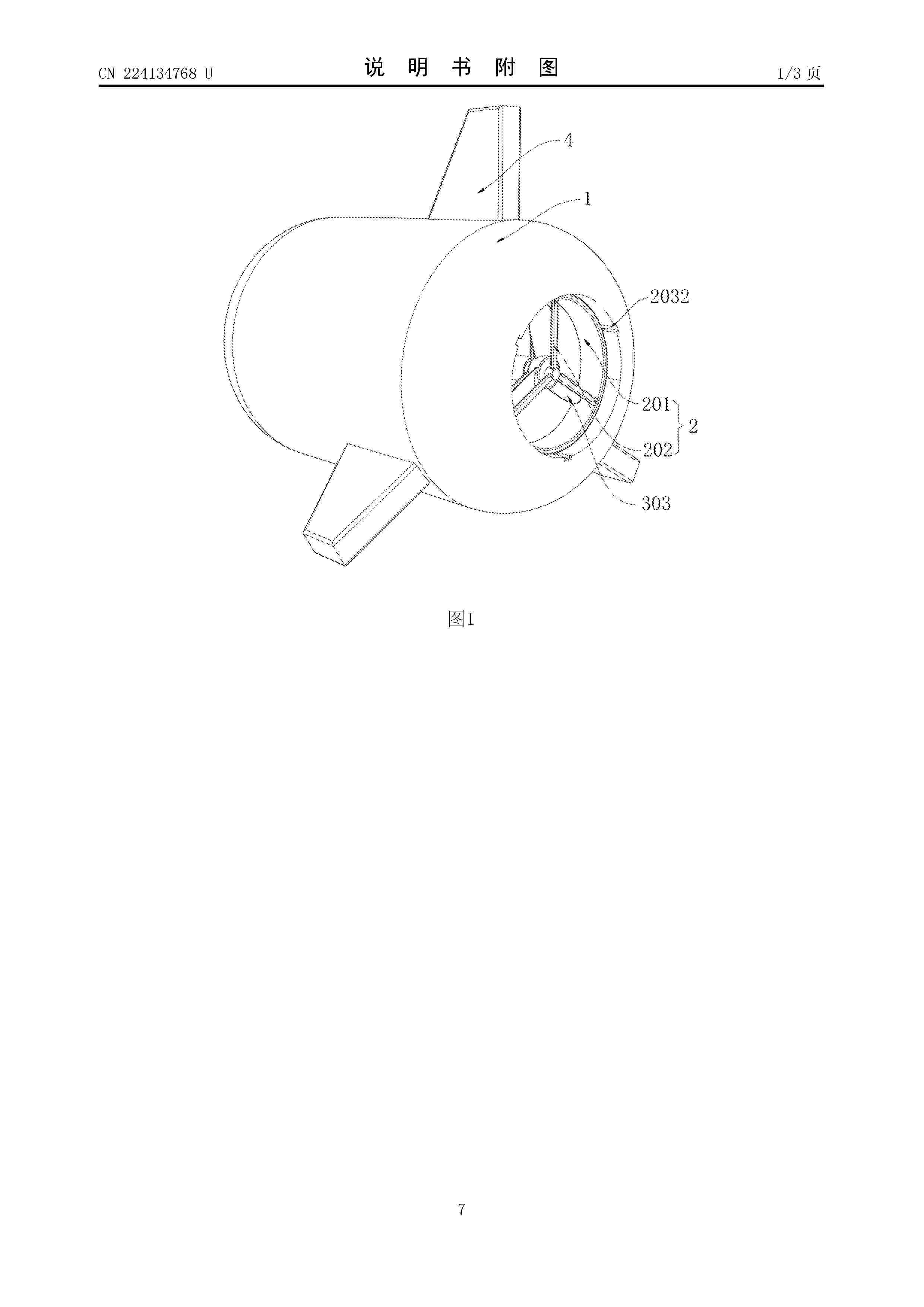
Resumen de: CN224134768U
The utility model relates to the technical field of electric power engineering, and discloses a portable helium floating power generation device which comprises a machine body, a mounting mechanism is arranged on the right side of the inner wall of the machine body and used for conveniently and rapidly mounting and dismounting equipment, and a power generation mechanism is arranged on the left side of the mounting mechanism and used for conveniently and rapidly mounting and dismounting the equipment. The power generation mechanism is used for converting wind energy into electric energy, the mounting mechanism comprises a mounting ring, the outer wall of the mounting ring is slidably connected with the right side of the inner wall of the machine body, a plurality of first supporting rods are fixedly connected to the right side of the inner wall of the mounting ring, and clamping assemblies are arranged at the ends of the first supporting rods. A guide assembly is arranged on the right side of the inner wall of the machine body close to the edge. The guide block is pushed into the second guide groove, the installation ring is rotated to enable the guide block to slide to the position of the spring column along the inner wall of the groove, the clamping groove pushes the sliding block and the guide block to be clamped into the spring column, the pressing block is pulled, the dismounting steps are simplified, and carrying and using are convenient.
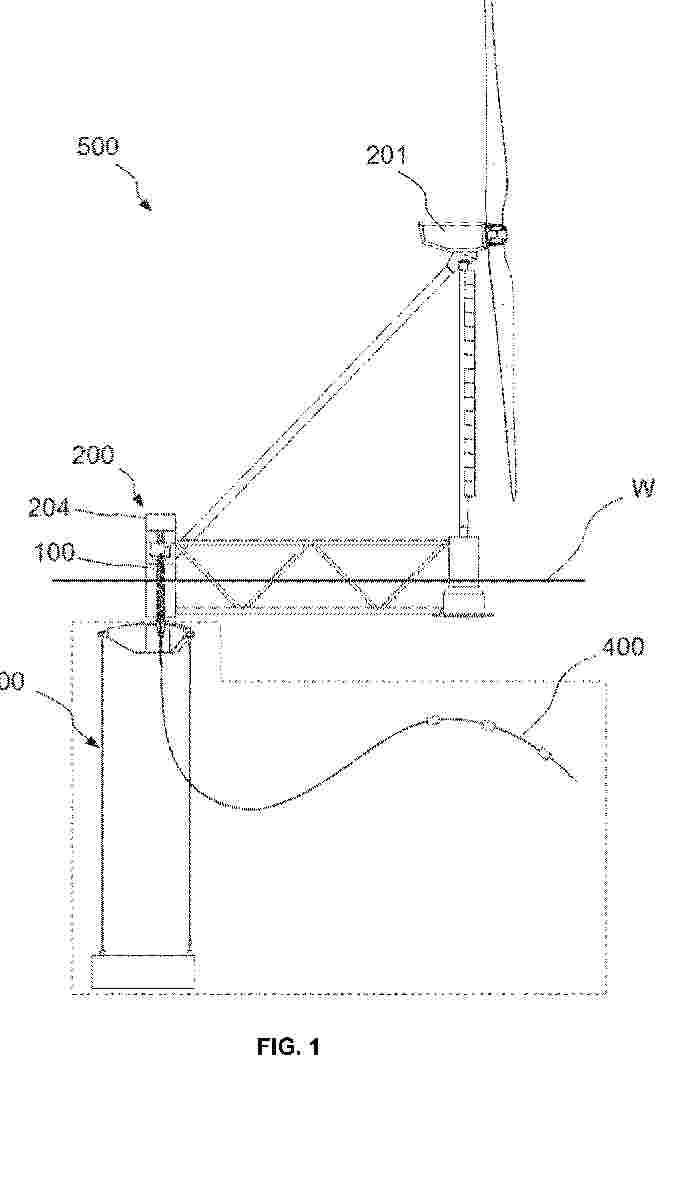
Resumen de: AU2024356626A1
A connecting system (100) for connecting a weathervaning floating offshore support structure (200) of a wind turbine (201) to a pre-laid mooring system (300), the connecting system (100) comprising: - a turret element (1) comprising: a base (2) for being solidly connected to the pre-laid mooring system (300); a support element (3) comprising a switchgear (31) connectable to one or more submarine cables (400) and connectable to receive a power generated by the wind turbine (201); a columnar body (4) extending from the base (2) to the support element (3), and comprising an inner passage (41); and a bearing system (5) configured to rotatably connect the turret element (1) to the weathervaning floating offshore support structure (200); and - a slip-ring connector (6) comprising a first connecting part (61) for receiving the power generated by the wind turbine (201), and a second connecting part (62) cable-connectable to the switchgear (31).
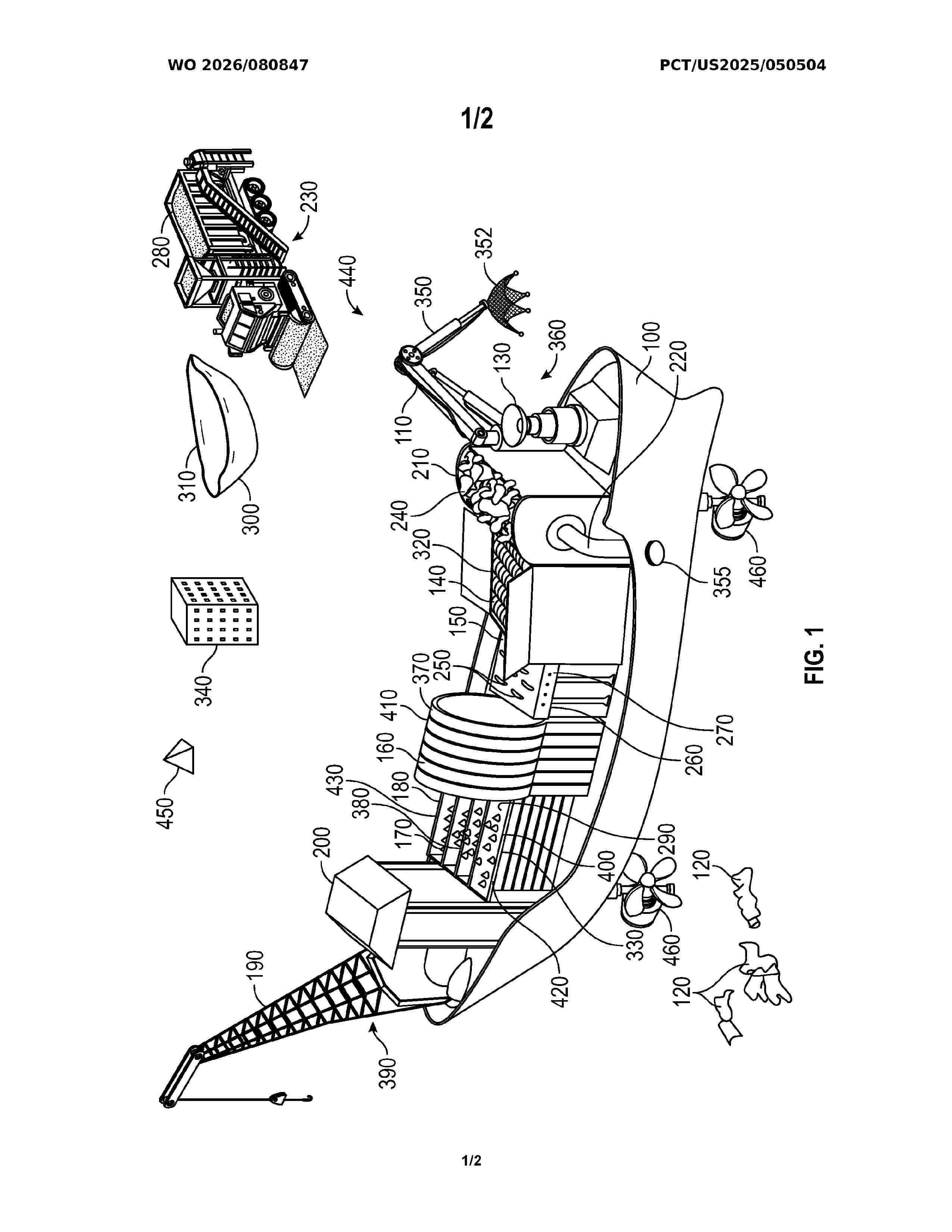
Resumen de: WO2026080847A1
A marine vessel designed for the collection, shredding, and pelletizing of oceanic plastic waste. The vessel uses renewable energy sources such as solar panels and wind turbines to power onboard systems, including Al-enhanced sensors that detect and target high-density areas of plastic debris. Once collected, the plastic is shredded and processed into uniform plastic pellets optimized for use in plastic asphalt production. The vessel also includes storage compartments for the pellets and a crane system for transferring containers filled with pellets to adjacent vessels or shore-based transport. This integrated system addresses inefficiencies in traditional ocean cleanup methods by enabling immediate onboard processing, reducing transportation needs, and repurposing plastic waste into a valuable industrial resource, while significantly minimizing environmental impact through sustainable energy use.
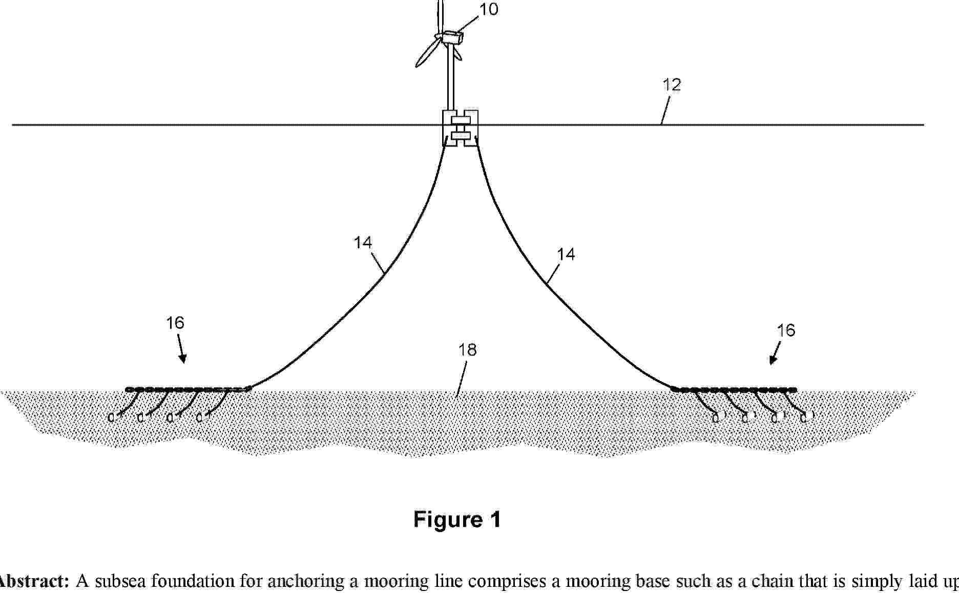
Resumen de: AU2024354596A1
A subsea foundation for anchoring a mooring line comprises a mooring base such as a chain that is simply laid upon the seabed in a straight, curved or looped configuration, hence extending across the seabed substantially parallel to the seabed. The mooring base is then anchored by one or more deadman anchors that are embedded in the seabed soil. For this purpose, one or more links extend through the soil to couple the mooring base to the or each deadman anchor. One or more mooring lines can then be coupled to the mooring base.
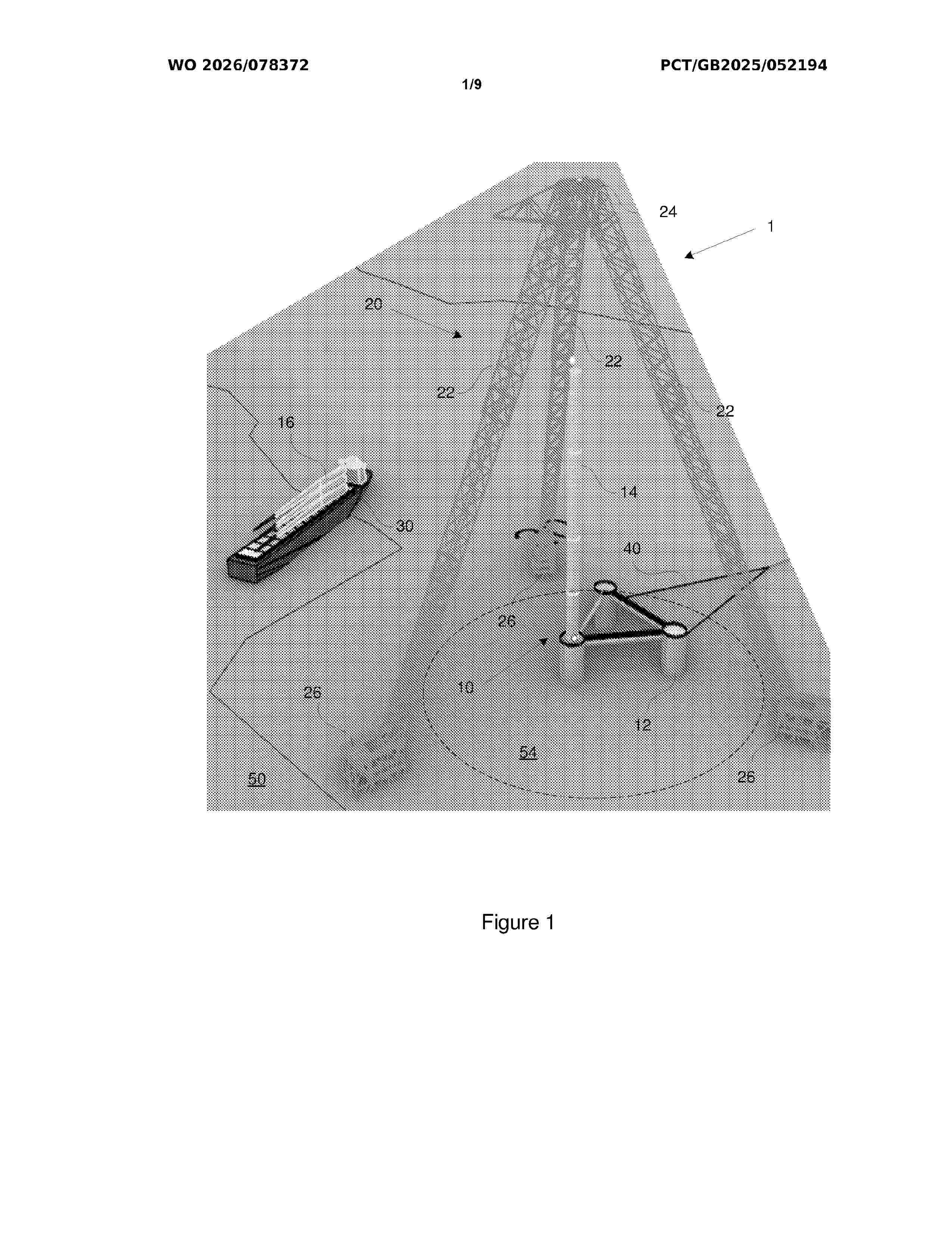
Resumen de: WO2026078372A1
An assembly system (100) for assembling an offshore structure (110), the assembly system comprising: a floating base (112) of the offshore structure (110); a lifting structure (120) configured to perform a landing operation, the landing operation comprising landing one or more components (114) of the offshore structure (110) onto the floating base (112); and a heave reduction system configured to selectively adjust a draft of the floating base (112) during the landing operation. A method (500) of assembling an offshore structure is also disclosed.
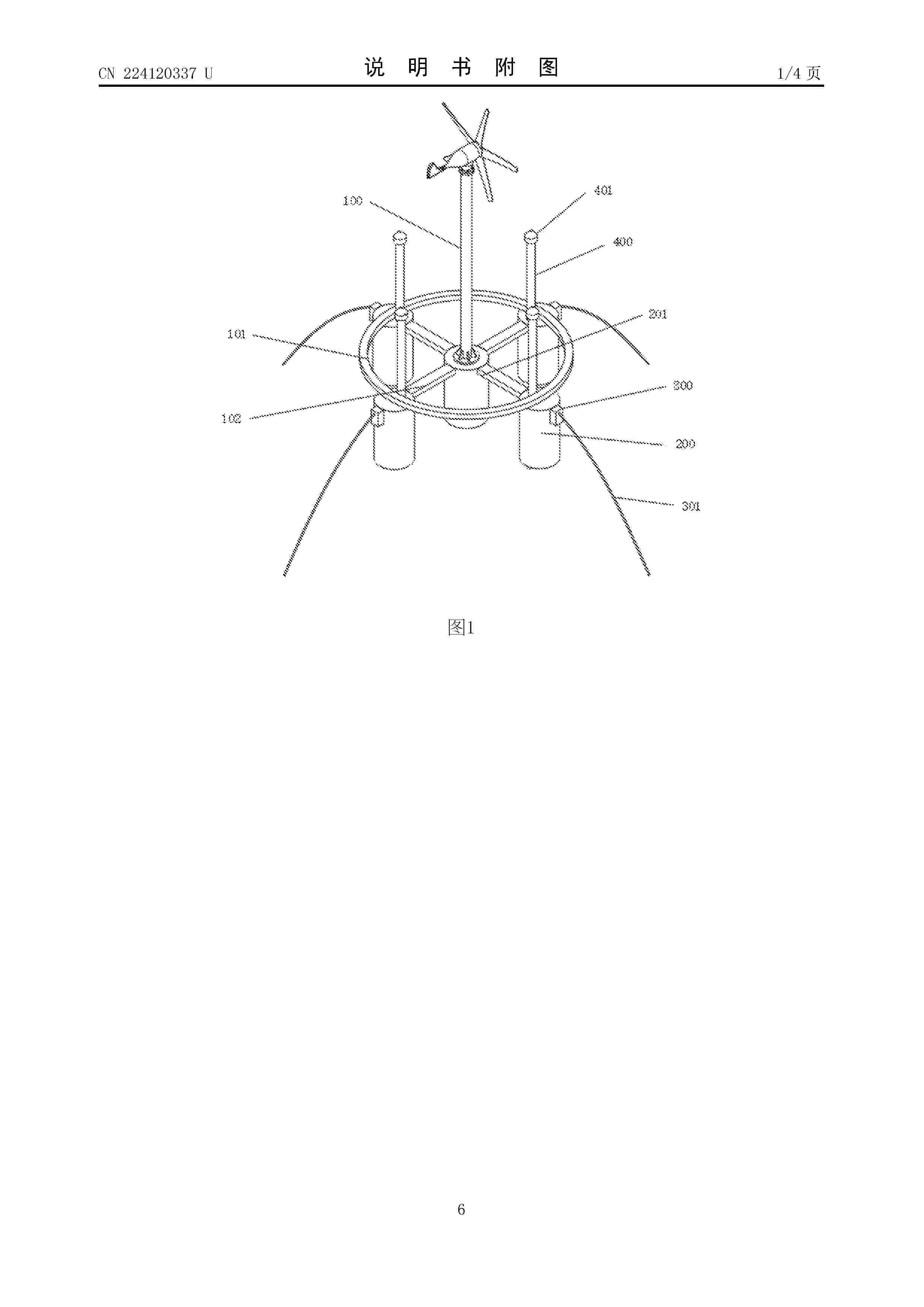
Resumen de: CN224120337U
The utility model discloses a floating fan gas-liquid linkage ballast balancing device with a bidirectional flow channel, which mainly comprises a gas-liquid linkage ballast cylinder and an annular mounting frame, and the gas-liquid linkage ballast cylinder comprises a central gas-liquid linkage ballast cylinder and an outer side gas-liquid linkage ballast cylinder; the gas-liquid linkage ballast cylinder is mainly composed of a cylinder, a plurality of sealing partition plates are arranged in the cylinder in the axial direction, the sealing partition plates divide a plurality of sealing cabins in the cylinder, a compression bin is formed between the bottommost sealing partition plate and the movable cover plate, and a compression air bag is installed in the compression bin. An electronic water inlet valve and an electronic drain valve are mounted on the inner wall of the sealed cabin; an air pipe is installed on the top face of the cylinder, and the output end of the air pump extends to each sealed cabin and the compression cabin through an air supply pipe. According to the device, gas and liquid can be dynamically adjusted through the sealed cabin, so that the position of the generator set on the sea surface is dynamically adjusted through mutual cooperation of the outer side gas-liquid linkage ballast cylinder and the center gas-liquid linkage ballast cylinder, impact of wind power and sea waves is effectively reduced, and the resistance of the device to the sea waves is r
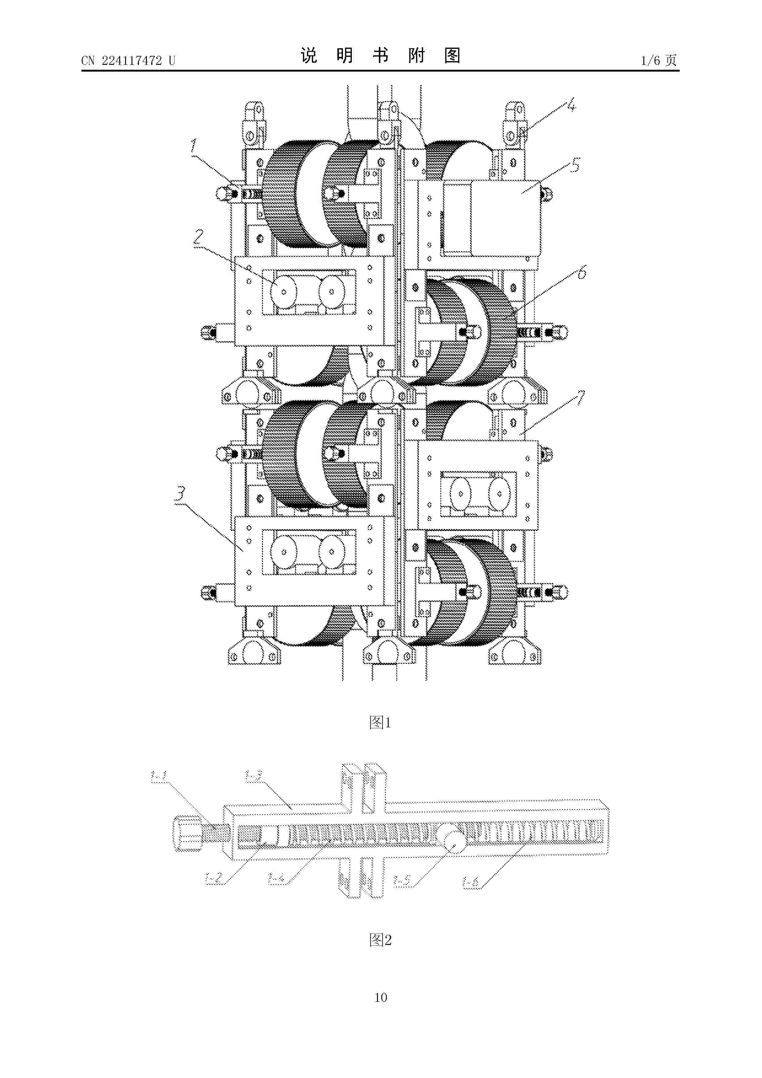
Resumen de: CN224117472U
The utility model provides a floating type wind power platform anchor chain clamping and stabilizing structure and a detection robot. The floating type wind power platform anchor chain clamping and stabilizing structure comprises a clamping and stabilizing device, a visual detection system, a buoyancy adjusting system, a hoisting hook, a control and operation system, a driving wheel and an external frame. The clamping stabilizing device, the buoyancy adjusting system, the hoisting hook, the control operation system and the driving wheel are all installed on the outer frame. The driving system is connected with a sliding block in the clamping and stabilizing device through a driving wheel, and it is ensured that the robot can stably move along the anchor chain. The control operation system is located in the control cabin and connected with the outer frame so as to achieve accurate control over the whole robot. The outer frame is not only used for fixing the robot to the anchor chain, but also optimizes the layout of all the components, so that the overall structure of the robot is compact and efficient, and the stability and reliability of the robot during task execution in a complex marine environment are guaranteed.
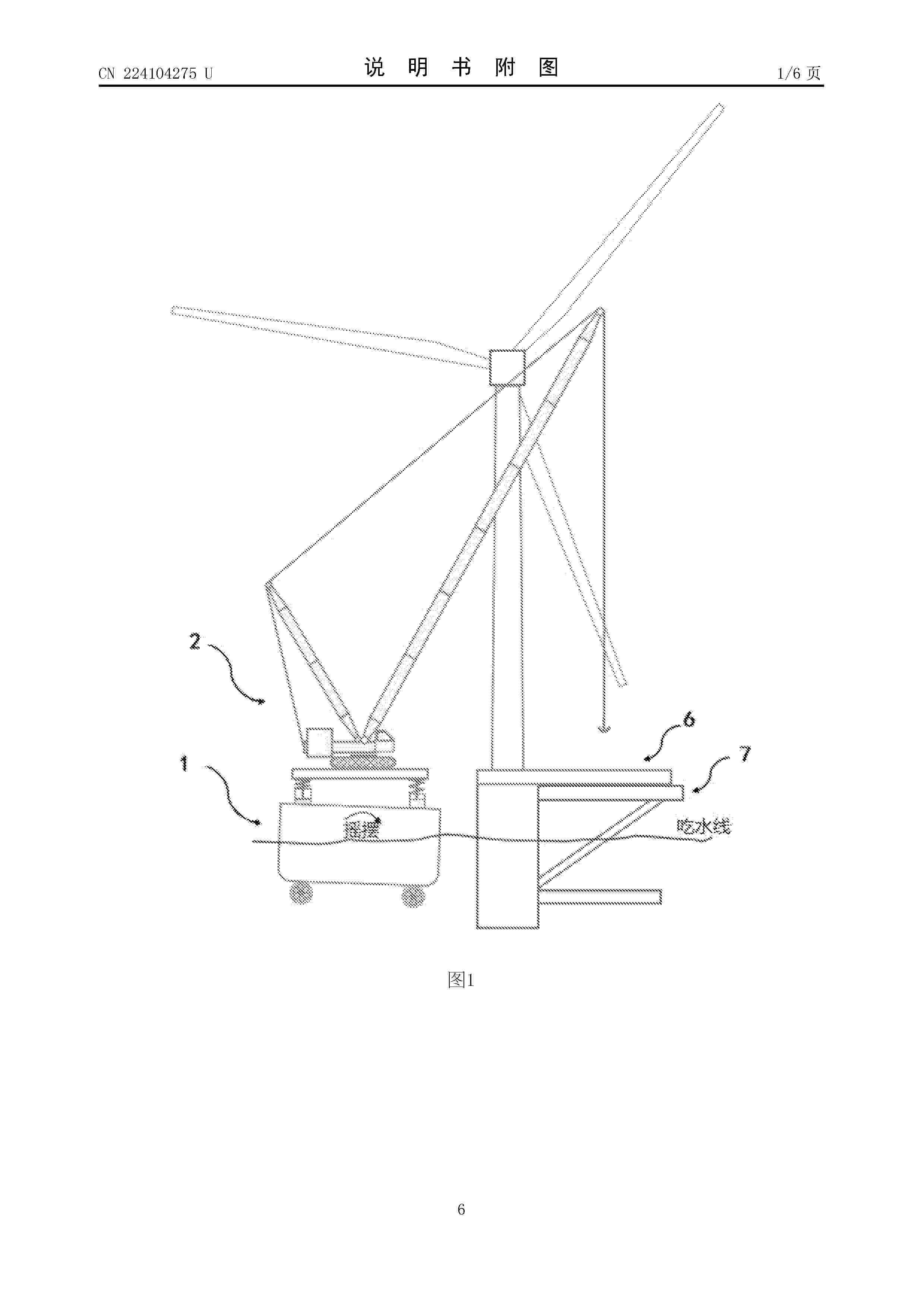
Resumen de: CN224104275U
The utility model relates to a device for carrying out field operation on an offshore floating platform. The device is characterized by comprising a transport ship, a floating platform, a mobile crane and a working platform, wherein the working platform can be used for movable operation of the mobile crane and can be installed on site; the working platform is arranged at the floating platform; and the transport ship is provided with transfer equipment, and the transfer equipment is used for moving the mobile crane to the working platform. The offshore floating platform can be suitable for a heavy-weight hoisting scene, existing equipment does not need to be greatly transformed, and offshore floating platform operation with the lowest operation and maintenance cost is achieved.
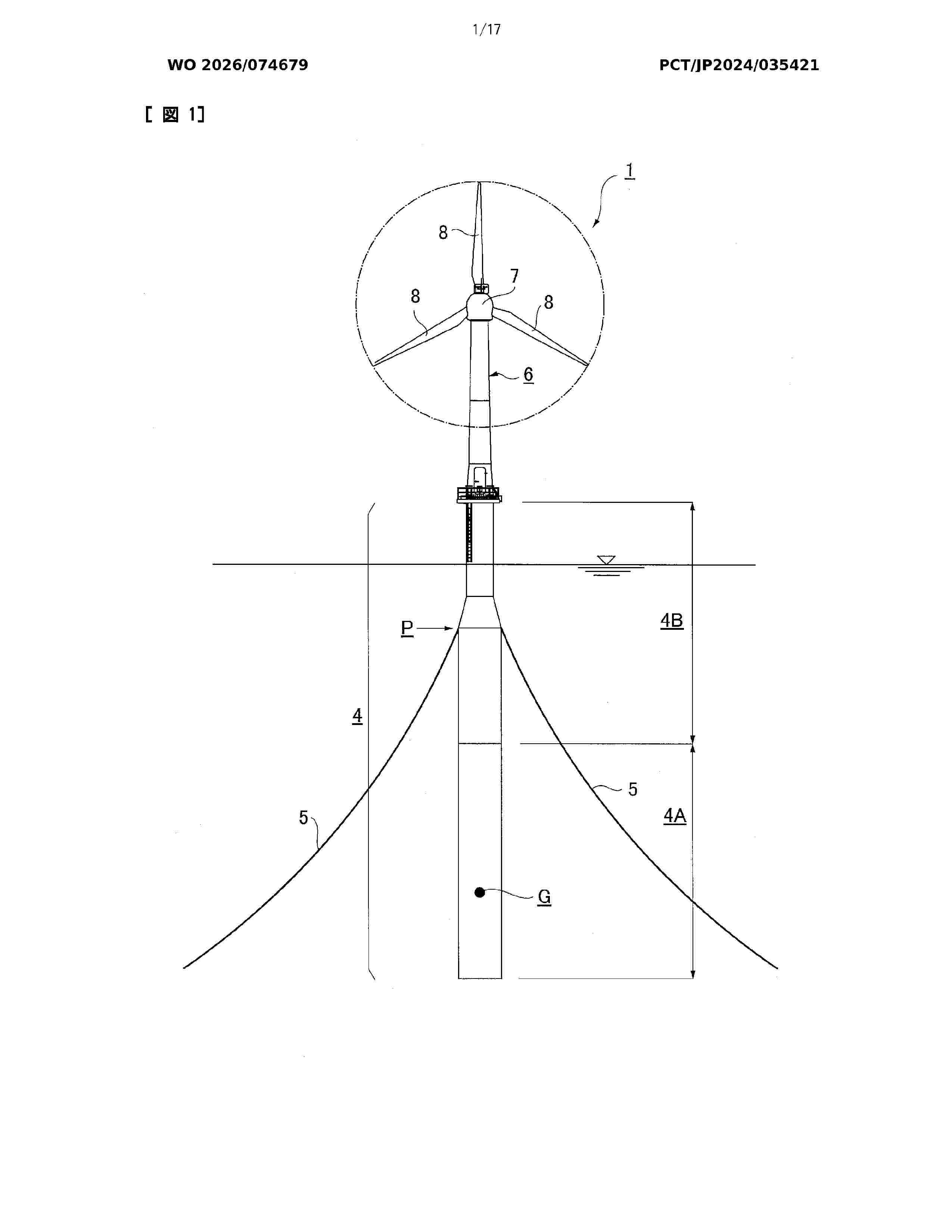
Resumen de: WO2026074679A1
Problem To enable efficient and low-cost construction of a spar-type floating body and to simultaneously solve problems such as thermal cracking and bending cracking of concrete. Solution In a spar-type floating body 4, the lower half side is a steel-concrete composite structure part 4A in which concrete C is cast in a predetermined thickness on the inner surface side of an outer shell steel member 10 covering the outer periphery. In the steel-concrete composite structure part 4A, reinforcing bars placed in the concrete C include polygonal first reinforcing bars 35 and second reinforcing bars 36 disposed alternately in a staggered manner at intervals in the longitudinal direction of the floating body, the first reinforcing bars 35 and the second reinforcing bars 36 being constituted by a large number of joint parts a welded to the outer shell steel member 10 over a predetermined length range and at predetermined intervals in the circumferential direction of the outer shell steel member 10, and chord parts b linearly connecting ends of adjacent joint parts a, a. At the center position of each chord part b of the first reinforcing bars 35 and the second reinforcing bars 36, a predetermined cover to the outer surface of the concrete is ensured.
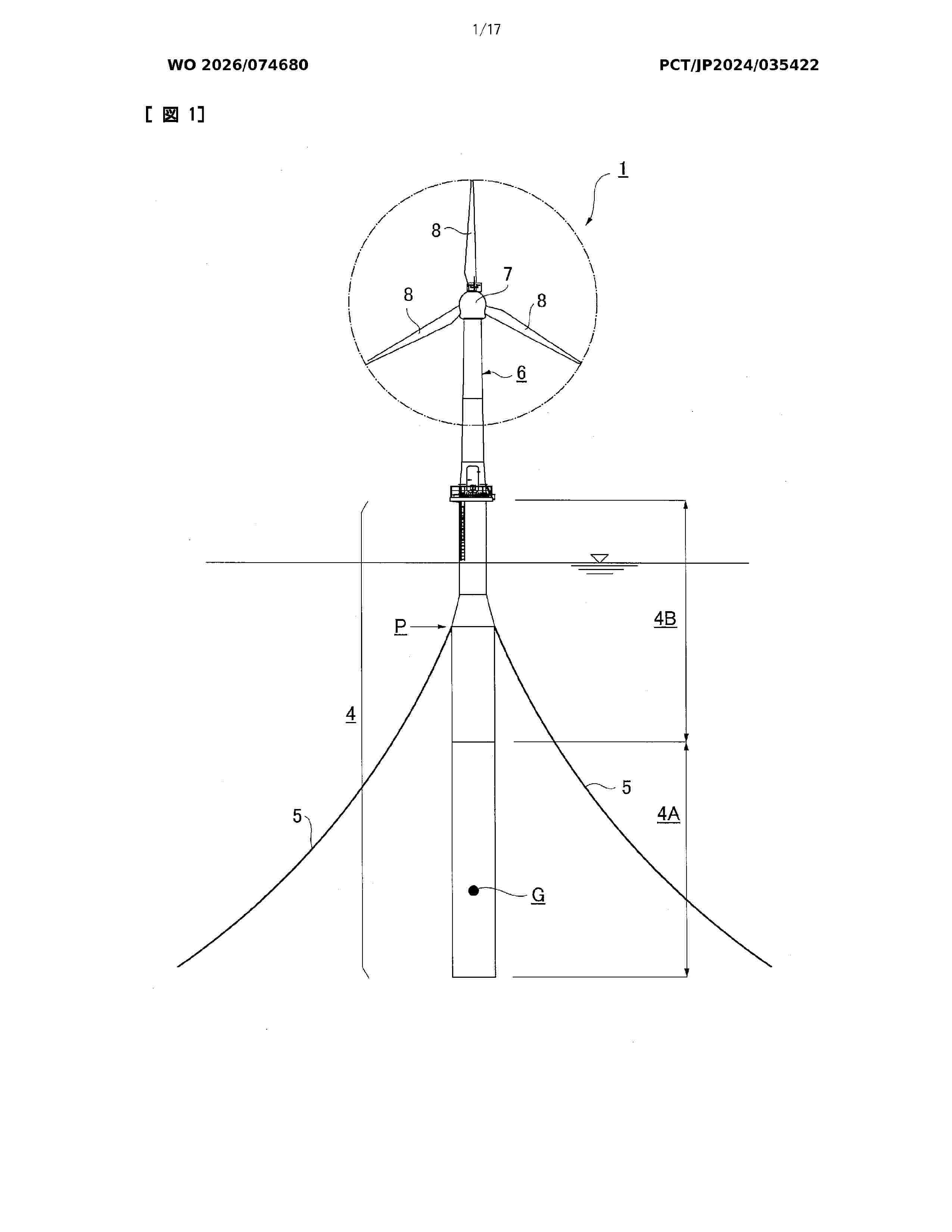
Resumen de: WO2026074680A1
Problem To efficiently construct a spar-type floating body at a low cost, and to simultaneously solve issues such as concrete temperature cracks and bending cracks. Solution A spar-type floating body 4 with the lower half thereof being imparted as a steel-concrete composite structure part 4A in which concrete C is cast to a prescribed thickness on the inner surface of an outer-shell steel member 10 that covers the outer periphery, and the upper half thereof having an outer-shell steel member 12 that covers the outer periphery and being imparted as a steel structure part 4B made entirely of steel members. In the steel-concrete composite structure part 4A, reinforcing bars embedded in the concrete C are formed by arranging assembly reinforcing bars 35 spaced at an interval P along the longitudinal direction of the floating body, each assembly reinforcement 35 comprising: an inner circumferential bar 36A arranged parallel to the outer-shell steel member 10 in a state of maintaining a prescribed cover K with respect to the concrete outer surface; and a zigzag-shaped truss bar 36B arranged so as to alternately connect, over each prescribed length, the inner circumferential bar 36A and the outer-shell steel member 10.
Resumen de: WO2024246109A1
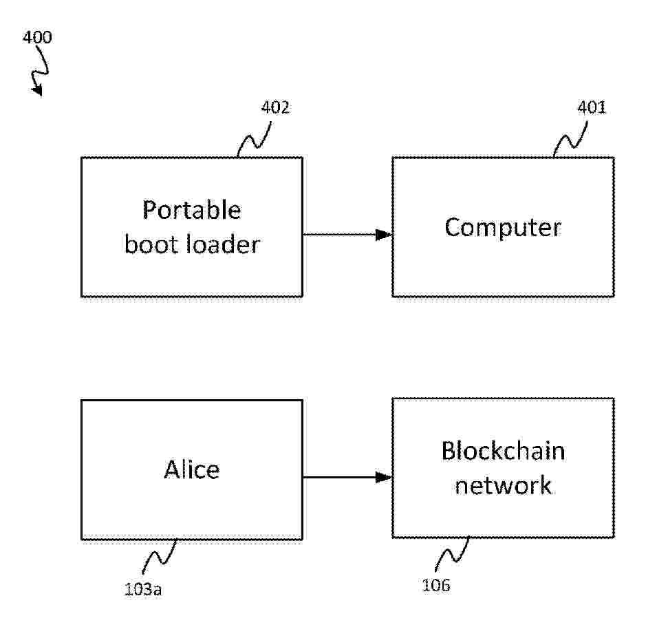
A computer-implemented method for booting a device using a portable boot loader device, wherein the portable boot loader device comprises a boot loader and operating system files, wherein a blockchain comprises a boot loader transaction, wherein the boot loader transaction comprises an output locked to a master public key, and wherein the boot loader transaction comprises a first signature signing the boot loader and a second signature signing the operating system files, and wherein the method comprises: obtaining the boot loader transaction; verifying the first signature using the master public key; verifying the second signature using the master public key; and loading the operating system files using the boot loader.
Resumen de: WO2024246109A1
A computer-implemented method for booting a device using a portable boot loader device, wherein the portable boot loader device comprises a boot loader and operating system files, wherein a blockchain comprises a boot loader transaction, wherein the boot loader transaction comprises an output locked to a master public key, and wherein the boot loader transaction comprises a first signature signing the boot loader and a second signature signing the operating system files, and wherein the method comprises: obtaining the boot loader transaction; verifying the first signature using the master public key; verifying the second signature using the master public key; and loading the operating system files using the boot loader.
Resumen de: EP4722453A1
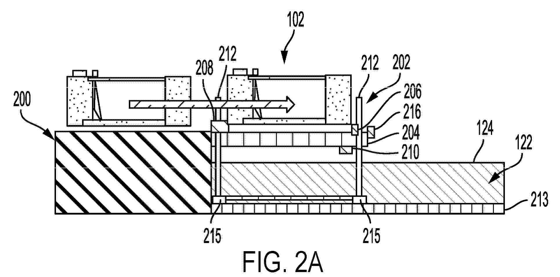
A relocatable quay includes a deck that is relocatable in a body of water adjacent a stationary quay. The deck is positioned at the stationary quay to receive a floating unit. The relocatable quay also includes an elevator system positionable to raise and lower the deck to receive the floating unit from the stationary quay and to deploy the floating unit into the body of water.
Resumen de: WO2024246109A1
A computer-implemented method for booting a device using a portable boot loader device, wherein the portable boot loader device comprises a boot loader and operating system files, wherein a blockchain comprises a boot loader transaction, wherein the boot loader transaction comprises an output locked to a master public key, and wherein the boot loader transaction comprises a first signature signing the boot loader and a second signature signing the operating system files, and wherein the method comprises: obtaining the boot loader transaction; verifying the first signature using the master public key; verifying the second signature using the master public key; and loading the operating system files using the boot loader.
Resumen de: EP4722100A1
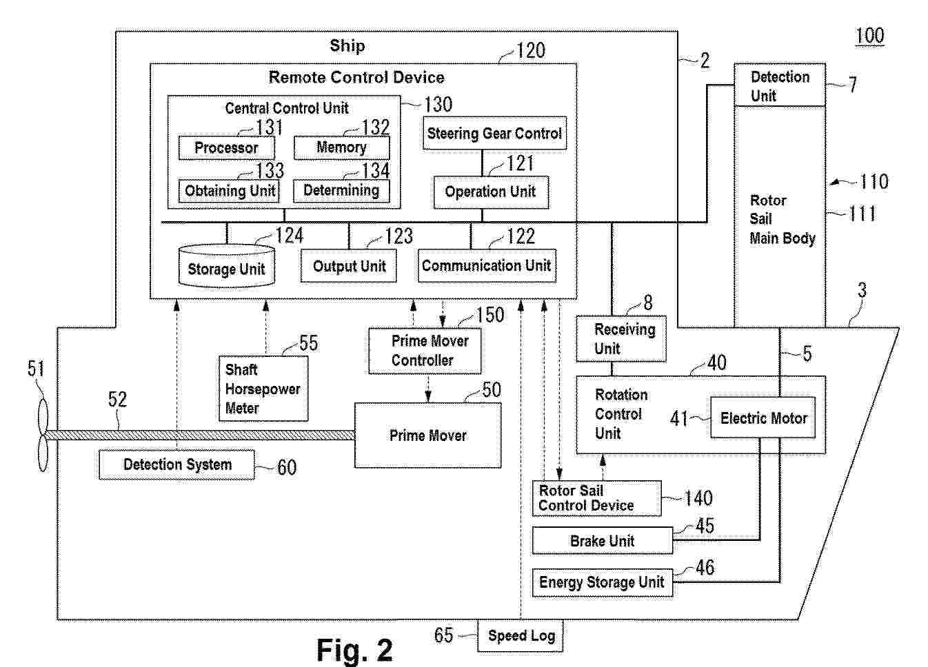
A rotor sail system includes: a vertical support post extending in a vertical direction from a hull; a blade connected to a shaft, the blade being rotatable about the shaft, the shaft extending in a predetermined direction with reference to the vertical support post; a detection unit detecting a wind direction and a wind speed in a navigation area of a ship; a receiving unit receiving a thrust command to specify a thrust of the ship; and a rotation control unit capable of controlling a rotational speed of the blade about the shaft. The rotation control unit controls the rotational speed of the blade about the shaft based on the received thrust command and a detection result of the wind direction and the wind speed detected when the thrust command is received.
Resumen de: EP4722095A1
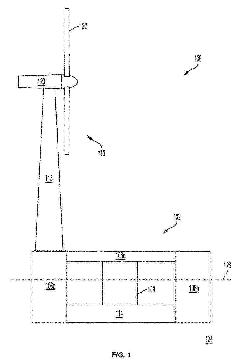
A floating platform system can be provided to facilitate mounting of and for supporting a structure on a floating platform. For example, the floating platform system can include the floating platform. The floating platform system can also include a ballast receiving volume inside the floating platform for receiving a ballasting liquid. The floating platform system can further include a mounting surface on the floating platform for mounting a structure. Additionally, the floating platform can include a downwardly-oriented stabbing guide.
Nº publicación: CN224075736U 03/04/2026
Solicitante:
SPIC JIANGSU ELECTRIC POWER CO LTD
SPIC JIANGSU OFFSHORE WIND POWER GENERATION CO LTD
\u56FD\u5BB6\u7535\u6295\u96C6\u56E2\u6C5F\u82CF\u7535\u529B\u6709\u9650\u516C\u53F8
\u56FD\u5BB6\u7535\u6295\u96C6\u56E2\u6C5F\u82CF\u6D77\u4E0A\u98CE\u529B\u53D1\u7535\u6709\u9650\u516C\u53F8
Resumen de: CN224075736U
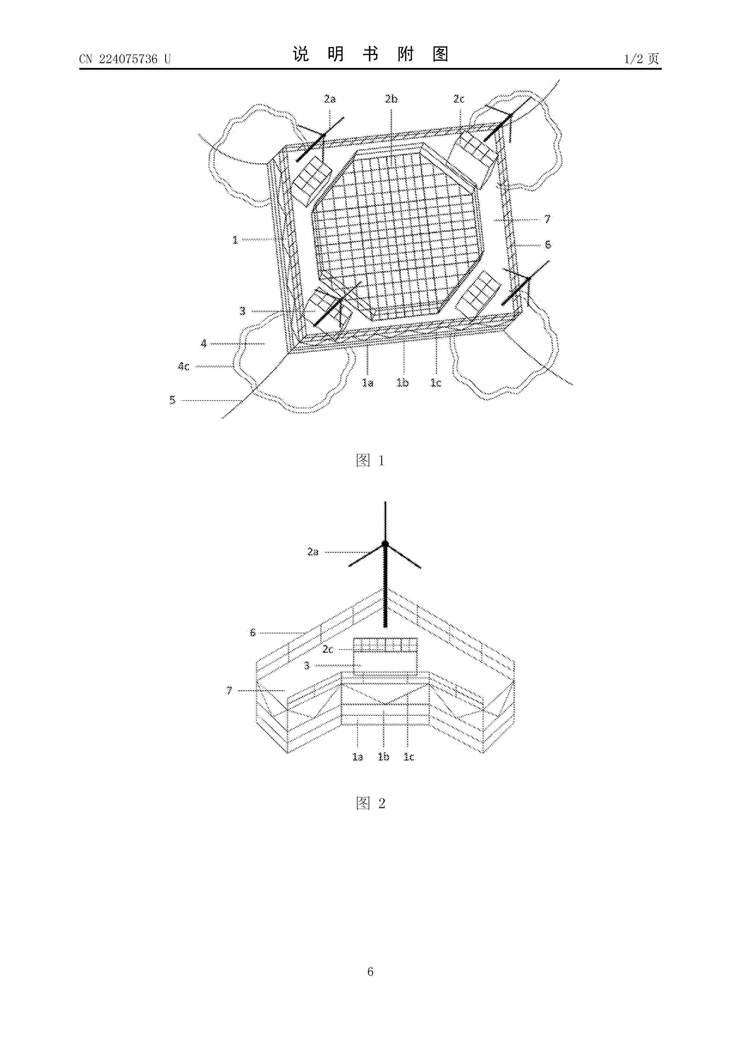
The utility model discloses an offshore wind power system, photovoltaic system and aquaculture system integrated floating platform, and belongs to the technical field of marine resource comprehensive application. The platform comprises a floating body, a power generation system, a sunshade, a breeding system and a mooring system. The power generation system comprises draught fans installed at the four corners of the floating body, a photovoltaic module installed in the middle of the floating body and a solar panel arranged on the sunshade, and the breeding system mainly comprises net hauler equipment in the sunshade, special equipment for the aquaculture industry and a netting arranged below the sunshade. After being assembled into a whole, the parts are transported to a designated sea area through a ship and connected with a mooring system to form the wind, light and fish integrated deep sea floating platform. The platform can well solve the problem of land use conflicts when an offshore wind power system, an offshore photovoltaic system and an aquaculture system are independently developed and built, the arrangement interval space and the lower space of wind turbine generators in an offshore wind power plant are reasonably utilized, the resource and energy utilization rate is increased, and therefore the purposes of reducing cost and improving efficiency are achieved.
 BOPI
BOPI
 Sede Electrónica