Si deseas distinguir tus productos, servicios o ambos de los de otra empresa, es posible que necesites una marca o nombre comercial. Descubre qué son, en qué consiste su procedimiento de registro y qué implica.

Información sobre los plazos de presentación de solicitudes de transformación de marcas de la Unión Europea en marca nacional española. Más información


Si tienes un nuevo dispositivo, producto o procedimiento que resuelva un problema técnico o tenga una ventaja práctica, existen distintas formas de protegerlo en España y en otros países. Descubre cómo hacerlo.

¿Tu innovación reside en la estética, la ornamentación o la apariencia de tu producto? Protégela mediante un diseño industrial. Descubre qué derechos confiere el registro y cómo realizar la tramitación.

Las indicaciones geográficas protegen el nombre de un producto originario de una zona geográfica, a la cual le debe una determinada calidad, reputación u otra característica. Descubre qué son, en qué consiste su procedimiento de registro y qué beneficios conceden.

Las patentes publicadas en todo el mundo son una valiosa fuente de información científica, técnica y comercial.

Si eres emprendedor/a o una empresa y quieres potenciar y mejorar la rentabilidad de tu negocio protegiendo de forma adecuada los activos intangibles de tu organización, en este espacio encontrarás lo necesario.


 1603
resultados
1603
resultados
 Última actualización
24/06/2026 [07:18:00]
Última actualización
24/06/2026 [07:18:00]


 Resultados 150 a 175 de 1603

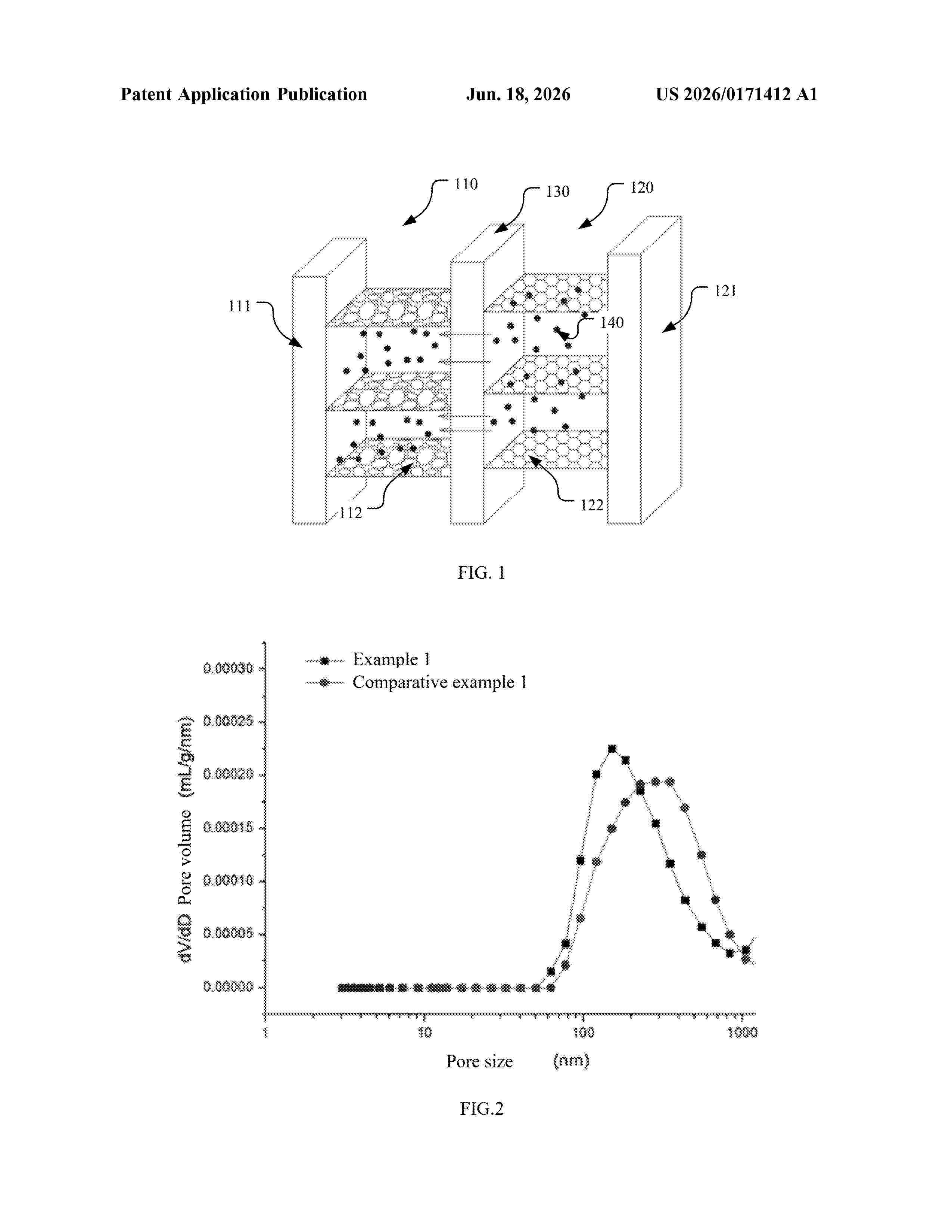
Resumen de: US20260171412A1
An anode material comprising: a carbon material having pores therein, wherein a total pore volume of pores with a pore size of 3 nm or more and 1,000 nm or less, measured by mercury intrusion porosimetry is V1, and 0

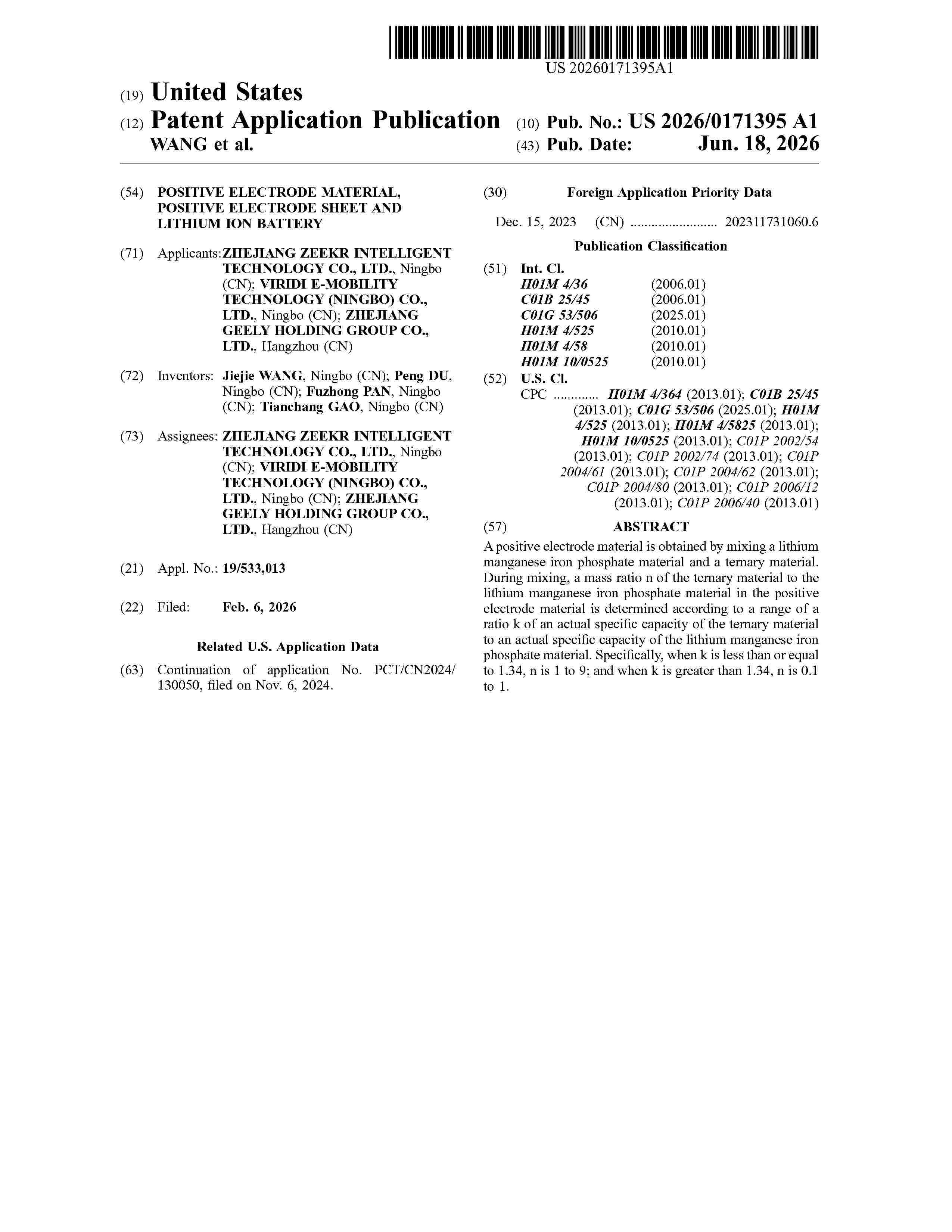
Resumen de: US20260171395A1
A positive electrode material is obtained by mixing a lithium manganese iron phosphate material and a ternary material. During mixing, a mass ratio n of the ternary material to the lithium manganese iron phosphate material in the positive electrode material is determined according to a range of a ratio k of an actual specific capacity of the ternary material to an actual specific capacity of the lithium manganese iron phosphate material. Specifically, when k is less than or equal to 1.34, n is 1 to 9; and when k is greater than 1.34, n is 0.1 to 1.
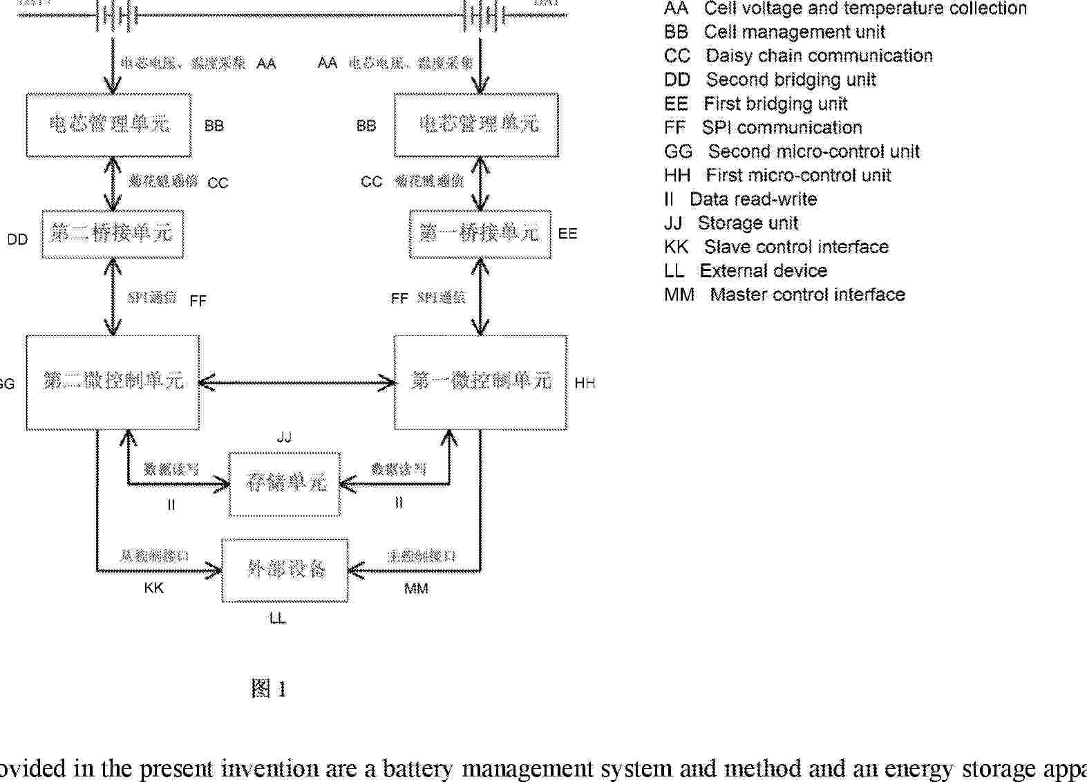
Resumen de: AU2025214887A1
Provided in the present invention are a battery management system and method and an energy storage apparatus. The battery management system comprises micro-control units and a collection unit, wherein each micro-control unit is used for receiving and/or sending a control signal, the collection unit is used for collecting cell parameters, two ends of the collection unit are connected to the micro-control units, the collection unit comprises at least one cell management unit, each cell management unit is provided with an analog front end, each analog front end is used for connecting to one cell for collection of the cell parameters, there are two micro-control units and two cell management units, each cell management unit is connected to one micro-control unit, and the two micro-control units share parameter signals and the control signals. The battery management system of the present invention can manage each cell, so as to allow for more balanced workload of each component, thus reducing the risk of slave control failures; and the battery management system can fully use the two micro-control units, so as to make system operation safer and more reliable.
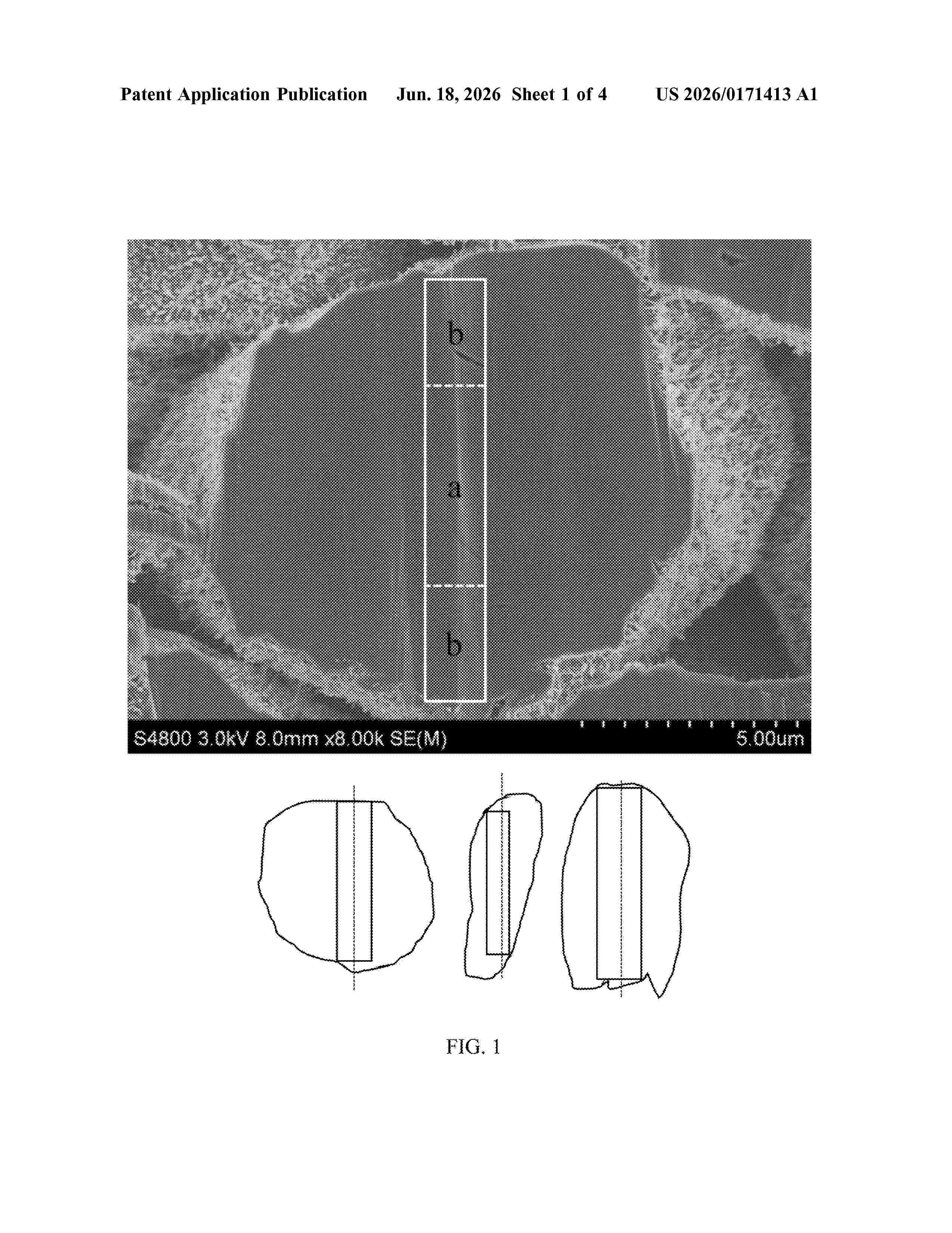
Resumen de: US20260171413A1
0000 An anode material includes a core and a coating layer. The coating layer is located on a surface of the core, the core includes natural graphite and first amorphous carbon filled in pores of the natural graphite, and the coating layer includes second amorphous carbon. A Raman spectrum of the anode material has a D peak and a G peak, and an intensity ratio of the D peak to the G peak is I
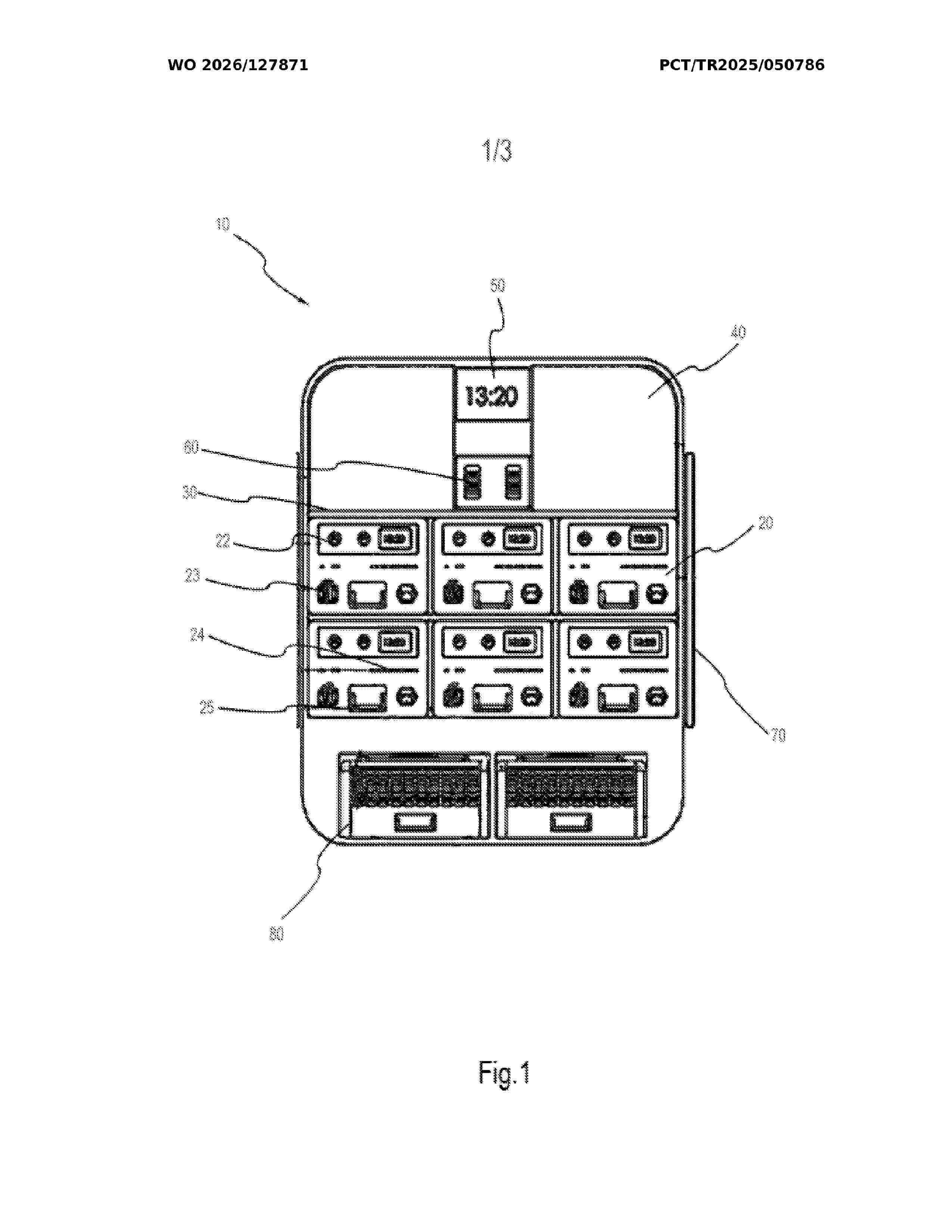
Resumen de: WO2026127871A1
The invention relates to a modular battery storage cabinet (10) comprising at least one central inverter (40) that enables electrical energy to be stored efficiently and makes the stored electrical energy suitable for domestic or industrial use, at least one digital display (50) that visually presents the energy status and system performance to the user, at least one battery (20) as a modular unit used for storing energy, and at least one shelf (30) in which the battery (20) is positioned. Accordingly, its novelty is that it comprises at least one solar panel (70) connected to the adjacent side of the modular battery storage cabinet (10) to ensure maximum efficiency from solar energy and minimize energy consumption, at least one portable air conditioning module (80) with a modular structure used to control and optimize the temperature levels of the system, at least one modular inverter (21) that enables the battery (20) to independently supply energy, and at least one battery management system (28) that allows the battery (20) to be safely charged and discharged.
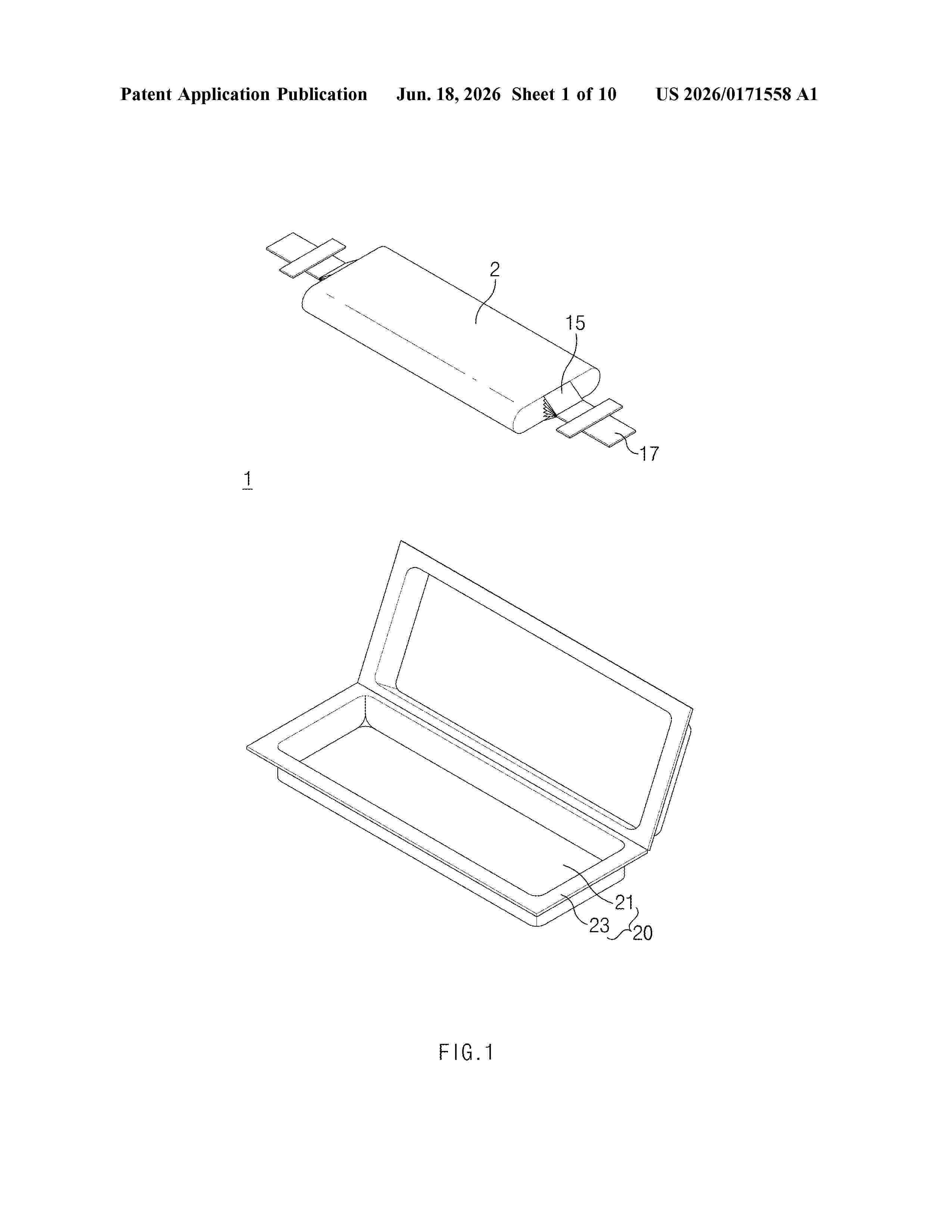
Resumen de: US20260171558A1
0000 A pouch-type secondary battery includes: a first pouch having a first cup portion recessed in a first direction forming a first inner space, and a first edge portion extending from the first cup portion in a horizontal direction perpendicular to the first direction and surrounding a portion of the first cup portion; and a second pouch disposed to face the first pouch and including a second cup portion recessed in a direction opposite to the first direction forming a second inner space cooperating with the first inner space, and a second edge portion extending from the second cup portion in the horizontal direction to surround at a portion of the second cup portion and coupled to the first edge portion. The second inner space includes: an overlapping space overlapping the first inner space in the first direction, and an additional space in the horizontal direction and not overlapping the first inner space.
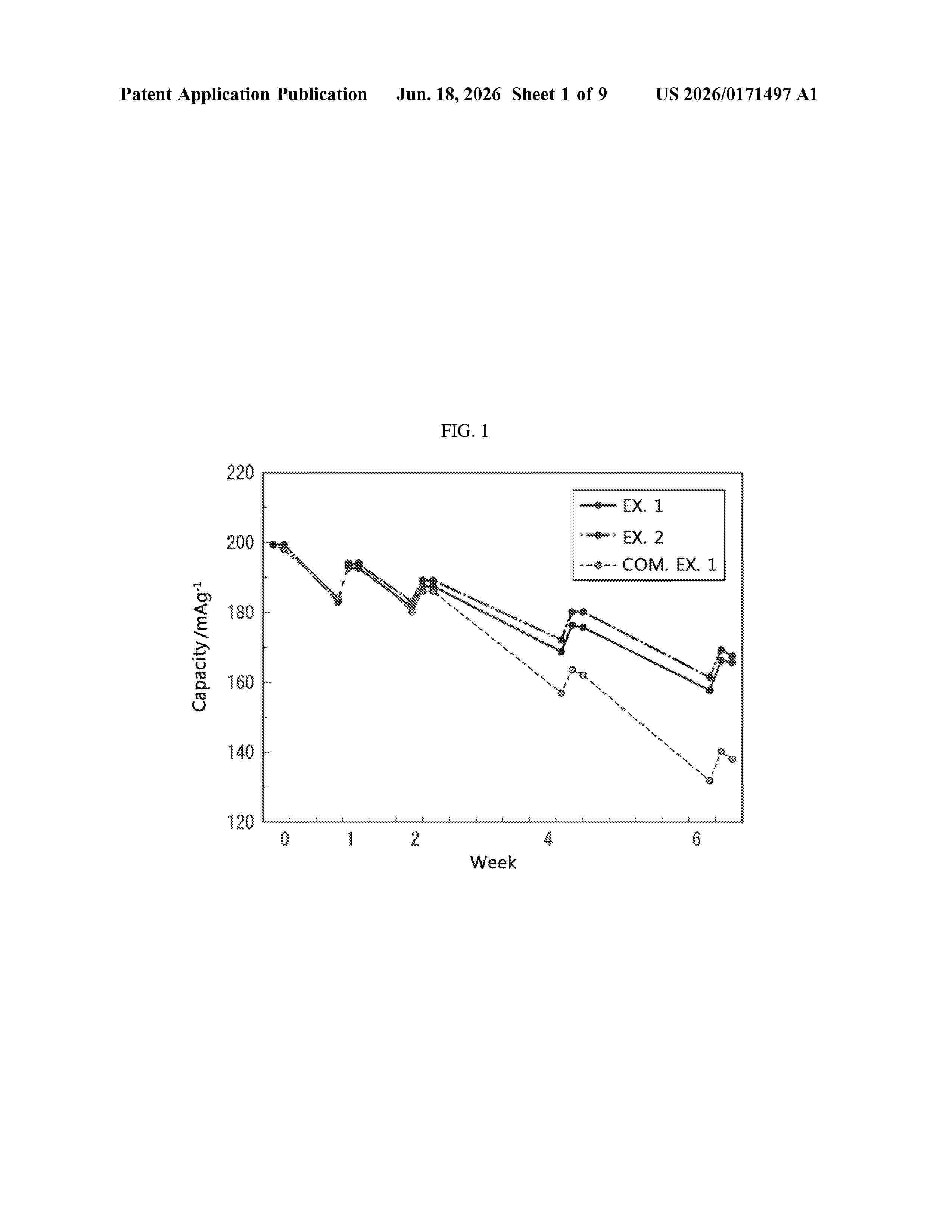
Resumen de: US20260171497A1
A non-aqueous electrolyte solution may reduces acid and/or moisture to decrease gas generation under high temperature conditions in order to suppress degradation in battery characteristics. An acid or moisture reducing agent for the non-aqueous electrolyte solution includes a diisocyanate compound represented by Formula (1), Formula (2), or Formula (3), wherein the non-aqueous electrolyte solution includes a fluorine atom-containing cyclic carbonate:
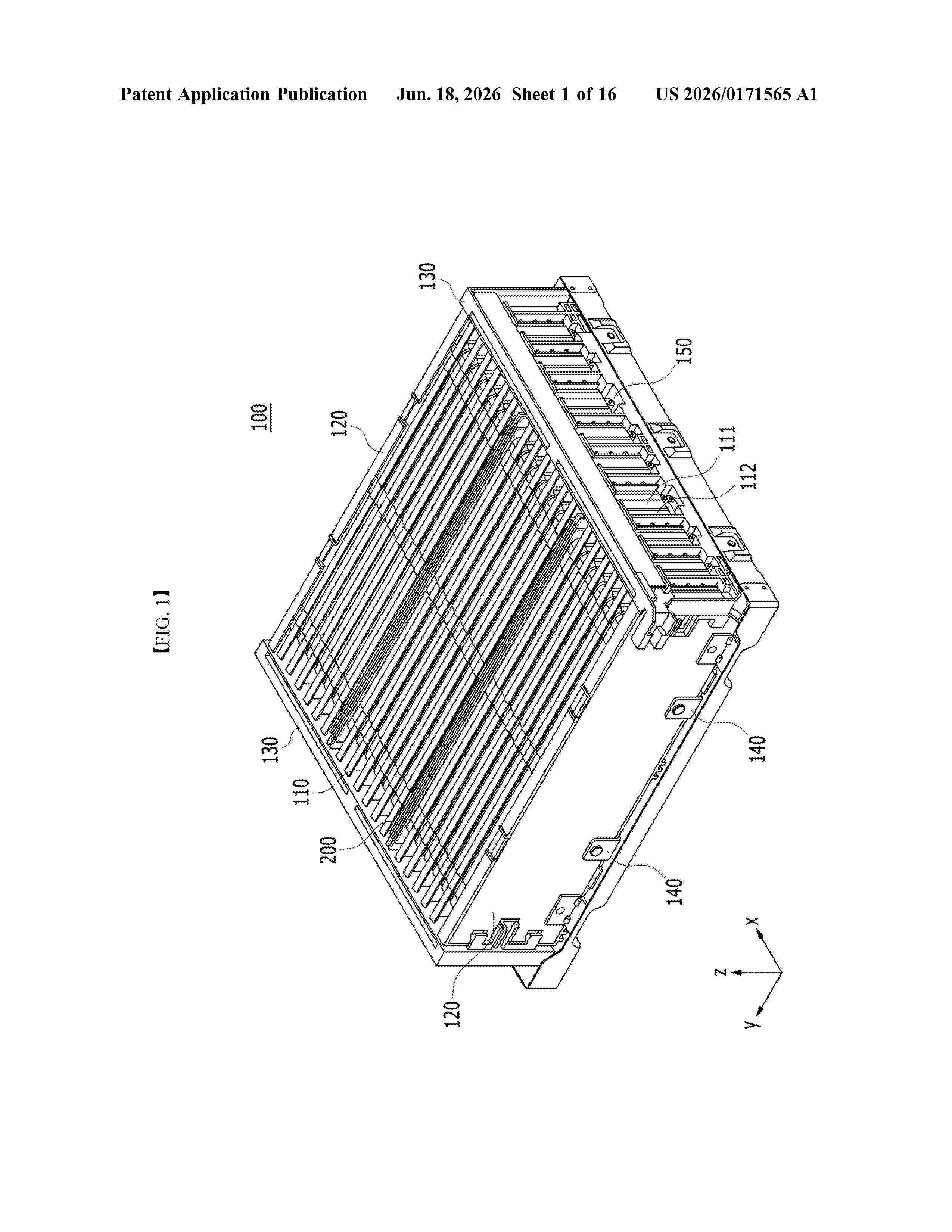
Resumen de: US20260171565A1
A cell module assembly in an example includes a battery cell stack in which a plurality of battery cells are stacked; and a blocking member disposed between at least one of the plurality of battery cells and at least another one of the plurality of battery cells. The blocking member includes a support plate, and the support plate includes a main body and a spacer coupled to the main body. The spacer has a higher melting point than the main body so as to maintain a shape and structure of the spacer during a battery cell thermal event.
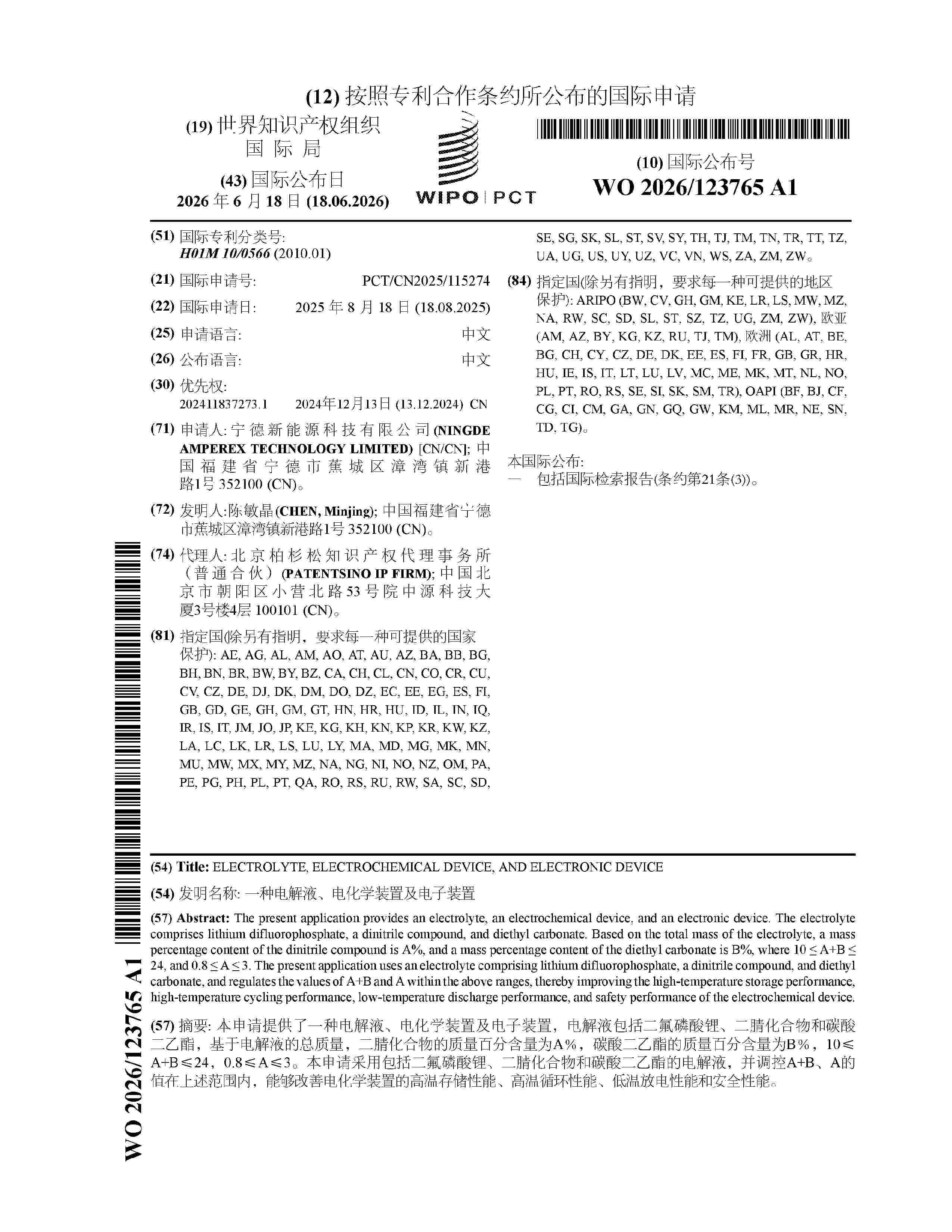
Resumen de: WO2026123765A1
The present application provides an electrolyte, an electrochemical device, and an electronic device. The electrolyte comprises lithium difluorophosphate, a dinitrile compound, and diethyl carbonate. Based on the total mass of the electrolyte, a mass percentage content of the dinitrile compound is A%, and a mass percentage content of the diethyl carbonate is B%, where 10 ≤ A+B ≤ 24, and 0.8 ≤ A ≤ 3. The present application uses an electrolyte comprising lithium difluorophosphate, a dinitrile compound, and diethyl carbonate, and regulates the values of A+B and A within the above ranges, thereby improving the high-temperature storage performance, high-temperature cycling performance, low-temperature discharge performance, and safety performance of the electrochemical device.
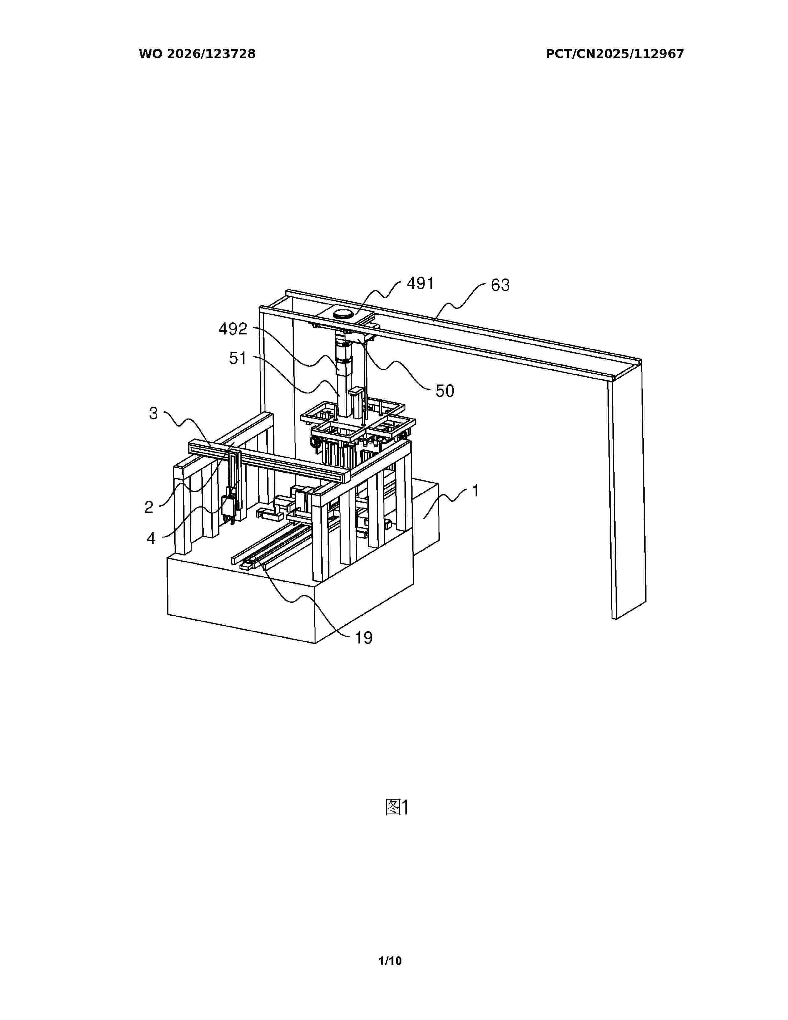
Resumen de: WO2026123728A1
The present invention relates to the technical field of battery pack production, and disclosed is an automatic stacking mounting lifting device for a battery pack, comprising a frame body, a feeding apparatus, a stacking apparatus, and a transfer apparatus. The feeding apparatus comprises a feeding moving mechanism and a feeding clamping mechanism. The stacking apparatus comprises a stacking moving mechanism, a first carrier frame, second carrier frames, and a stacking positioning mechanism, each second carrier frame is provided with an x-axis positioning assembly, and the x-axis positioning assembly comprises a fixed plate, a first driving member, and a first positioning plate. The stacking positioning mechanism comprises second positioning plates and second driving members, and the second driving members are used for driving the second positioning plates to move close to or away from the second carrier frames. The transfer apparatus comprises a transfer moving mechanism and a transfer clamping mechanism. The present application enables battery cells to be less prone to positional deviation during stacking, thereby ensuring the assembly stacking quality of the battery cells.
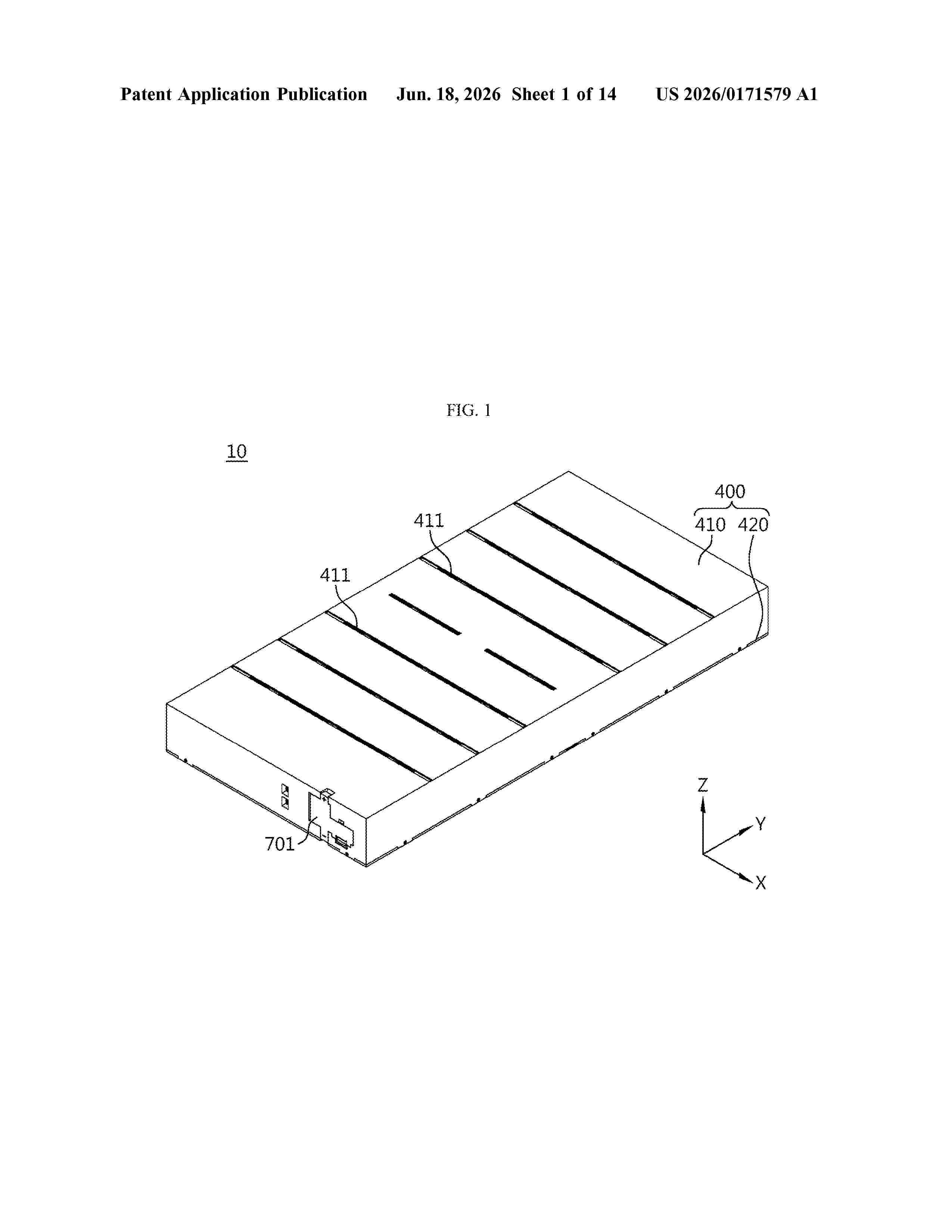
Resumen de: US20260171579A1
0000 Discussed is a battery back that may include at least one cell assembly and a pack case configured to accommodate the at least one cell assembly. The at least one cell assembly may include: two or more cell stacks including battery cells that are stacked; a cell pressurization unit disposed at outermost positions on opposite sides of each cell stack in a stacking direction of the battery cells and configured to provide pressing force to each cell stack; and a bus-bar frame assembly disposed at a front and a rear of the two or more cell stacks in a direction intersecting the stacking direction of the battery cells and configured to electrically connect the battery cells and integrally support the two or more cell stacks and the cell pressurization unit.
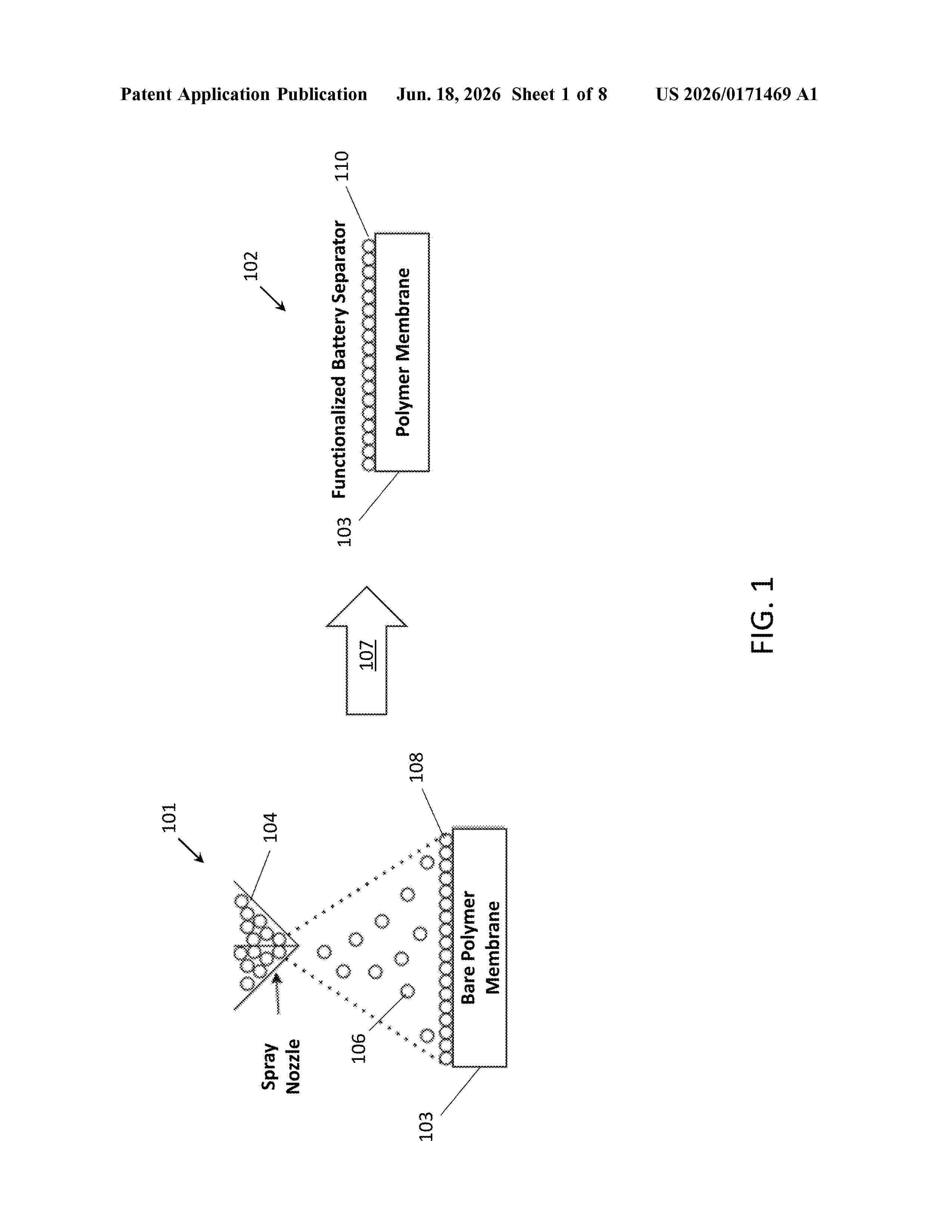
Resumen de: US20260171469A1
A functional battery separator including a bare separator component with a lithiophilic coating is disclosed. In particular, the lithiophilic coating is formed on a surface of the bare separator component, wherein the lithiophilic coating includes particles of an applied functional lithiophilic solution.
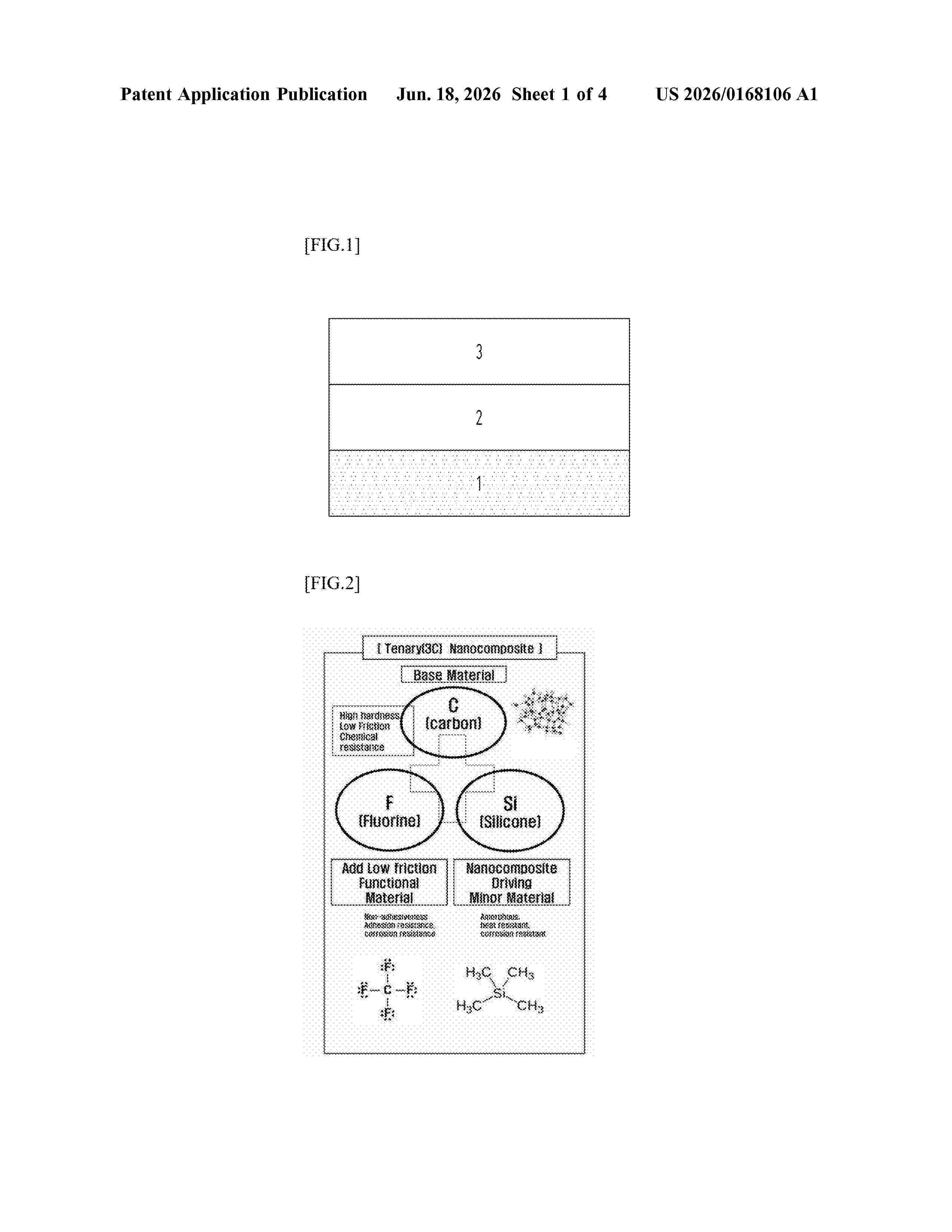
Resumen de: US20260168106A1
It is an object to provide a coating material having heat resistance, adhesion resistance, durability, chemical resistance, low friction, and releaseability applied to a base material, and to provide a manufacturing method and manufacturing system for such a coating material. A ternary nanocoposite coating material comprising C—F—H or C—F—Si applied to a base material is disclosed.
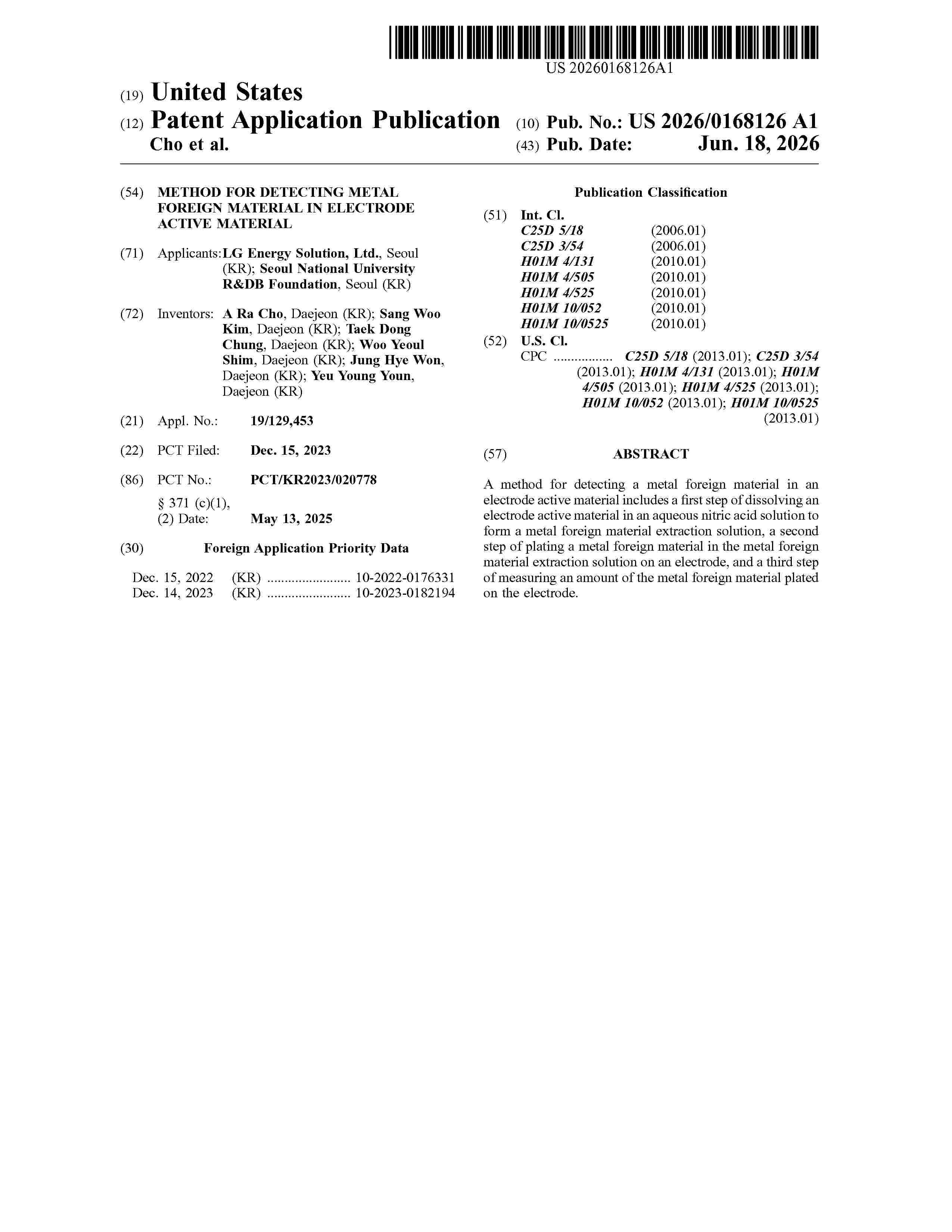
Resumen de: US20260168126A1
A method for detecting a metal foreign material in an electrode active material includes a first step of dissolving an electrode active material in an aqueous nitric acid solution to form a metal foreign material extraction solution, a second step of plating a metal foreign material in the metal foreign material extraction solution on an electrode, and a third step of measuring an amount of the metal foreign material plated on the electrode.
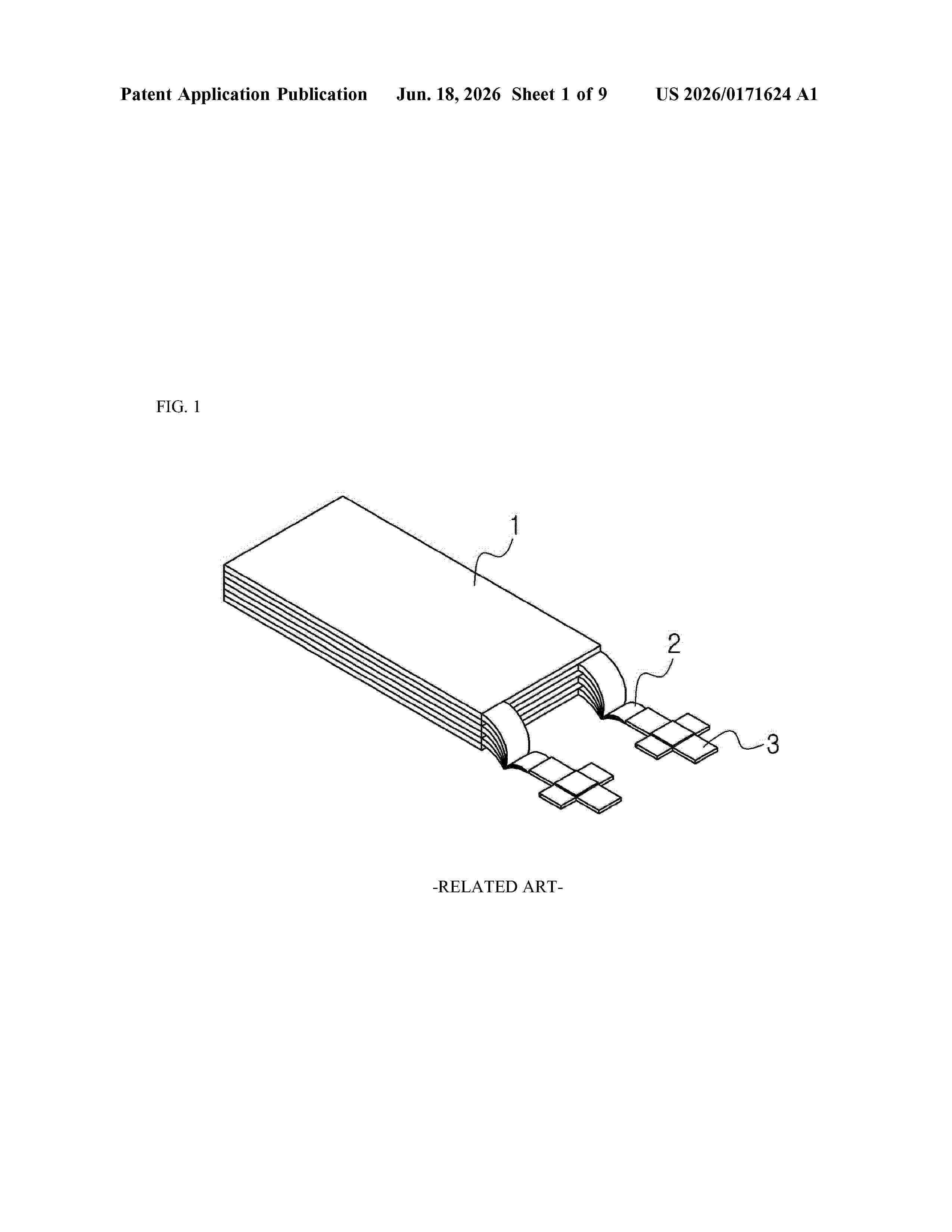
Resumen de: US20260171624A1
0000 A lead tab for bonding an electrode tab, a method for bonding the lead tab to the electrode tab, and a lithium secondary battery including a structure in which the lead tab is bonded to the electrode tab, which can prevent deformation of a lithium negative electrode tab by exposure while improving the physical strength and safety of the bonding area, are disclosed. The lead tab for bonding to the electrode tab includes: a first metal lead; and a second metal lead, wherein one end of the second metal lead is in contact with the first metal lead, and capping the electrode tab to form a bonding area.
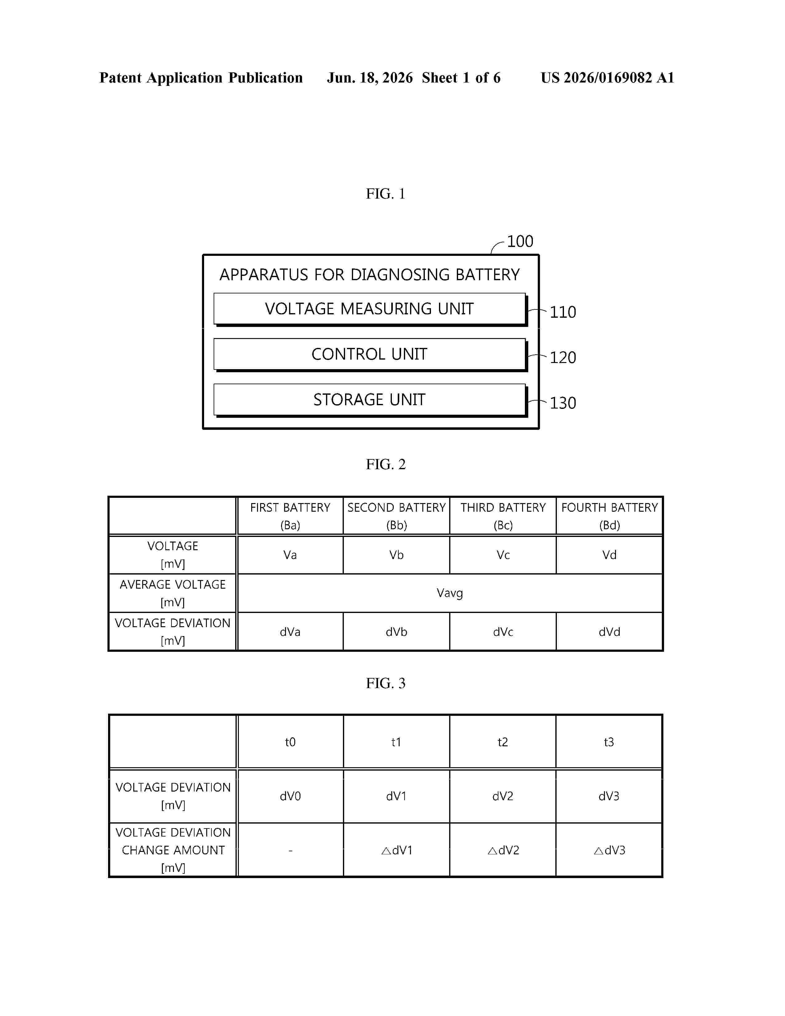
Resumen de: US20260169082A1
0000 An apparatus for diagnosing a battery includes a voltage measuring unit configured to measure voltages of a plurality of batteries, and a control unit configured to calculate a voltage deviation of the plurality of batteries, calculate a voltage deviation change amount of each of the plurality of batteries, and diagnose a state of each of the plurality of batteries based on the voltage deviation change amount and a calculation period of the voltage deviation change amount.
Resumen de: AU2024419101A1
The present invention relates to the technical field of safety protection of commercial lithium-ion batteries, and in particular, to a battery thermal protection system and application thereof. The battery thermal protection system consists of multifunctional coatings coated on a surface of an aluminum housing of each cell of a commercial lithium-ion battery and a fluid between cells in a module. The multifunctional coatings are one or a combination of an organic coating, an inorganic coating, and an organic-inorganic hybrid coating, and the number of layers of the multifunctional coatings is 1-10. Damage of thermal runaway of a single cell to adjacent cells and a whole battery set can be greatly reduced, and propagation of the thermal runaway is blocked.
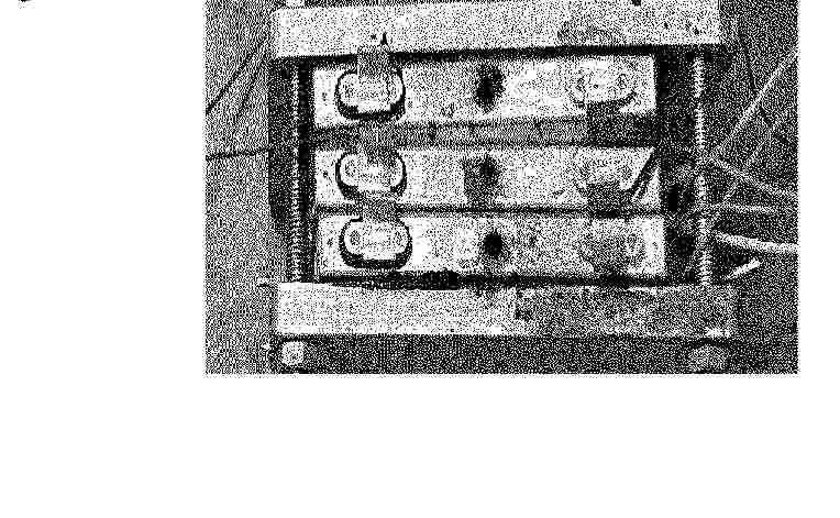
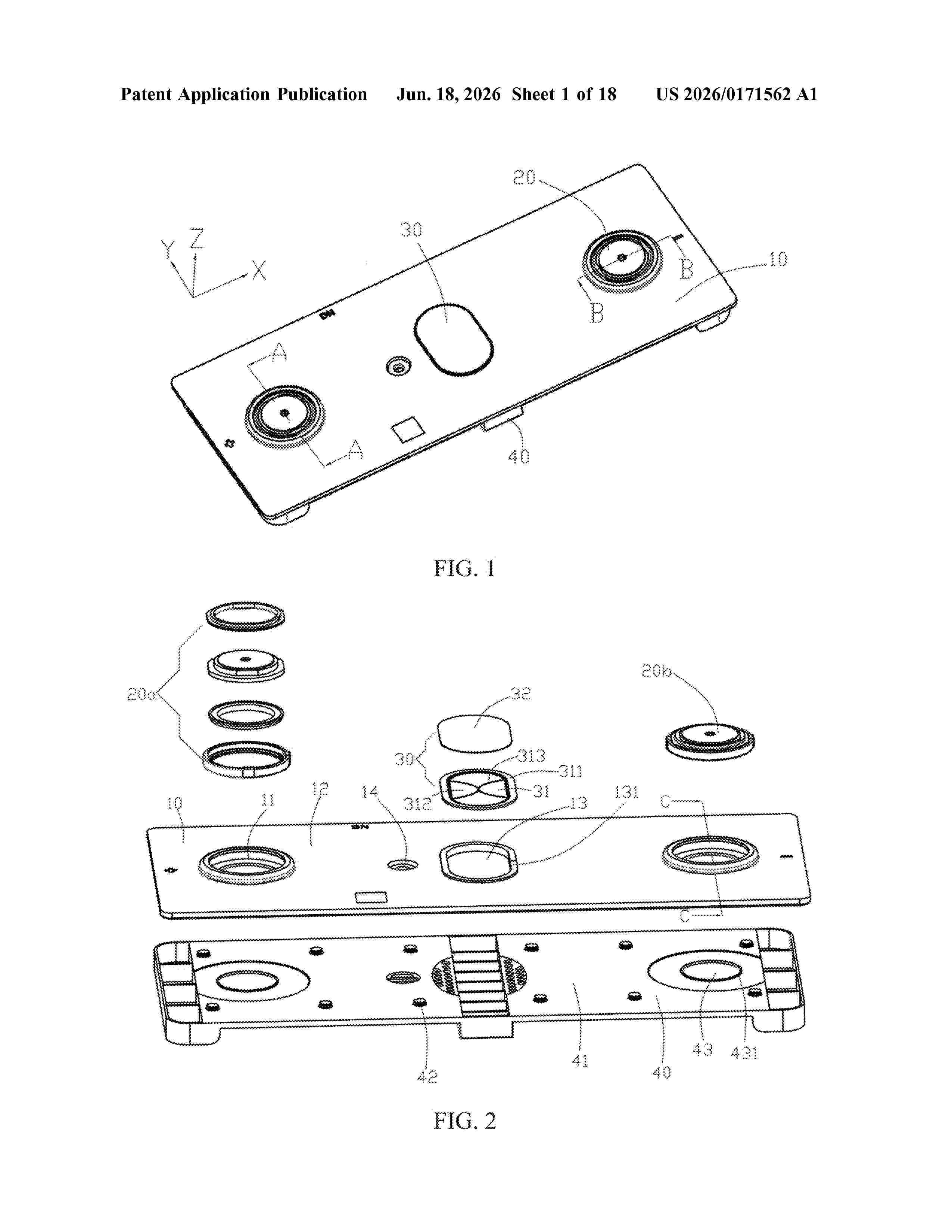
Resumen de: US20260171562A1
A cover plate manufacturing method and a battery top cover are provided. The cover plate manufacturing method includes following steps: providing a metal sheet, and punching the metal sheet to form punched holes; flanging a portion of the metal sheet on a periphery of each of the punched holes to form a sidewall extending upward; shaping and flattening each sidewall to enable each sidewall to reach a predetermined state; and splitting a material of each sidewall to form a horizontal bottom wall and form cover plates with terminal holes.
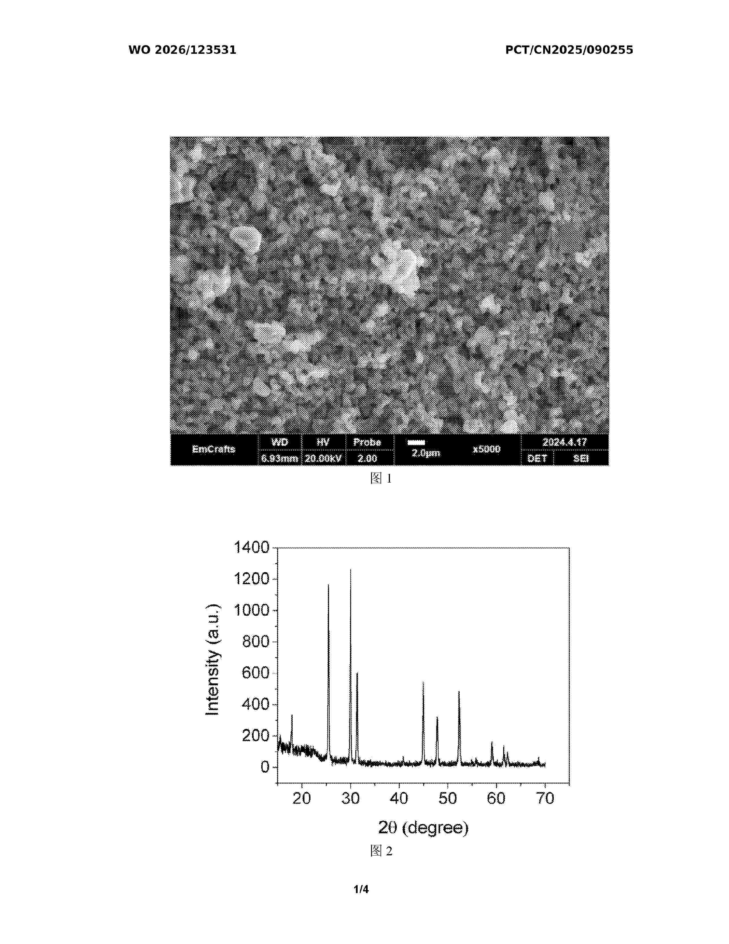
Resumen de: WO2026123531A1
An argyrodite-type solid electrolyte, a preparation method therefor, and use thereof. The molecular formula of the argyrodite-type solid electrolyte is Li5.5-xP1-xWxS4.5-3xO3xClyBr1.5-y. During preparation, raw materials are premixed according to a molar ratio and subjected to ball milling to obtain a solid electrolyte powder; then, the solid electrolyte powder is pressed into an electrolyte sheet, which is sintered to obtain the argyrodite-type solid electrolyte. The multifunctional electrolyte exhibits good stability in air while improving ionic conductivity.
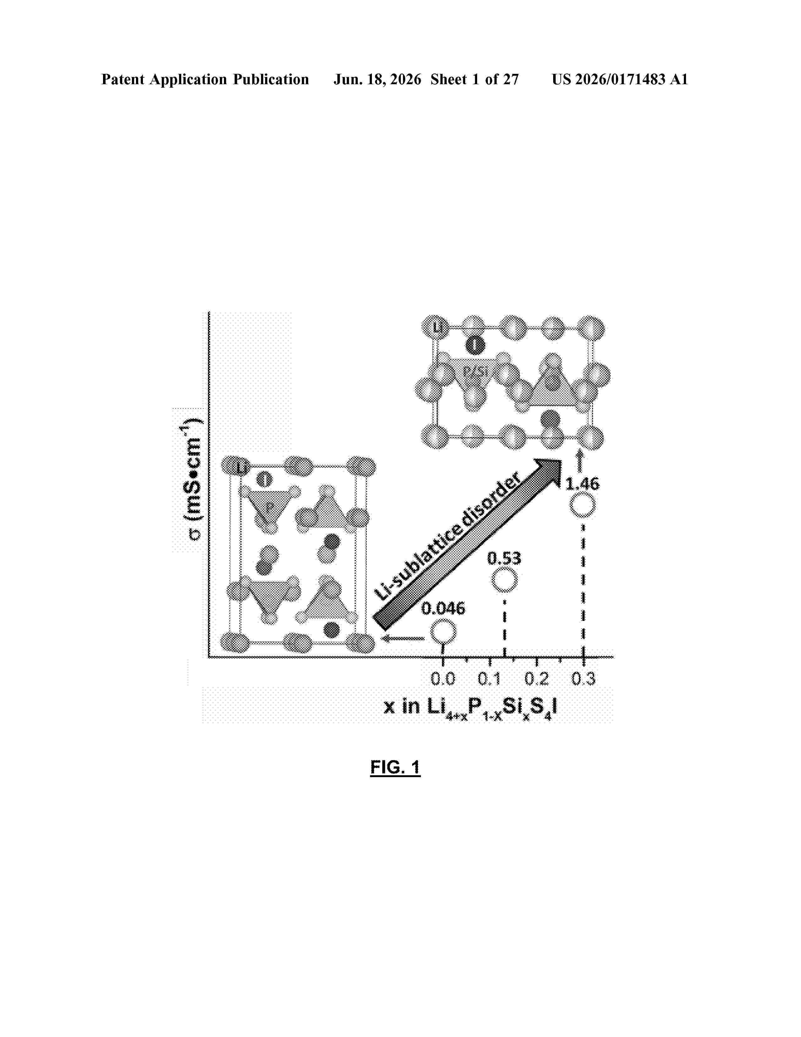
Resumen de: US20260171483A1
A material for use as a solid-state electrolyte, the material comprising a lithium thiophosphate halide having the formula Li4+xP1−xSixS4Z, where Z is a halide and/or a pseudohalide. In one aspect, Z is one or more of I−, Br−, BH4−, BF4−, NH2−, or N3−. In one aspect, 0.1
Resumen de: US20260171418A1
0000 The present disclosure relates to a polymer solid electrolyte composition for a lithium secondary battery and a use thereof. Particularly, the present disclosure relates to a polymer solid electrolyte composition for a lithium secondary battery, a polymer solid electrolyte for a lithium secondary battery, and a lithium secondary battery. The present disclosure can simultaneously improve the ionic conductivity and mechanical strength of a polymer electrolyte.
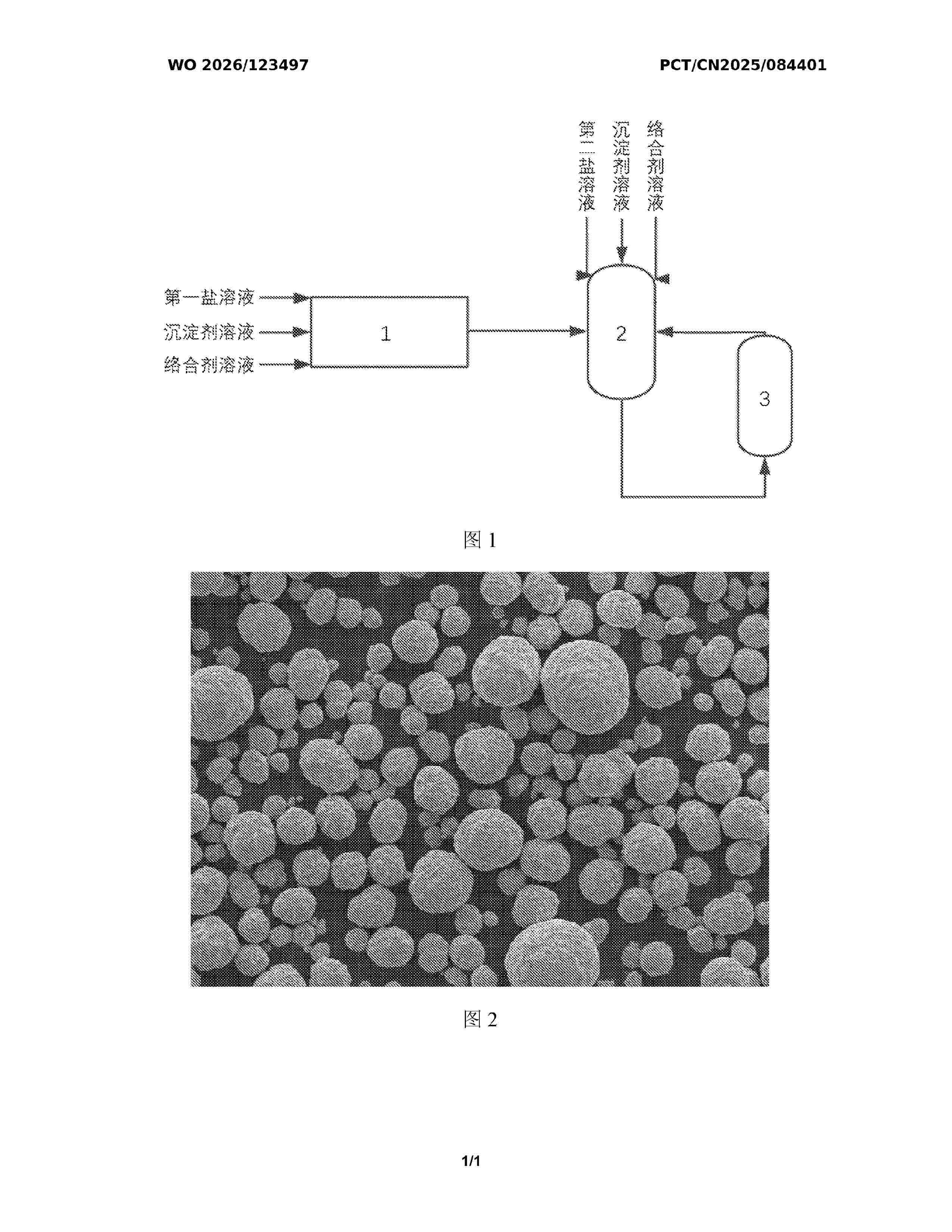
Resumen de: WO2026123497A1
A production apparatus and method for a core-shell precursor having a normally distributed particle size. The production apparatus comprises a homogenization reactor (1), a stirring reactor (2), and a thickener (3) that are sequentially connected by means of pipes, and the thickener (3) is connected back to the stirring reactor (2) by means of a pipe, so as to form a material circulation loop. The production apparatus uses a continuous method to produce a core-shell precursor having a normally distributed particle size. In the production method, the homogenization reactor (1) and the stirring reactor (2) are used to synchronously perform a coprecipitation reaction, and the thickener (3) is used to achieve continuous reaction and particle size control, thereby obtaining the core-shell precursor having the normally distributed particle size.
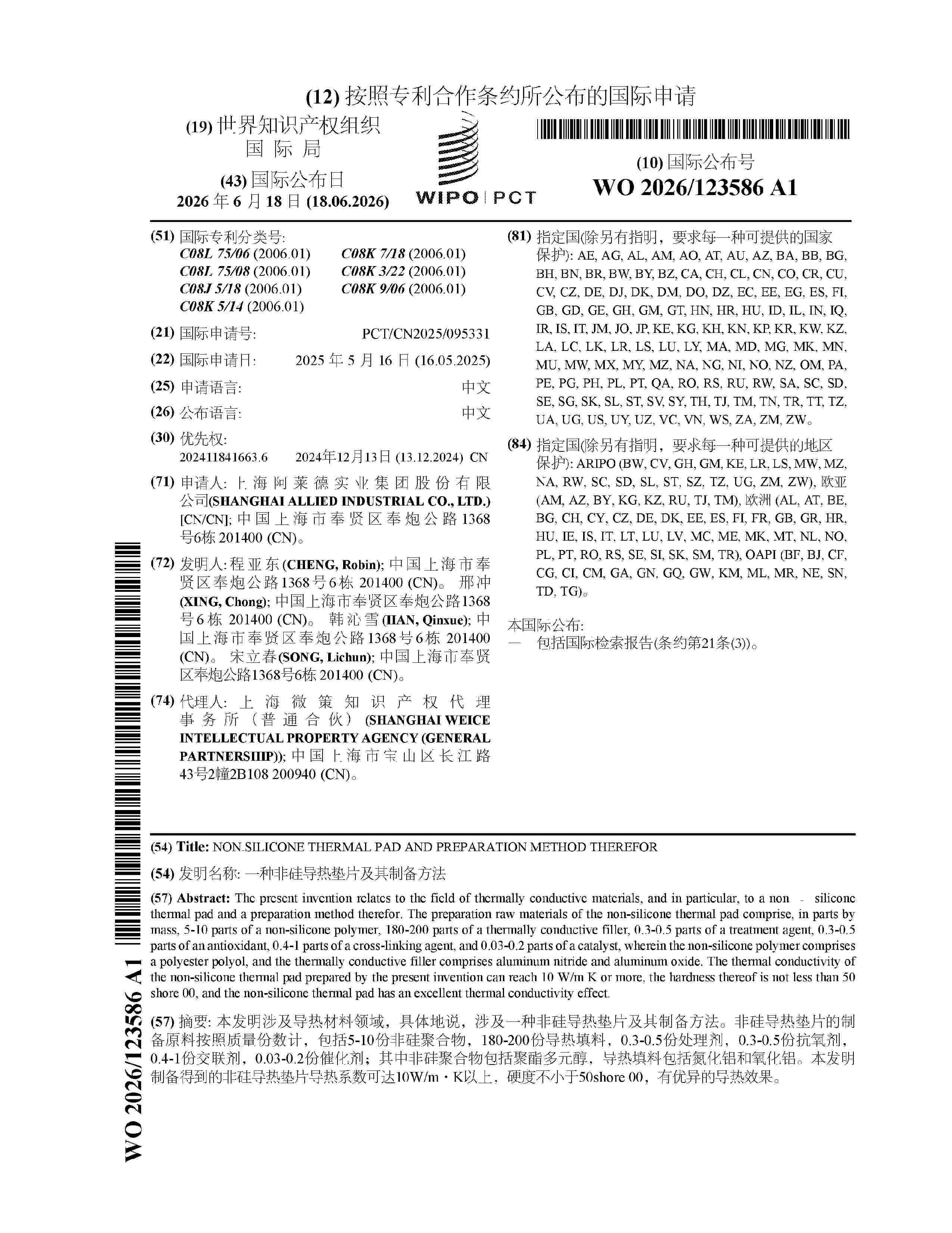
Resumen de: WO2026123586A1
The present invention relates to the field of thermally conductive materials, and in particular, to a non‑silicone thermal pad and a preparation method therefor. The preparation raw materials of the non-silicone thermal pad comprise, in parts by mass, 5-10 parts of a non-silicone polymer, 180-200 parts of a thermally conductive filler, 0.3-0.5 parts of a treatment agent, 0.3-0.5 parts of an antioxidant, 0.4-1 parts of a cross-linking agent, and 0.03-0.2 parts of a catalyst, wherein the non-silicone polymer comprises a polyester polyol, and the thermally conductive filler comprises aluminum nitride and aluminum oxide. The thermal conductivity of the non-silicone thermal pad prepared by the present invention can reach 10 W/m K or more, the hardness thereof is not less than 50 shore 00, and the non-silicone thermal pad has an excellent thermal conductivity effect.
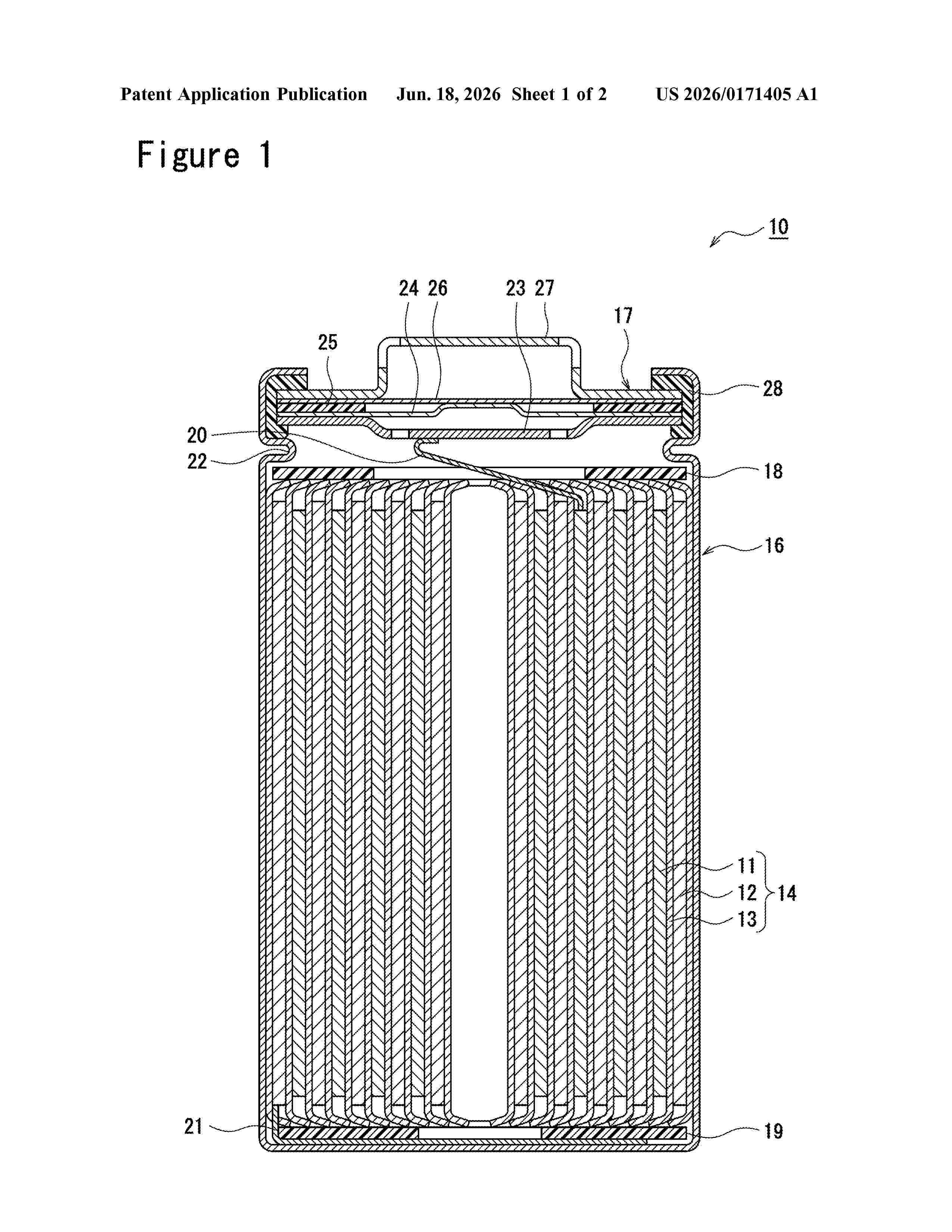
Resumen de: US20260171405A1
0000 According to an exemplary embodiment, the negative electrode active material for nonaqueous electrolyte secondary batteries is a composite particle comprising: an alkali aluminate phase containing two or more alkali metal elements and Al; a silicon phase that is dispersed in the alkali aluminate phase; and a conductive layer that is formed on the surface of a base particle comprising the alkali aluminate phase and the silicon phase.
Nº publicación: US20260171402A1 18/06/2026
Solicitante:
LG ENERGY SOLUTION LTD [KR]
LG ENERGY SOLUTION, LTD.
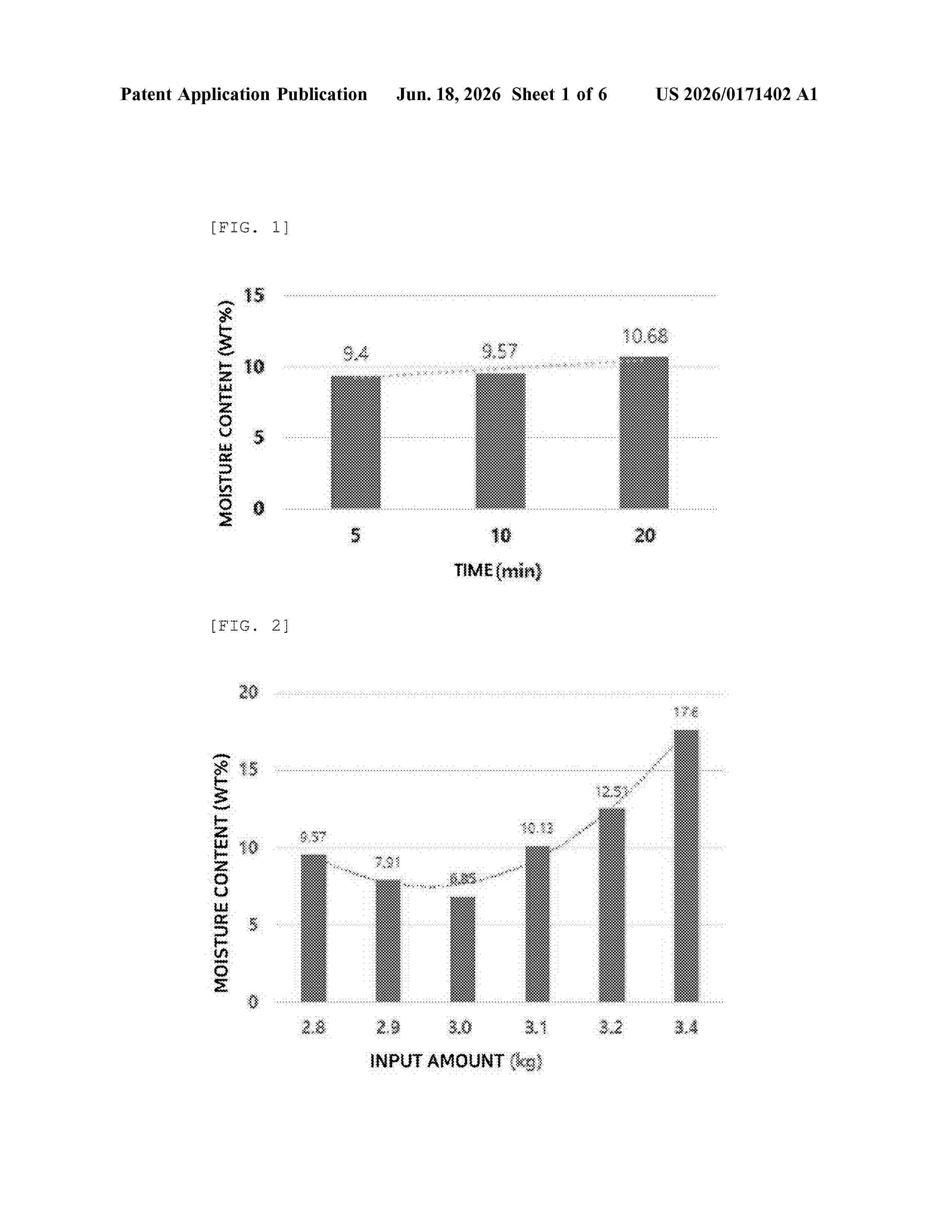
Resumen de: US20260171402A1
The present disclosure relates to a method of recycling a cathode active material and a recycled cathode active material prepared using the method. The method includes: (a) recovering a cathode active material by heat-treating a waste cathode including a current collector and a cathode active material layer coated thereon at 300 to 650° C. under an air or oxygen atmosphere; (b) mixing the recovered cathode active material and a washing solution; (c) filtering the cathode active material mixed with the washing solution; and (d) adding a lithium precursor to the filtered cathode active material and performing annealing at 400 to 1000° C. in air, wherein, in step (c), the filtered cathode active material has a moisture content of 5 to 10.5% by weight, and a recycled cathode active material prepared using the method.
 BOPI
BOPI
 Sede Electrónica