Si deseas distinguir tus productos, servicios o ambos de los de otra empresa, es posible que necesites una marca o nombre comercial. Descubre qué son, en qué consiste su procedimiento de registro y qué implica.

Información sobre los plazos de presentación de solicitudes de transformación de marcas de la Unión Europea en marca nacional española. Más información


Si tienes un nuevo dispositivo, producto o procedimiento que resuelva un problema técnico o tenga una ventaja práctica, existen distintas formas de protegerlo en España y en otros países. Descubre cómo hacerlo.

¿Tu innovación reside en la estética, la ornamentación o la apariencia de tu producto? Protégela mediante un diseño industrial. Descubre qué derechos confiere el registro y cómo realizar la tramitación.

Las indicaciones geográficas protegen el nombre de un producto originario de una zona geográfica, a la cual le debe una determinada calidad, reputación u otra característica. Descubre qué son, en qué consiste su procedimiento de registro y qué beneficios conceden.

Las patentes publicadas en todo el mundo son una valiosa fuente de información científica, técnica y comercial.

Si eres emprendedor/a o una empresa y quieres potenciar y mejorar la rentabilidad de tu negocio protegiendo de forma adecuada los activos intangibles de tu organización, en este espacio encontrarás lo necesario.


 1603
resultados
1603
resultados
 Última actualización
24/06/2026 [07:18:00]
Última actualización
24/06/2026 [07:18:00]


 Resultados 100 a 125 de 1603

Resumen de: US20260167814A1
The present invention relates to a polymer composition, and a slurry composition, a separator and a secondary battery comprising same, the polymer composition comprising: a particle-type polymer comprising a carboxyl group or an alcohol group; and a chain-type polymer comprising a carboxyl group or an alcohol group (if the particle-type polymer comprises the carboxyl group, the chain-type polymer comprises the alcohol group and, if the particle-type polymer comprises the alcohol group, the chain-type polymer comprises the carboxyl group).

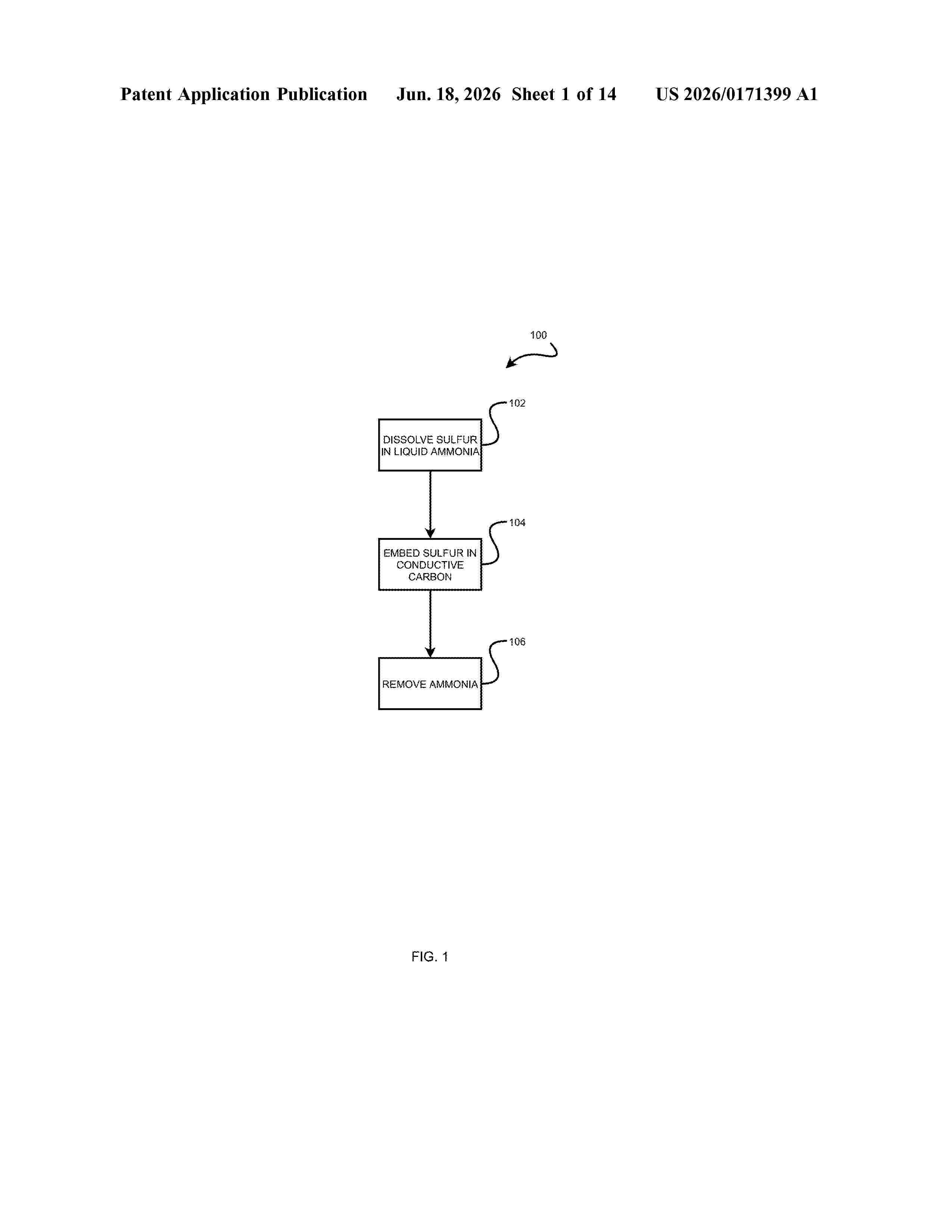
Resumen de: US20260171399A1
A method for embedding sulfur into conductive carbon is provided. Elemental sulfur is dissolved in liquid ammonia to form a sulfur-ammonia solution. Conductive carbon is soaked in the sulfur-ammonia solution to embed the conductive carbon with the dissolved sulfur. The liquid ammonia in the sulfur-ammonia solution can be removed as gaseous ammonia to yield sulfur-embedded conductive carbon. The sulfur-embedded conductive carbon can be used to manufacture sulfur cathodes. Such sulfur cathodes and batteries incorporating such sulfur cathodes are provided.
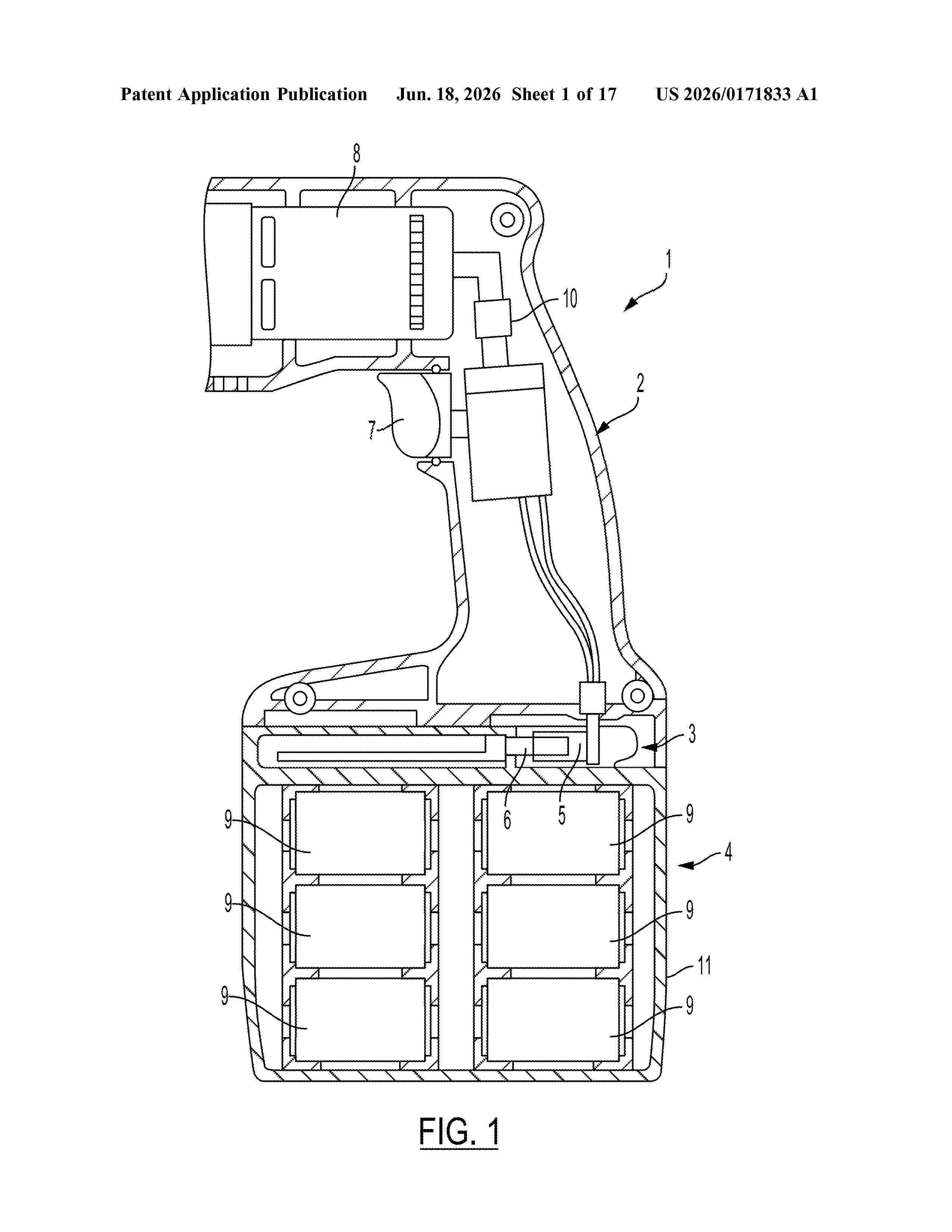
Resumen de: US20260171833A1
0000 The present disclosure is directed to charging a battery pack by measuring an electrical impedance value of a battery pack by applying a sinusoidal AC excitation signal to a plurality of battery cells of the battery pack, measuring a total impedance value of the battery pack, obtaining a chemical impedance value of the battery pack based on the electrical impedance value and the total impedance value, and adjusting a charge current applied to the battery pack based on the chemical impedance value of the battery pack.
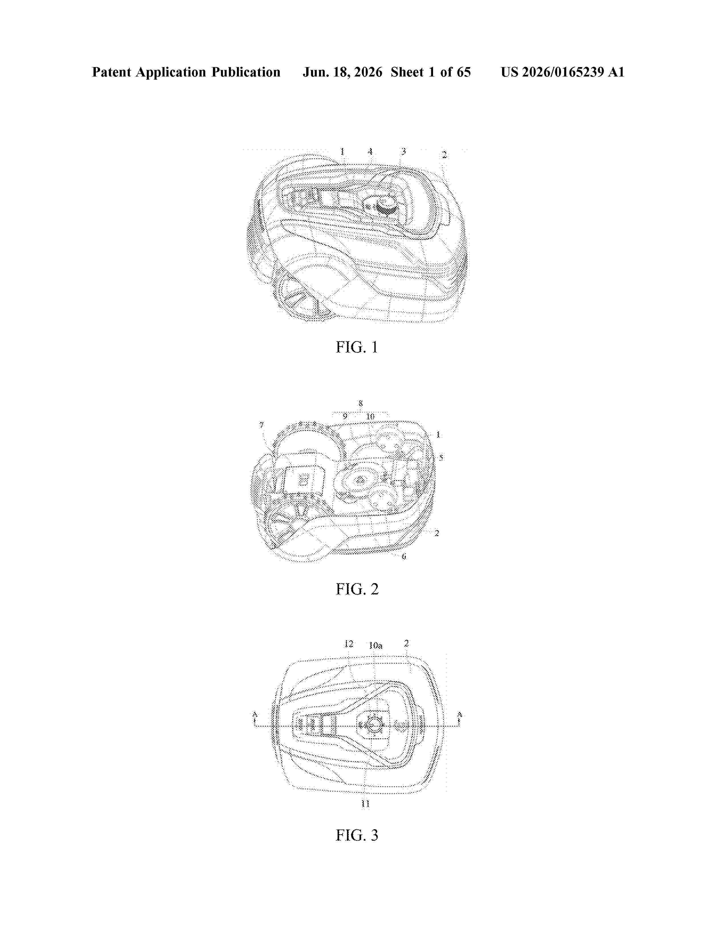
Resumen de: US20260165239A1
A mower is provided and includes: a housing; a movable upper cover, disposed on the housing; and a cutting assembly, disposed on the housing. The cutting assembly includes a blade carrier assembly, and the blade carrier assembly includes a blade carrier and a blade. The blade carrier includes a disc body and a blade receiving groove recessed inwardly from an edge of the disc body along an axial direction of the disc body. The blade is mounted in the blade receiving groove and arranged to be that the blade is not protruded out of the blade receiving groove in the axial direction of the disc body.
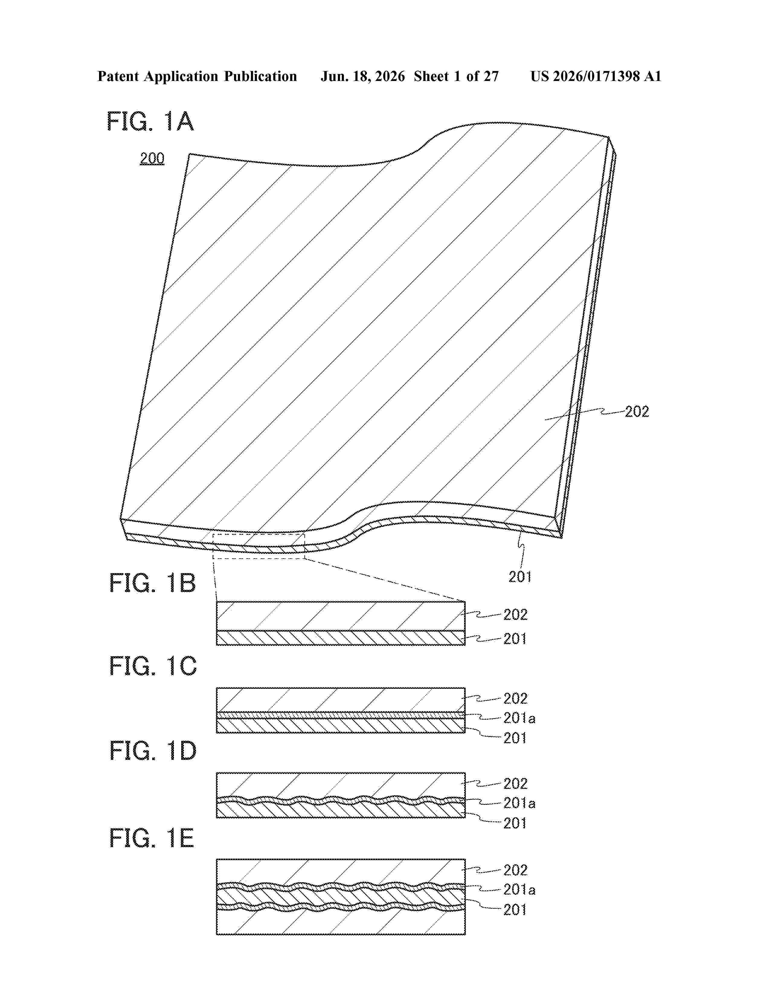
Resumen de: US20260171398A1
A secondary battery with favorable cycle performance is provided. Alternatively, a secondary battery with higher capacity is provided. A positive electrode active material layer including a first graphene layer, a second graphene layer, and a positive electrode active material. The first graphene layer includes a first region covering the positive electrode active material. The second graphene layer includes a second region covering the positive electrode active material and a third region overlapping with the first region. The first region includes a plane positioned between the positive electrode active material and the third region and formed of arranged six-membered carbon rings. The positive electrode active material includes a fourth region with a layered rock-salt structure. A lithium layer with a layered rock-salt structure included in the fourth region is substantially perpendicular to the plane formed of six-membered carbon rings and included in the second region.
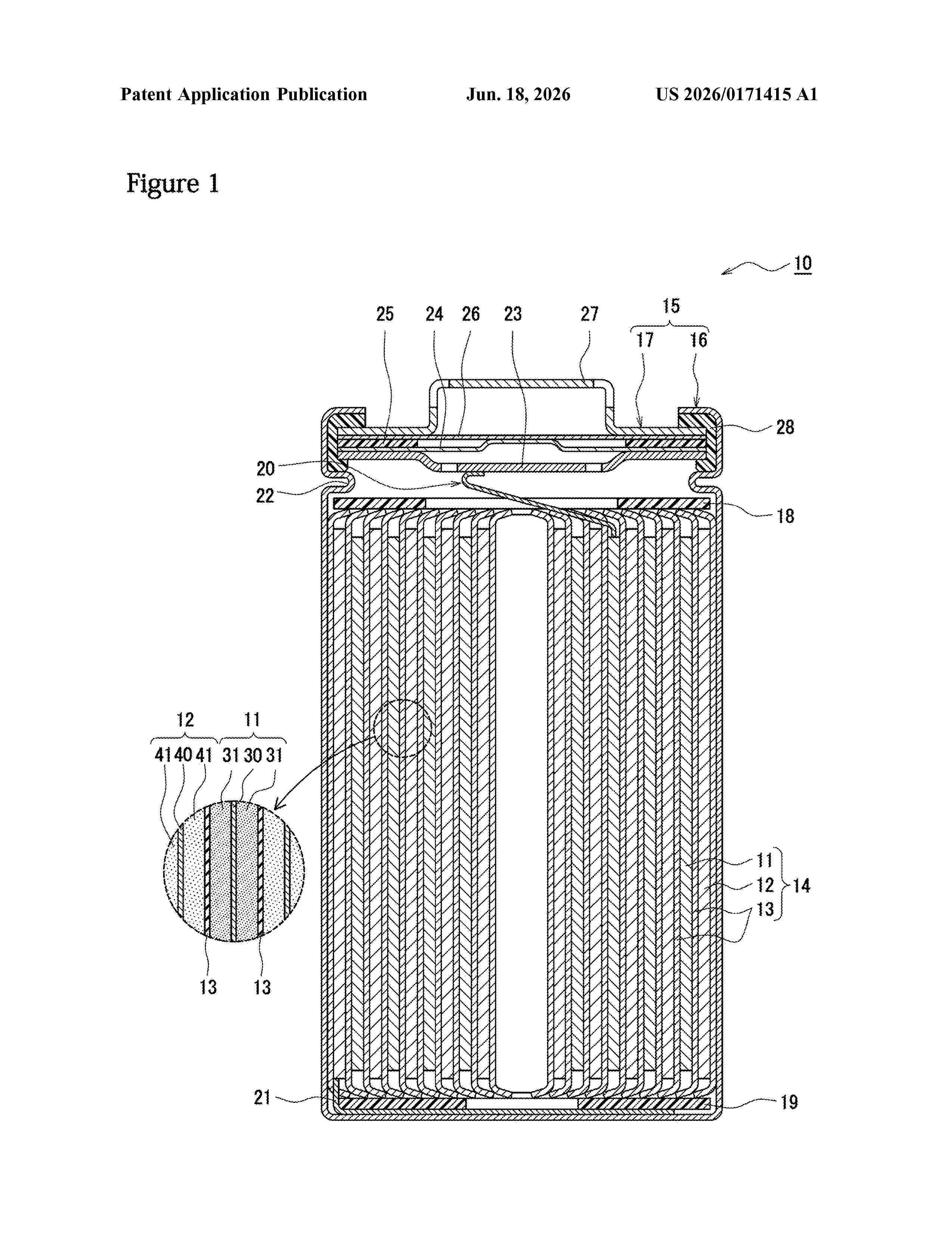
Resumen de: US20260171415A1
The present invention provides a positive electrode active material which has improved capacity retention rate at room temperature. A negative electrode contained in a nonaqueous electrolyte secondary battery according to the present invention contains a negative electrode active material and a lithium sulfonate salt represented by general formula (I); and the particle diameter of the lithium sulfonate salt is 1 nm to 1,000 nm. (In the formula, R presents an n-valent aliphatic hydrocarbon group having 1 to 5 carbon atoms; and n represents 1 or 2.)
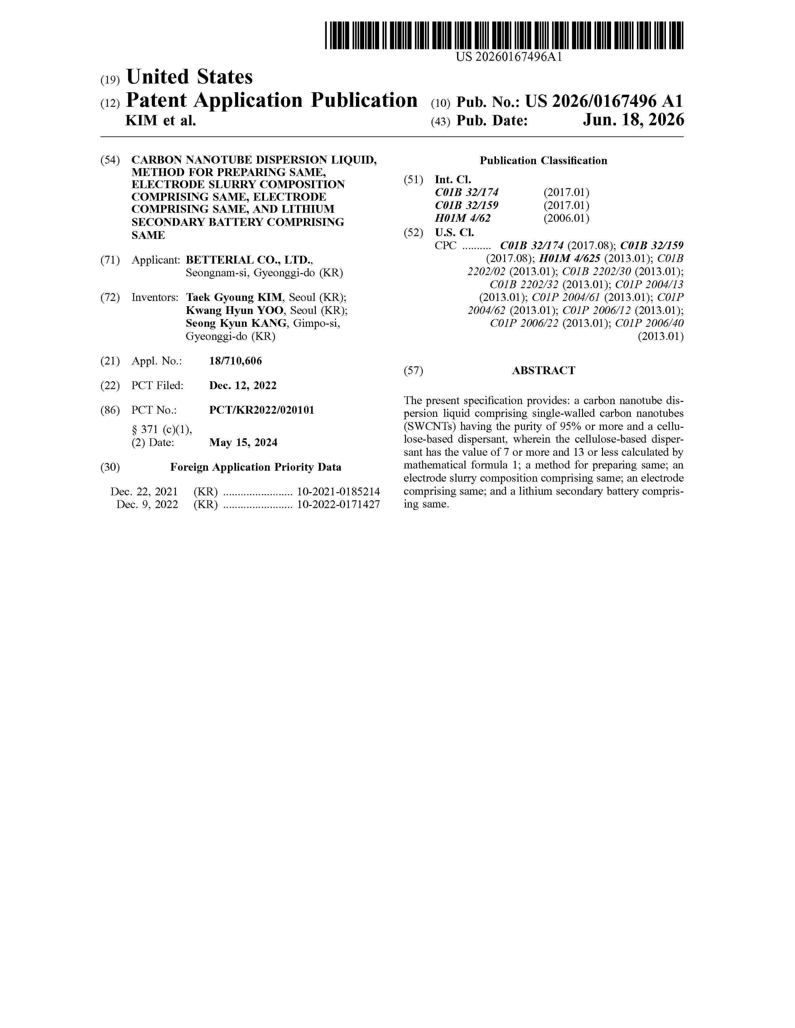
Resumen de: US20260167496A1
The present specification provides: a carbon nanotube dispersion liquid comprising single-walled carbon nanotubes (SWCNTs) having the purity of 95% or more and a cellulose-based dispersant, wherein the cellulose-based dispersant has the value of 7 or more and 13 or less calculated by mathematical formula 1; a method for preparing same; an electrode slurry composition comprising same; an electrode comprising same; and a lithium secondary battery comprising same.
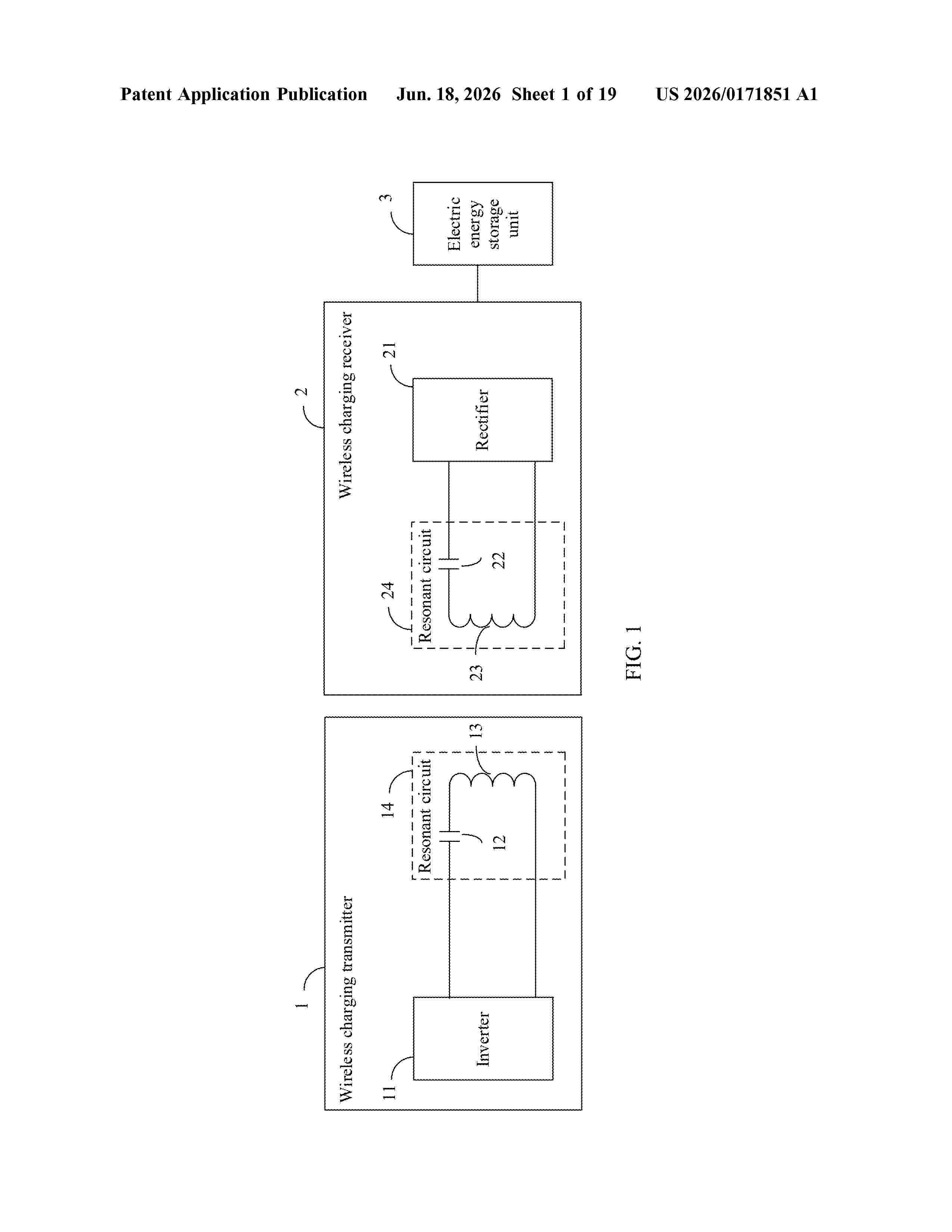
Resumen de: US20260171851A1
0000 The present disclosure provides a rectifier, an inverter, and a wireless charging device. The rectifier includes a signal conversion unit and a switchable capacitor unit that are mutually coupled. The switchable capacitor unit is configured to switch a rectification mode of the rectifier. The rectification mode may include but is not limited to any one of the following: a voltage multiplier rectification mode or a full-bridge rectification mode. Therefore, a variable dynamic range of the output voltage of the rectifier provided in embodiments of the present disclosure is extended.
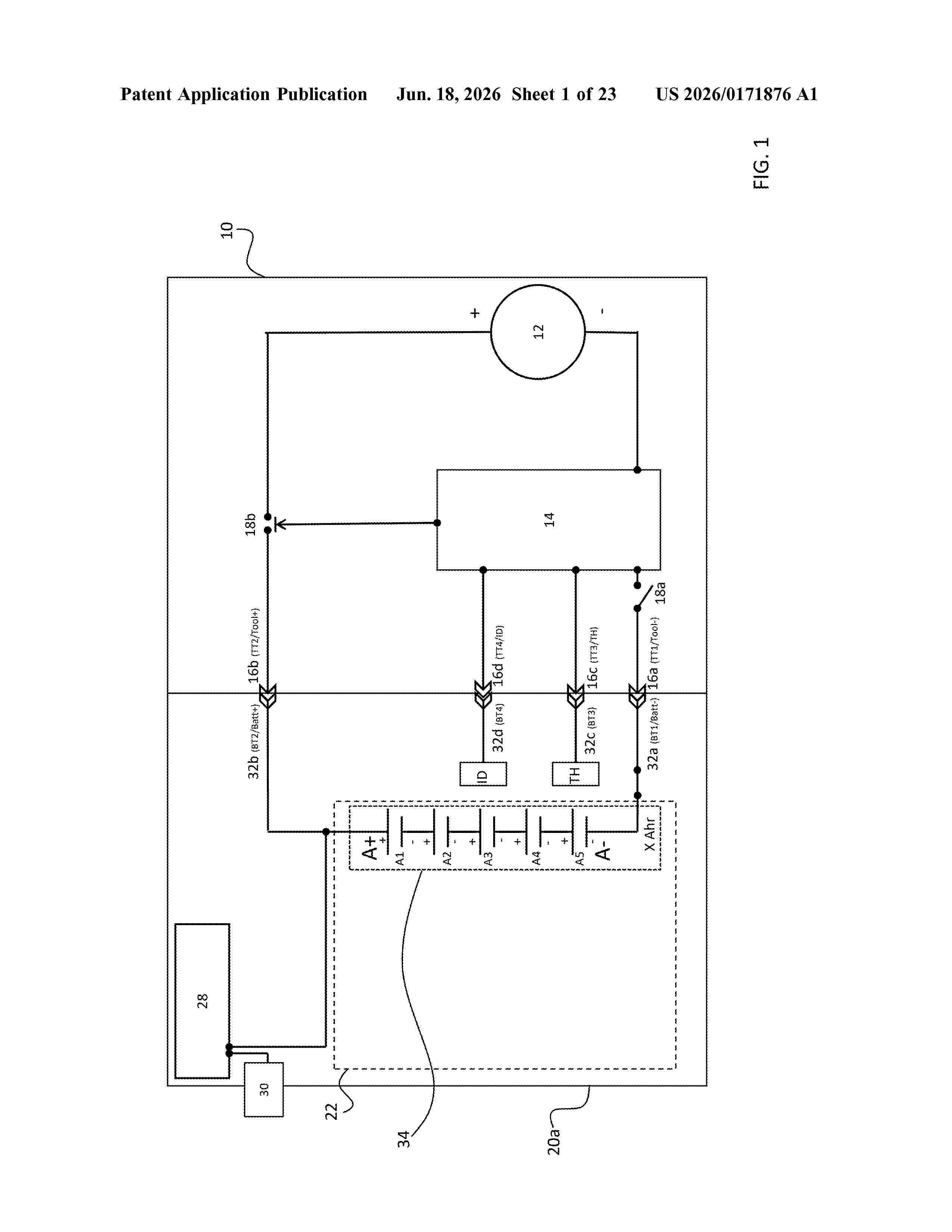
Resumen de: US20260171876A1
A power tool system includes a power tool having a tool housing. The tool housing includes a battery pack receptacle having a set of tool terminals. A brushless motor includes an output shaft operably coupled to drive a tool element, a stator having an outer diameter of approximately 60 mm to approximately 80 mm, and a stack length of approximately 75% to approximately 125% of the outer diameter of the stator. A controller is operably connected to the set of tool terminals and to the brushless motor to control power delivery to the brushless motor. A battery pack includes a battery pack housing connectable to the battery pack receptacle on the tool housing and a set of battery cells. The set of battery cells includes at least 15 battery cells each having a nominal voltage of approximately 3.6V and an impedance of approximately ≤13 mΩ. A set of battery pack terminals is connectable to the set of tool terminals. The battery pack has a nominal voltage of at least approximately 54V and the brushless motor is operable under load to output a power of between approximately 3000 W and approximately 5000 W.
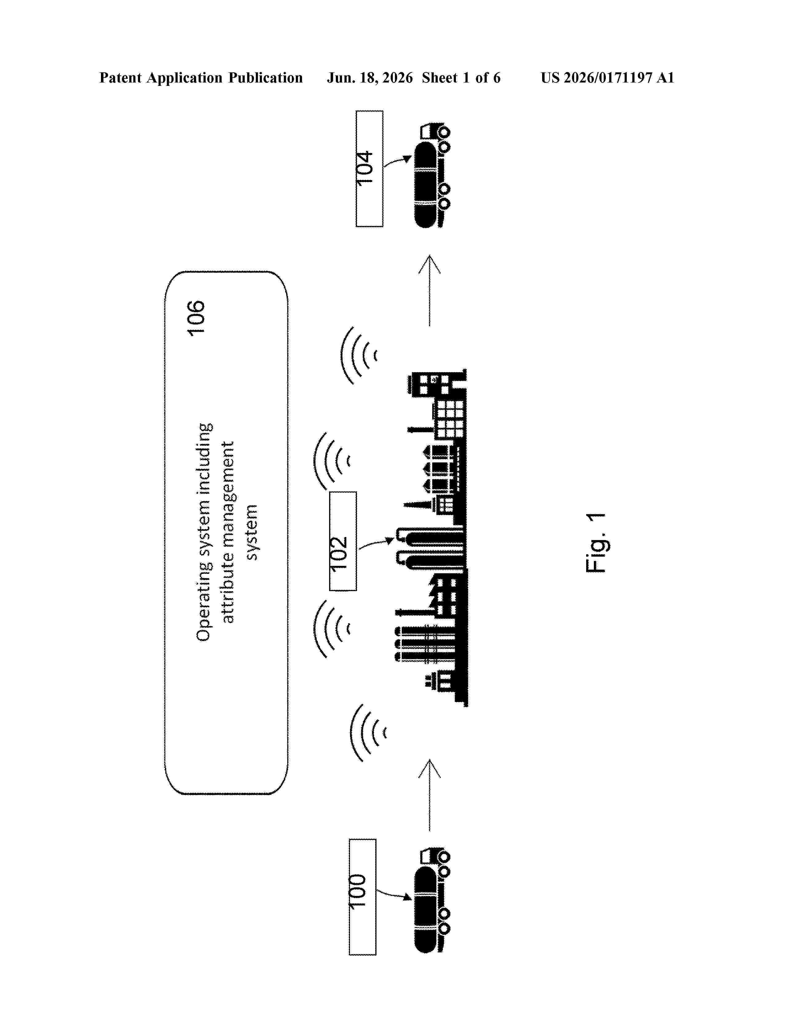
Resumen de: US20260171197A1
Disclosed herein are systems for producing a care composition ingredient associated with a digital asset, methods for producing a care composition ingredient associated with a digital asset, apparatuses for generating a digital asset, computer-implemented methods for generating a chemical passport, computer program elements for generating a digital asset, uses of a care composition ingredient associated with a digital asset, uses of a digital asset, products produced from the care composition ingredient and associated with a digital asset, a digital asset including one or more decentral identifier(s) and data related to the environmental impact data, apparatuses for producing a product associated with the digital asset and methods for producing a product associated with the digital asset.
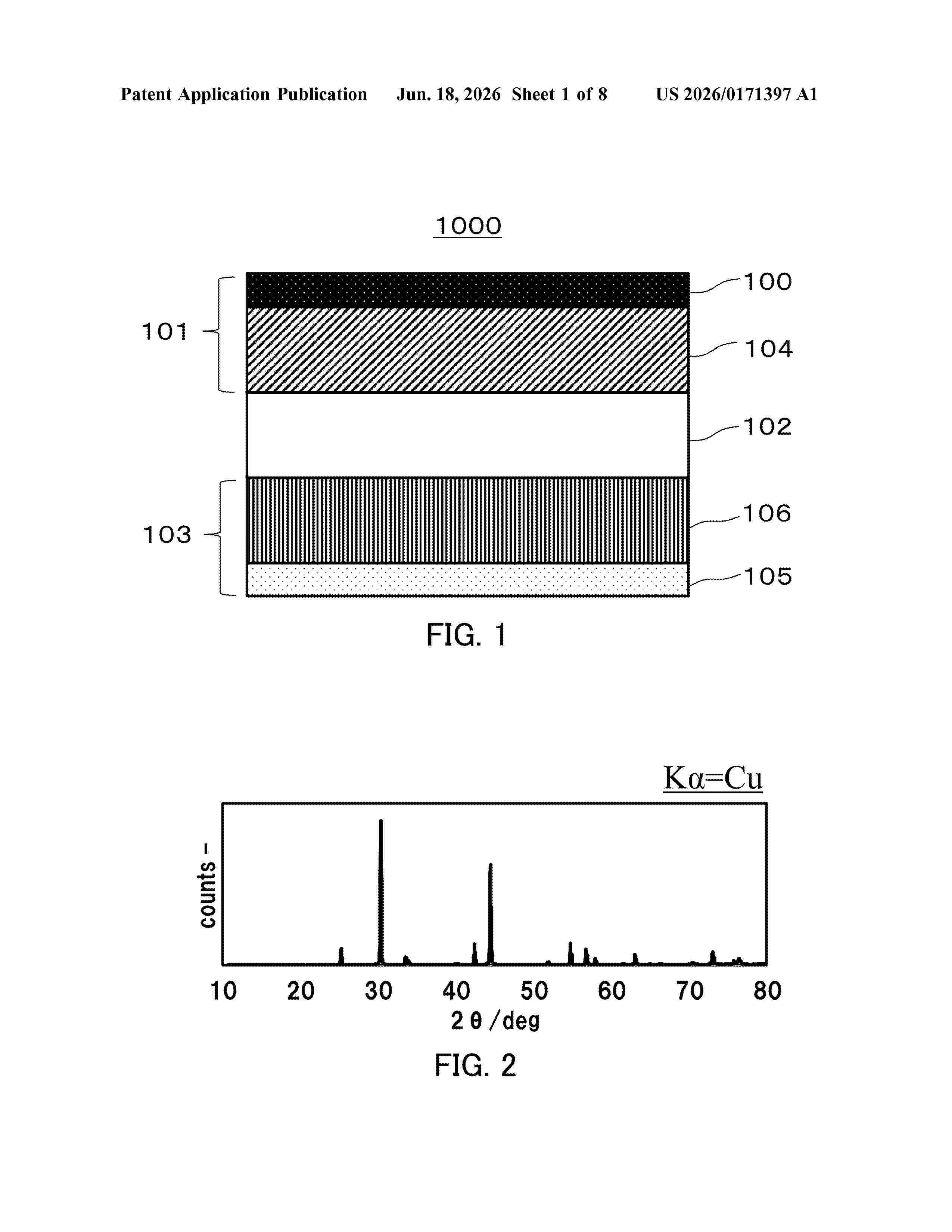
Resumen de: US20260171397A1
0000 A battery 1000 according to the present disclosure includes a positive electrode 103, a negative electrode 101, and an electrolyte layer 102 positioned between the positive electrode 103 and the negative electrode 101. The positive electrode 103 includes a positive electrode active material layer 106. The positive electrode active material layer 106 includes a compound, and the compound includes a transition metal element and an oxoanion and is capable of occluding and releasing lithium ions. The negative electrode 101 includes a negative electrode current collector 100 and a negative electrode active material layer 104. The negative electrode active material layer 104 includes an alloy, and the alloy includes Bi and Ni.
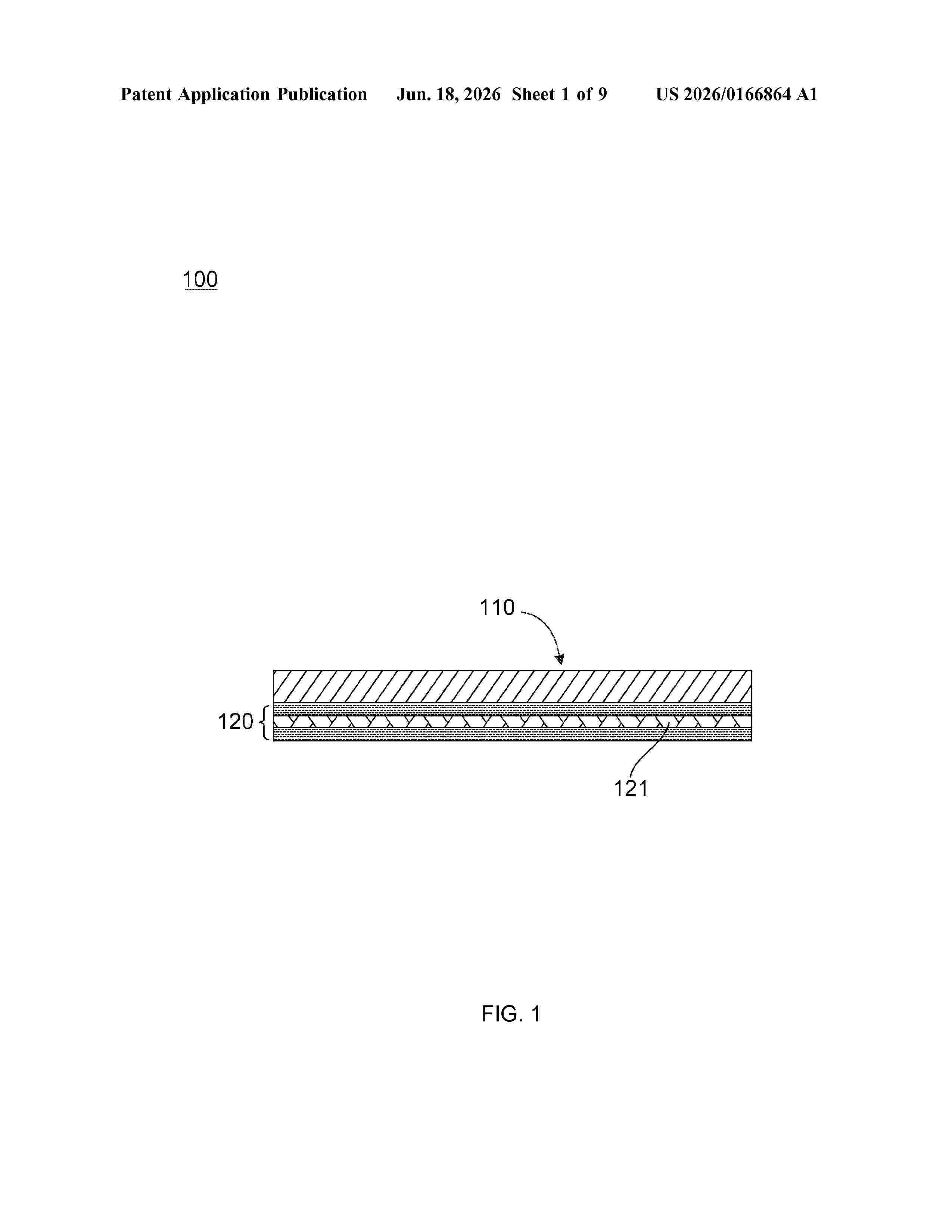
Resumen de: US20260166864A1
0000 The present application discloses a composite fire insulation sheet, a composite plate, a battery pack housing and a battery pack. The composite fire insulation sheet comprises a first glass fiber sheet and a first aerogel composite expansion fire insulation layer. The first aerogel composite expansion fire insulation layer is arranged on at least one surface of the first glass fiber sheet and has a second glass fiber sheet. According to the composite fire insulation sheet of this application, the expansion fireproof composition plays the role of flame retardant and fire prevention, while the aerogel composition is used to endow the sheet with excellent heat insulation property, such that the sheet can also perform the strong heat insulation performance.
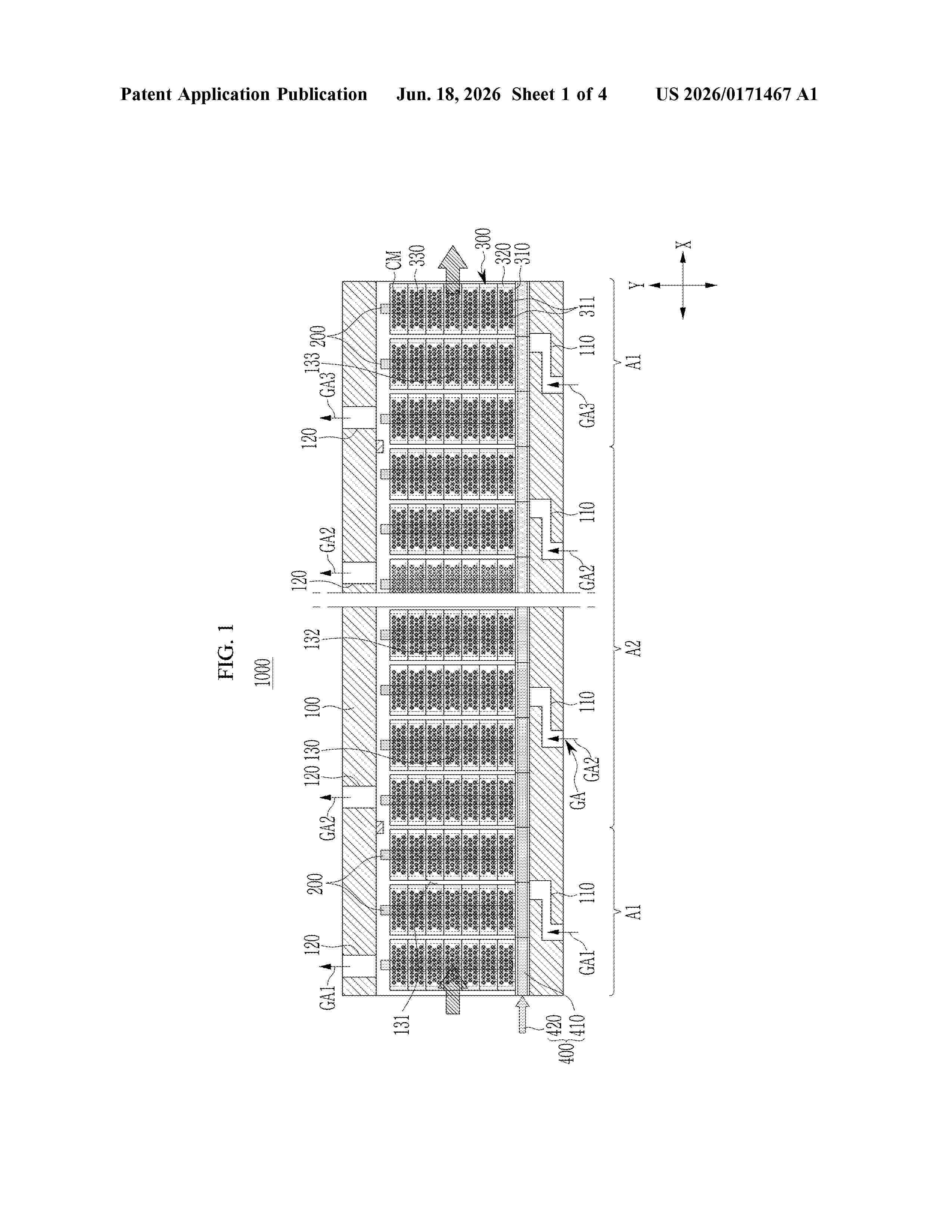
Resumen de: US20260171467A1
0000 Provided is an apparatus for firing a cathode material of a secondary battery by moving the cathode material in a horizontal direction, including: a firing furnace including an air supply part which is placed in a lower portion and to which gas is supplied, an exhaust part which is placed in an upper portion and from which the gas is exhausted, and a firing space which is placed between the air supply part and the exhaust part and extended in a vertical direction intersecting the horizontal direction; a heater which heats the firing space of the firing furnace; a plurality of saggers which store the cathode material for a secondary battery and are stacked in the vertical direction in the firing space; and a pusher which has the plurality of saggers settled therein and moves the plurality of saggers in the horizontal direction.
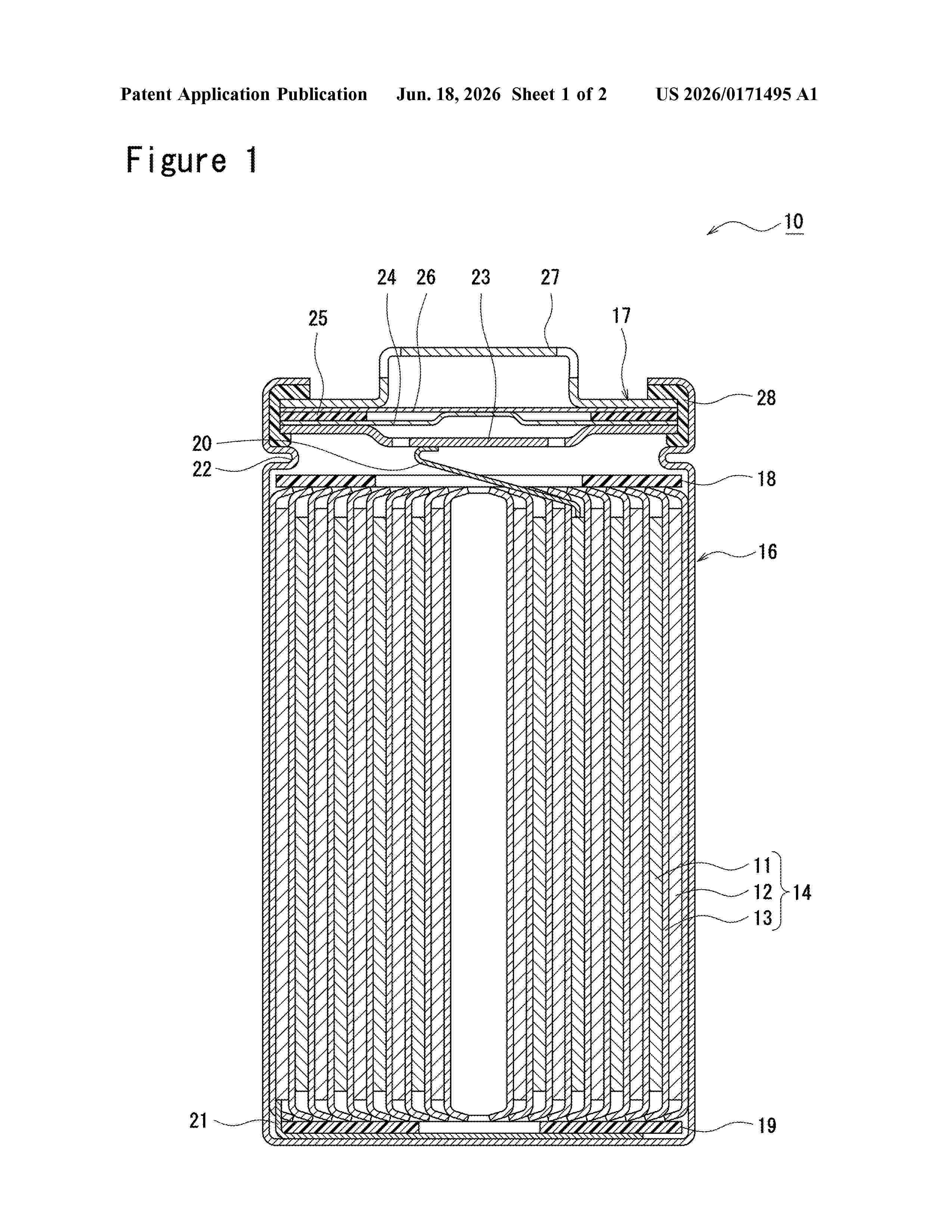
Resumen de: US20260171495A1
0000 In a non-aqueous electrolyte secondary battery according to one embodiment of the present invention, a positive electrode (11) has: a positive electrode core material (30); and a positive electrode mixture layer (31) formed on the surface of the positive electrode core material (30). The electrode mixture layer (31) contains, as a positive electrode active material, first lithium metal composite oxide particles that are non-aggregated particles having a volume-based median diameter of 2-10 μm, and second lithium metal composite oxide particles that are secondary particles that have a volume-based median diameter of 10-30 μm and that are each obtained by aggregation of primary particles having an average particle diameter from 50 nm to 2 μm. The first lithium metal composite oxide particles are contained more in a first region (31a ) than in a second region (31b ). A non-aqueous electrolyte contains a diisocyanate compound.
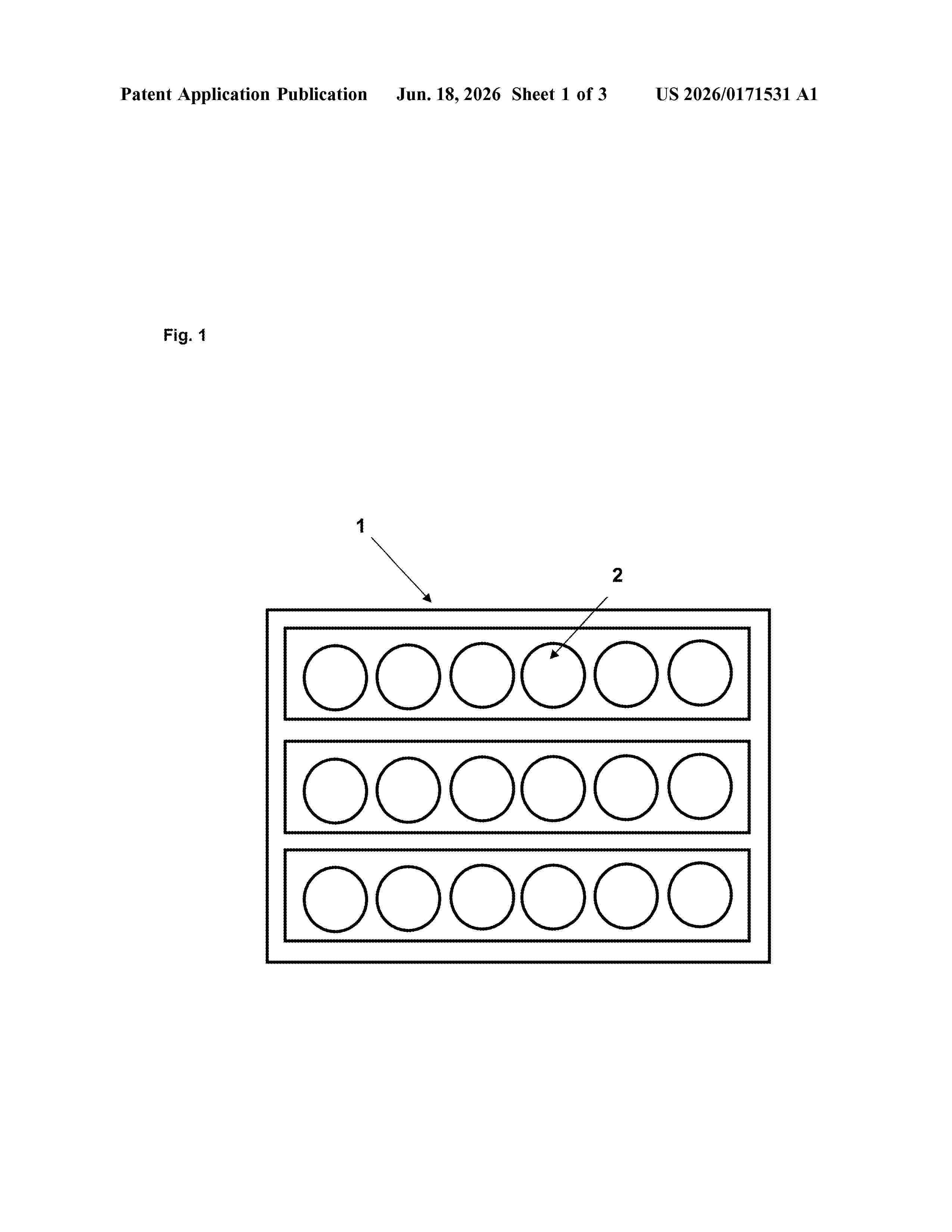
Resumen de: US20260171531A1
An energy supply device for a power tool, wherein the energy supply device comprises at least one cell. The at least one cell has a nominal capacity of at least 1.5 ampere hours, as well as a surface area A and a volume V. The surface area A of the at least one cell is greater than eight times the cube root of the square of the volume V of the at least one cell. In addition, a ratio of resistance and surface area of the at least one cell is less than 0.2 millionm/cm2. A power tool having a energy supply device is also provided.
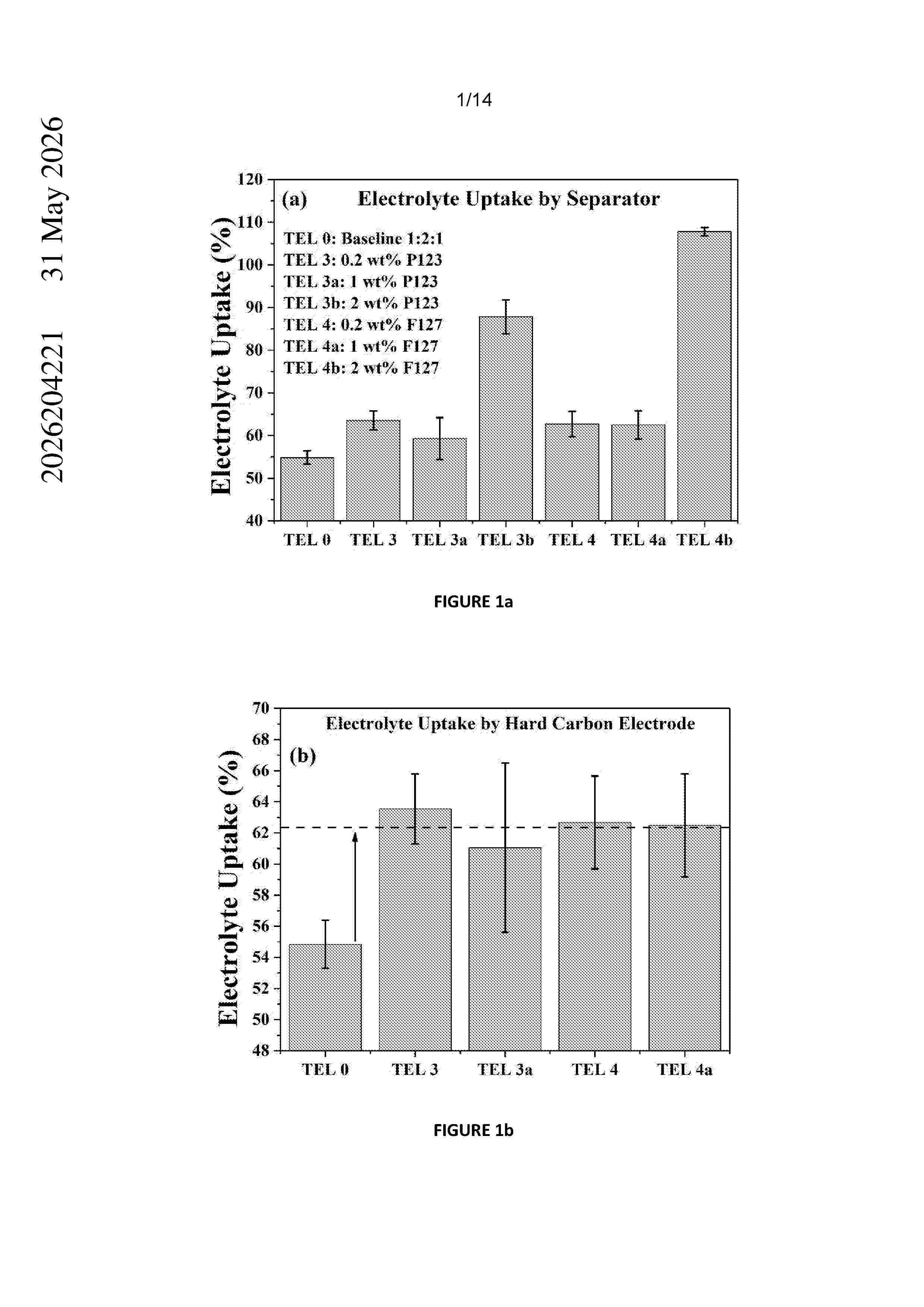
Resumen de: AU2026204221A1
The invention provides novel non-aqueous electrolyte compositions comprising: a) one or more sodium-containing compounds; and b) a solvent system which comprises: i) a first solvent component which comprises one or more organo carbonate-based solvents; and ii) a second solvent component which comprises one or more surfactants in an amount of >0.5 to 10% by weight of the solvent system, ay a y s u r f a c t a n t s i n a n a m o u n t o f > t o % b y w e i g h t o f t h e
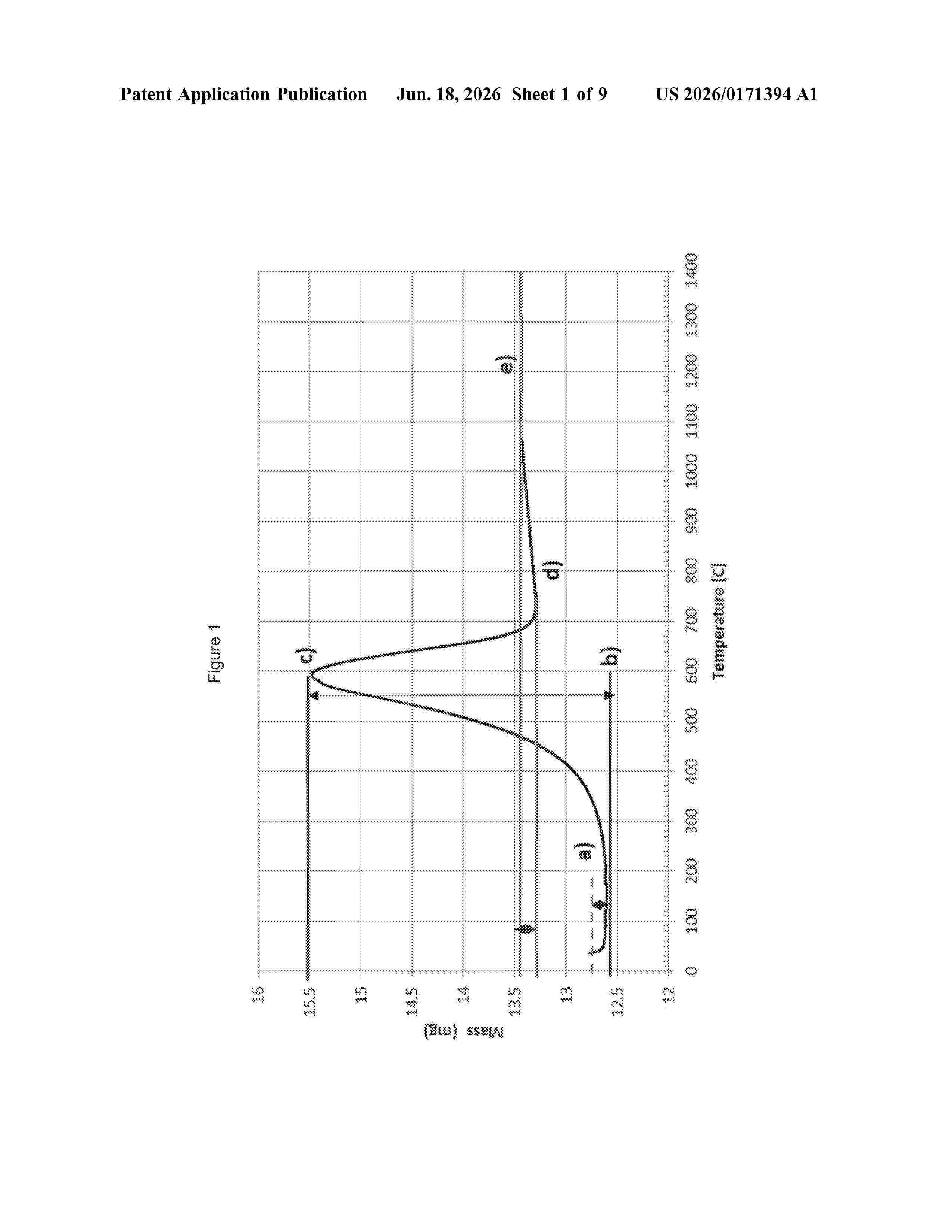
Resumen de: US20260171394A1
The invention provides methods for providing composite particles with a carbon coating and the resulting core-shell particulate material. The process comprises subjecting a plurality of precursor composite particles to a heat treatment in contact with a pyrolytic carbon precursor such that an outer shell of a pyrolytic conductive carbon material is formed on the precursor composite particles, wherein the heat treatment is carried out at a temperature of no more than 700° C.
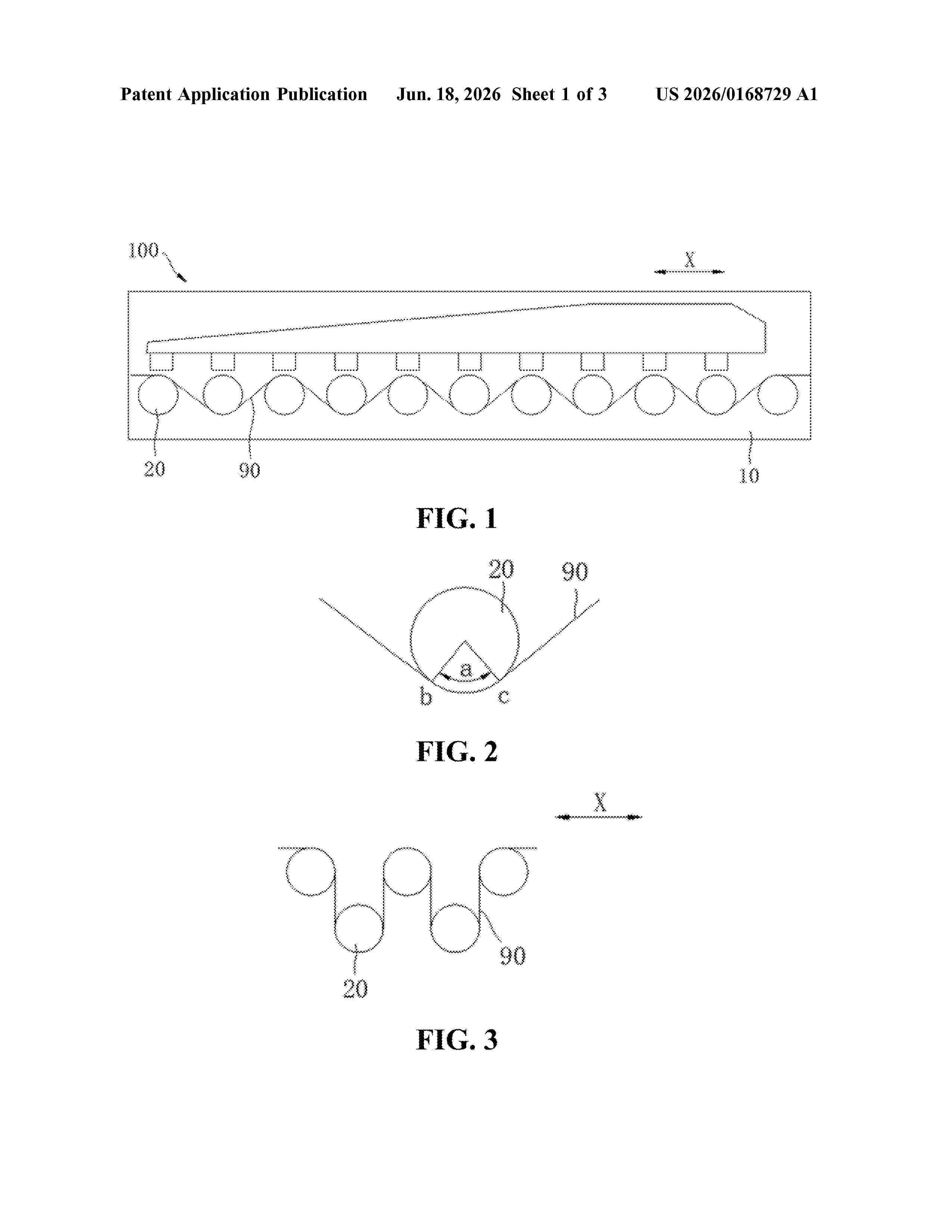
Resumen de: US20260168729A1
0000 An oven, which is used for heating an electrode plate, and the oven comprises a box body and a plurality of heating rollers. Among all the heating rollers, at least two adjacent heating rollers can rotate in opposite directions relative to the box body. All the heating rollers are arranged at intervals in the box body in a first direction, and all the heating rollers jointly support and guide the electrode plate to travel in the first direction.
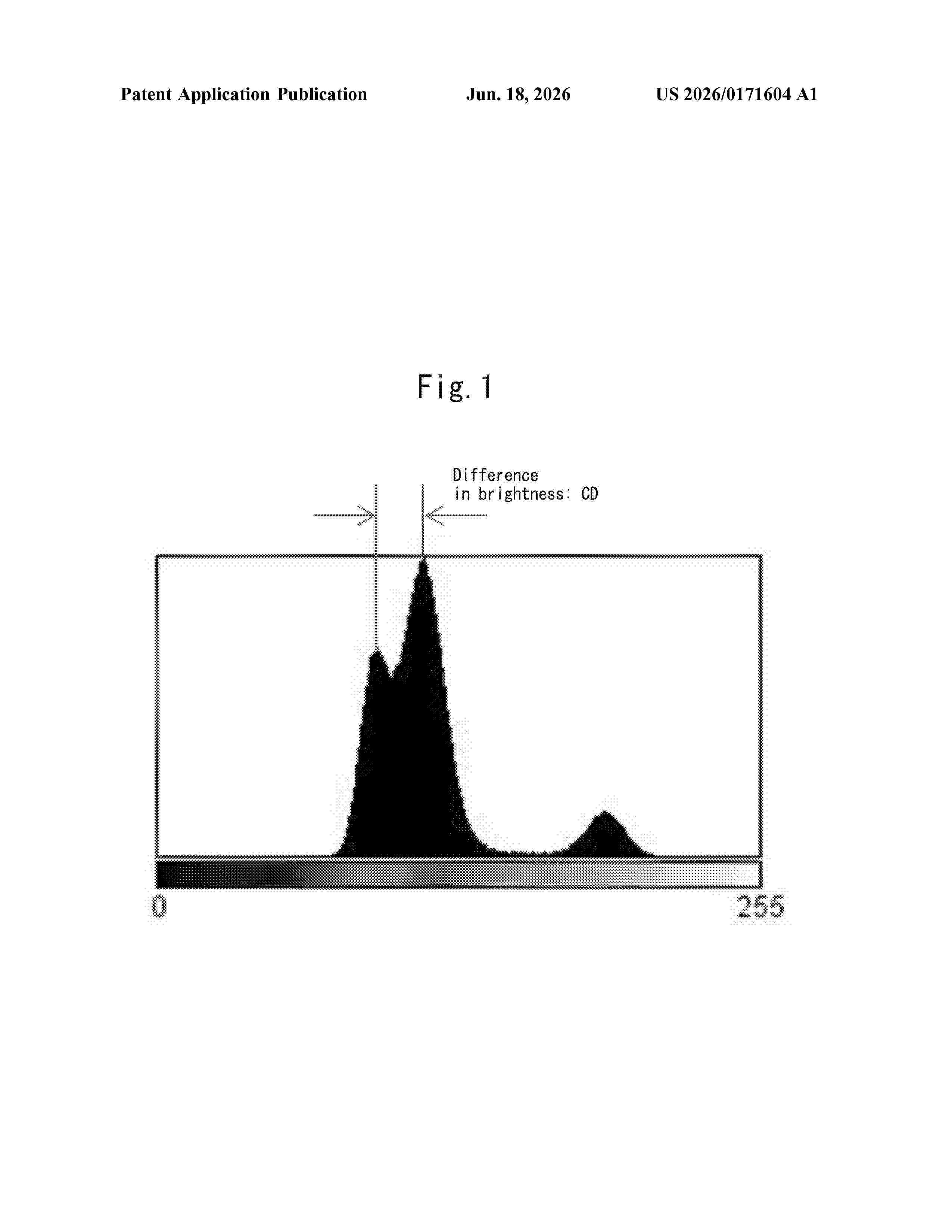
Resumen de: US20260171604A1
Provided are: a separator for an electric power storage device, the separator having high liquid absorption and high strength; and an electric power storage device in which the separator is used. The separator for an electric power storage device includes a microporous membrane (A) containing an inorganic filler and a polyolefin resin. The microporous membrane (A) has a MFR of 0.05-5 inclusive, includes not less than 20 mass % but less than 100 mass % of the organic filler, has an average pore diameter of 100-1500 nm inclusive for the pores in a cross-section ND-MD, and has an air permeability of 340 sec/100 mL or less.
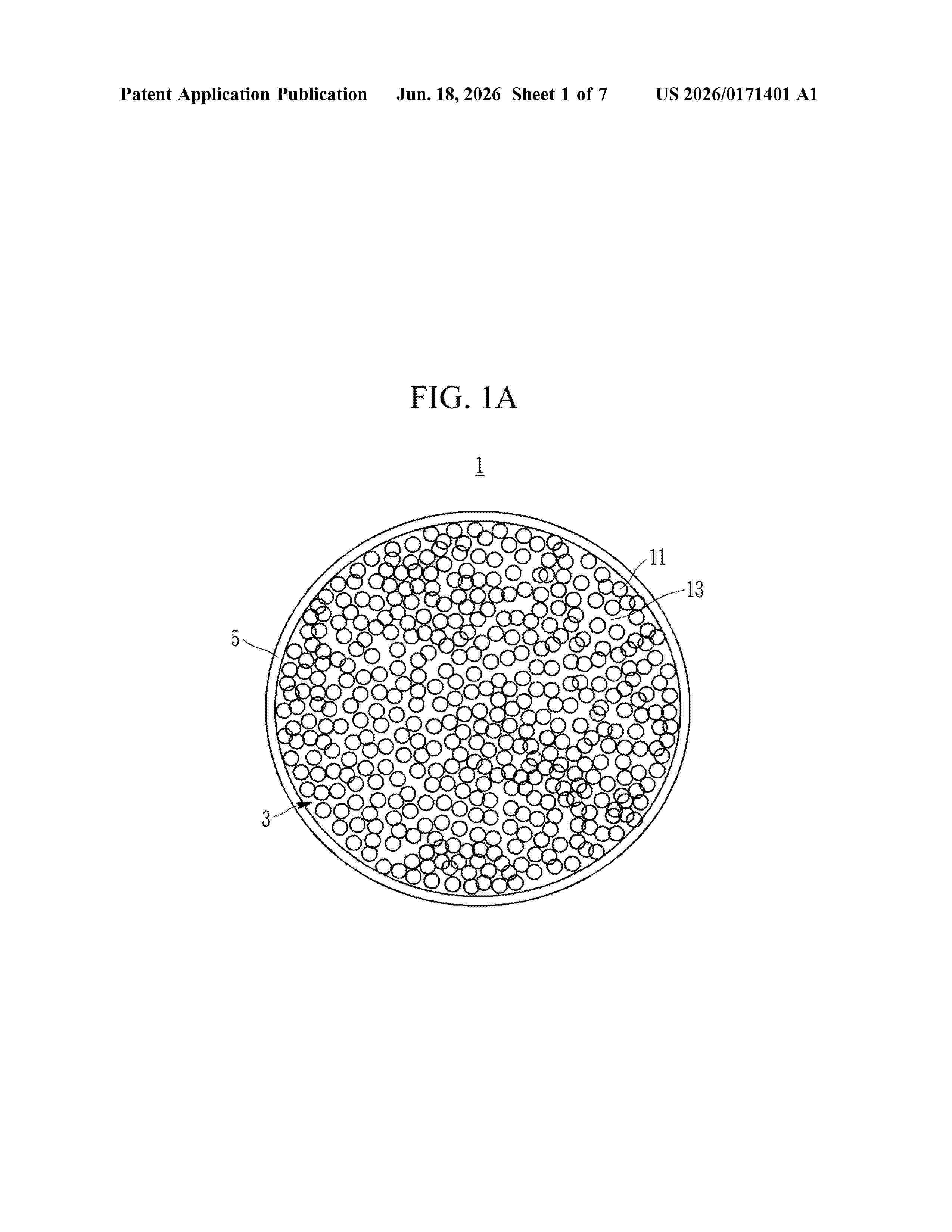
Resumen de: US20260171401A1
A negative active material composite includes a core and a coating layer surrounding the core. The core includes amorphous carbon and silicon nanoparticles, the coating layer includes amorphous carbon, and an adjacent distance between the silicon nanoparticles is less than or equal to about 100 nanometers.
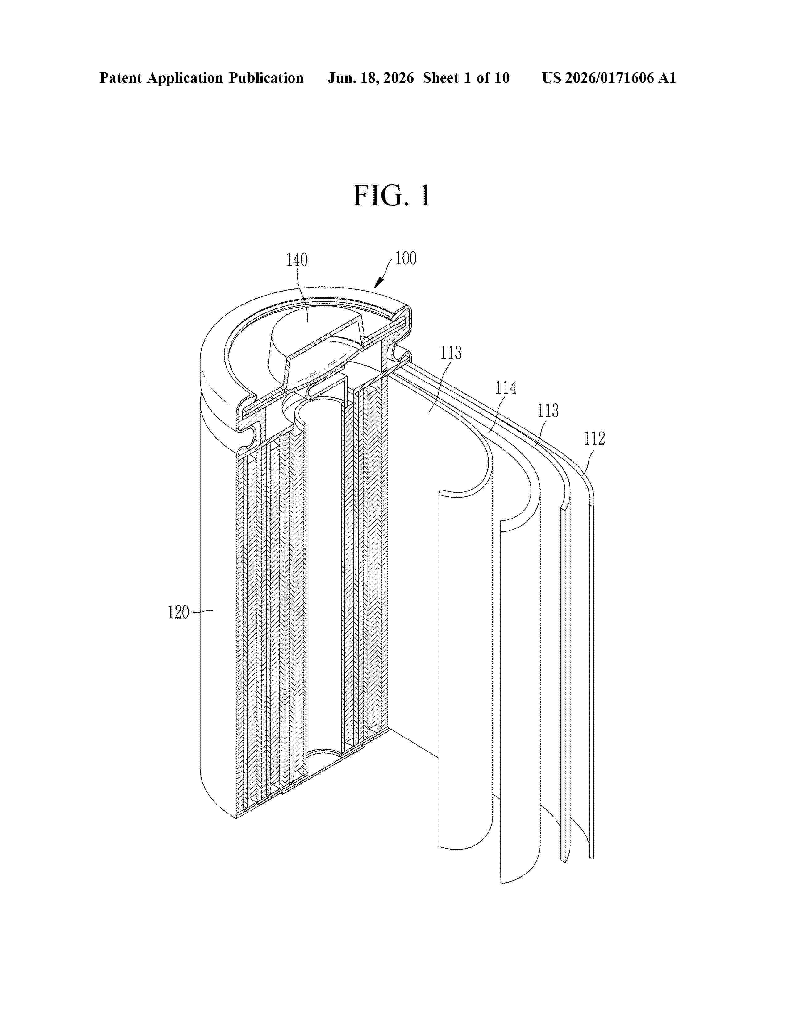
Resumen de: US20260171606A1
The present invention relates to a separator for a lithium secondary battery, and a lithium secondary battery including the same, the separator including a porous substrate and a coating layer located on at least one surface of the porous substrate, wherein the coating layer includes a heat-resistant binder including a (meth)acrylic copolymer including a first structural unit derived from (meth)acrylamide, a second structural unit derived from (meth)acrylonitrile, and a third structural unit derived from (meth)acrylaminosulfonic acid, a (meth)acrylaminosulfonate or a combination thereof; an adhesive binder having a core-shell structure; and inorganic particles, wherein the adhesive binder has an average particle diameter of 0.2 μm to 1.0 μm, and the inorganic particles have an average particle diameter of 0.2 μm to 1.0 μm.
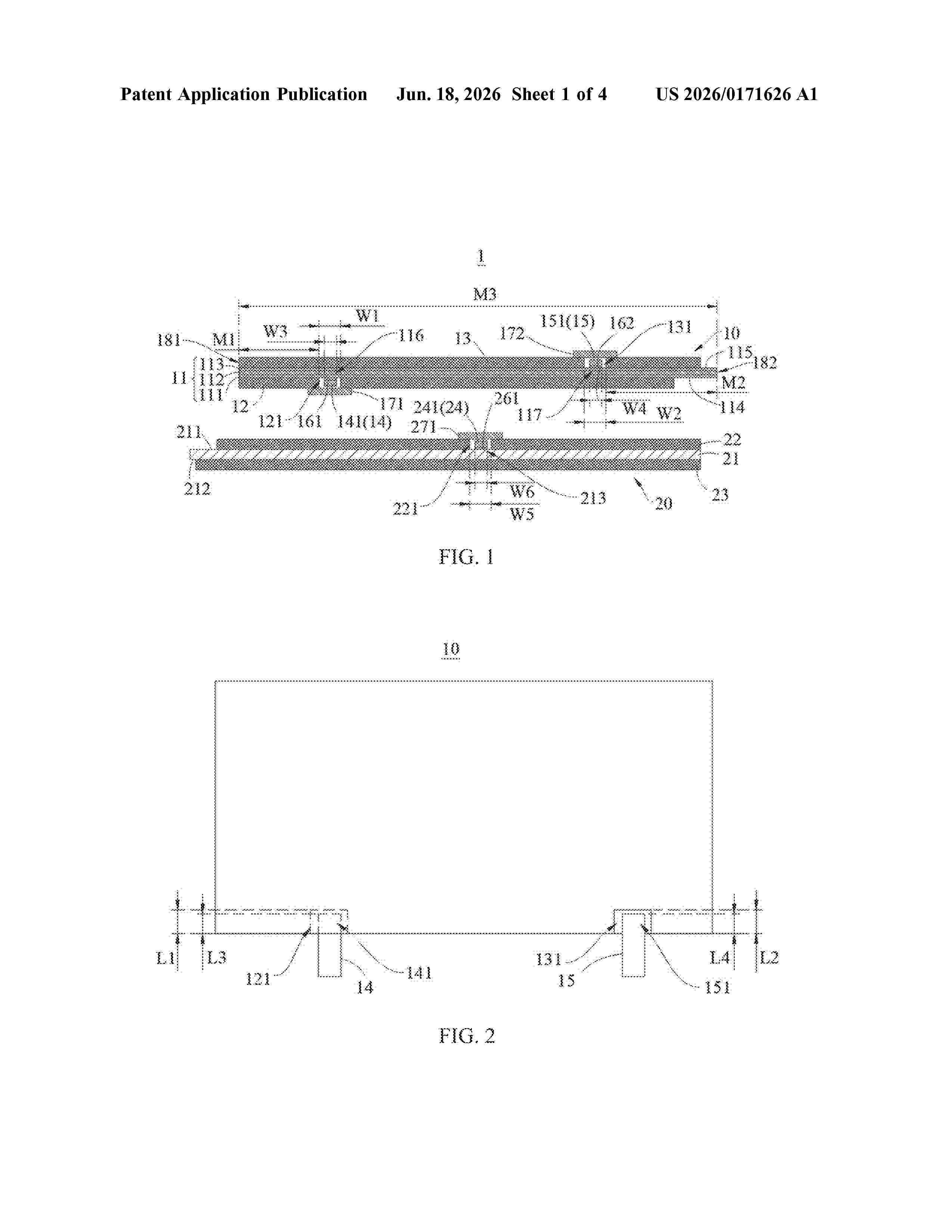
Resumen de: US20260171626A1
0000 An electrode assembly includes a first electrode plate and a second electrode plate of opposite polarities. A first current collector includes a first conductive layer, a first insulation layer, and a second conductive layer. A first active material layer is provided with a first groove. A first surface is exposed in the first groove. A second surface is covered by a second active material layer. The second active material layer is provided with a second groove. The first surface is covered by the first active material layer. The second surface is exposed in the second groove. A first tab is at least partially accommodated in the first groove, and is bonded to the first single-side blank foil region by a first adhesive layer. A second tab is at least partially accommodated in the second groove, and is bonded to the second single-side blank foil region by a second adhesive layer.
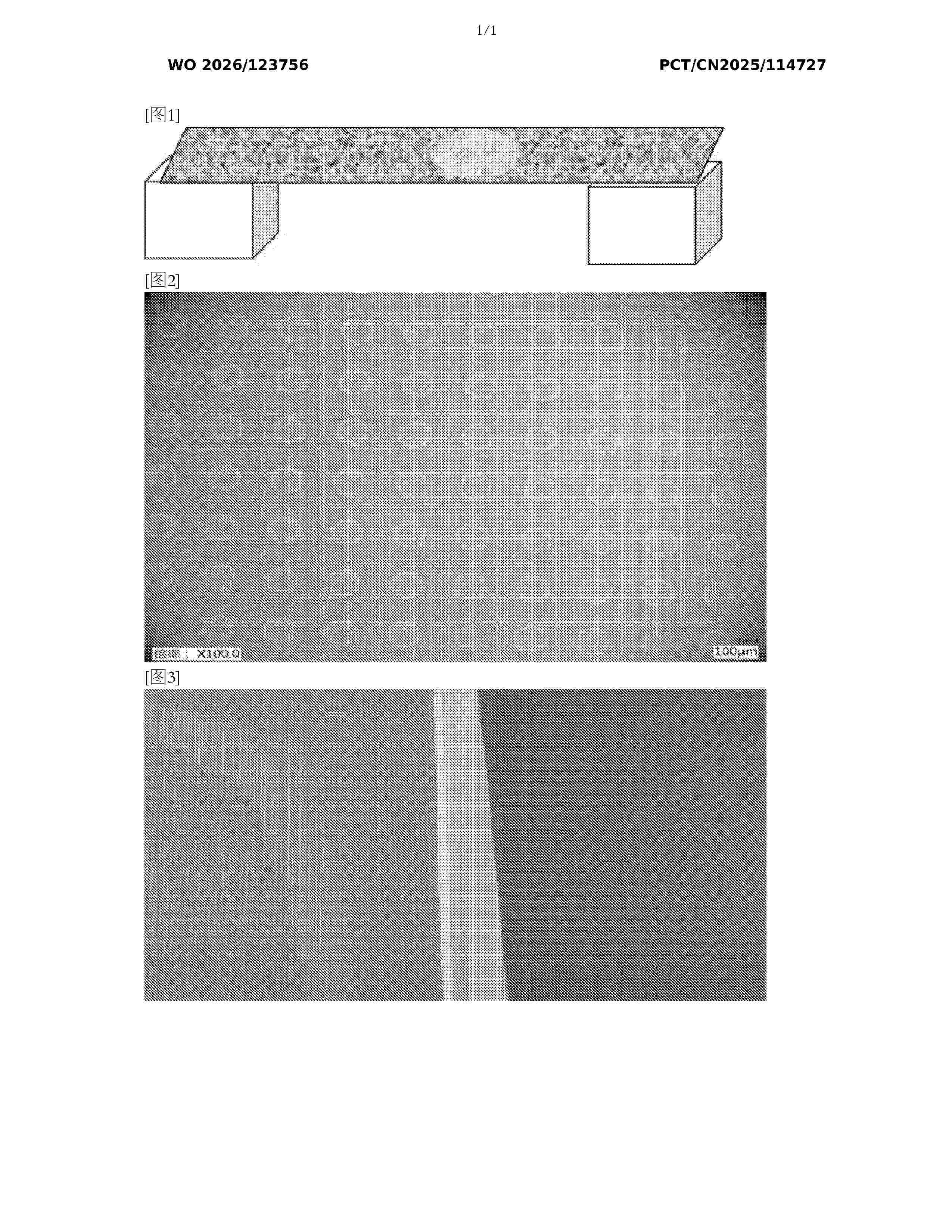
Resumen de: WO2026123756A1
A secondary battery and an electronic apparatus. A separator in the secondary battery comprises a base film layer. At least one surface of the base film layer is provided with a bonding layer, the bonding layer is composed of multiple bonding points, and the thickness of the bonding layer is 0.5 μm-5 μm. In the bonding layer, the longest diameter of a bonding point is 10 μm-400 μm, and the distance between adjacent bonding points is 100 μm-400 μm. An electrode sheet of the secondary battery comprises a current collector. At least one surface of the current collector is provided with an active layer, a partial region of a surface of the active layer is recessed inwards to form multiple scoring grooves, and the scoring grooves are arranged in the length direction of the electrode sheet. The width of each scoring groove is D1 mm, where 0.2≤D1≤1.5. The separator and the electrode sheet have good electrolyte transport capacity and storage capacity, and can enhance the cycle performance and fast charging performance of the secondary battery.
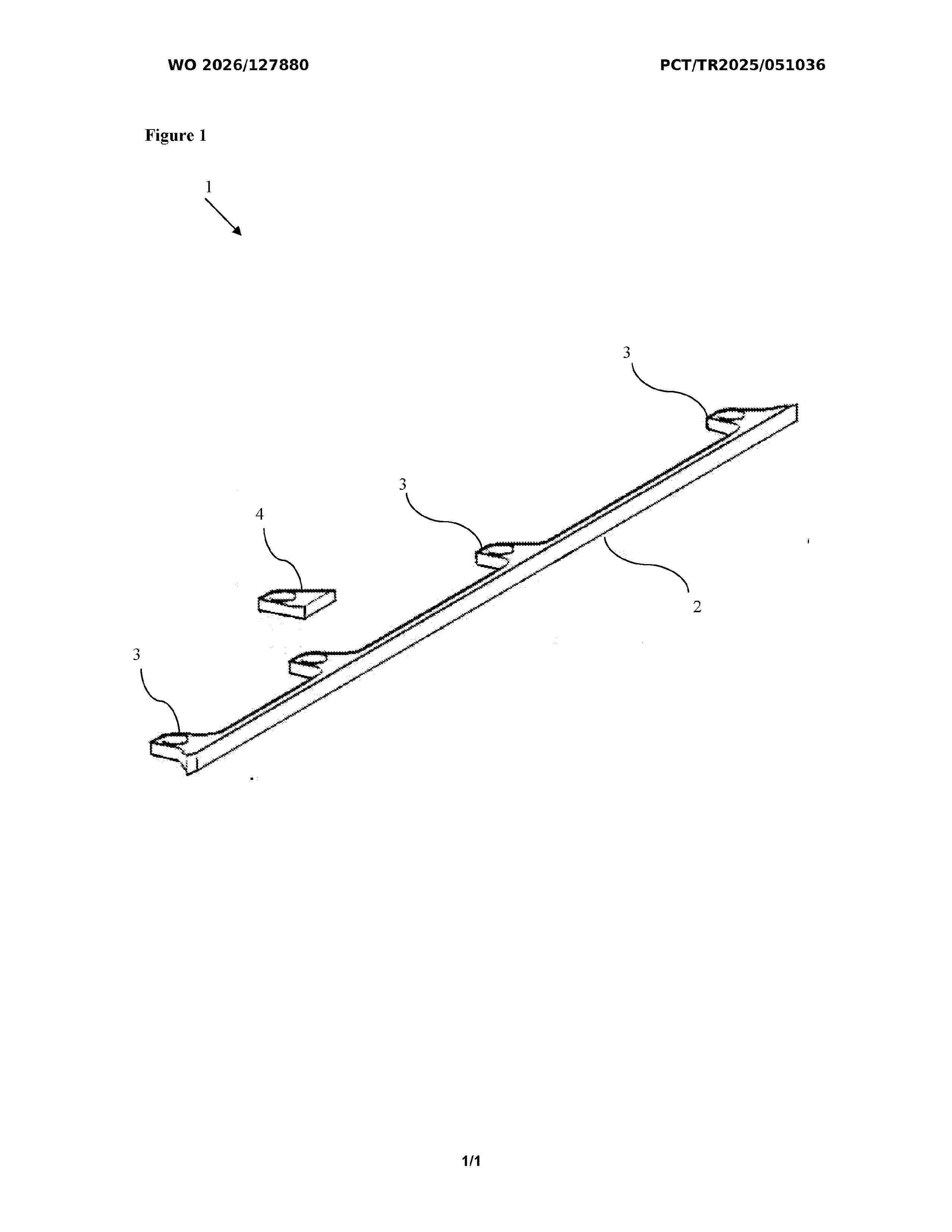
Resumen de: WO2026127880A1
The present invention relates to a battery module plate (1) wherein existing connection lugs (3) are supported by additional lugs (4) positioned thereon in order to withstand different dynamic loading conditions.
Nº publicación: WO2026127878A1 18/06/2026
Solicitante:
SIRO SILK ROAD TEMIZ ENERJI DEPOLAMA TEKNOLOJILERI SANAYI VE TICARET ANONIM SIRKETI [TR]
SIRO SILK ROAD TEMIZ ENERJI DEPOLAMA TEKNOLOJILERI SANAYI VE TICARET ANONIM SIRKETI
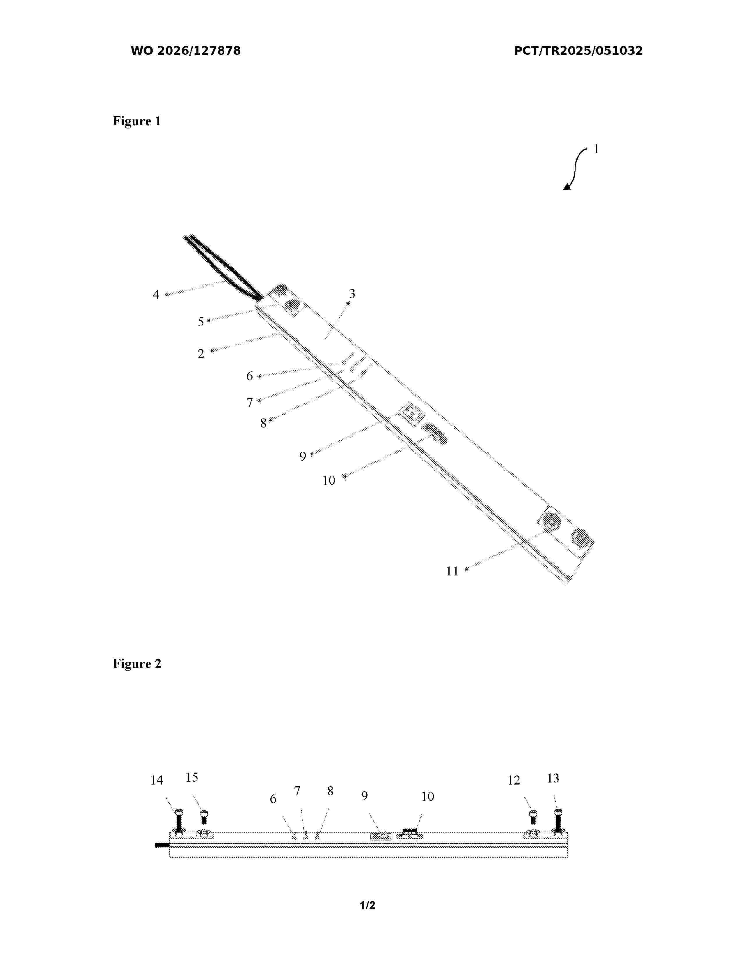
Resumen de: WO2026127878A1
The present invention relates to a system (1) which enables the gas formed in the module located in the electric vehicle battery packs to be discharged without spreading into the pack.
 BOPI
BOPI
 Sede Electrónica