Si deseas distinguir tus productos, servicios o ambos de los de otra empresa, es posible que necesites una marca o nombre comercial. Descubre qué son, en qué consiste su procedimiento de registro y qué implica.

Información sobre los plazos de presentación de solicitudes de transformación de marcas de la Unión Europea en marca nacional española. Más información


Si tienes un nuevo dispositivo, producto o procedimiento que resuelva un problema técnico o tenga una ventaja práctica, existen distintas formas de protegerlo en España y en otros países. Descubre cómo hacerlo.

¿Tu innovación reside en la estética, la ornamentación o la apariencia de tu producto? Protégela mediante un diseño industrial. Descubre qué derechos confiere el registro y cómo realizar la tramitación.

Las indicaciones geográficas protegen el nombre de un producto originario de una zona geográfica, a la cual le debe una determinada calidad, reputación u otra característica. Descubre qué son, en qué consiste su procedimiento de registro y qué beneficios conceden.

Las patentes publicadas en todo el mundo son una valiosa fuente de información científica, técnica y comercial.

Si eres emprendedor/a o una empresa y quieres potenciar y mejorar la rentabilidad de tu negocio protegiendo de forma adecuada los activos intangibles de tu organización, en este espacio encontrarás lo necesario.


 1603
resultados
1603
resultados
 Última actualización
24/06/2026 [07:18:00]
Última actualización
24/06/2026 [07:18:00]


 Resultados 75 a 100 de 1603

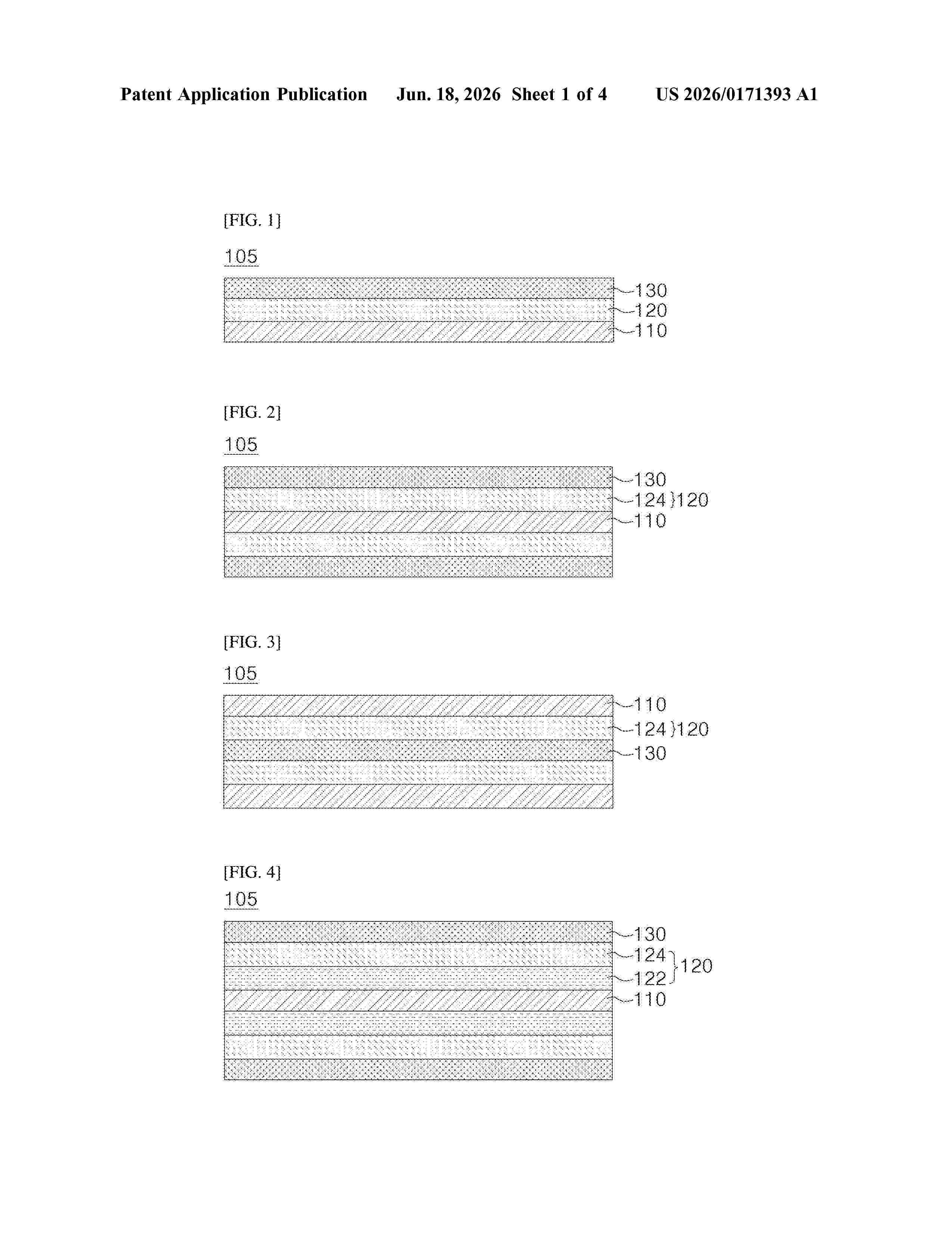
Resumen de: US20260171393A1
A cathode current collector for a lithium secondary battery according to embodiments of the present disclosure may include an aluminum layer, aluminum-copper alloy layers formed on the aluminum layer, and copper layers formed on the aluminum-copper alloy layer. Accordingly, even when a high-density cathode active material layer is formed on the cathode current collector, deformation or fracture of the cathode current collector may be prevented, thereby improving the cycle life of the secondary battery.

Resumen de: US20260171501A1
A secondary battery includes a positive electrode, a negative electrode, and an electrolytic solution. The electrolytic solution includes an anisole compound and a non-aqueous solvent. The anisole compound is represented by Formula (1). A molar ratio of the anisole compound to the non-aqueous solvent is 1.6 or greater.
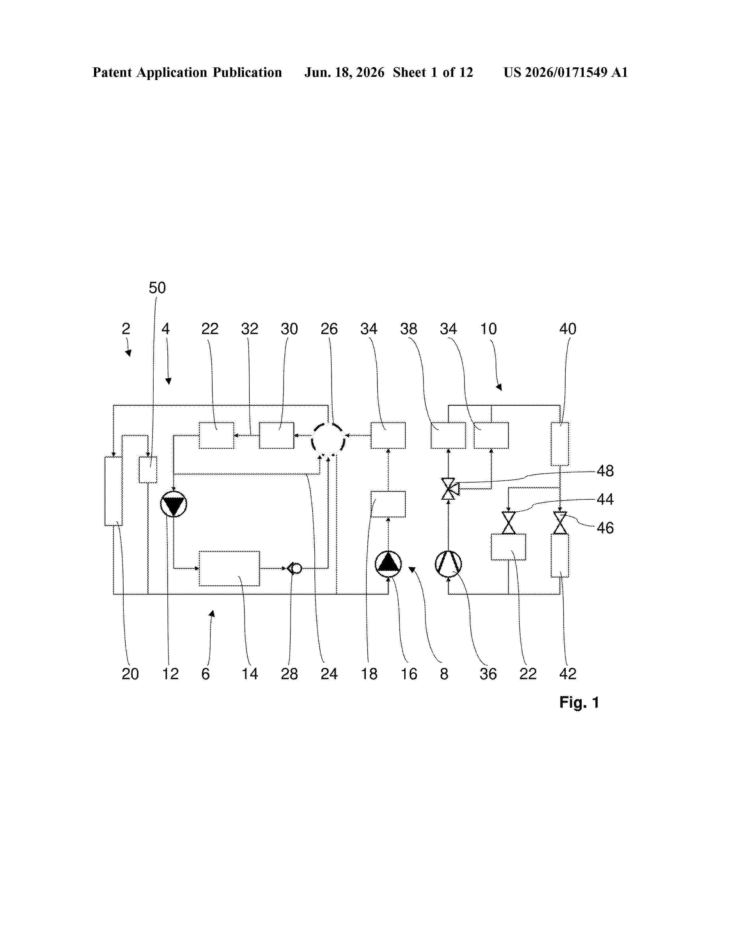
Resumen de: US20260171549A1
A coolant system for an electric vehicle for circulating a coolant, comprising a multiplicity of components through which the coolant can flow and can be connected to one another in terms of coolant flow via at least one valve and coolant lines. The multiplicity of components are arranged in a distributed manner in at least two coolant circuits of the coolant system that can be connected and disconnected by the at least one valve. A single expansion tank is arranged in only one of the coolant circuits. The coolant system is designed such that this coolant circuit is disconnected fluidically from at least one other coolant circuit of the at least two coolant circuits by the at least one valve, at least in one operating state of the coolant system, and, in this operating state, this other coolant circuit can be connected to the coolant circuit having the expansion tank.
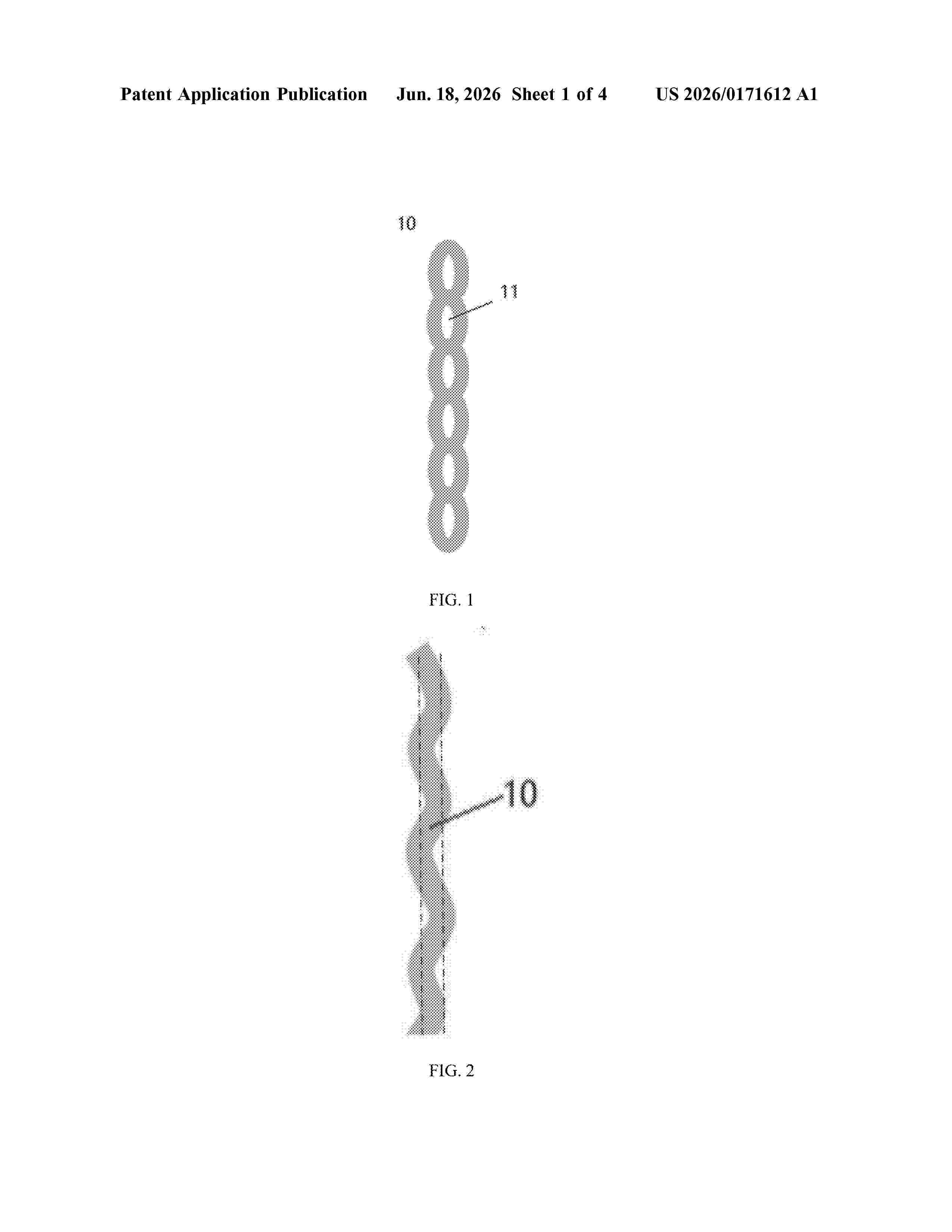
Resumen de: US20260171612A1
0000 This application provides a separator, an electrode assembly, a secondary battery, and an electric apparatus, where a resilience coefficient k of the separator ranges from 10% to 90%, where k=(H<0>−H<1>)/H<0>×100%, H<0 >represents an initial thickness of the separator at 25° C., and H<1 >represents a thickness of the separator having the initial thickness H<0 >after compressed at 25° C. with a load of 0.8 MPa for 60 seconds and then relaxed for 60 s after the load is removed. The separator of this application has excellent resilience performance.
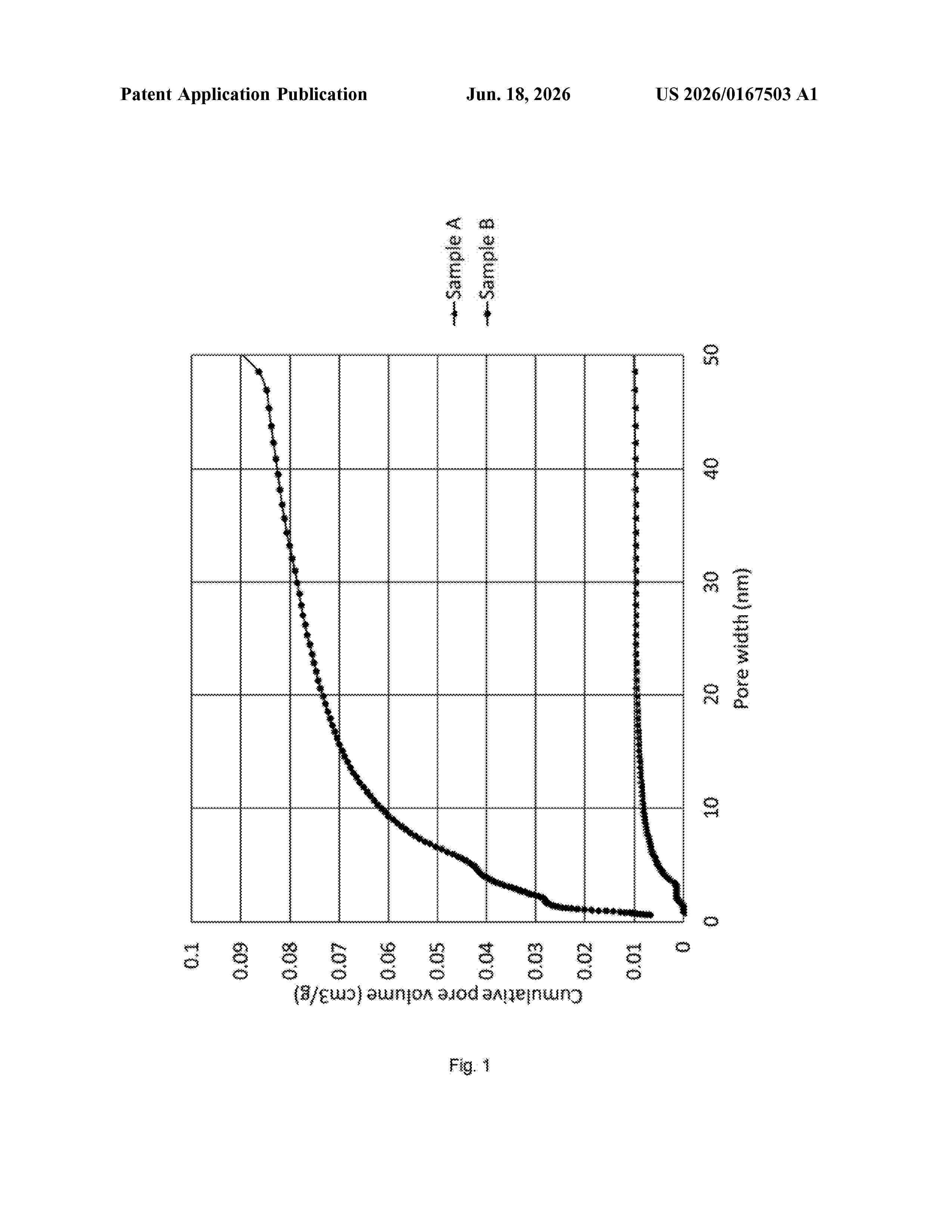
Resumen de: US20260167503A1
0000 The invention relates to a process for preparing composite particles. The process comprises the steps of providing a plurality of porous particles comprising micropores and/or mesopores; contacting the porous particles with a silicon-containing precursor at a temperature effective to cause deposition of a plurality of silicon domains in the pores of the porous particles; subjecting the particles to heat treatment at a temperature of at least 400° C. and in the presence of an inert gas; and contacting the particles with a silicon-containing precursor at a temperature effective to cause deposition of further silicon domains in the pores of the porous particles.
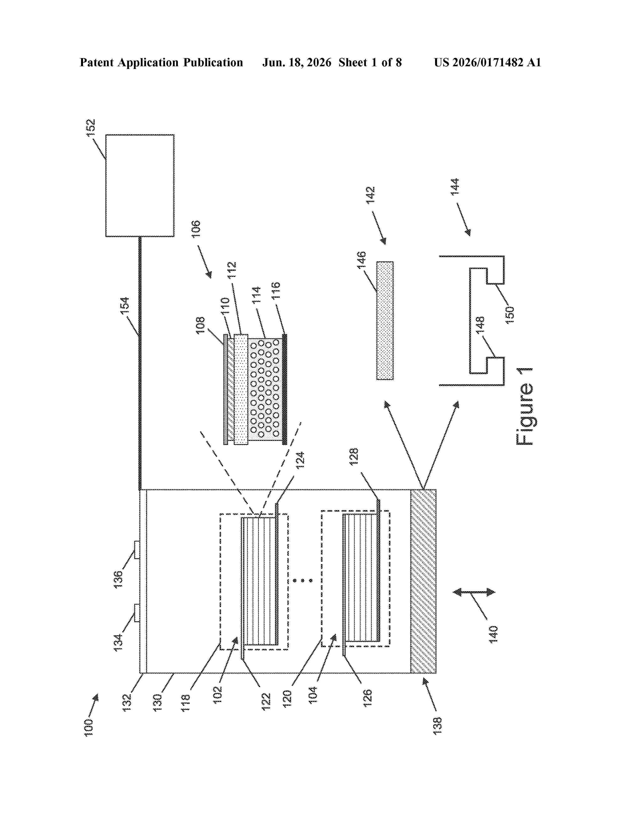
Resumen de: US20260171482A1
A battery unit comprises an arrangement of a plurality of stacked battery cells with individual battery cells including a number of discrete layers. The layers of the battery cells can include a solid-state separator layer. Dimensions of the battery cells are configured to minimize stress placed on one or more layers of the battery cells and to provide flexibility in the arrangements of battery cells to provide voltages and/or currents based on a load being driven by the battery cells.
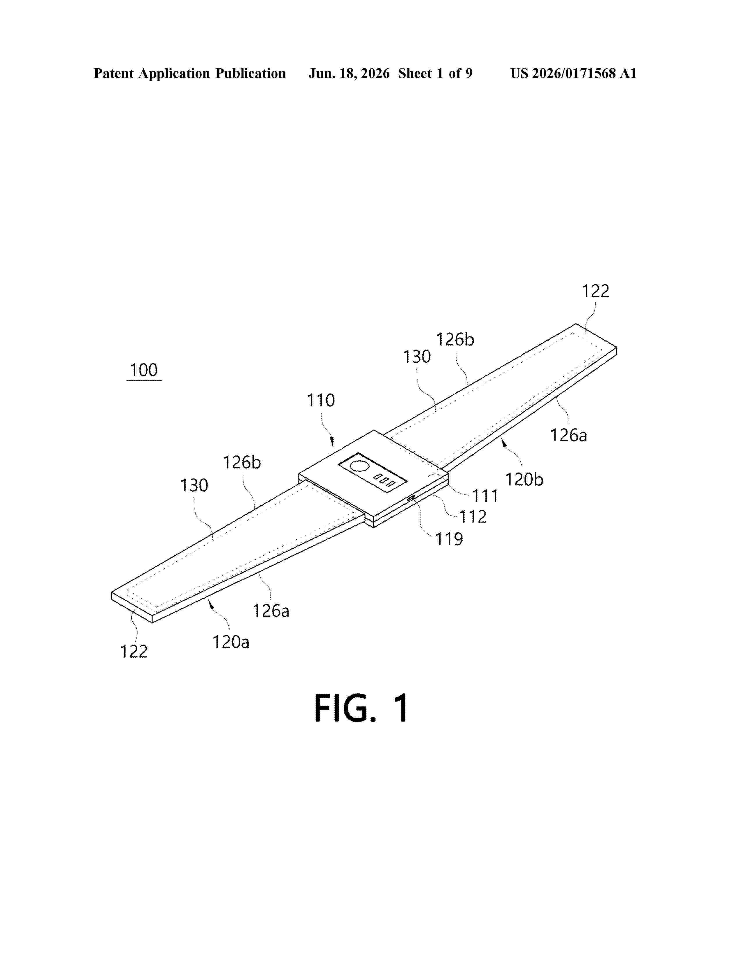
Resumen de: US20260171568A1
0000 An auxiliary battery is provided. An auxiliary battery, according to one embodiment of the present invention, comprises: a main body comprising a case, a circuit board built into the case, and charge and discharge ports mounted on the circuit board; and a battery unit which comprises a plate-shaped flexible battery having a predetermined area and a soft cover member covering the flexible battery, and is coupled to the main body such that the flexible battery is electrically connected to the circuit board, wherein the cover member may be formed of a flexible and waterproof material.
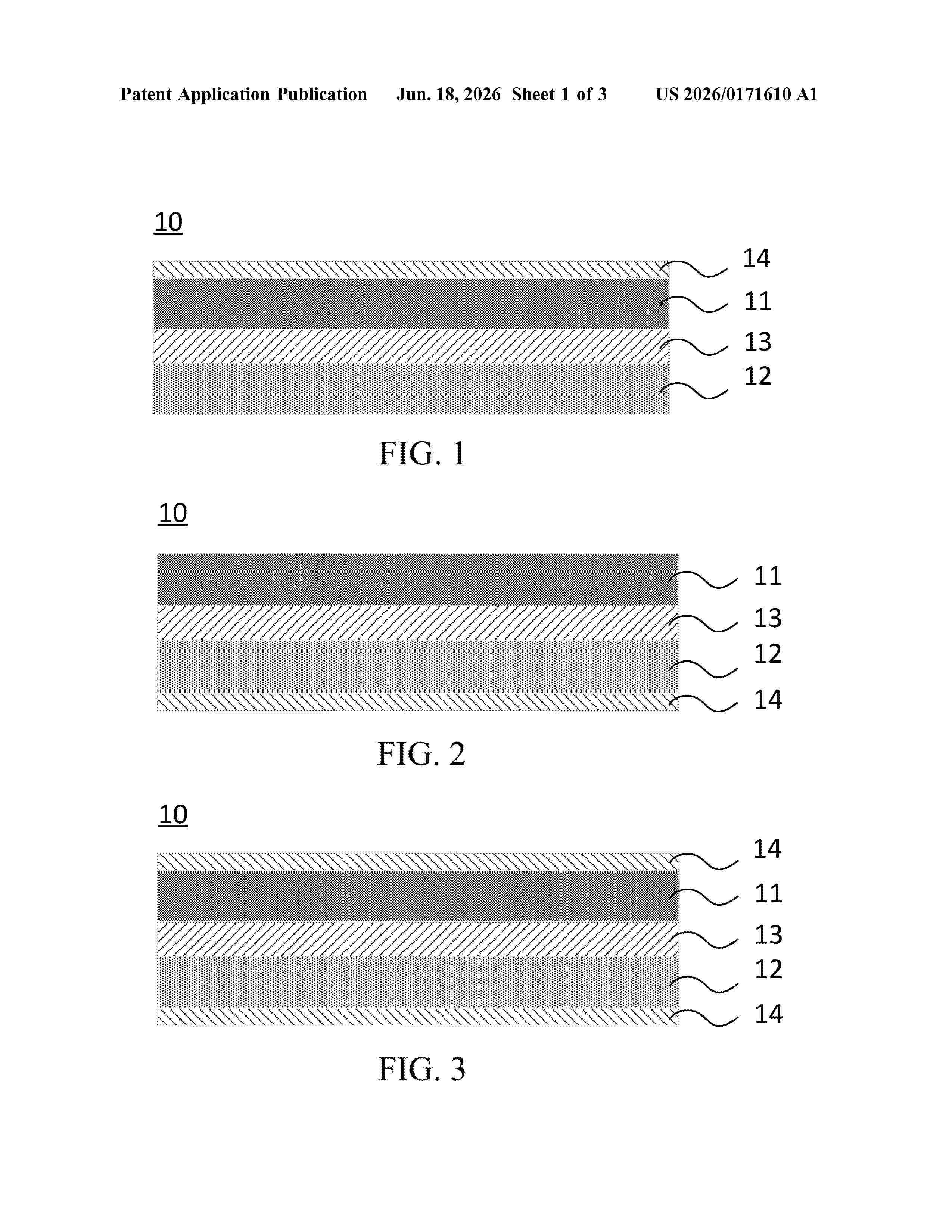
Resumen de: US20260171610A1
Provided in the present application are a separator and a preparation method therefor, a secondary battery, and an electric device. The separator includes a first substrate, a second substrate, a first bonding layer, and a second bonding layer, where the first bonding layer is located between the first substrate and the second substrate, and the first bonding layer includes a first binder; and the second bonding layer is located on one side of the first substrate and/or the second substrate facing away from the first bonding layer, and the second bonding layer includes a second binder. If the thickness of the first bonding layer is denoted as T1 and the thickness of the second bonding layer is denoted as T2, the separator satisfies: T1/T2>1.
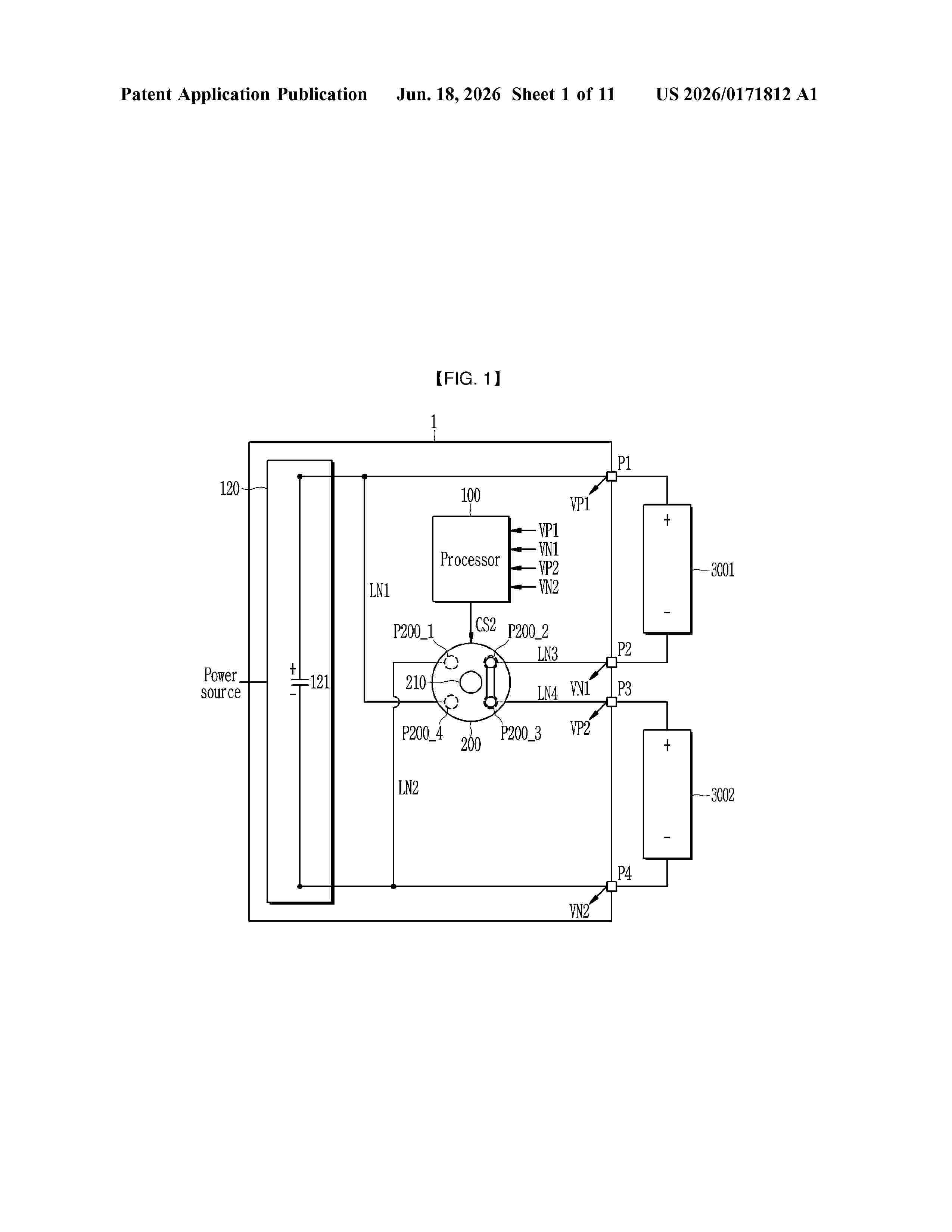
Resumen de: US20260171812A1
The present disclosure relates to a battery charging system and a battery charging method, and the battery charging system is connected to a respective positive electrode battery terminal and negative electrode battery terminal of each battery of a plurality of batteries including a first battery and a second battery, and includes a charger configured to supply power, a bypass configured to rotate about a central shaft and configured to provide a power route that connects at least one of the first and second batteries to a respective positive electrode charger terminal and negative electrode charger terminal of the charger, and a processor configured to monitor a respective end voltage between the respective positive electrode battery terminal and negative electrode battery terminal of each battery of the first and second batteries and control a rotation direction and a rotation angle of the bypass.
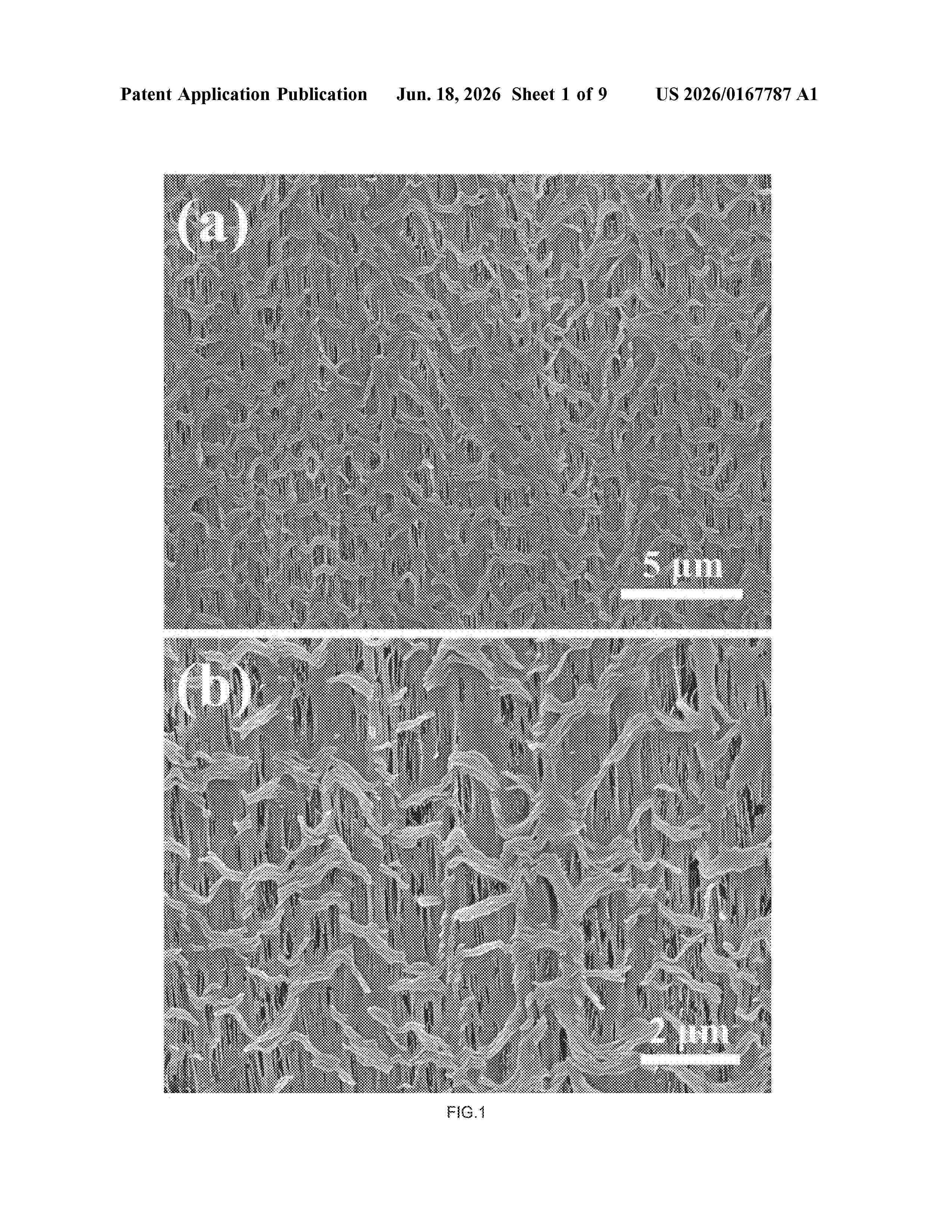
Resumen de: US20260167787A1
0000 Disclosed herein provides the porous polyolefin composites, which comprise the polyolefin polymer as the matrix and embedded fillers with high aspect ratio as the reinforcing element and are mainly featured by the enhanced mechanical properties in biaxial direction. These said composites can be used as filtering semi-permeable membranes in filtration/purification of air, water or other liquids, or can be used as separators in energy industries.
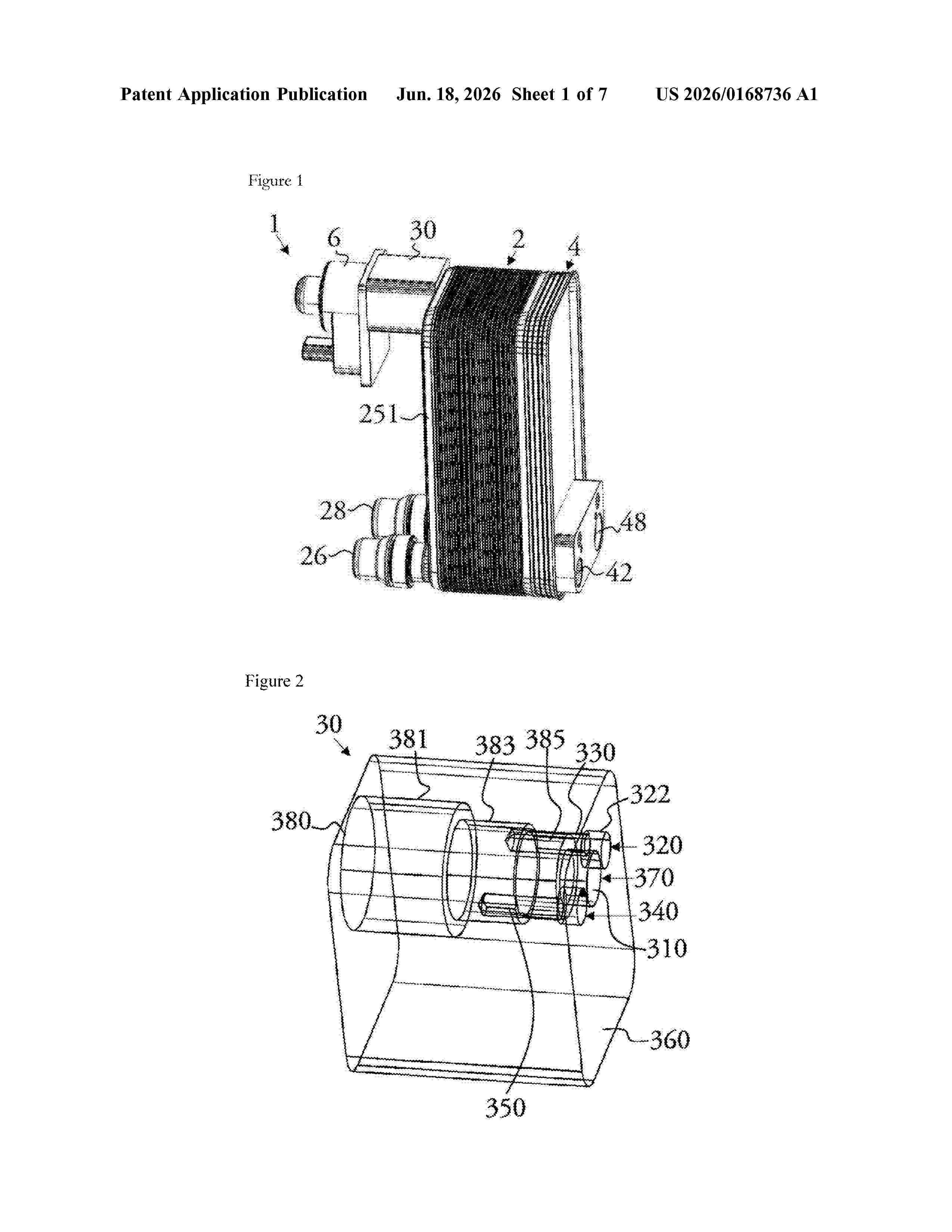
Resumen de: US20260168736A1
A connection block is configured to sealingly connect an expansion member to a heat exchanger. The connection block includes a refrigerant inlet, first and second refrigerant outlets, and receiving means for receiving the expansion member. The refrigerant inlet and the first and second refrigerant outlets are arranged on a contact surface with the heat exchanger. The receiving means are connected by a branch of the connection block to the refrigerant inlet, by a first passage of the connection block to the first refrigerant outlet and by a second passage of the connection block to the second refrigerant outlet.
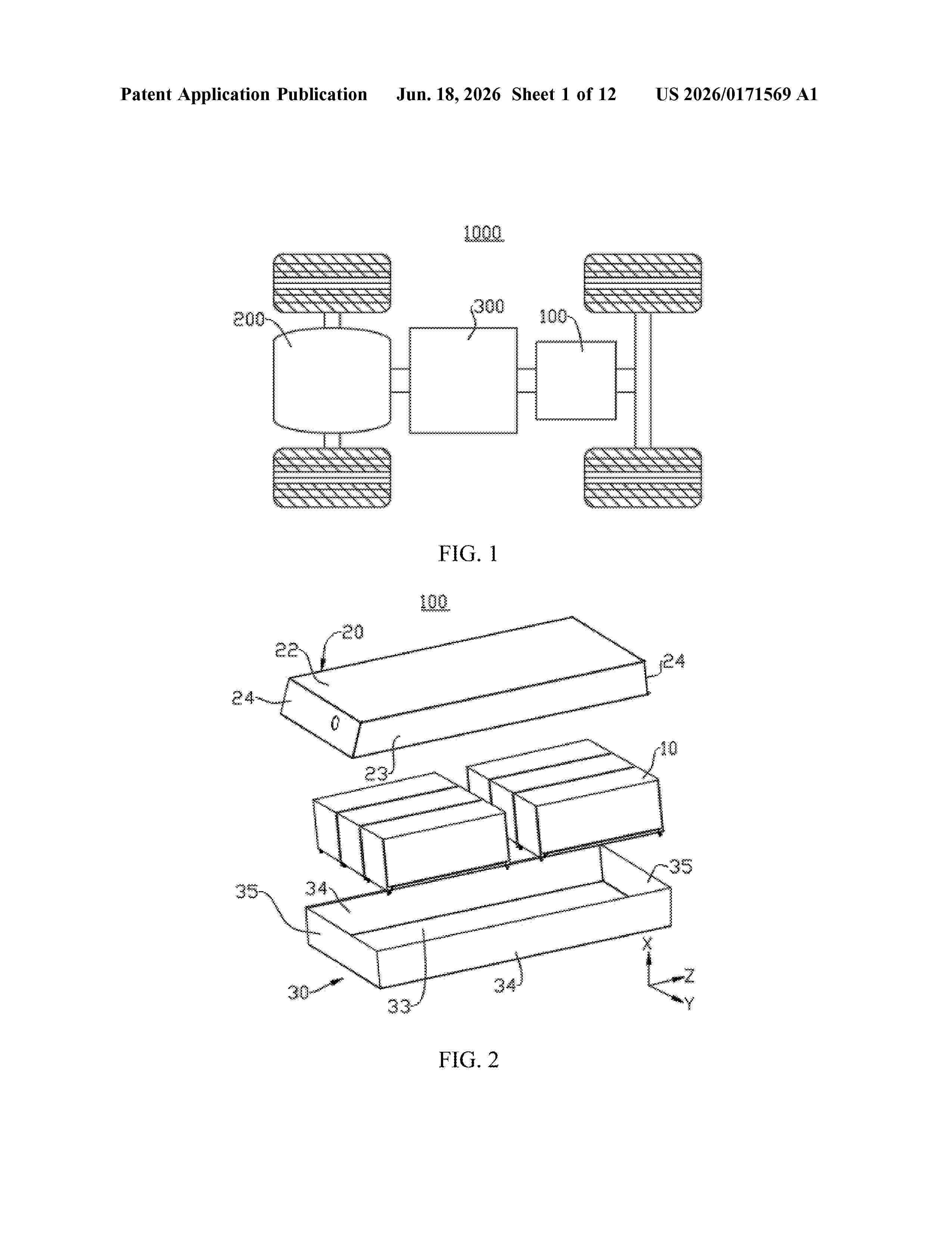
Resumen de: US20260171569A1
A battery and an electric device. The battery includes a battery cell, a first housing, and a second housing. The first housing includes a first sealing surface; and the second housing includes a first surface and a second sealing surface, where the first surface is configured to support the battery cell. The first housing and the second housing jointly enclose a closed space for accommodating the battery cell. The first sealing surface cooperates with the second sealing surface to seal the closed space. The first sealing surface intersects with the first surface, and the second sealing surface intersects with the first surface, reducing the space occupied by the first sealing surface and the second sealing surface in a direction parallel to the first surface and intersecting with the first sealing surface and the second sealing surface.
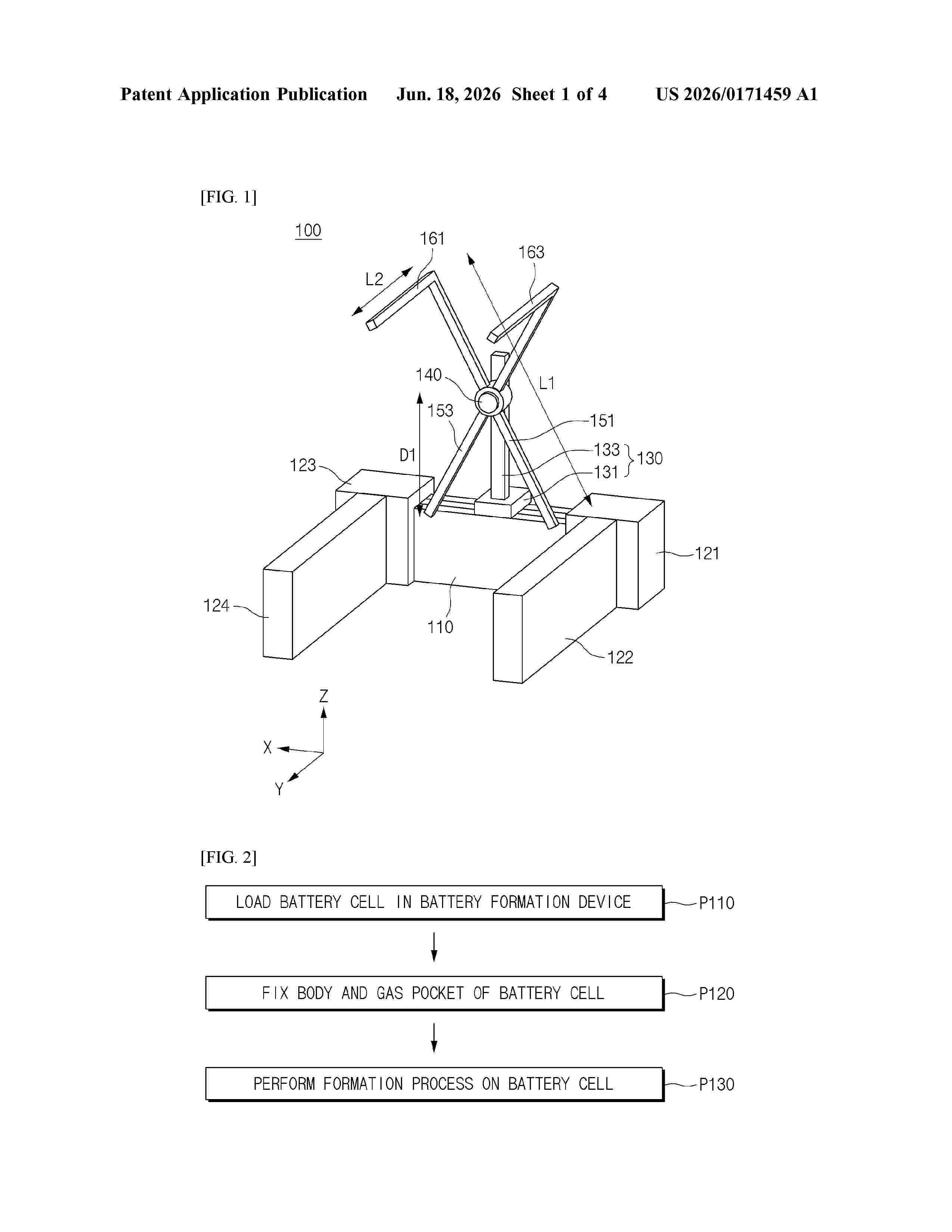
Resumen de: US20260171459A1
0000 A battery formation device is provided. The battery formation device includes a horizontal frame, first and second clamp holders configured to be moved along the horizontal frame, a vertical frame on the horizontal frame, a drive shaft coupled to the vertical frame, first and second arms coupled to the drive shaft, a first guide connected to the first arm, and a second guide connected to the second arm, wherein the first and second guides are configured to fix a gas pocket of a battery cell, and the battery formation device is capable of preventing damage to the gas pocket and the battery cell during unloading of the battery cell.
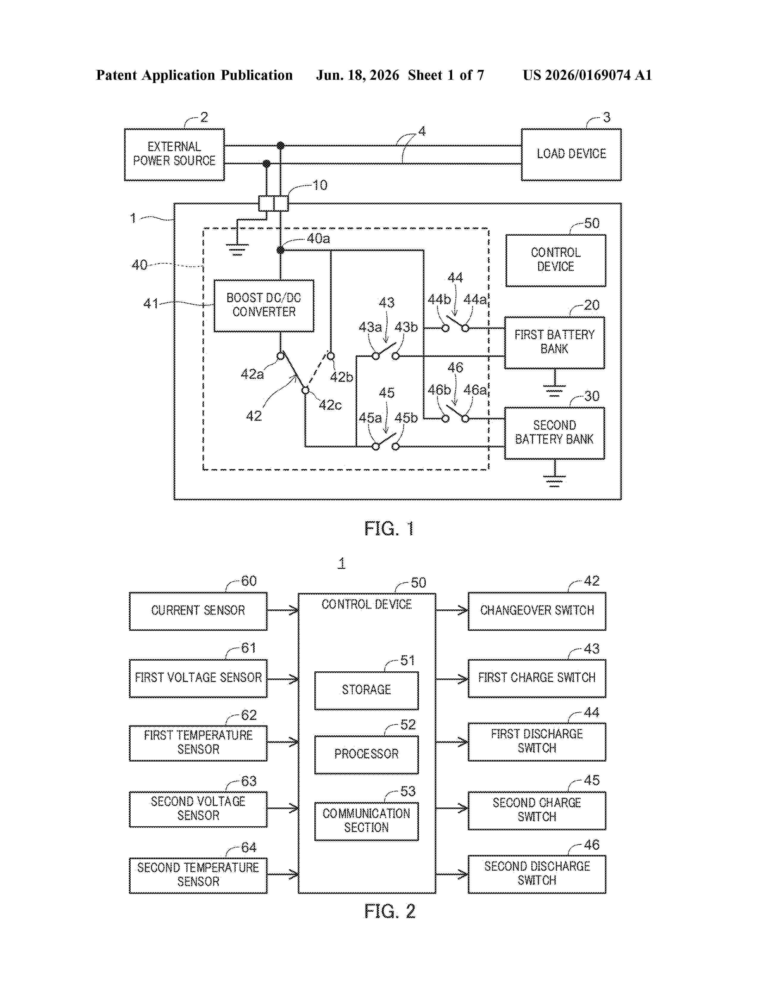
Resumen de: US20260169074A1
The purpose of the present invention is to allow users to sooner understand a more accurate time required in order for charging to complete. This charging control device comprises: a processing unit that, during charging of a power storage device, corrects a calculated value of remaining charging time calculated at the start of charging of the power storage device, and, at the start of charging, acquires information indicating a correction timing at which the calculated value of the remaining charging time is corrected; and a reporting unit that reports the correction timing at the start of charging and reports the correction value of the calculated value of the remaining charging time during charging.
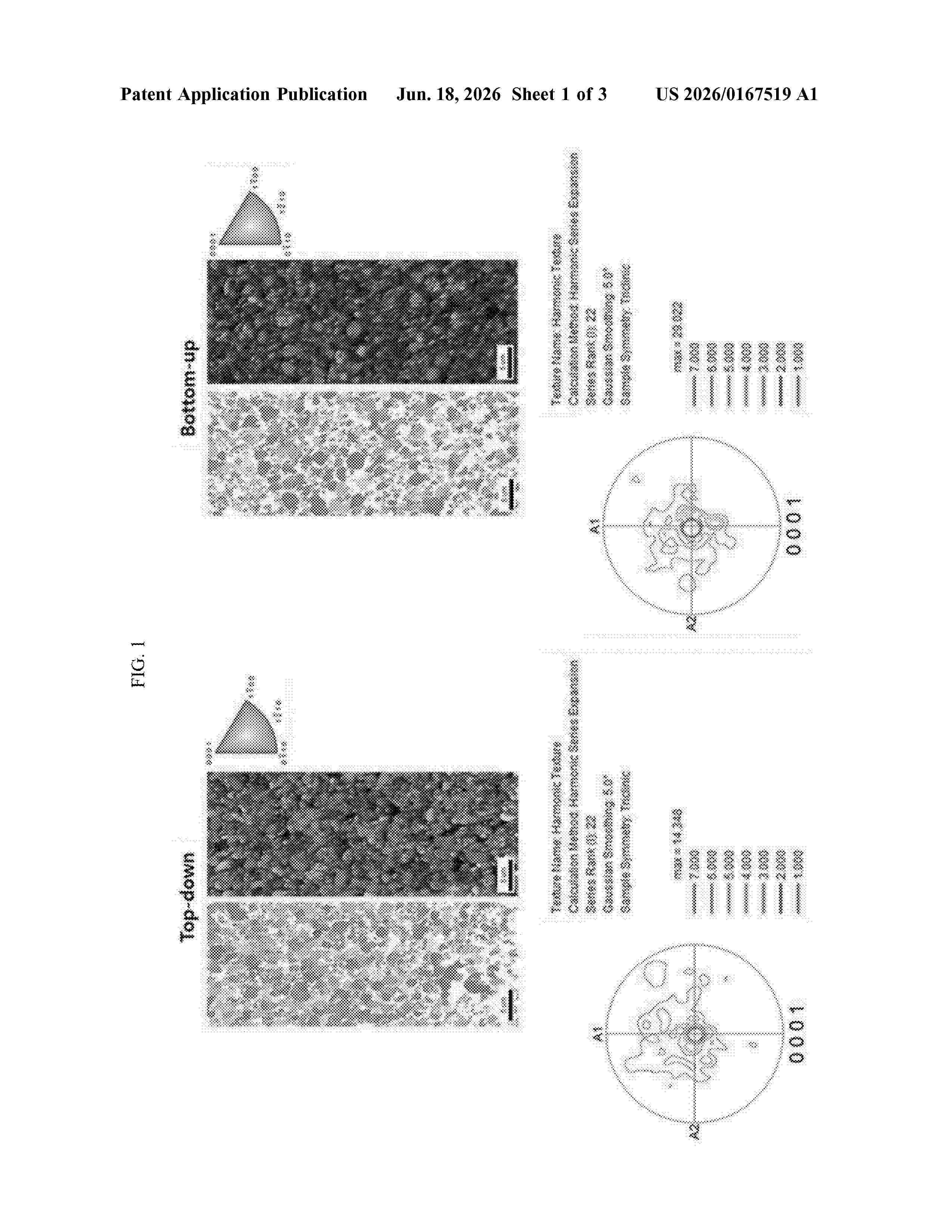
Resumen de: US20260167519A1
The present invention relates to a positive electrode active material for a lithium secondary battery, comprising a lithium transition metal oxide containing nickel (Ni), wherein the lithium transition metal oxide is in form of a single particle, has an average particle diameter (D50) ranging from 2 μm to 4 μm, and exhibits a maximum pole density value of 20 or less at the (001) plane as determined by Electron Back Scatter Diffraction (EBSD) analysis of a pole figure diagram.
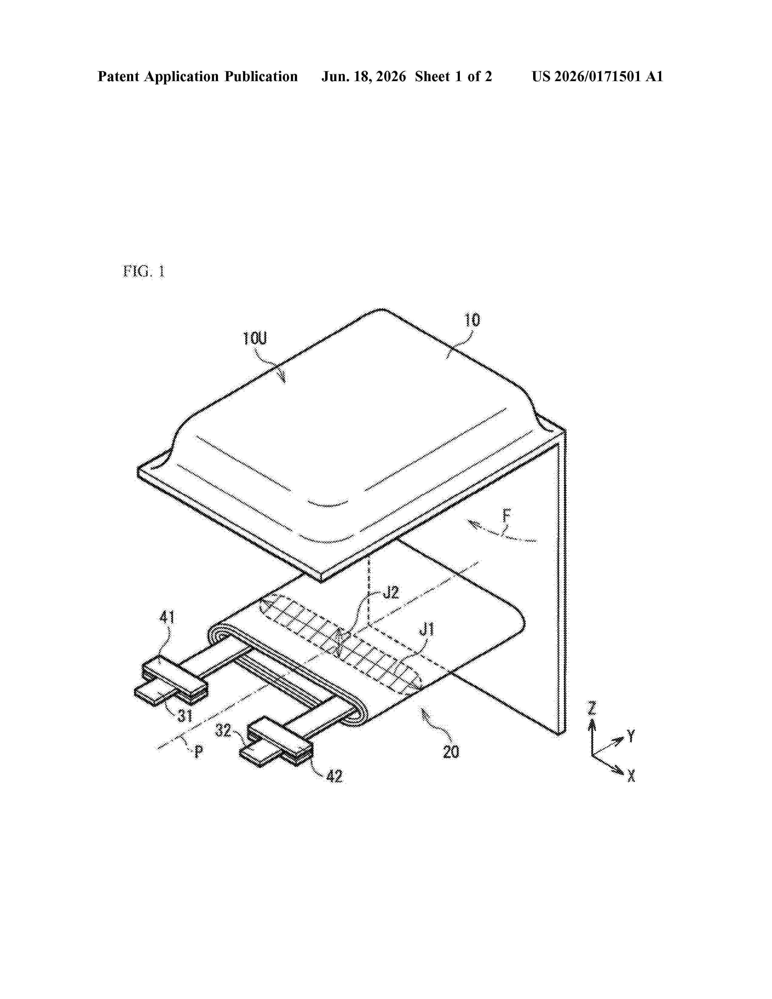
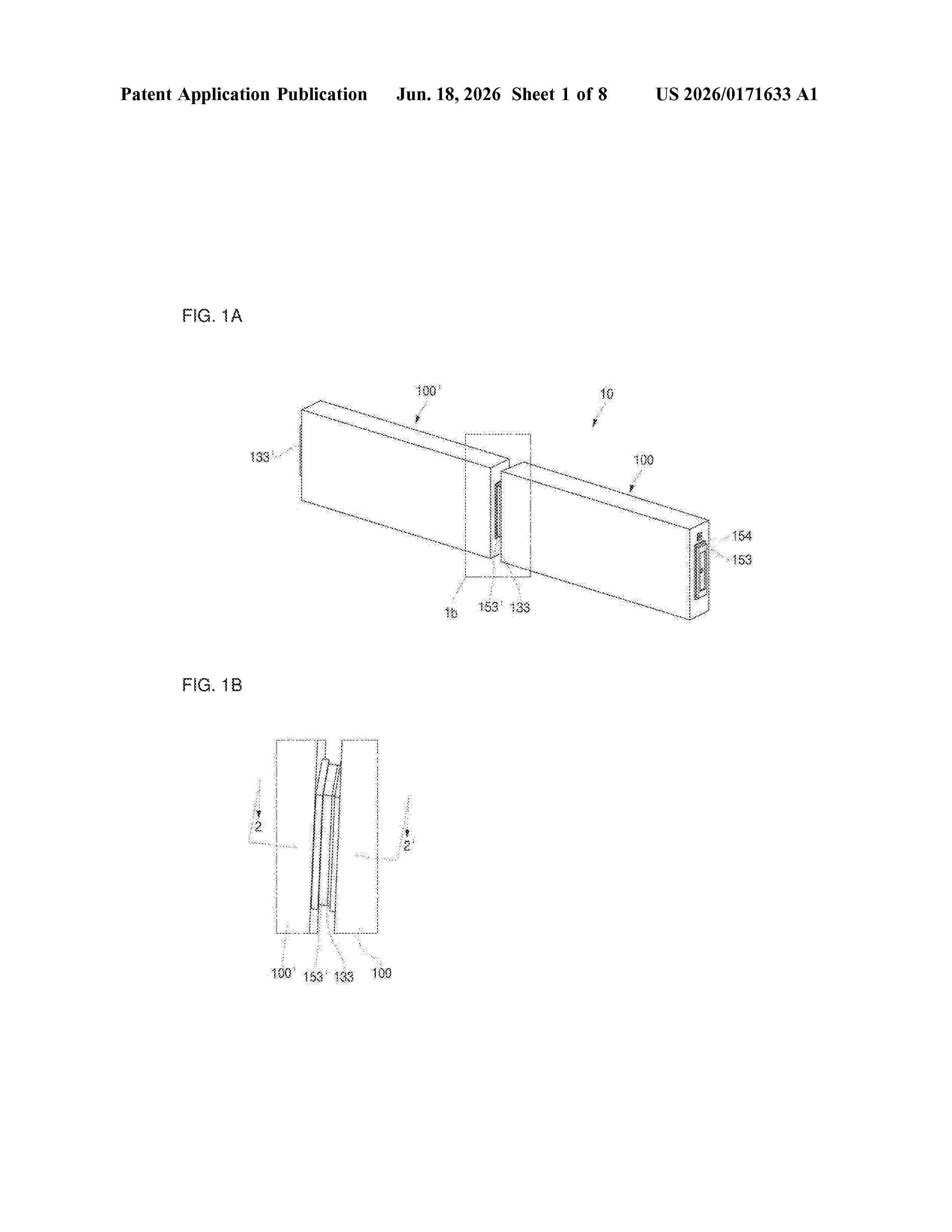
Resumen de: US20260171633A1
The present invention relates to a battery module in which terminals of two secondary batteries are directly coupled by welding, and which thus does not require a separate component for electrical connection and can reduce electrical contact resistance. Disclosed as an embodiment of the present invention is a battery module comprising a first secondary battery and a second secondary battery having the same structure as the first secondary battery, the first secondary battery comprising: an electrode assembly having a first electrode tab and a second electrode tab respectively exposed on both sides thereof; a case accommodating the electrode assembly and having two open sides; a first cap plate sealing one open side of the case; a first terminal electrically connected to the first electrode tab and exposed to the outside of the first cap plate; a second cap plate sealing the other open side of the case; and a second terminal electrically connected to the second electrode tab and exposed to the outside of the second cap plate, wherein a first protrusion portion protruding outwardly from the first terminal of the first secondary battery is coupled to and connected in series, by welding, with a second recessed portion recessed into the second terminal of the second secondary battery.
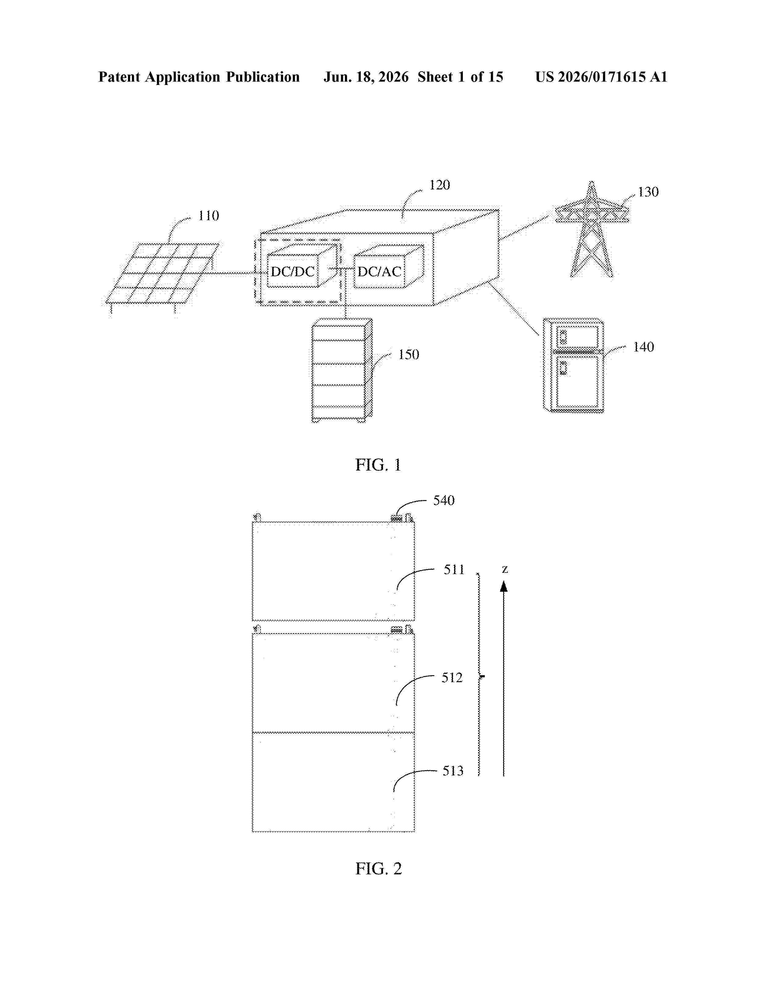
Resumen de: US20260171615A1
A battery pack, an energy storage apparatus, and an energy storage system are provided. The energy storage apparatus includes a plurality of stacked battery packs, each battery pack including a plurality of battery cells. In two contact surfaces of two adjacent battery packs, a protective part and a first connector are disposed on one of the contact surfaces in a protruding manner, and a groove and a second connector are disposed on the other of the contact surfaces. The second connector is located in the groove, the protective part is connected to the groove, and the first connector is connected to the second connector. The energy storage apparatus can implement accurate alignment between the battery packs, thereby greatly reducing an assembly procedure and an assembly time for mounting the energy storage apparatus and improving assembly efficiency of the energy storage apparatus.
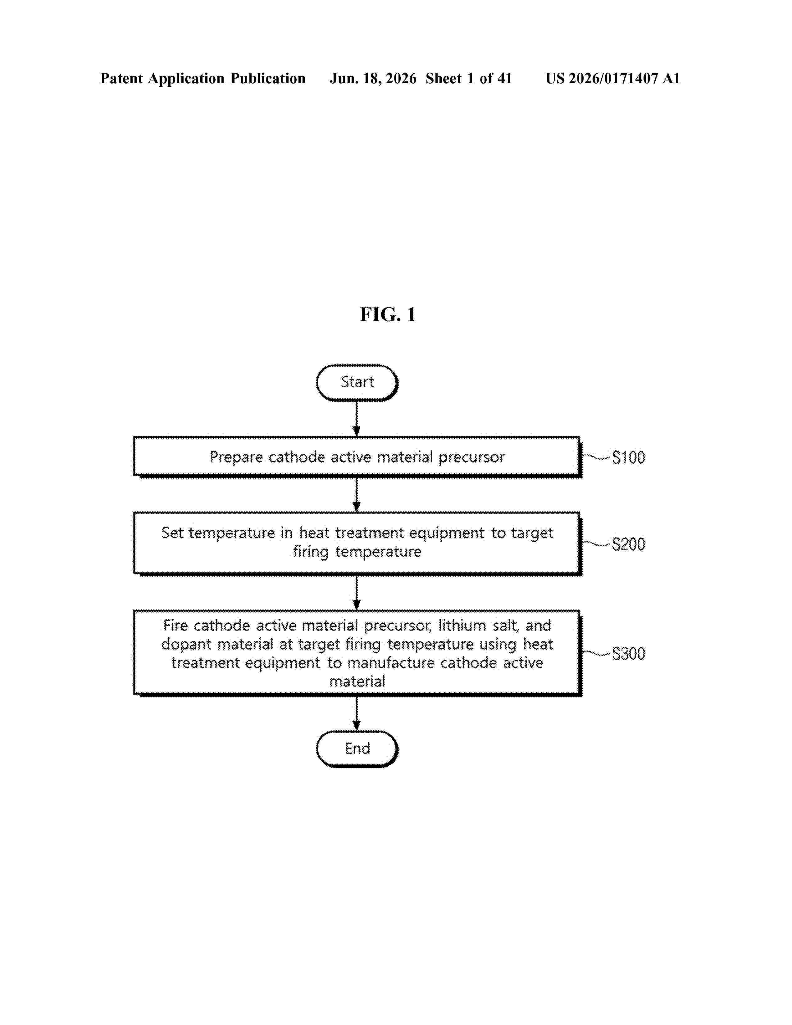
Resumen de: US20260171407A1
0000 A method for manufacturing a cathode active material comprises: preparing a cathode active material precursor; setting the temperature in heat treatment equipment to a target firing temperature; and firing the cathode active material precursor, a lithium salt, and a dopant material at the target firing temperature using the heat treatment equipment to manufacture the cathode active material, wherein the target firing temperature is controlled according to the dopant material. The setting the temperature in the heat treatment equipment to a target firing temperature includes: obtaining the difference value between a set firing temperature of the heat treatment equipment and the actual firing temperature in the heat treatment equipment; constructing a DB on the basis of the difference value; and using the DB to set the set firing temperature of the heat treatment equipment so that the target firing temperature matches the actual firing temperature in the heat treatment equipment.
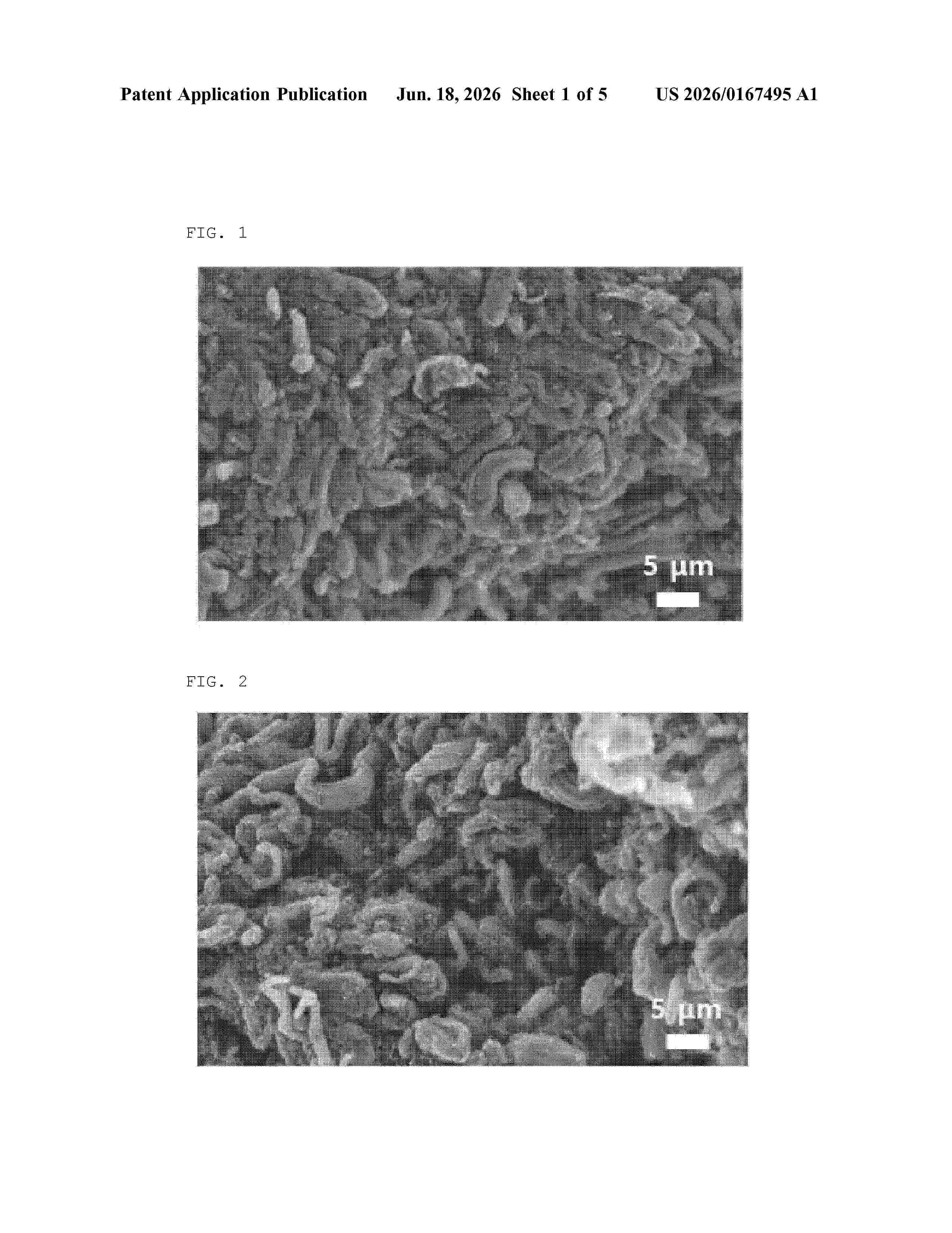
Resumen de: US20260167495A1
A carbon nanotube composition has a volume density of 500/mm3 to 2500/mm3 defined by Equation 1, wherein carbon nanotubes in the carbon nanotube composition have a high bulk density while maintaining a bundled shape, and thus, are excellent in both dispersibility and productivity.
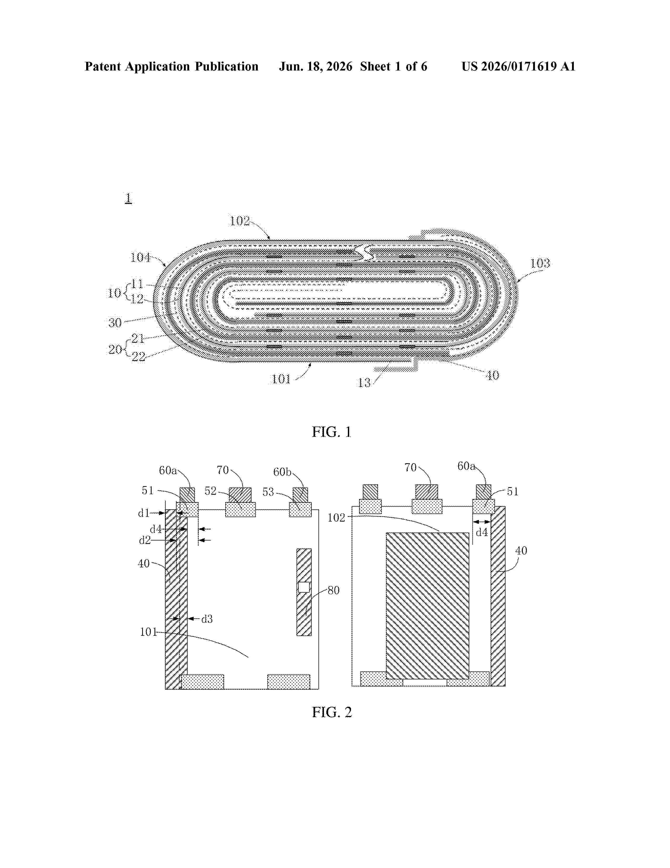
Resumen de: US20260171619A1
0000 A battery cell includes a battery cell body, at least two tabs, a first connector and at least two insulators. The first connector is configured to fasten a tail end of an electrode assembly to an outer surface of the battery cell body; the at least two tabs include a first tab and a second tab, and the at least two insulators include a first insulator and a second insulator, where first ends of the first insulator and the second insulator are all provided on the battery cell body, a second end of the first insulator covers part of the first tab, and a second end of the second insulator covers part of the second tab; and in a width direction of the battery cell body, the first insulator is provided close to the first connector, where at least part of the first insulator is located outside the first connector.
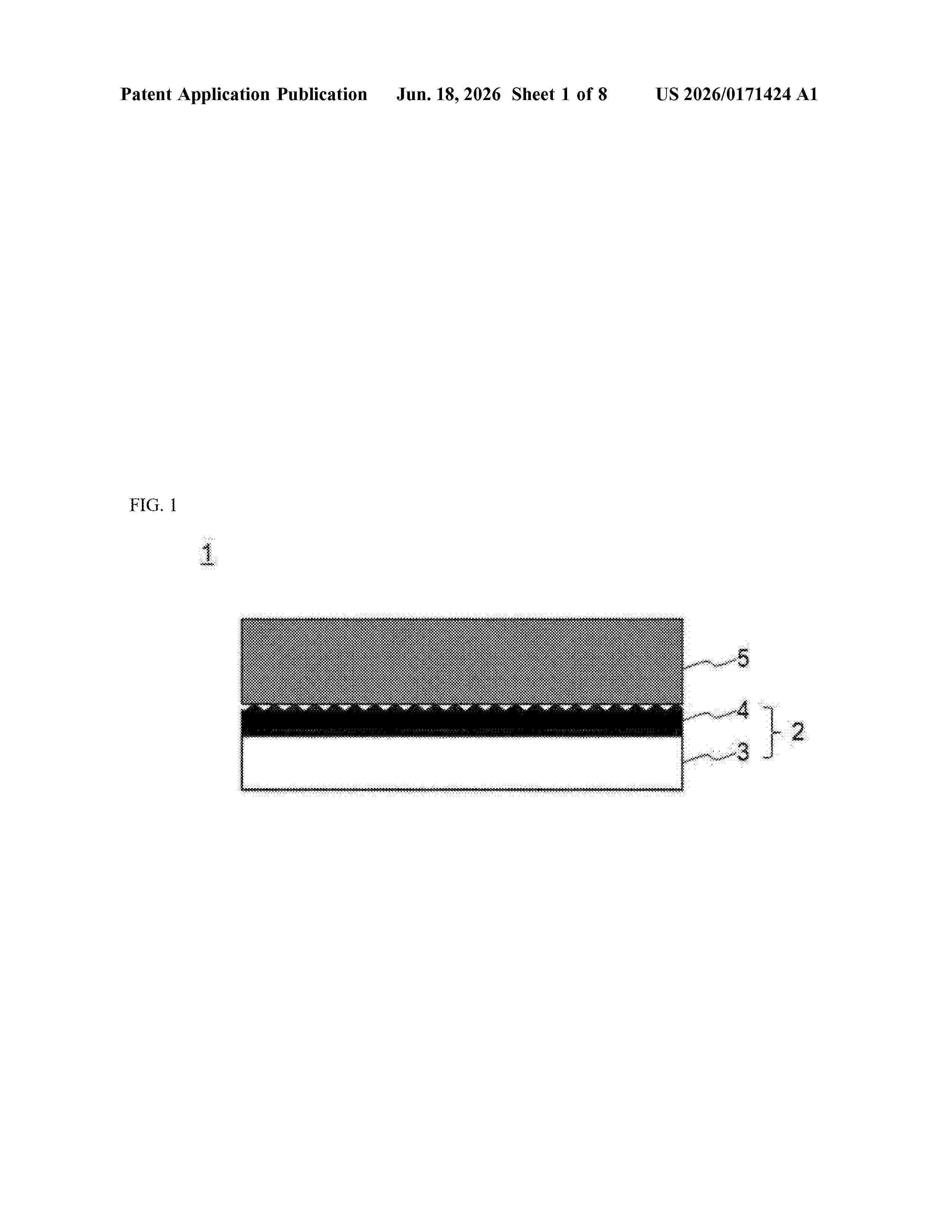
Resumen de: US20260171424A1
0000 A current collector including a metal foil, and a primer coating layer formed on at least one surface of the metal foil. A surface roughness (Ra) of the primer coating layer is 0.01 to 1 μm. The primer coating layer may include a carbon-based material and a binder. A surface of the metal foil may have irregularities formed by a rolling of the primer coating layer.
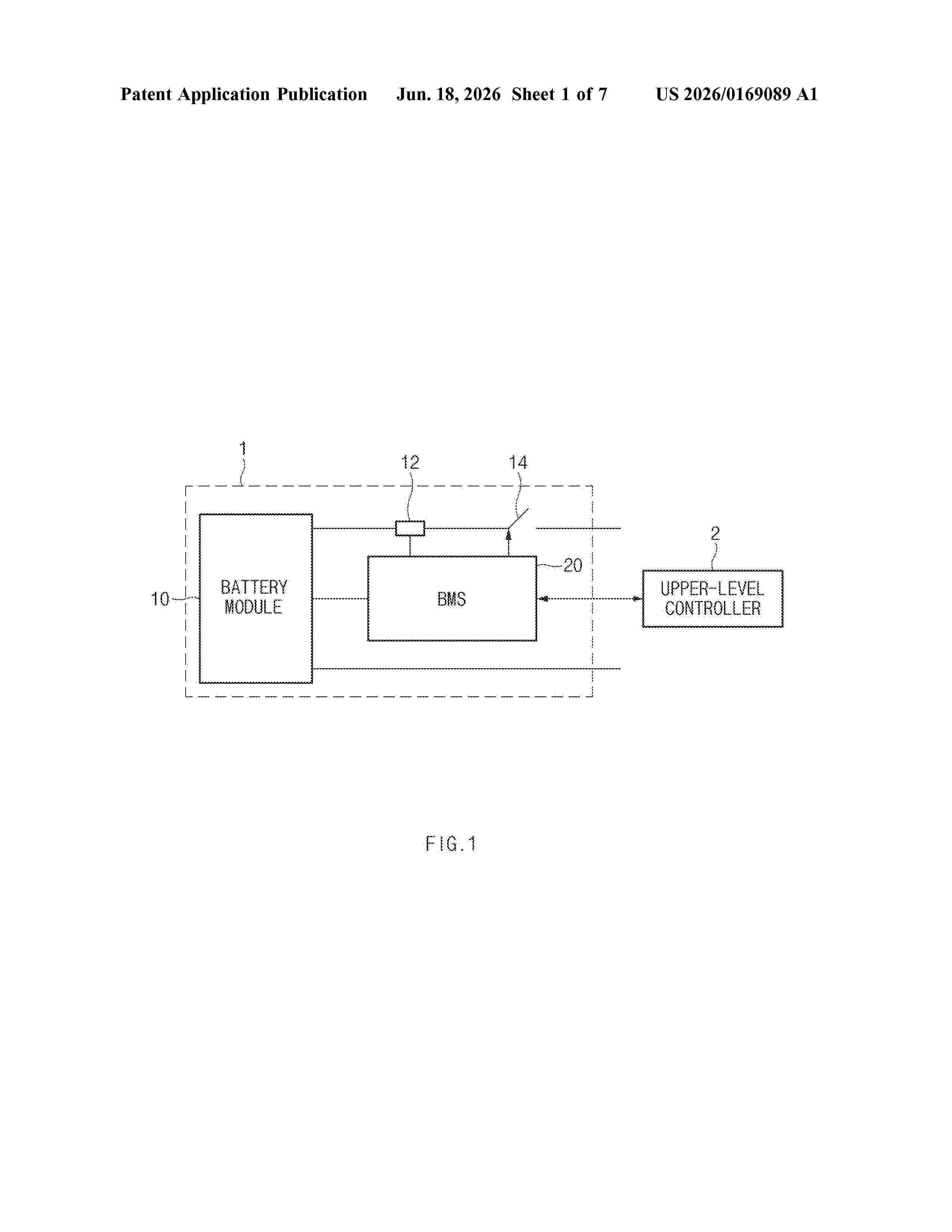
Resumen de: US20260169089A1
0000 A battery life prediction apparatus may include a storing unit configured to store a plurality of pieces of power pattern data used at an actual site, a pattern generating unit configured to generate a test pattern for predicting a life of a battery based on the power pattern data, and a life predicting unit configured to predict a residual life of the battery based on the test pattern. Additionally, the pattern generating unit may generate the test pattern by changing a scale of the power pattern data, and the life predicting unit may communicate the predicted residual life of the battery to a battery management system, and based on the predicted residual life of the battery, the battery management system controls an on or off of a switch connected to the battery.
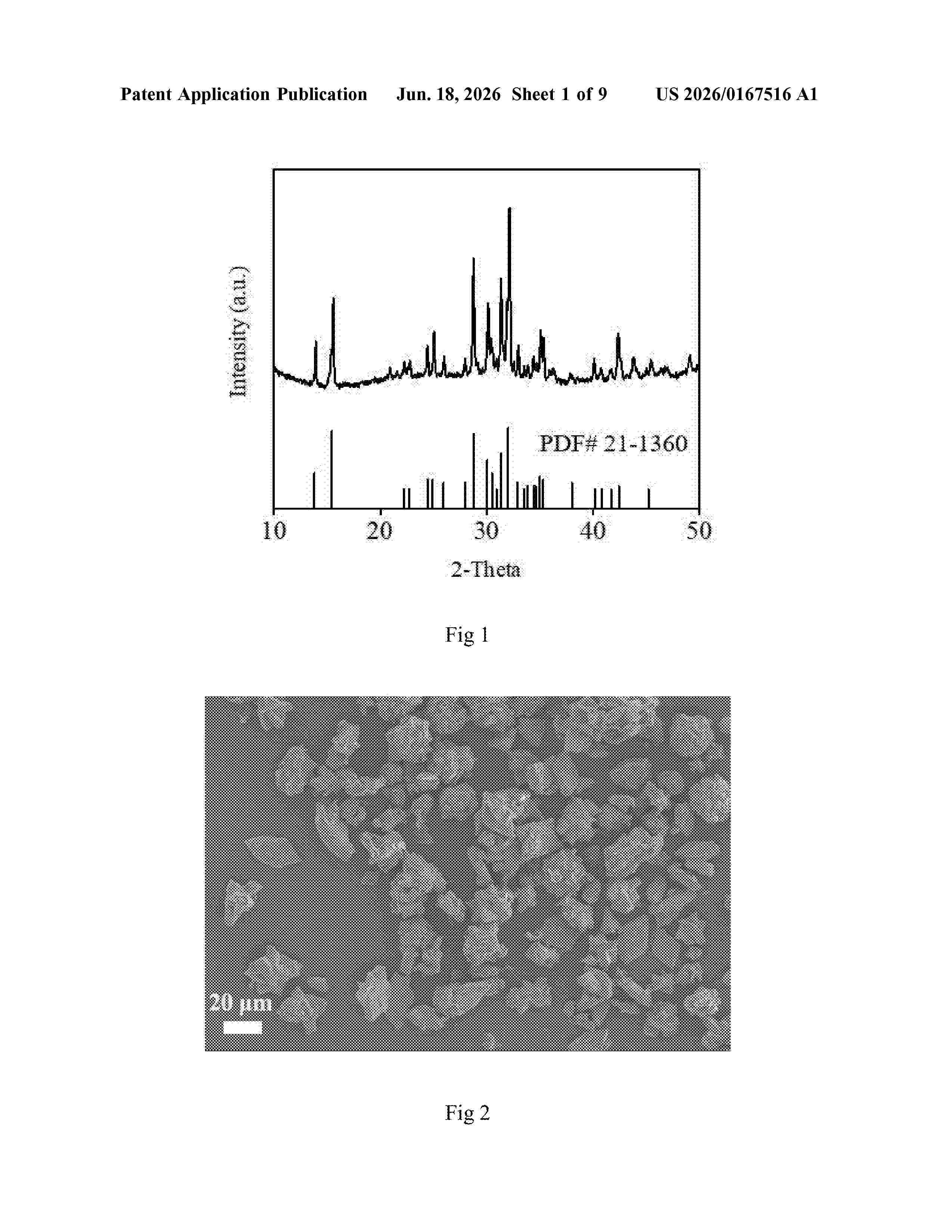
Resumen de: US20260167516A1
The invention discloses a kind of micrometer-scale porous sodium ferrous sulfate/carbon composite cathode materials and sodium-ion or sodium batteries with it. The materials are prepared by a co-precipitation and solid-phase calcination method, and/or involve the metal-doped elements. The materials feature a porous structure with a three-dimensional conductive network, and have a size distribution (2-30 μm) of particles, consisting of a close stack of primary particles of 80-200 nm tightly covered by an amorphous carbon. Micrometer-scale cathode materials deliver a high vibration density, which helps to improve the volumetric energy density of batteries. As a cathode for sodium-ion or sodium batteries, the materials have the advantages of abundant raw materials, low cost, high operating voltage, good rate performance and cycling stability, and simple preparation process. The assembled sodium-ion or sodium batteries show a broad market application prospect with the advantage of high energy density.
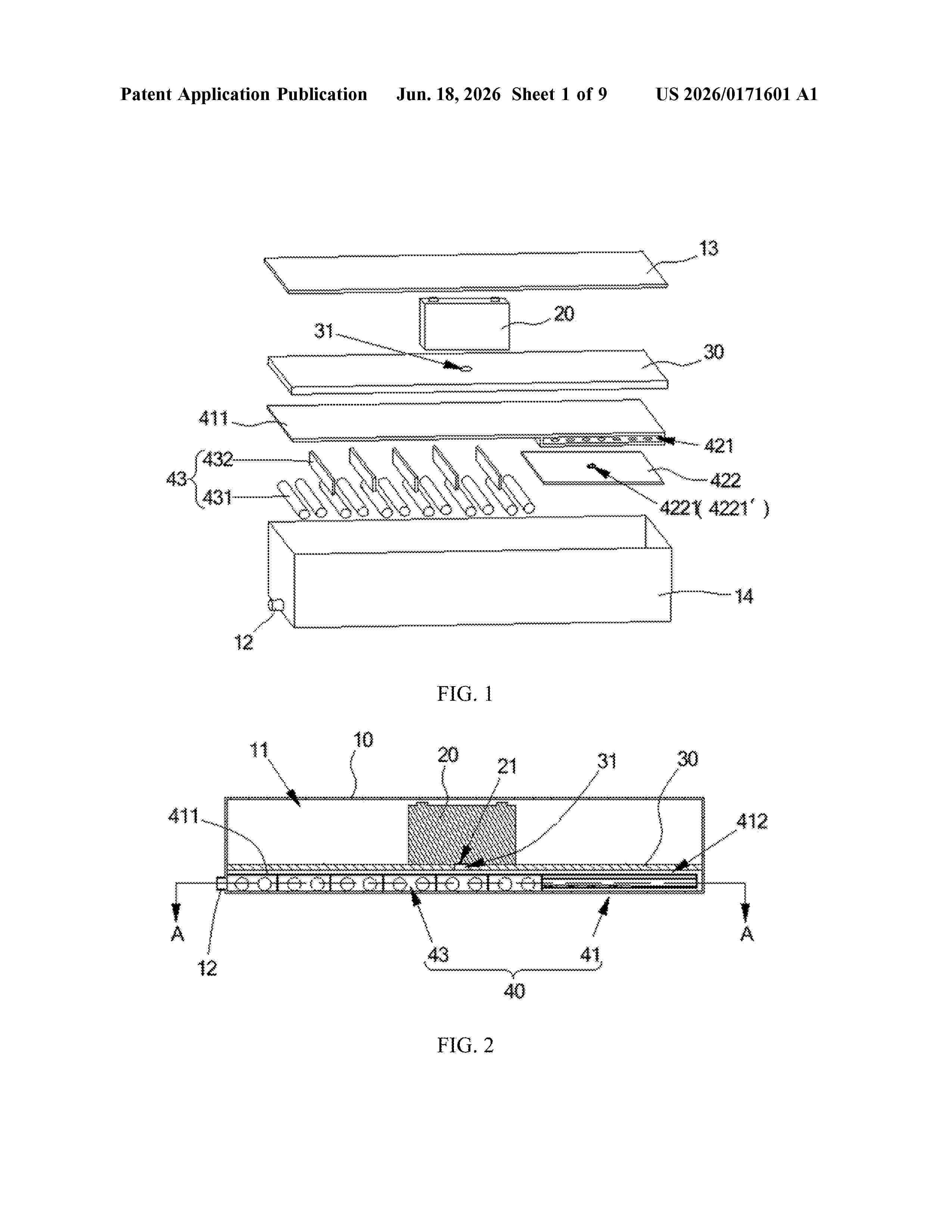
Resumen de: US20260171601A1
A battery and an electric device are disclosed. The battery includes a housing with an inner cavity and a battery cell positioned inside the cavity. The battery cell includes a pressure relief mechanism. A first partition divides the cavity into a first chamber and a second chamber. The battery cell is located in the first chamber. The partition includes a through hole that allows communication between the two chambers. The pressure relief mechanism is aligned with the through hole to direct fumes from the battery cell into the second chamber. A fume processing apparatus is positioned in the second chamber to treat the fumes and discharge the processed fumes outside the battery. This configuration reduces environmental pollution and health hazards caused by fumes generated during thermal runaway of the battery.
Nº publicación: US20260171486A1 18/06/2026
Solicitante:
KIA CORP [KR]
HYUNDAI MOTOR CO [KR]
TOKYO INST OF TECHNOLOGY A JAPANESE NATIONAL UNIVERSITY CORP [JP]
Hyundai Motor Company
Kia Corporation
Tokyo Institute of Technology, a Japanese National University Corp
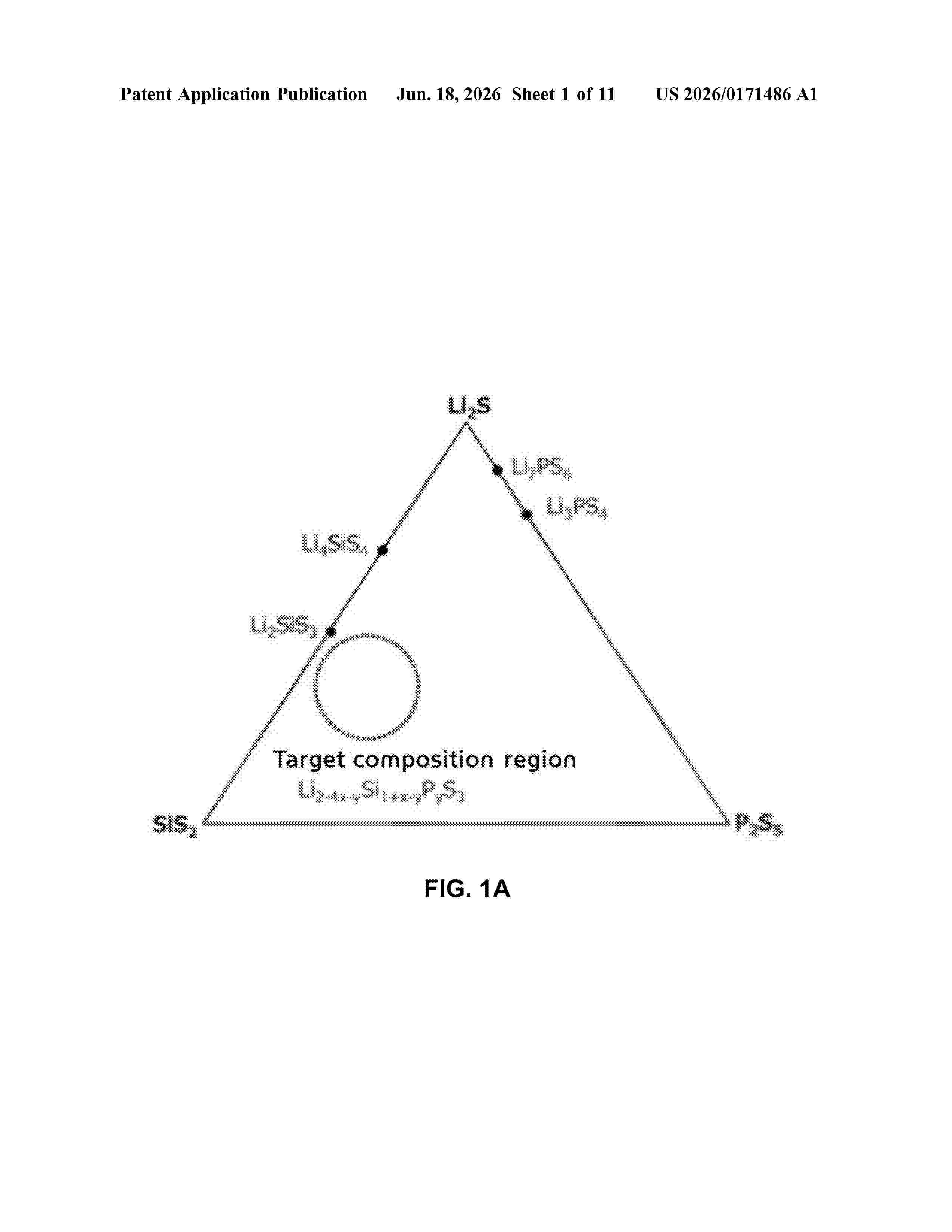
Resumen de: US20260171486A1
Disclosed are a solid electrolyte material including a naturally abundant element as a base, having lithium ion conductivity equal or superior to those of conventional sulfide solid electrolyte materials, being relatively inexpensive, and having a crystal structure, a manufacturing method thereof, and a battery using the same. The solid electrolyte material may include a naturally abundant element as a base, have lithium ion conductivity equal or superior to those of conventional sulfide solid electrolyte materials, be relatively inexpensive, and have a crystal structure. The sulfide solid electrolyte material includes a sulfide compound represented by a formula of Li2-4x-ySi1+x-yPyS3, and x and y satisfy conditions −0.040≤x≤0.095 and 0.036≤y≤0.192.
 BOPI
BOPI
 Sede Electrónica