Si deseas distinguir tus productos, servicios o ambos de los de otra empresa, es posible que necesites una marca o nombre comercial. Descubre qué son, en qué consiste su procedimiento de registro y qué implica.

Información sobre los plazos de presentación de solicitudes de transformación de marcas de la Unión Europea en marca nacional española. Más información


Si tienes un nuevo dispositivo, producto o procedimiento que resuelva un problema técnico o tenga una ventaja práctica, existen distintas formas de protegerlo en España y en otros países. Descubre cómo hacerlo.

¿Tu innovación reside en la estética, la ornamentación o la apariencia de tu producto? Protégela mediante un diseño industrial. Descubre qué derechos confiere el registro y cómo realizar la tramitación.

Las indicaciones geográficas protegen el nombre de un producto originario de una zona geográfica, a la cual le debe una determinada calidad, reputación u otra característica. Descubre qué son, en qué consiste su procedimiento de registro y qué beneficios conceden.

Las patentes publicadas en todo el mundo son una valiosa fuente de información científica, técnica y comercial.

Si eres emprendedor/a o una empresa y quieres potenciar y mejorar la rentabilidad de tu negocio protegiendo de forma adecuada los activos intangibles de tu organización, en este espacio encontrarás lo necesario.


 1422
resultados
1422
resultados
 Última actualización
28/06/2026 [07:11:00]
Última actualización
28/06/2026 [07:11:00]


 Resultados 850 a 875 de 1422

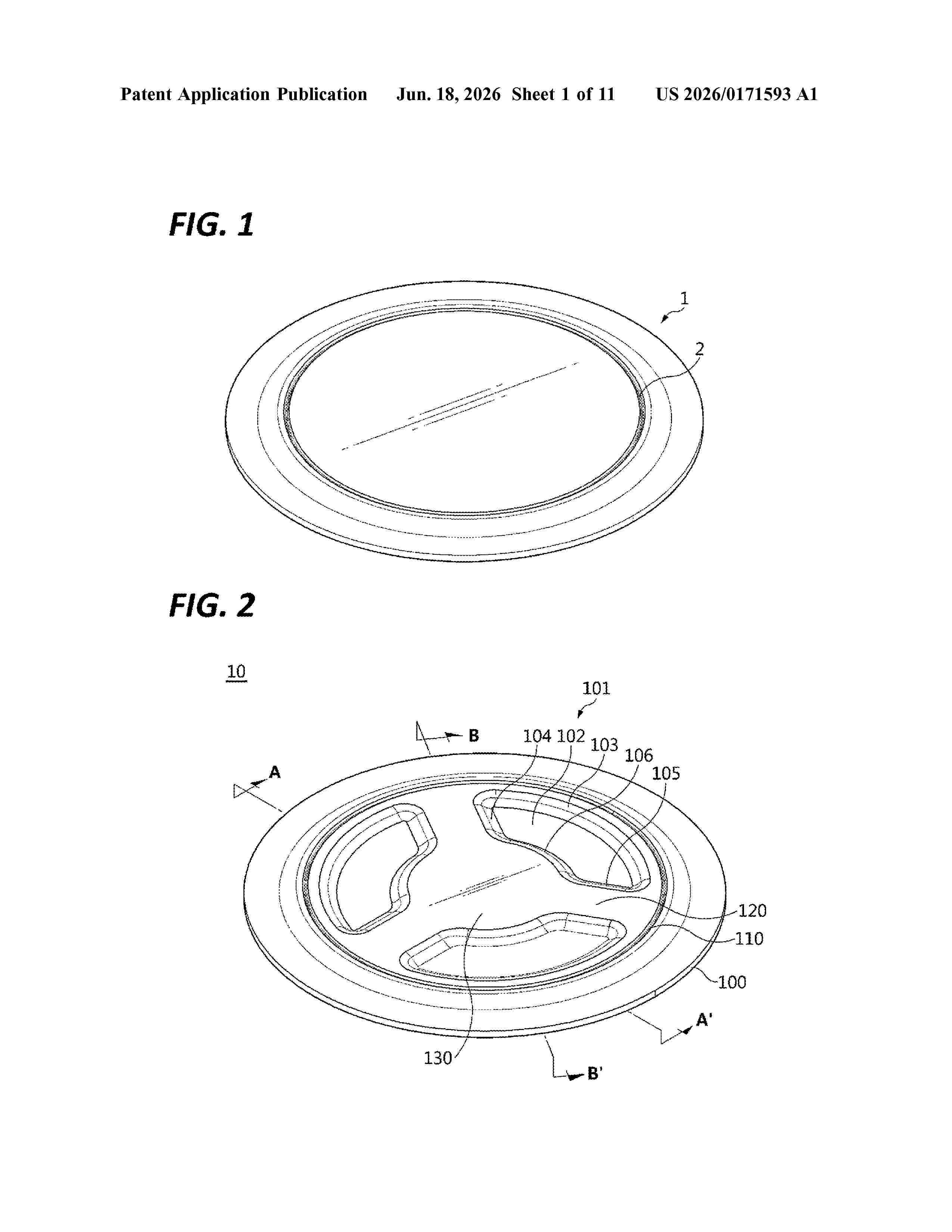
Resumen de: US20260171593A1
A cap plate coupled to a battery can include: a main body that seals the battery can; a vent notch that is formed in the main body, and ruptures when a pressure inside the battery can exceeds a threshold value; and a rupture inducing portion that is formed in the main body while being spaced apart from the vent notch, and induces an occurrence of rupture of the vent notch at a predetermined location.

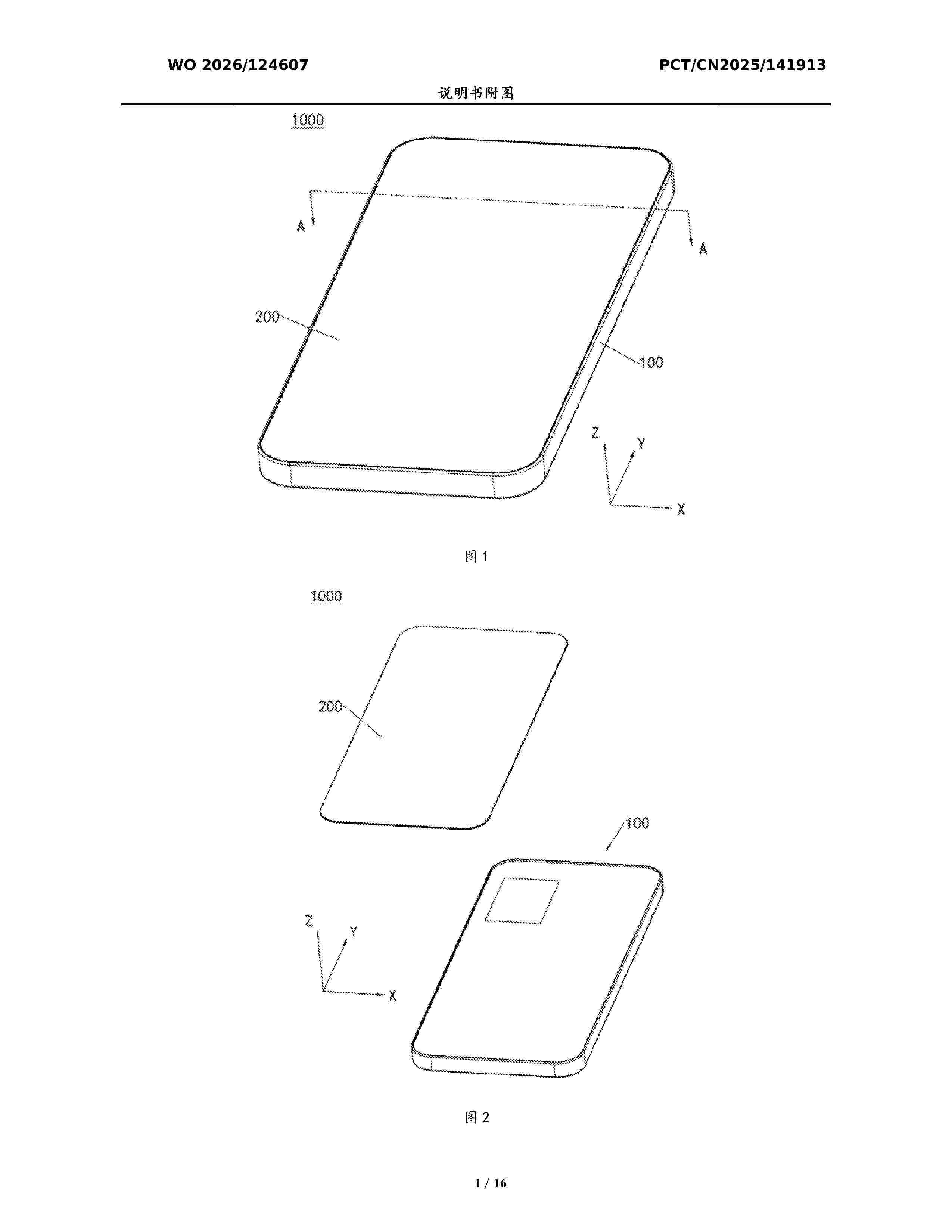
Resumen de: WO2026124607A1
The present application relates to the field of terminal devices, and provides a middle frame and an electronic device. The middle frame comprises a frame, a middle plate, and a first vapor chamber. At least a part of the first vapor chamber is embedded in the middle plate. The frame is fixedly connected to the periphery of the middle plate, and, together with the middle plate and the first vapor chamber, encloses a mounting space of the middle frame. The mounting space is used for accommodating a battery and a circuit board. The middle plate has a first region and a second region that are disposed at an interval. At least a part of the vapor chamber is located in the first region and is disposed at an interval from the second region. The first region is used for carrying the circuit board, and the second region is used for carrying the battery. The middle frame of the present application can achieve both heat dissipation performance and a slim form factor while preventing the formation of local high-temperature hotspots on a screen and ensuring the operating efficiency of the battery.
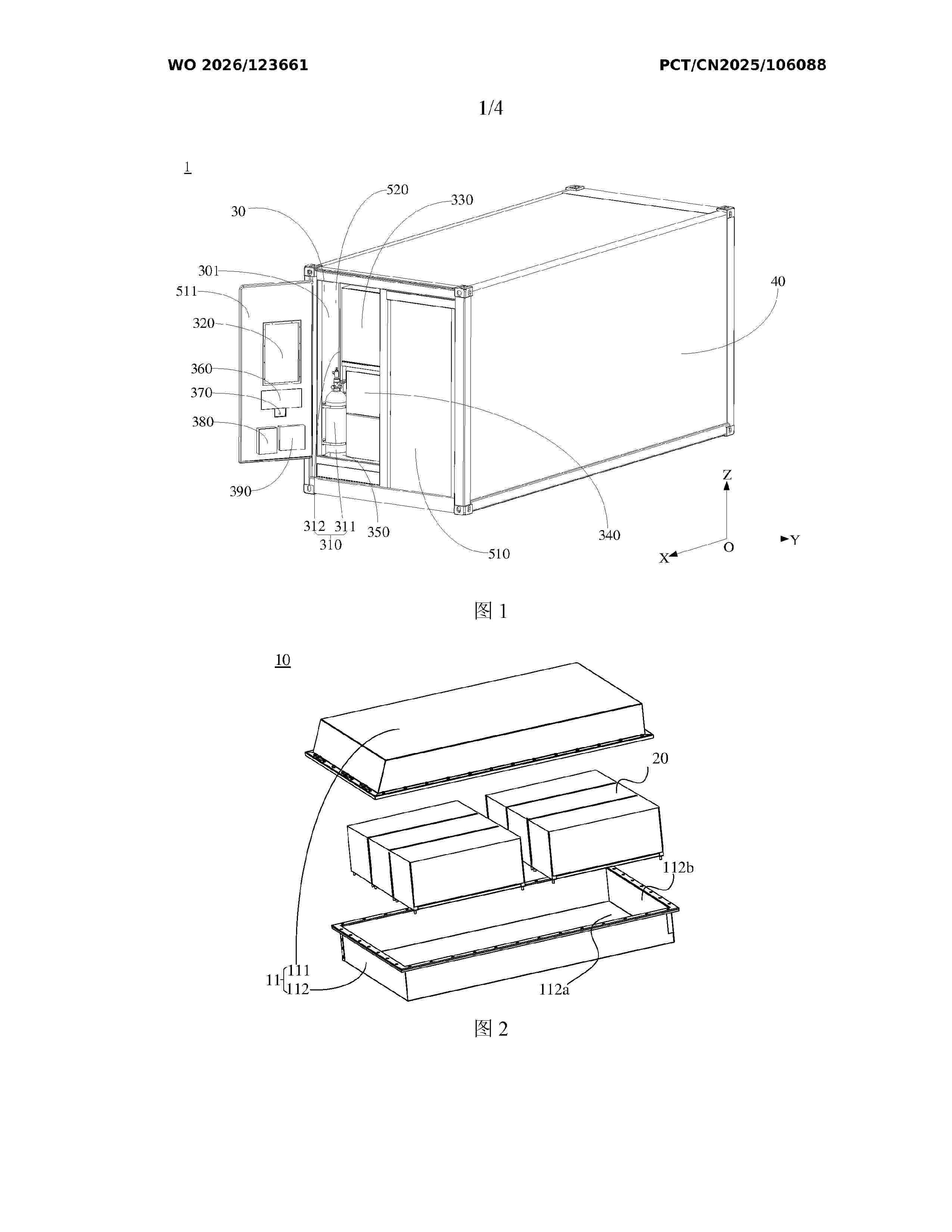
Resumen de: WO2026123661A1
Provided in the embodiments of the present application are an energy storage device and an energy storage system, which can improve the usage performance of the energy storage device. The energy storage device comprises an electrical compartment and a battery compartment, which are arranged in a first direction. The battery compartment is configured to accommodate a battery device, and the electrical compartment is configured to accommodate a firefighting device, a dehumidification device, and a power distribution and main control cabinet. The power distribution and main control cabinet is configured to internally accommodate a power distribution box and a main control box. The energy storage device comprises a first wall and a second wall adjacent to each other. A first opening of the electrical compartment faces the first wall, and a compartment door for covering the first opening is provided on the first wall. The dehumidification device is disposed on the side of the compartment door facing the electrical compartment, and the firefighting device is disposed on the side of the electrical compartment close to the second wall.
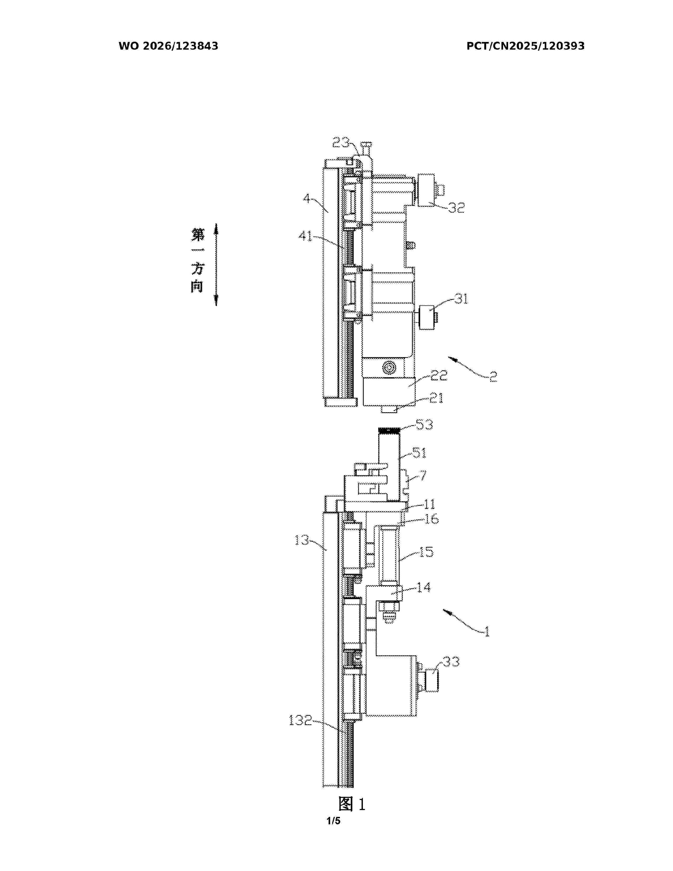
Resumen de: WO2026123843A1
Disclosed in the present invention are a cap press-fitting mechanism and a battery production apparatus. The cap press-fitting mechanism comprises a support assembly and a pressing assembly, wherein the support assembly comprises a first support member and a second support member, the first support member being suitable for supporting a holding cup, and the second support member being capable of sliding relative to the first support member to extend into the holding cup to support a battery inside the holding cup, or to separate from the holding cup; and the pressing assembly is located on one side of the support assembly, the pressing assembly being suitable for press-fitting a cap of the battery into a battery casing. The first support member can support a holding cup containing a battery, and the second support member can slide relative to the first support member to extend into the holding cup to support the battery inside the holding cup. Once the press-fitting of the cap is completed, the second support member can also slide out of the holding cup, helping reduce friction against the battery, and thereby preventing scratches on electrodes of the battery.
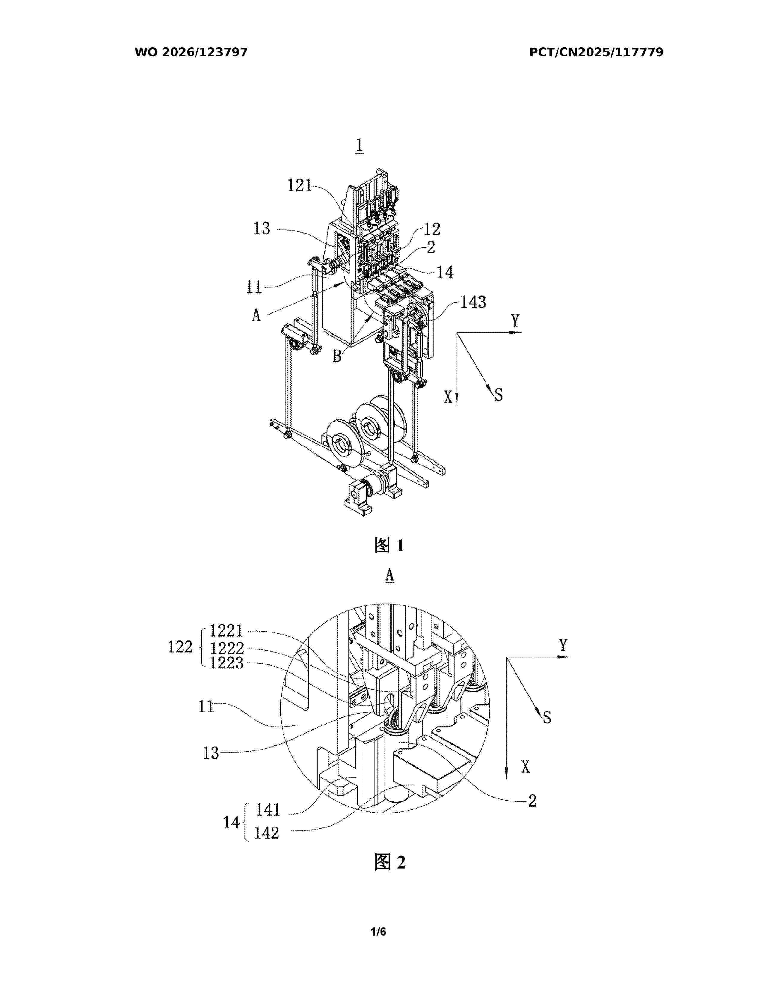
Resumen de: WO2026123797A1
A welding inspection device and a battery production apparatus. The welding inspection device is used for inspecting the welding strength between a bent portion and a cap of a battery, and comprises a frame, a clamping assembly and a limiting assembly. The clamping assembly is movably arranged on the frame in a first direction and is configured to grip the cap; and the limiting assembly is configured to limit the relative movement of a body portion and a battery cell.
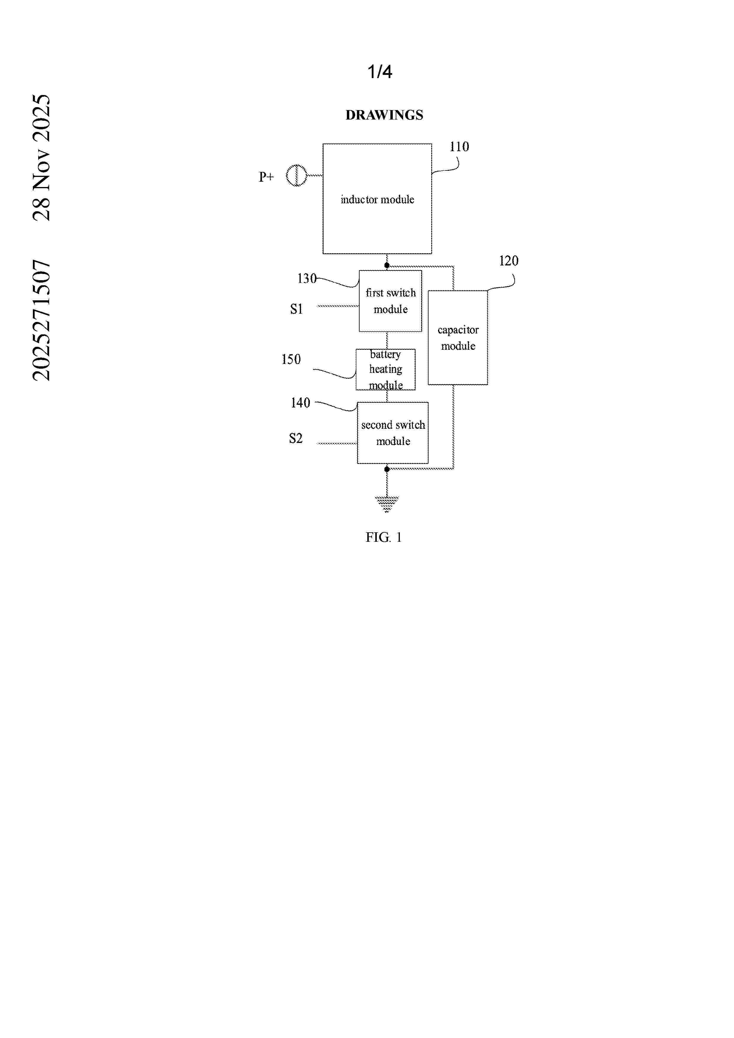
Resumen de: AU2025271507A1
A battery heating circuit, a battery heating system, and a battery assembly are provided. The battery heating circuit included an inductor module, a capacitor module, a first switch module, a second switch module, and a battery heating module. A control terminal of the first switch module is configured to receive a first switch control signal. A control terminal of the second switch 5 module is configured to receive a second switch control signal. The first switch control signal or the second switch control signal is a pulse signal. Heating input power of the battery heating module is controlled through the pulse signal and energy storage in the inductor module and the capacitor module, such that a power-controllable battery heating method may be implemented. ov o v P+ inductor module first switch S1 module capacitor module battery heating module second switch S2 module ov o v m o d u l e m o d u l e s e c o n d s w i t c h m o d u l e
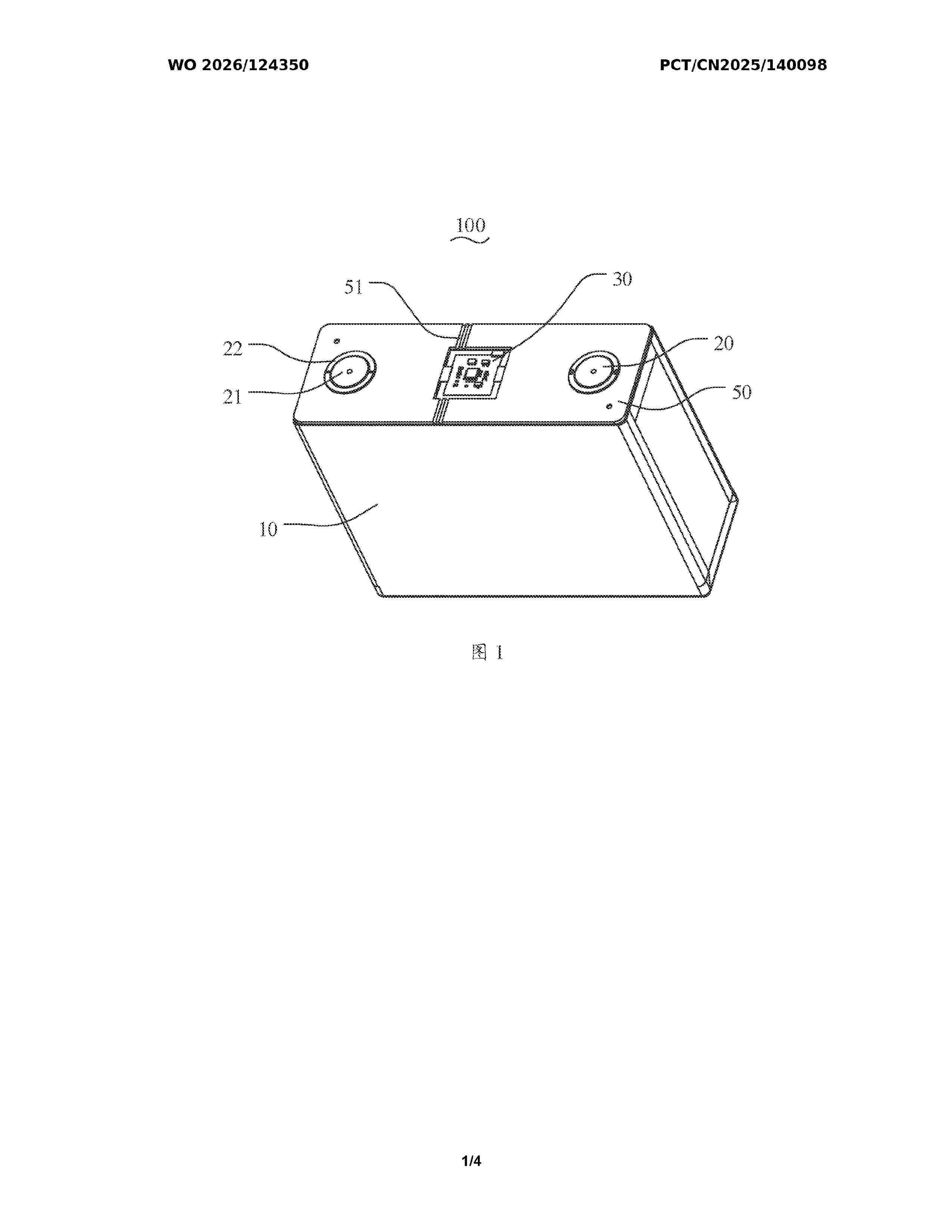
Resumen de: WO2026124350A1
Disclosed in the present application are a battery cell and a battery pack. The battery cell comprises a battery cell main body, at least one post and a battery cell information acquisition module, the at least one post being connected to the battery cell main body, and the battery cell information acquisition module being connected to the at least one post. The post comprises a first connection portion connected to the battery cell main body and a second connection portion located on a side surface of the first connection portion and connected to the first connection portion, the first connection portion being used to be connected to an external component, and the second connection portion being used to be connected to the battery cell information acquisition module. Signal acquisition of the battery cell information acquisition module is separated from a high-current connection between the battery cell main body and the external component, which ensures power supply and information acquisition of the battery cell information acquisition module while ensuring connection of the external component during system integration, and prevents welding of the battery cell information acquisition module and the post from affecting the welding flatness between the external component and the post, thereby avoiding welding splashing, and improving product stability and welding process quality.
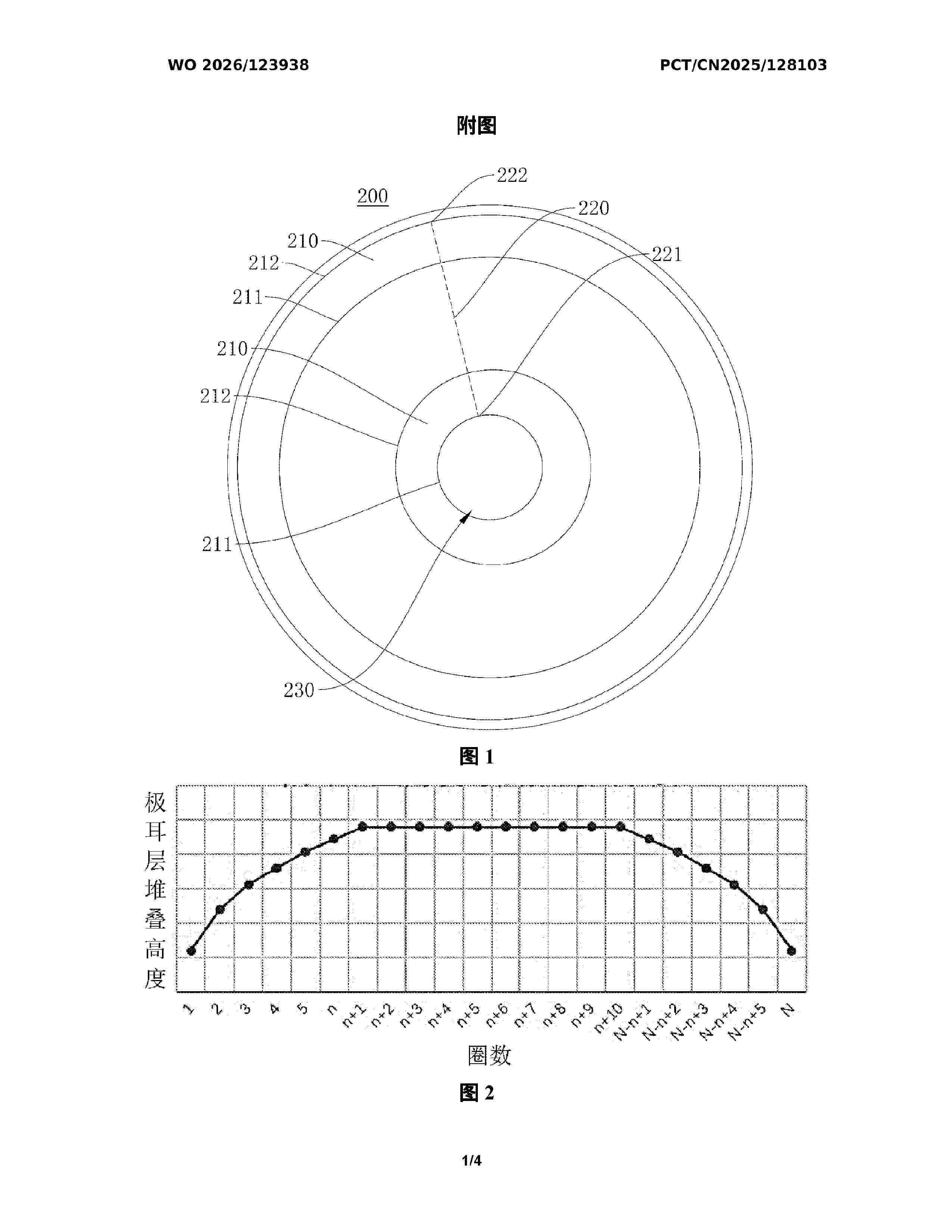
Resumen de: WO2026123938A1
Provided in the present application are a battery cell and a battery pack, relating to the technical field of batteries. The battery cell comprises a wound core and a current collector plate. The current collector plate is welded to a tab layer of the wound core along a preset welding trajectory, wherein a first end of the preset welding trajectory is located between a root portion and an end portion of a first-turn tab, and a second end of the preset welding trajectory is located between a root portion and an end portion of an Nth-turn tab; one of the first end and the second end serves as a welding start point and the other serves as a welding end point; and the following conditions are satisfied: 0.95D1≤s≤0.99D1, and 1.01dN≤f≤1.05dN. In this way, the impact on the welding quality from the condition where inner and outer turns of a tab layer are low while a middle plane is high is reduced, thereby prolonging the cycle life of the battery cell and also reducing the risk of a short circuit in the battery cell.
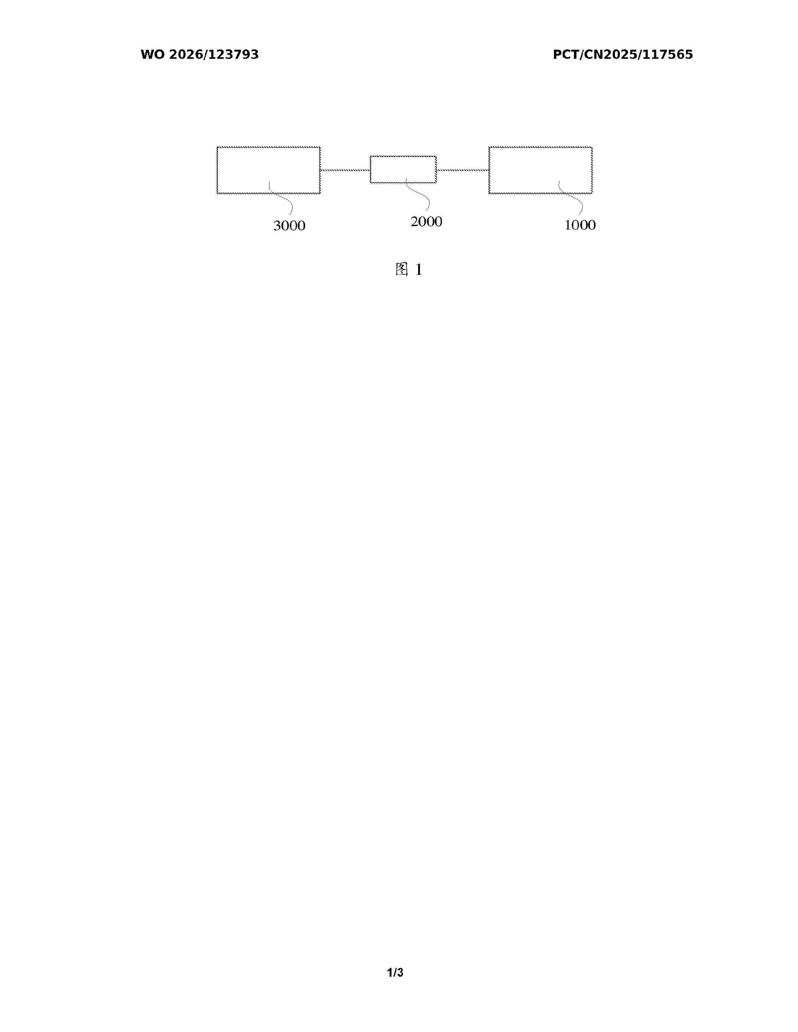
Resumen de: WO2026123793A1
The present application relates to a battery device, an electric device, an energy storage device, an energy storage system, and a charging network. The battery device comprises: a housing provided with an accommodating cavity; a battery cell provided in the accommodating cavity, wherein an explosion-proof valve is provided on a first wall of the battery cell; a heat exchange plate provided in the accommodating cavity and located between the first wall and a cavity wall of the accommodating cavity, the heat exchange plate being provided with a first pressure relief port corresponding to the explosion-proof valve; and an isolation plate provided between the first wall and the heat exchange plate, at least part of the isolation plate being located in the first pressure relief port, and the part located in the first pressure relief port being provided with a second pressure relief port corresponding to the explosion-proof valve. In the present application, the first pressure relief port is mated with the second pressure relief port to implement smooth spraying of the explosion-proof valve, and the part of the isolation plate located in the first pressure relief port can also block a sprayed high-temperature medium, so that the probability that the high-temperature medium is sprayed onto the heat exchange plate or other structures in the battery device is reduced, thereby protecting the overall structure of the battery device.
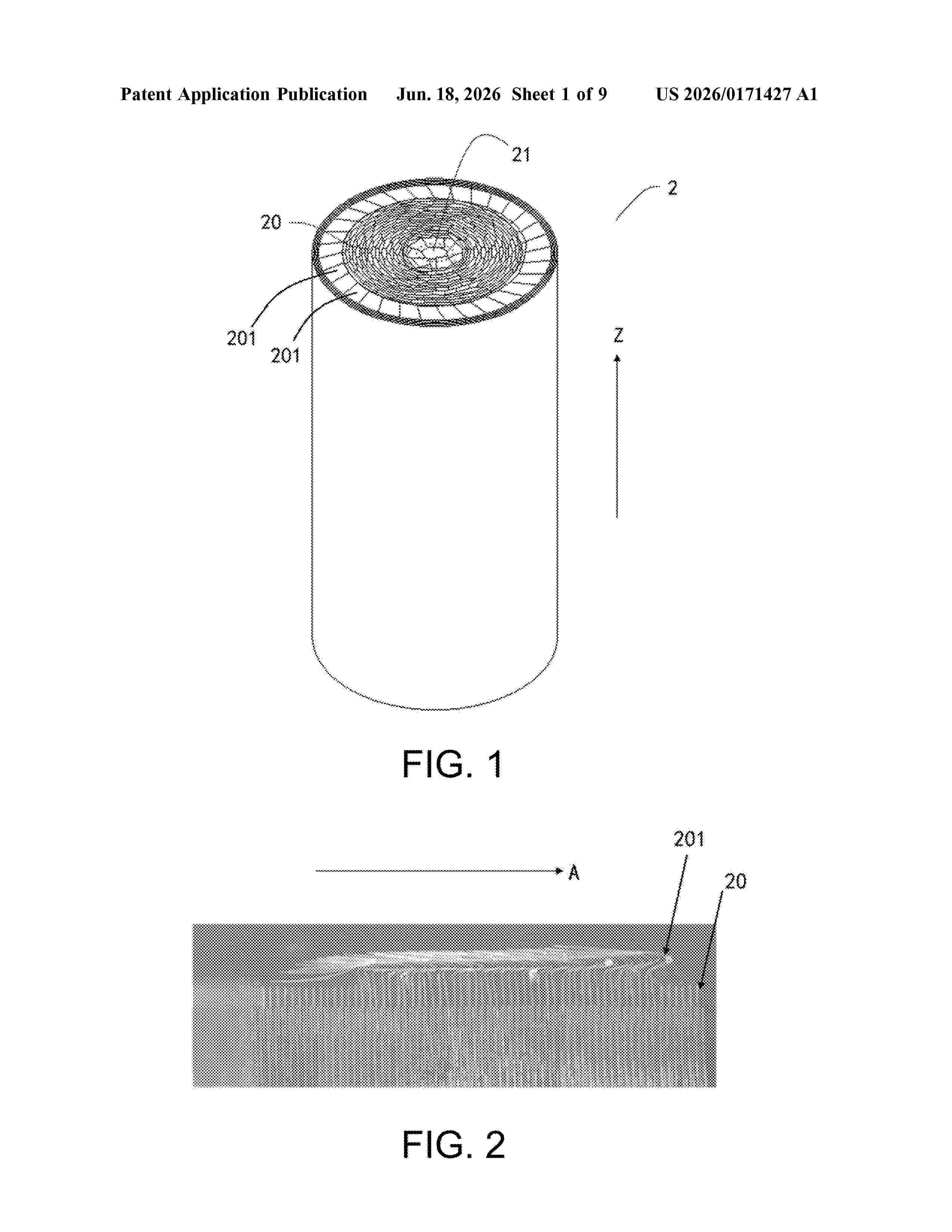
Resumen de: US20260171427A1
A battery cell, a battery pack, and an electronic device are provided. The battery cell includes a housing, an electrode assembly, and a current collecting plate. A first extension portion of the current collecting plate extends from an outer edge of a main body portion along a radial direction of the main body portion to be in contact with an outer tab. One end of a second extension portion is connected to the main body portion between the two adjacent first extension portions. An outer edge of the second extension portion is formed with an outer edge surface along a circumferential direction. The outer edge surface is projected orthographically along a height direction onto a plane where the outer tab is located that is perpendicular to the height direction to form an outer edge surface projection at least partially overlapping each outer tab between the two adjacent first extension portions.
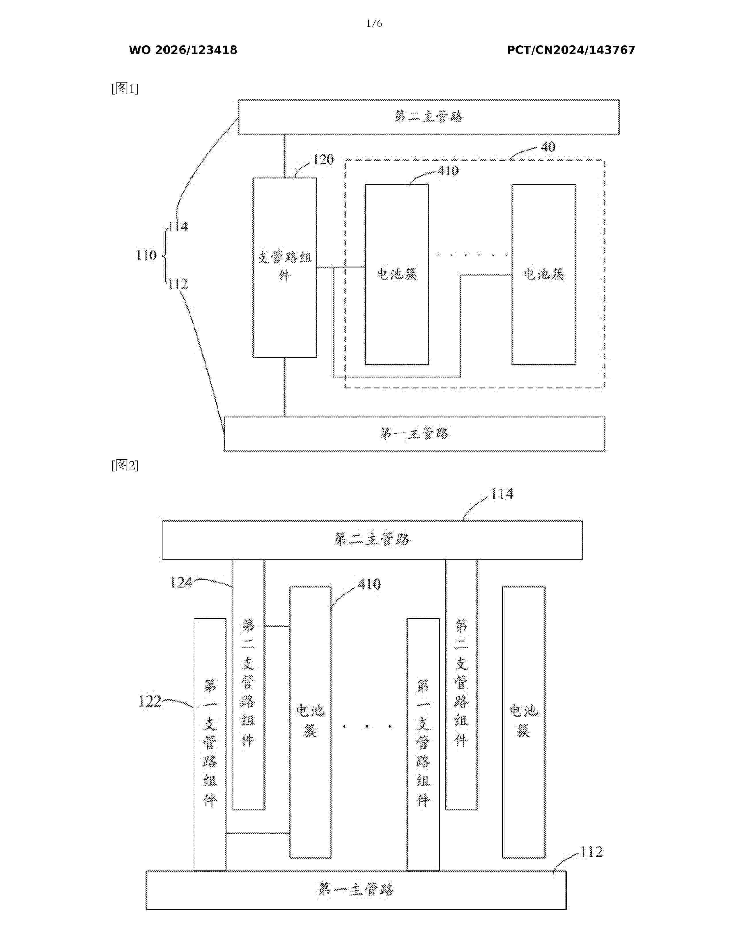
Resumen de: WO2026123418A1
Disclosed in the present application are a liquid-cooling piping structure, a cooling device and an energy storage system. In the structure, a first main pipe is arranged adjacent to the bottom of a battery system, and a second main pipe is arranged adjacent to the top of the battery system; a branch pipe assembly is in communication with the first main pipe, so as to form a first transfer passage; the branch pipe assembly is in communication with the second main pipe, so as to form a second transfer passage; and the branch pipe assembly is configured to bring battery clusters in the battery system into communication with each other, and a coolant is transferred through the first transfer passage, the battery clusters and the second transfer passage, so as to regulate the temperature of the battery clusters. Liquid-cooling temperature regulation of the battery clusters is thus achieved.
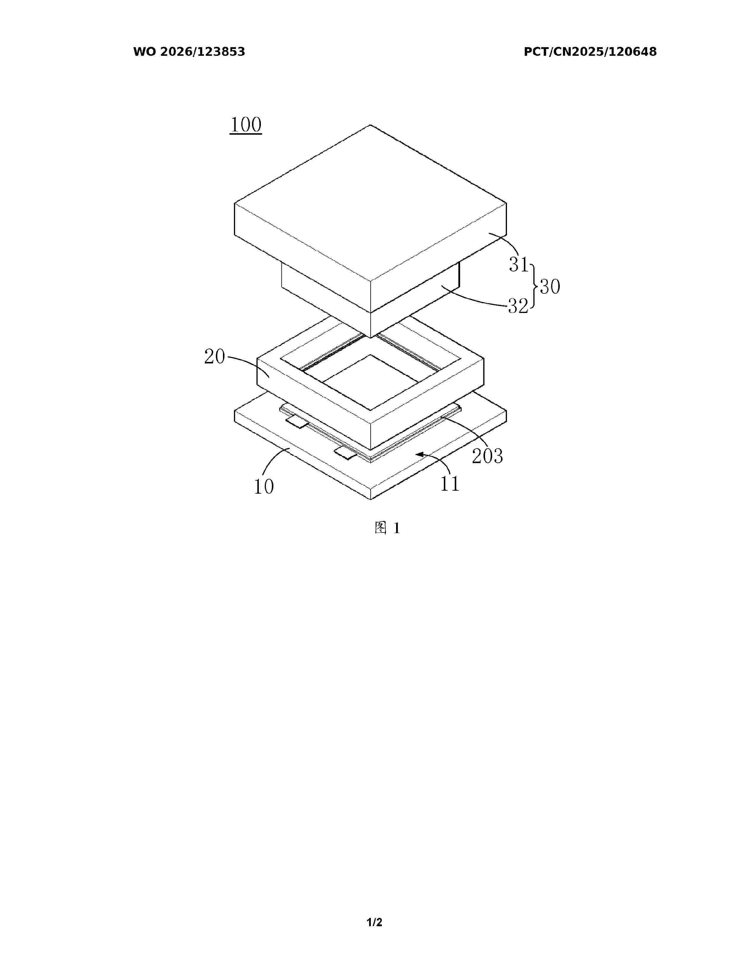
Resumen de: WO2026123853A1
The present application relates to a pressing apparatus and a battery production device. The pressing apparatus comprises: a support member, having a support surface for supporting a first electrode sheet; a positioning assembly, disposed on the support surface and defining a first positioning space and a second positioning space, the first positioning space and the second positioning space being disposed along a stacking direction of the first electrode sheet and a second electrode sheet, and the first positioning space being located between the support surface and the second positioning space; and a first pressure assembly, movably disposed on the side of the positioning assembly away from the support member along the stacking direction, and used for applying pressure to the first electrode sheet and the second electrode sheet in the positioning assembly to form a laminated electrode sheet unit. In the present application, the positioning assembly can protect an overhang region, so that the pressing apparatus can apply high pressure to the first electrode sheet, an electrolyte layer, and the second electrode sheet, thereby protecting the overhang region from being crushed, and enabling the first electrode sheet, the electrolyte layer, and the second electrode sheet to be more closely attached.
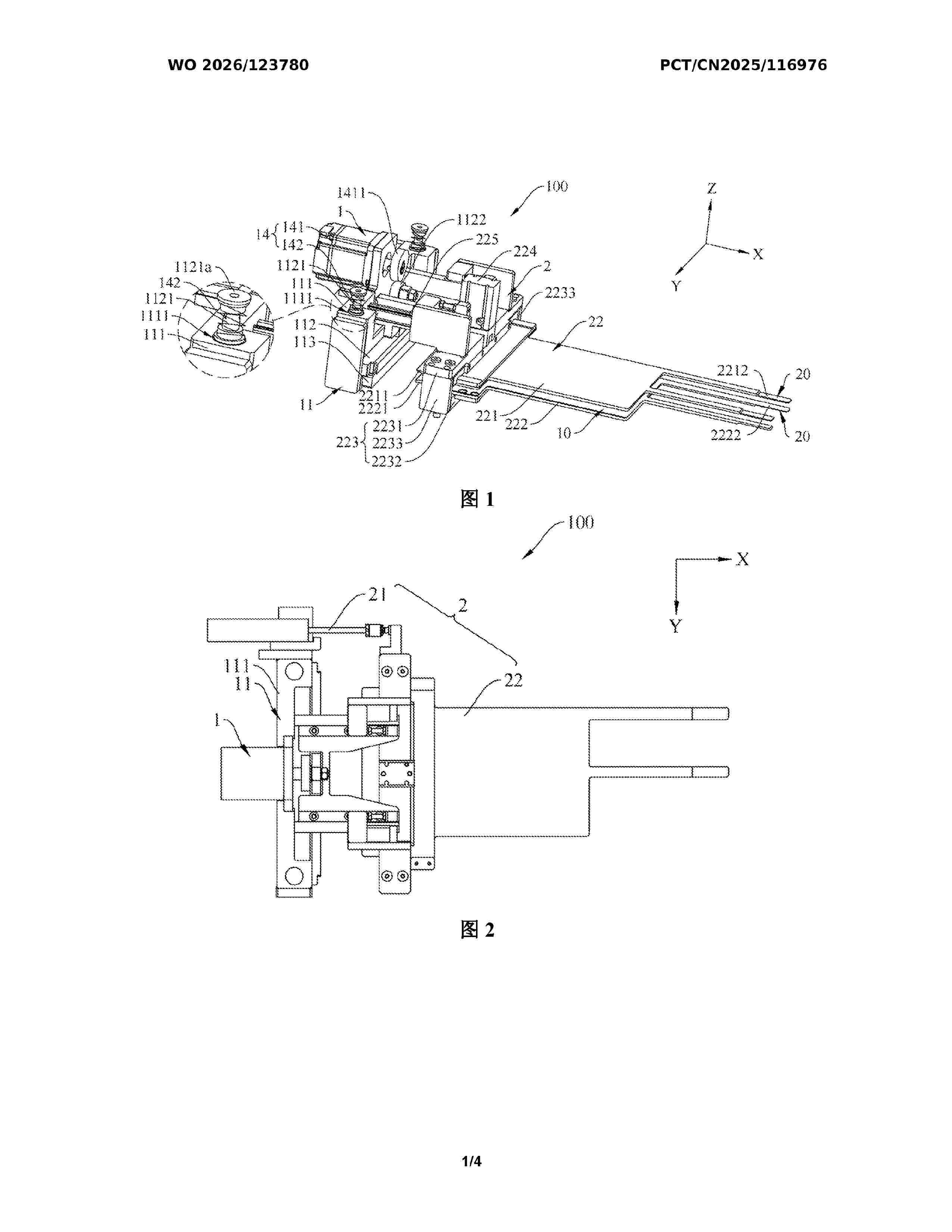
Resumen de: WO2026123780A1
A sheet inserting apparatus (100) and a cell winding device (200). The sheet inserting apparatus (100) comprises: a feeding mechanism (1), wherein the feeding mechanism (1) is configured to convey a material strip (L) along a preset trajectory; and a material supporting mechanism (2), wherein the material supporting mechanism (2) comprises a material supporting driving member (21) and a material supporting assembly (22), the material supporting assembly (22) is located downstream of the feeding mechanism (1), and the material supporting driving member (21) is disposed on the feeding mechanism (1) and is configured to drive the material supporting assembly (22) to move towards or away from the feeding mechanism (1) along the preset trajectory.
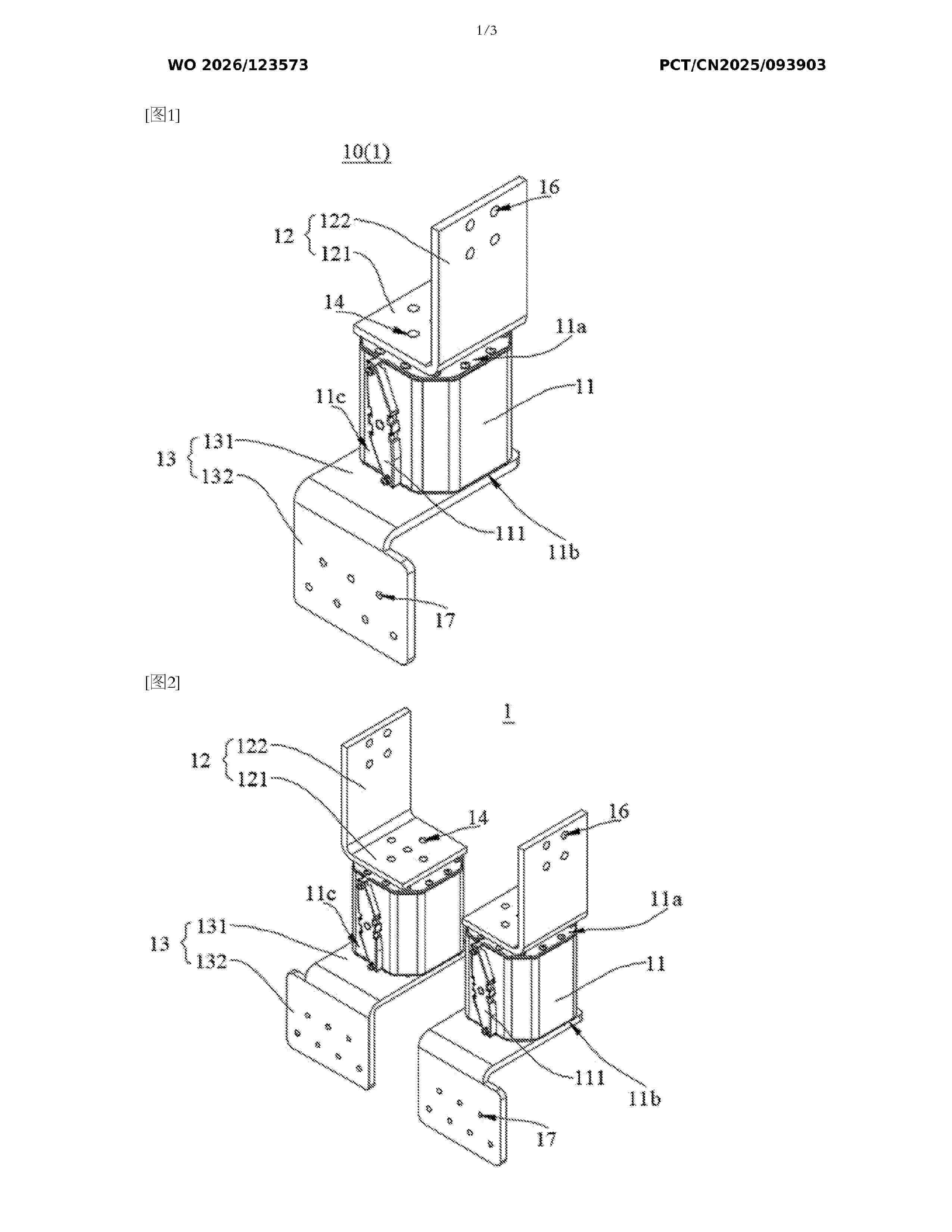
Resumen de: WO2026123573A1
The present application provides a fuse assembly and a combiner cabinet. The fuse assembly comprises a fusing unit; the fusing unit comprises a fuse, a first connecting piece and a second connecting piece; the first connecting piece comprises a first part and a second part, the first part is detachably connected to a first end surface of the fuse, and the second part extends in the direction of the first part away from a first end surface; the second connecting piece comprises a third part and a fourth part, the third part is detachably connected to a second end surface of the fuse, and the fourth part extends in the direction of the third part away from the second end surface; and the second part and the fourth part are arranged on different sides of the fuse.
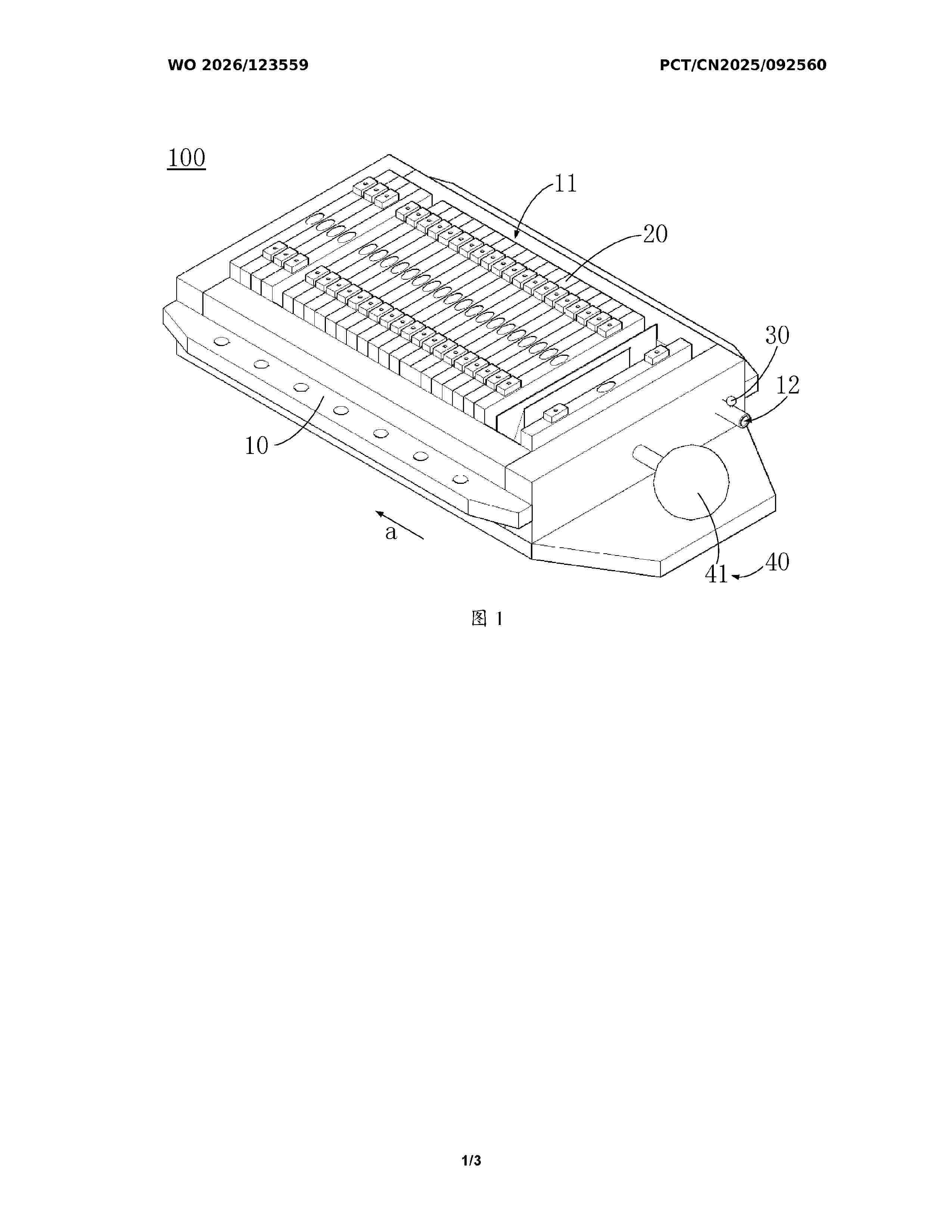
Resumen de: WO2026123559A1
The present application relates to a battery apparatus and an electrical device. The battery apparatus comprises: a box body, having an accommodating cavity; a solid-state battery cell, disposed in the accommodating cavity and filled with a tracer gas; a force applying assembly, movably disposed on the box body and having a first position pressed against the solid-state battery cell and a second position separated from the solid-state battery cell; and a control assembly, disposed on the box body and communicatively connected to the force applying assembly, the control assembly being configured to be able to control the force applying assembly to switch from the first position to the second position when the concentration of tracer gas in the accommodating cavity reaches a preset value, so that the battery apparatus stops charging and discharging. The force applying assembly of the present application can apply a pre-tightening force to the solid-state battery cell at the first position; when the solid-state battery cell experiences a leak, the control assembly controls the force applying assembly to switch from the first position to the second position, such that a solid-solid contact interface between an electrode sheet and an electrolyte layer is separated, and the battery apparatus can promptly stop charging and discharging.
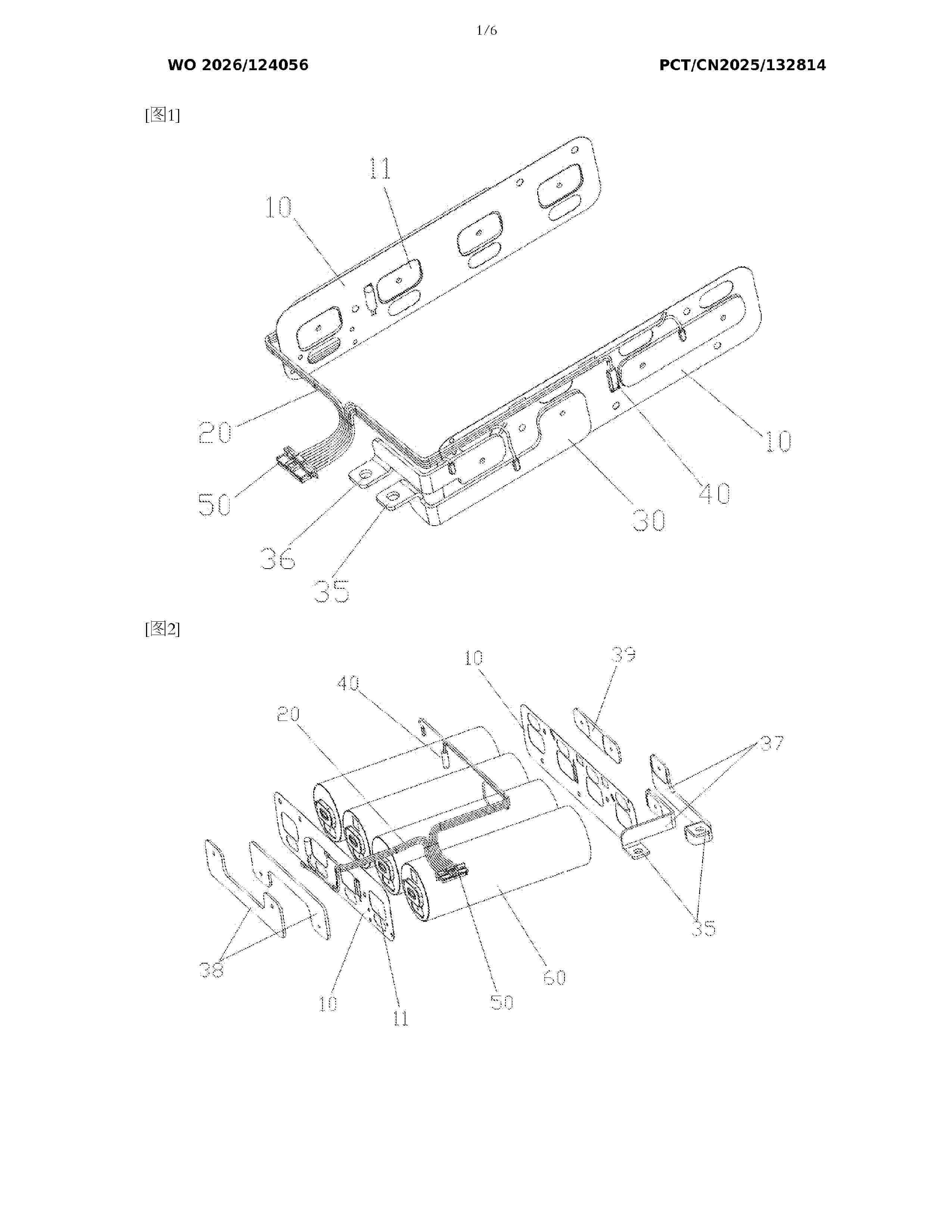
Resumen de: WO2026124056A1
The present application provides a battery module, comprising battery cells; a plurality of mounting films, wherein both ends of the battery cells are provided with mounting films; conductive busbars, wherein the conductive busbars are arranged on the sides of the mounting films facing away from the battery cells, the mounting films are provided with through holes, and terminals of the battery cells pass through the through holes and are electrically connected to the conductive busbars; and a housing, wherein the battery cells, the mounting films and the conductive busbars are all arranged in the housing, and the housing presses the mounting films and the conductive busbars to maintain the mounting films and the conductive busbars in electrical contact with the battery cells.
Resumen de: US20260167059A1
0000 An electric energy managing system applied to an electric vehicle, comprises the following components. A first state-of-health (SOH) calculating circuit, calculates an overall SOH of a fuel cell of the electric vehicle. The overall SOH is associated with an aging condition of the fuel cell. A second SOH calculating circuit, calculates a SOH of a lithium battery of the electric vehicle. The SOH is associated with an aging condition of the lithium battery. An electric energy distribution circuit, calculates a first predefined ratio of an output power of the fuel cell with respect to a total electric energy demand of the electric vehicle according to the overall SOH of the fuel cell and the SOH of the lithium battery, and controls a second predefined ratio of the output power of the fuel cell with respect to an output power of the lithium battery according to the first predefined ratio.
Resumen de: WO2026123771A1
The present application provides a silicon-based negative electrode material having an artificial SEI film, and a preparation method therefor and the use thereof. The silicon-based negative electrode material comprises a silicon-based material, and a carbon layer and a conductive artificial SEI composite layer which are arranged on the silicon-based material, wherein the carbon layer is located between the silicon-based material and the conductive artificial SEI composite layer; and the conductive artificial SEI composite layer is obtained by reacting a reactive precursor with a reactive conductive material. In the present application, by means of the design of a three-layer structure and interaction between the layers, the uniform, tight and stable coating of a nanometer conductive material is achieved, the utilization rate of the conductive material is improved, the silicon-based negative electrode material has low expansion, a high capacity, and a good conductivity and cycling stability, and the cycle performance of a lithium-ion battery comprising same is improved. When the silicon-based negative electrode material is used for manufacturing a negative electrode sheet and a battery, an extra nanometer conductive material does not need to be added, thereby simplifying a manufacturing process for the battery and significantly reducing the use cost of the silicon-based negative electrode material.
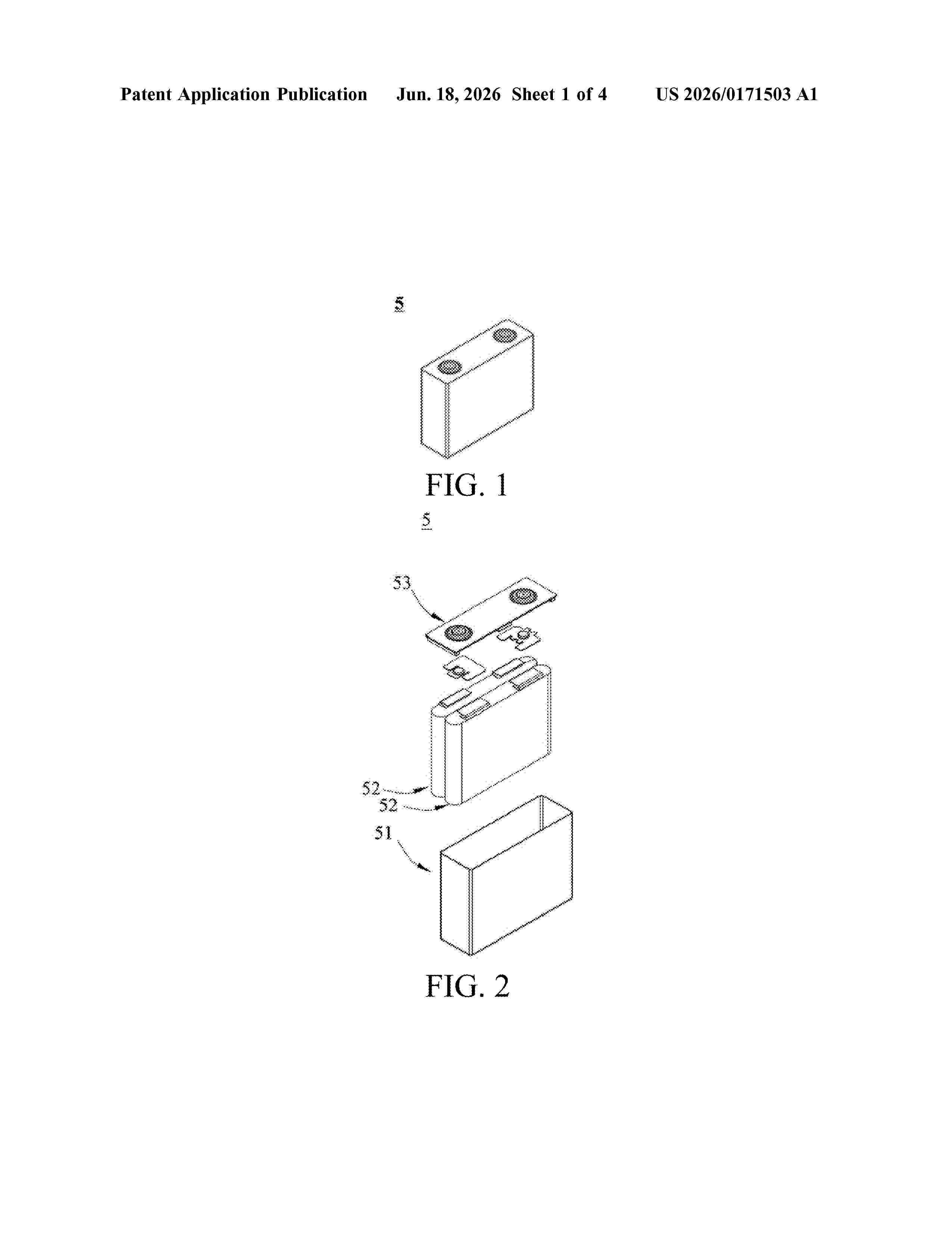
Resumen de: US20260171503A1
0000 An electrolyte solution for a lithium metal battery, a lithium metal battery and an electrical device. The electrolyte solution for a lithium metal battery includes an organic solvent. The organic solvent includes a phosphate compound including a silicon-containing group and at least one phosphate group, where an oxygen atom of at least one phosphorus-oxygen single bond in the phosphate group is connected to a silicon atom of the silicon-containing group by a covalent single bond.
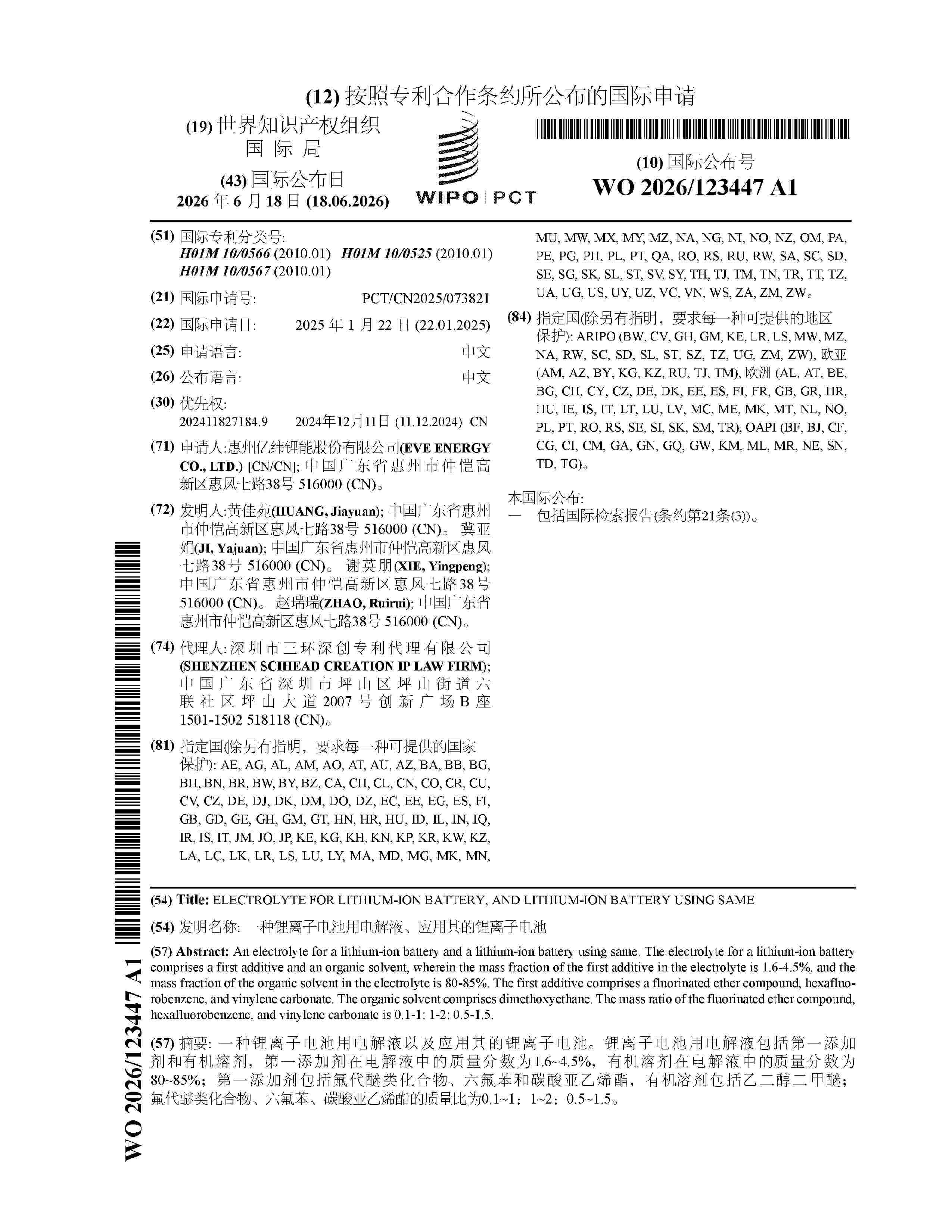
Resumen de: WO2026123447A1
An electrolyte for a lithium-ion battery and a lithium-ion battery using same. The electrolyte for a lithium-ion battery comprises a first additive and an organic solvent, wherein the mass fraction of the first additive in the electrolyte is 1.6-4.5%, and the mass fraction of the organic solvent in the electrolyte is 80-85%. The first additive comprises a fluorinated ether compound, hexafluorobenzene, and vinylene carbonate. The organic solvent comprises dimethoxyethane. The mass ratio of the fluorinated ether compound, hexafluorobenzene, and vinylene carbonate is 0.1-1: 1-2: 0.5-1.5.
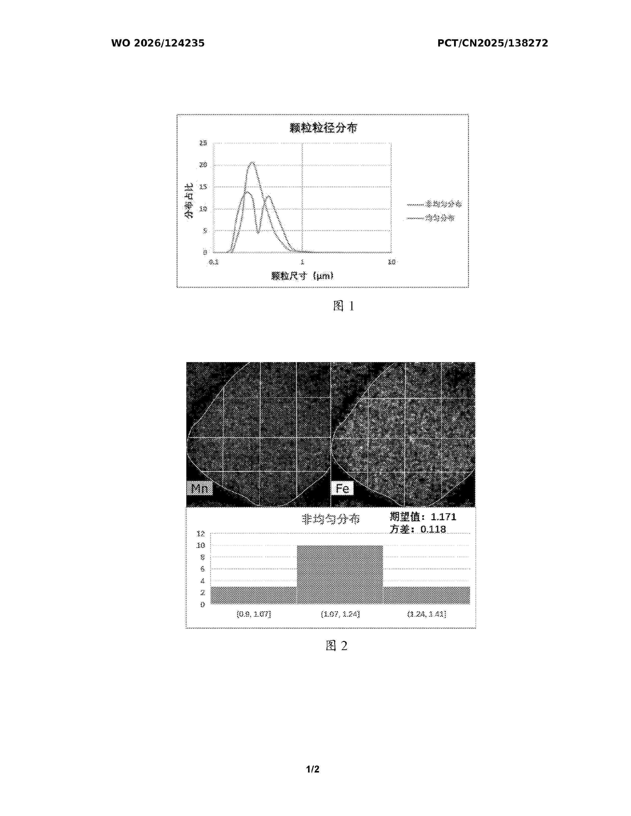
Resumen de: WO2026124235A1
Disclosed in the present application are a positive electrode material, a secondary battery, and an electric device. The positive electrode material exhibits a non-uniform distribution of manganese and iron, which can promote the transformation of a metastable phase thereof into a more stable crystal structure, thereby avoiding Mn dissolution during the cycle process and effectively prolonging the cycle life of a battery. Moreover, the non-uniform particle size distribution of the positive electrode material, in cooperation with large and small particles, can effectively increase the compaction density and the reactive specific surface area of the positive electrode, thereby improving the capacity and charge-discharge rate.
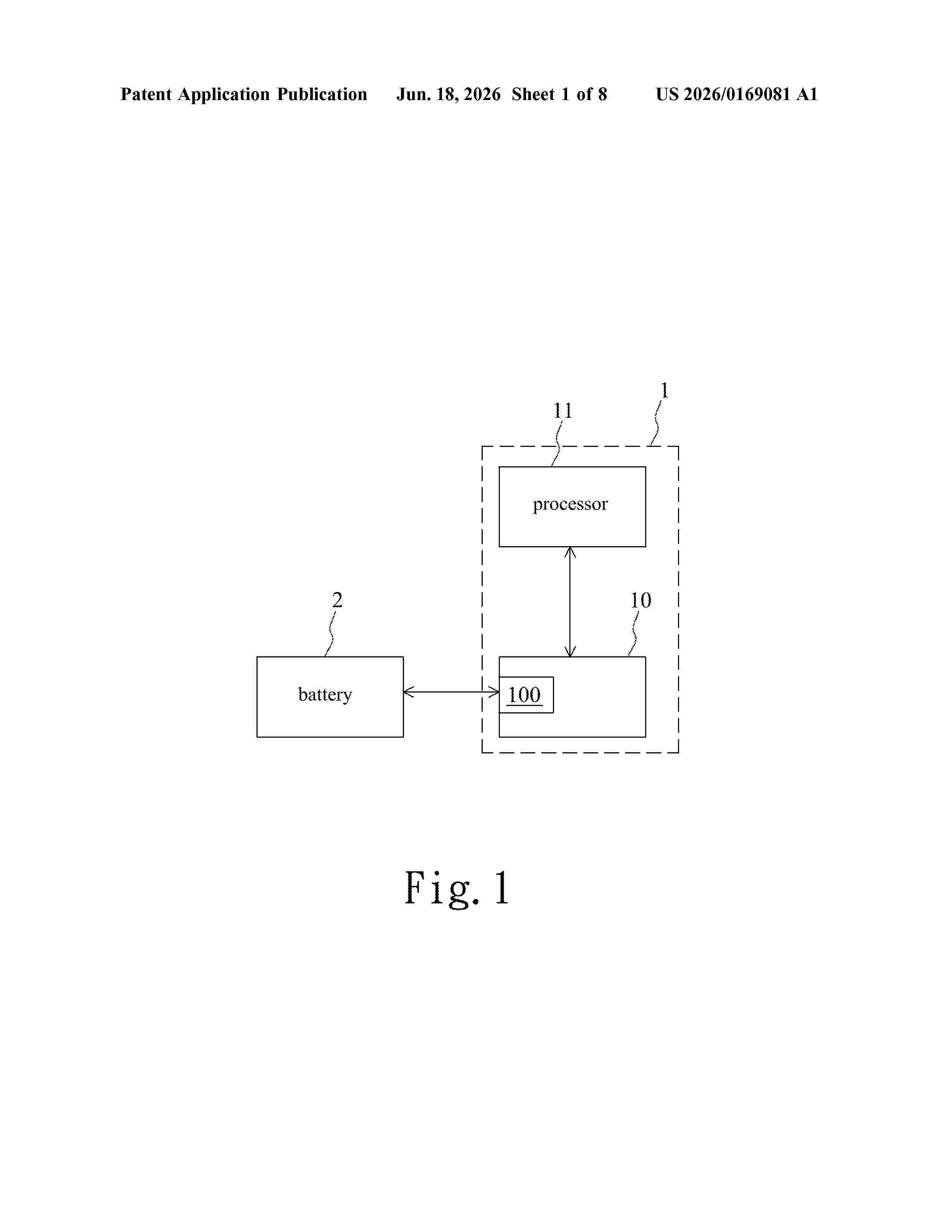
Resumen de: US20260169081A1
0000 In a method for estimating a state of charge, the state of charge of a battery in a charging process is calculated based on the Coulomb integration method until the battery enters a float charging mode. A first curve and a second curve are generated based on the state of charge, a corresponding charging voltage, and a corresponding charging current. After resting the battery, a first present resting open-circuit voltage of the battery is measured. A findable charging voltage and a findable charging current corresponding to the present state of charge of the battery are respectively found from the first curve and the second curve. Finally, a first resting state of charge of the battery is determined based on the present state of charge, the first present resting open-circuit voltage, the findable charging voltage, and the findable charging current.
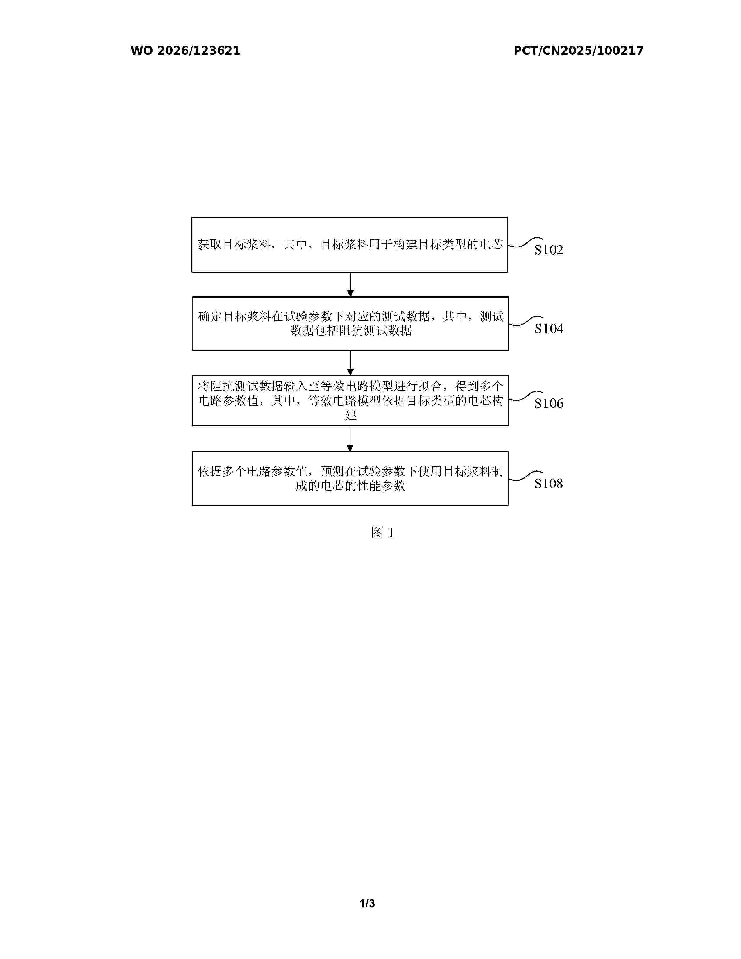
Resumen de: WO2026123621A1
Disclosed in the present application are a battery cell performance parameter prediction method and apparatus, and an electronic device. The method comprises: acquiring a target slurry, wherein the target slurry is used for constructing a battery cell of a target type; determining test data corresponding to the target slurry under experimental parameters, wherein the test data comprises impedance test data; inputting the impedance test data into an equivalent circuit model and performing fitting, so as to obtain a plurality of circuit parameter values, wherein the equivalent circuit model is constructed on the basis of the battery cell of the target type; and on the basis of the plurality of circuit parameter values, predicting performance parameters of a battery cell manufactured using the target slurry under the experimental parameters. The present application solves the technical problem in the related art of it being difficult to conveniently determine battery-cell-related performance parameters on the basis of a slurry.
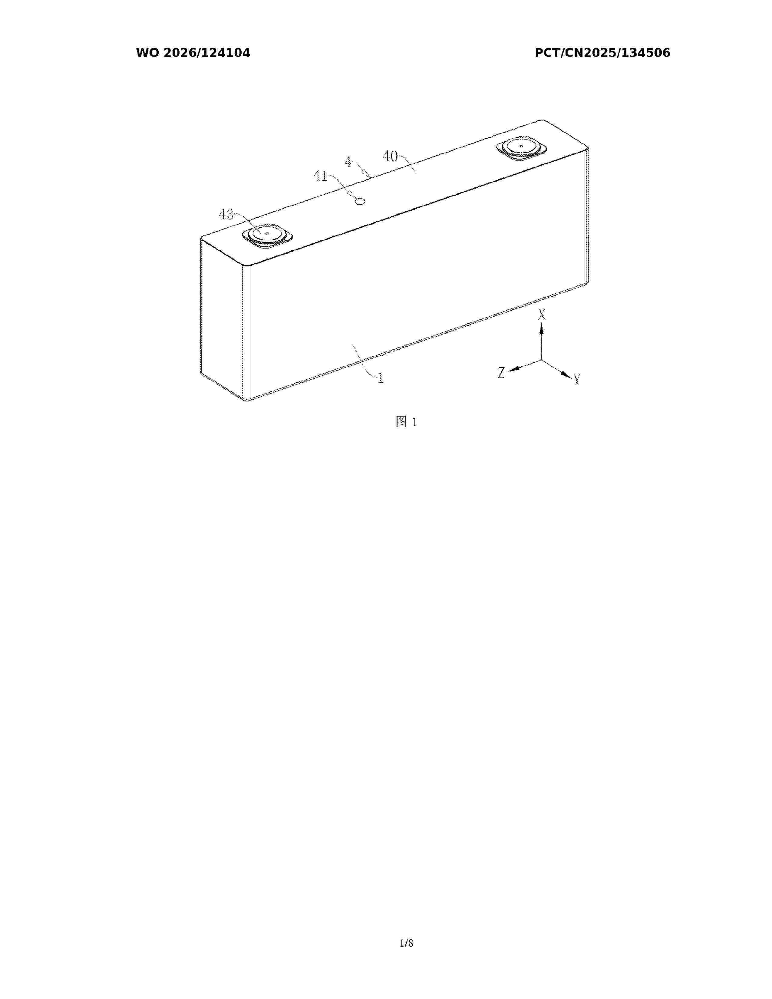
Resumen de: WO2026124104A1
The present application relates to the technical field of batteries, and discloses a battery and a battery pack. The battery comprises: an outer case having an accommodating cavity and an opening in communication with the accommodating cavity; an inner case provided in the accommodating cavity, wherein the inner case has an electrolyte injection cavity, the electrolyte injection cavity is in communication with the opening in a first direction, and electrolyte storage cavities are defined between the inner case and the outer case; an electrode assembly arranged in the electrolyte injection cavity; a cover assembly covering the opening, wherein a first gap is reserved between the cover assembly and the inner case in the first direction, the first gap makes the electrolyte injection cavity in communication with the electrolyte storage cavities, the cover assembly is provided with an electrolyte injection hole, and the electrolyte injection hole is in communication with the electrolyte injection cavity; and unidirectional communication members arranged on the inner case, wherein the unidirectional communication members are configured to allow unidirectional communication from the electrolyte storage cavities to the electrolyte injection cavity when the pressure of the electrolyte storage cavities exceeds a threshold. The present application is conducive to reducing the problem of wrinkles forming on electrode assemblies during charging and discharging of batteries, and prolonging
Nº publicación: US20260171529A1 18/06/2026
Solicitante:
NANJING TECH UNIV [CN]
Nanjing Tech University
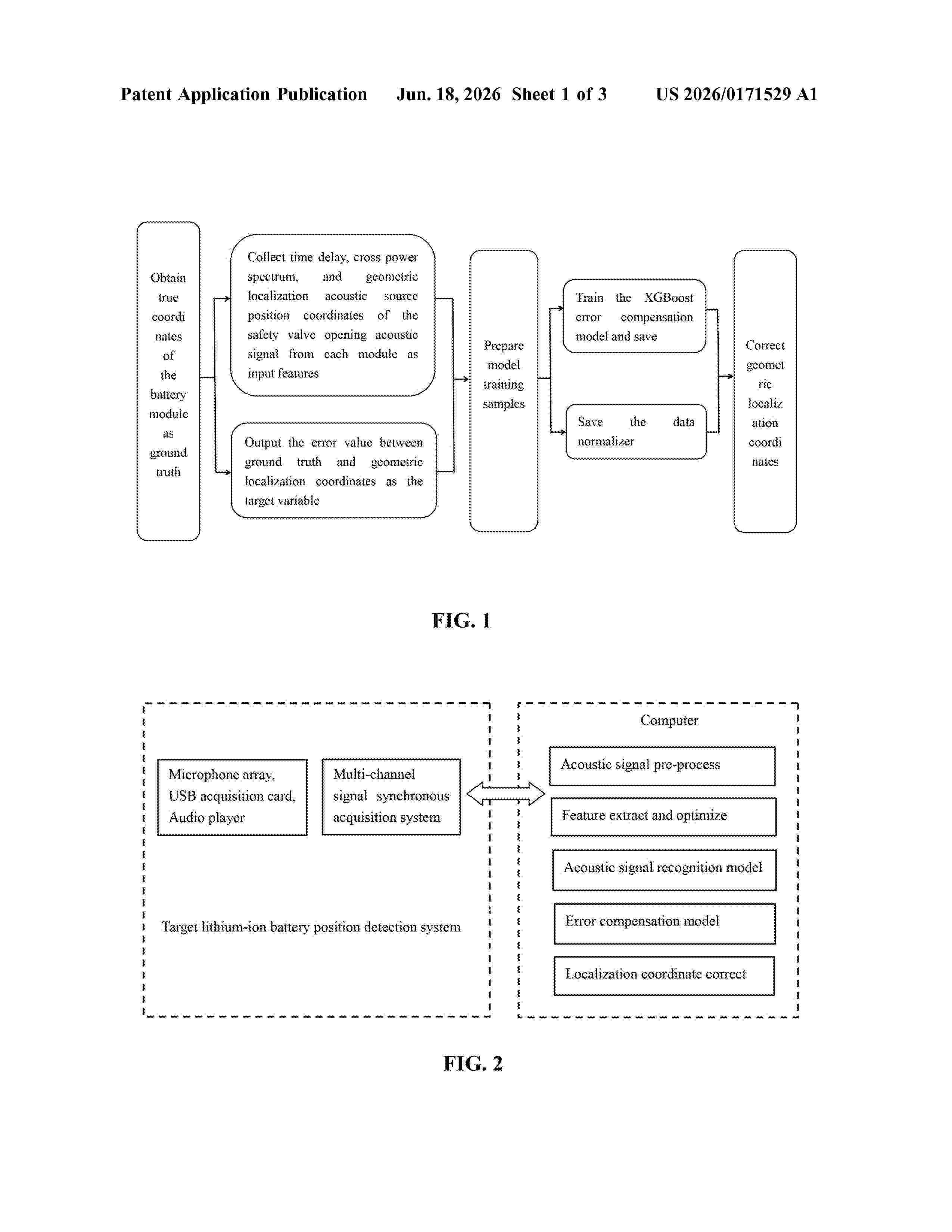
Resumen de: US20260171529A1
The present invention discloses an XGBoost-based lithium-ion battery thermal runaway acoustic source localization error compensation method. Acoustic signals in an energy storage cabin are collected using a fixed microphone array, including time delay data, cross power spectrum data, and acoustic source localization coordinates calculated by a conventional geometric method. The localization error is calculated by comparing the geometric localization coordinates with actual acoustic source position coordinates, and a feature vector is constructed based on the extracted acoustic features. These feature vectors are used to train an XGBoost model. In practical applications, real-time time delay data, cross power spectrum data, and geometric localization coordinates are input into the trained model, and the predicted error value is used to correct the geometric acoustic source localization results, thereby obtaining a more accurate acoustic source position for a thermal runaway lithium-ion battery.
 BOPI
BOPI
 Sede Electrónica