Si deseas distinguir tus productos, servicios o ambos de los de otra empresa, es posible que necesites una marca o nombre comercial. Descubre qué son, en qué consiste su procedimiento de registro y qué implica.

Información sobre los plazos de presentación de solicitudes de transformación de marcas de la Unión Europea en marca nacional española. Más información


Si tienes un nuevo dispositivo, producto o procedimiento que resuelva un problema técnico o tenga una ventaja práctica, existen distintas formas de protegerlo en España y en otros países. Descubre cómo hacerlo.

¿Tu innovación reside en la estética, la ornamentación o la apariencia de tu producto? Protégela mediante un diseño industrial. Descubre qué derechos confiere el registro y cómo realizar la tramitación.

Las indicaciones geográficas protegen el nombre de un producto originario de una zona geográfica, a la cual le debe una determinada calidad, reputación u otra característica. Descubre qué son, en qué consiste su procedimiento de registro y qué beneficios conceden.

Las patentes publicadas en todo el mundo son una valiosa fuente de información científica, técnica y comercial.

Si eres emprendedor/a o una empresa y quieres potenciar y mejorar la rentabilidad de tu negocio protegiendo de forma adecuada los activos intangibles de tu organización, en este espacio encontrarás lo necesario.


 1422
resultados
1422
resultados
 Última actualización
28/06/2026 [07:11:00]
Última actualización
28/06/2026 [07:11:00]


 Resultados 675 a 700 de 1422

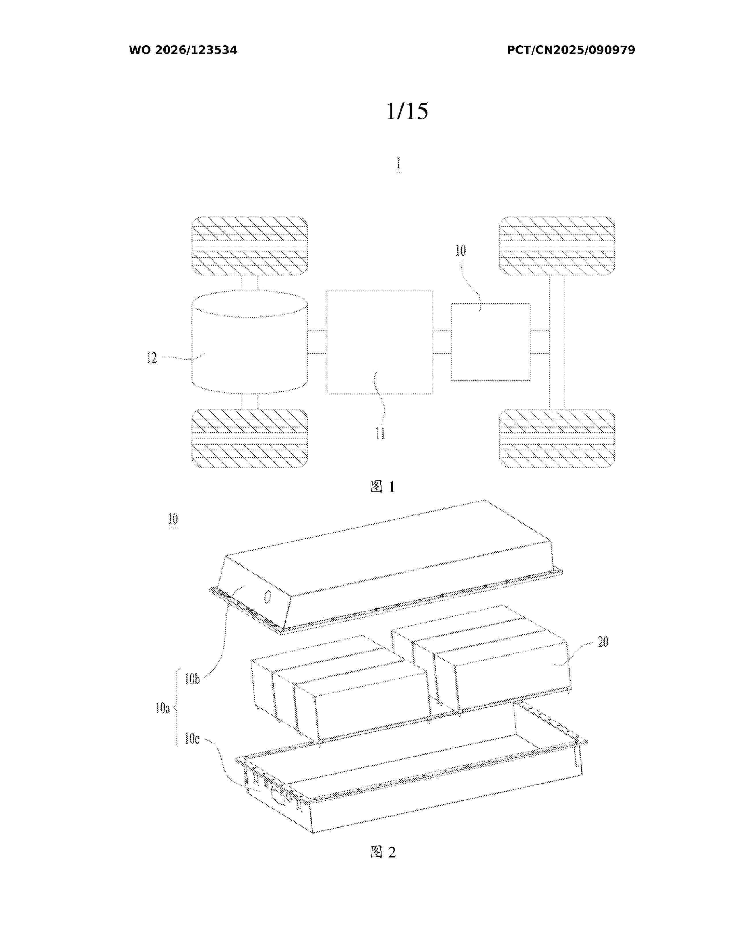
Resumen de: WO2026123534A1
The present application provides an electrode assembly, a battery cell, a battery apparatus, an electrical apparatus, and a manufacturing method. The electrode assembly comprises a first electrode sheet, a first solid-state electrolyte layer, a second electrode sheet, and an insulating layer. The first electrode sheet comprises a first main body portion and a first tab. The first main body portion is provided with the first solid-state electrolyte layer. The first electrode sheet and the second electrode sheet have opposite polarities. The second electrode sheet comprises a second main body portion. The area of the second main body portion is greater than the area of the first main body portion. The first solid-state electrolyte layer is located between the first main body portion and the second main body portion. The second main body portion comprises a thinned-edge portion extending in a circumferential direction. The insulating layer is disposed at the thinned-edge portion. The insulating layer has a notch. The first tab is disposed corresponding to the notch.

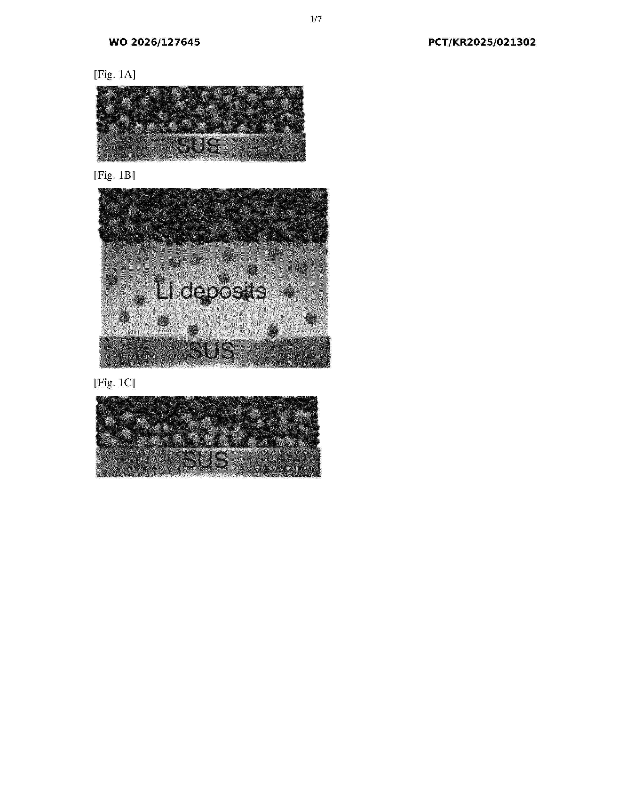
Resumen de: WO2026127645A1
A nanocomposite interlayer including a carbonaceous material, nanoparticles including metals or metalloids, at least one polymer binder, and a pH adjusting agent is provided. The carbonaceous material includes amorphous carbon, graphite, graphene, reduced graphene oxide, carbon nanotube, or combinations thereof. An anodeless battery including a positive electrode, a negative electrode current collector, the nanocomposite interlayer on the negative electrode current collector, and an electrolyte, and a method of operating the anodeless battery is also provided.
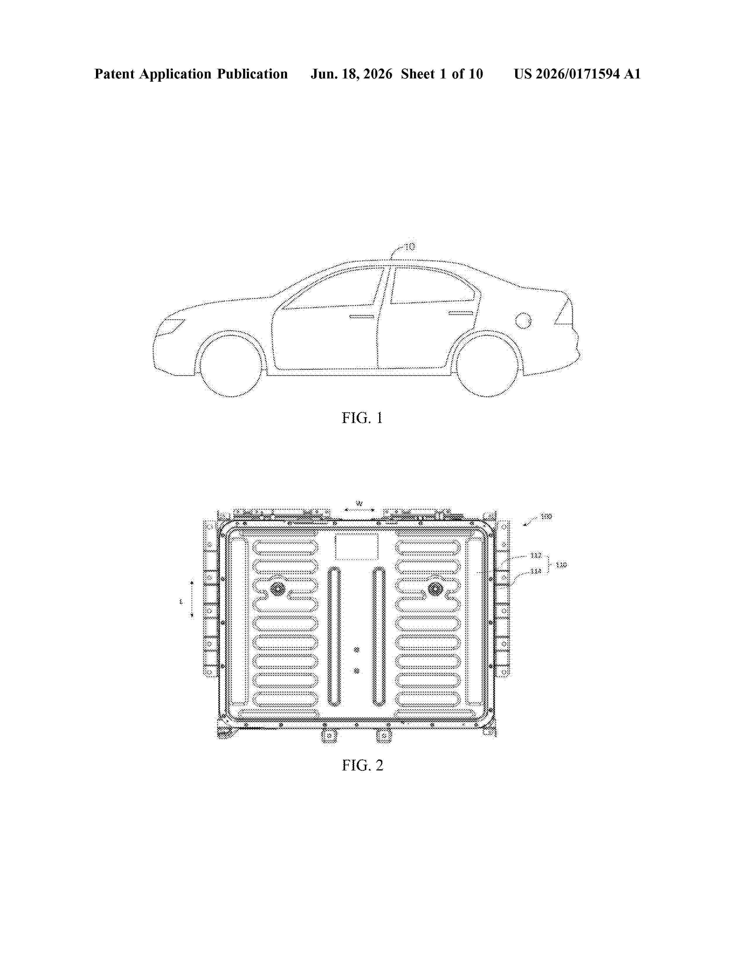
Resumen de: US20260171594A1
0000 A battery pack may include a first compartment accommodating a battery unit. The first compartment includes a first side wall having a first opening, a first flexible thermal insulation layer covering the first opening and having a first weakened structure opposite to the first opening, and a second flexible thermal insulation layer connected to the first flexible thermal insulation layer and aligned with the first opening. The first flexible thermal insulation layer is located between the second flexible thermal insulation layer and the first side wall. The proposed battery pack can provide adaptive isolation measures for battery units under different working conditions, while allowing the discharging of gas, and can at least to some extent reduce the ability of the exhaust gas from the battery unit from influencing other battery units inside the battery pack.
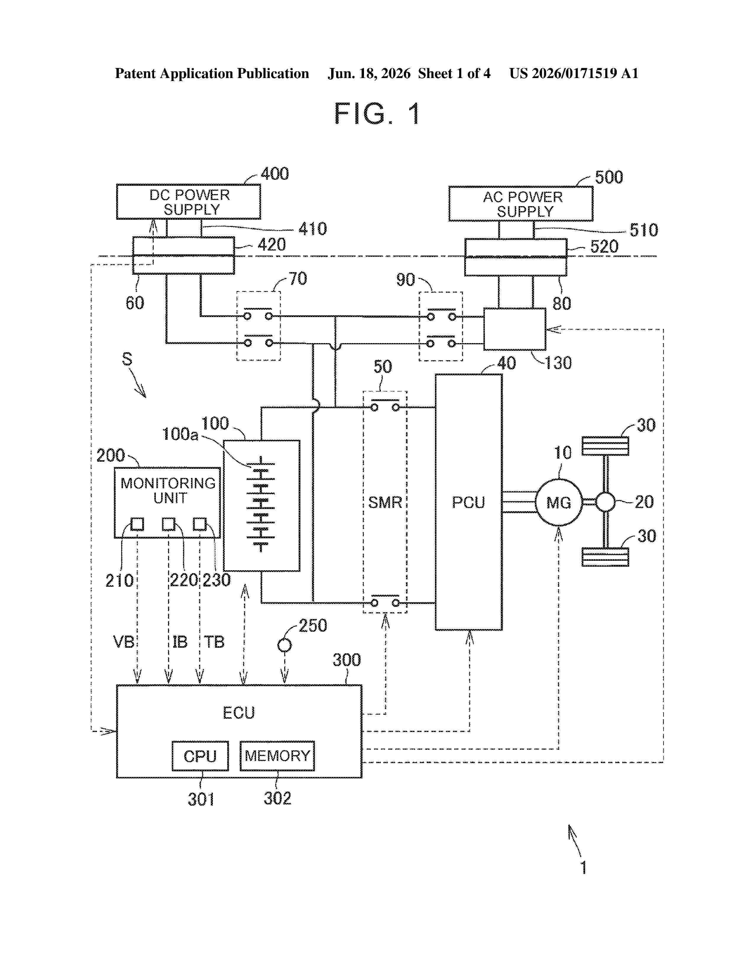
Resumen de: US20260171519A1
An ECU acquires the SOC, SOH, and degradation time. An anode degradation coefficient is calculated from the SOH and an effective temperature, and a time degradation coefficient is calculated from the degradation time and the effective temperature. The smaller of the anode degradation coefficient and the time degradation coefficient is calculated as an overall degradation coefficient, and an initial input current limit value is calculated from the SOC and the effective temperature. An input current limit value is calculated by multiplying the initial input current limit value by the overall degradation coefficient. The input current of the battery is controlled so as not to exceed the input current limit value. When an anode degradation factor (= SOH × anode resistance increase rate) is greater than 1, the anode degradation coefficient is set to the reciprocal of the anode degradation factor.
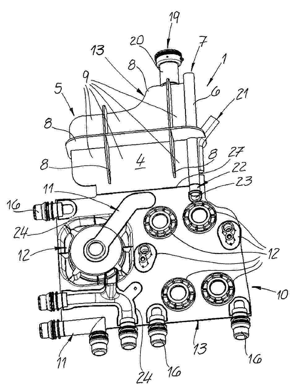
Resumen de: DE102024137453A1
Ein Behälter (1) für ein Modul (2) eines Temperiermittelkreislaufs weist eine Behälterwand (3) auf. Die Behälterwand (3) schließt ein mit dem Temperiermittel befüllbares Behälterlumen (4) ein. Der Behälter (1) weist ein Innenelement (5) auf, wobei das Innenelement (5) von der Behälterwand (3) wenigstens teilweise umschlossen wird bzw. in den Behälterlumen (4) angeordnet ist. Ein Modul (2) für einen Temperiermittelkreislauf umfasst einen bzw. den Behälter (1) und einen Träger (10). Der Behälter (1) weist eine Behälterwand (3) auf, wobei die Behälterwand (3) ein mit dem Temperiermittel befüllbares Behälterlumen (4) einschließt. Der Träger (10) weist wenigstens einen Kanal (11) und wenigstens eine Aufnahme (12) zur Anordnung wenigstens einer Fluidkomponente (17, 25) auf. Der Träger (10) umfasst ein Mittelteil (13), ein erstes Seitenteil (14) und ein zweites Seitenteil (15). Der Behälter (1) weist das Mittelteil (13), das erste Seitenteil (14) und/oder das zweite Seitenteil (15) auf.
Resumen de: US20260171589A1
A battery pack includes a first battery unit, a second battery unit, a plate member, a thermal insulation plate, and an air flow channel. The plate member extends between the first battery unit and the second battery unit in a first direction. The thermal insulation plate is disposed between the plate member and the first battery unit. The first battery unit has a first vent hole facing the plate member. The air flow channel formed between the plate member and the thermal insulation plate.
Resumen de: US20260171546A1
0000 A manufacturing method for a heat management system includes reducing a pressure of air in a first channel and a second channel included in the heat management system from a supply apparatus included in the heat management system in a state where no coolant is flowing through the first channel and the second channel. The first channel and the second channel are configured to flow the coolant inside. The manufacturing method includes adding the coolant to the supply apparatus such that the supply apparatus simultaneously supplies the coolant to both the first channel and the second channel that are reduced in pressure. A pressure higher than atmospheric pressure is applied to the coolant.
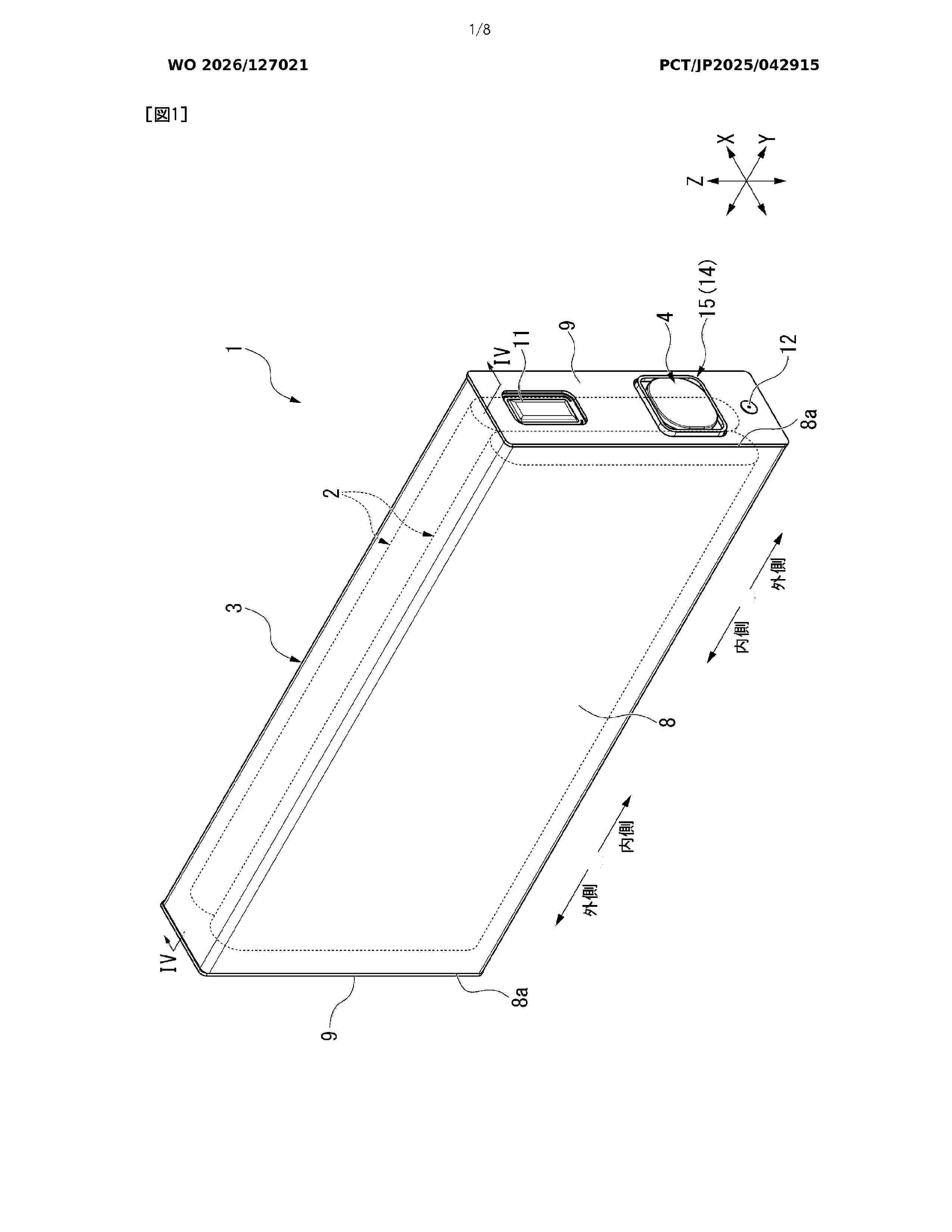
Resumen de: WO2026127021A1
Provided is a power storage element comprising: a cylindrical case body in which openings are formed at both ends; an electrode body housed in the case body; a spacer disposed between the case body and the electrode body; and a tape wound around the electrode body and the spacer. The spacer has a protrusion protruding from an outer edge of the tape when viewed from a first direction from one opening to the other opening, and the protrusion is provided between the tape and the one opening in the first direction.
Resumen de: WO2026125215A1
The present invention relates to a positive electrode comprising a positive electrode active material and a sulfide solid electrolyte with a low particle size, and additionally a conductive agent and a binder. The present invention further relates to a method for manufacturing said positive electrode and a battery comprising said positive electrode.
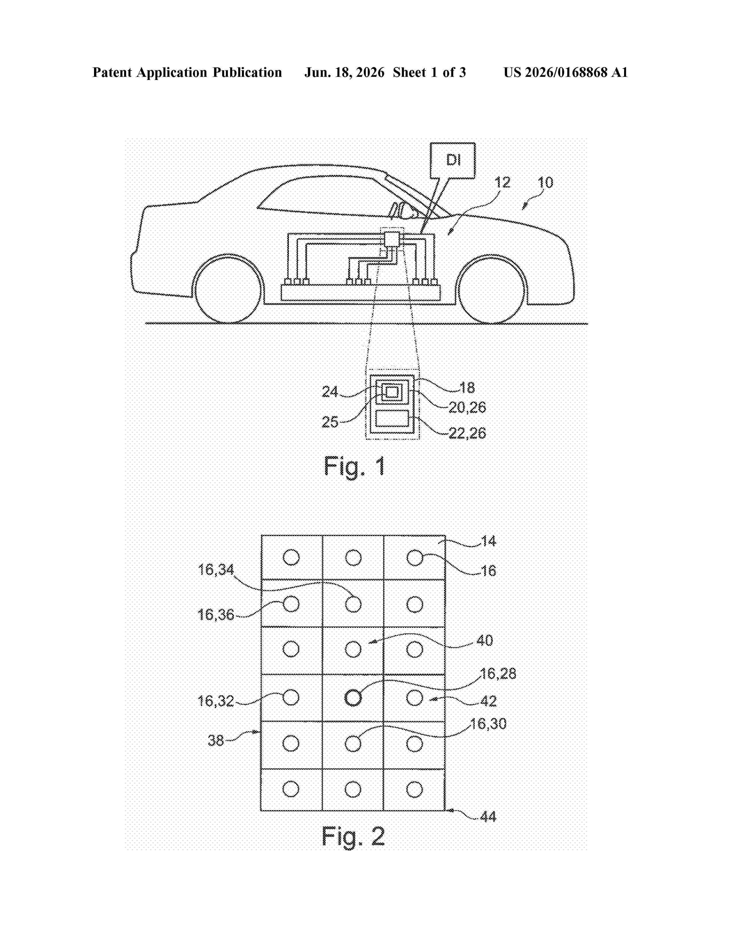
Resumen de: US20260168868A1
0000 A method for detecting a faulty temperature sensor out of a plurality of temperature sensors in a battery assembly for a vehicle. Each of the plurality of temperature sensors is arranged in an associated location. The method includes obtaining a plurality of data items (DI), where each data item (DI) is associated with a temperature sensor out of the plurality of temperature sensors and where each data item (DI) is indicative of a temperature and a location of the associated temperature sensor. The method further includes comparing the data items (DI) with respect to the associated temperatures and/or the associated locations. Moreover, the method includes determining, based on the comparing, one or more outlier data items (DI) out of the plurality of data items (DI) and inferring the one or more temperature sensors associated with the one or more outlier data items (DI) to be faulty.
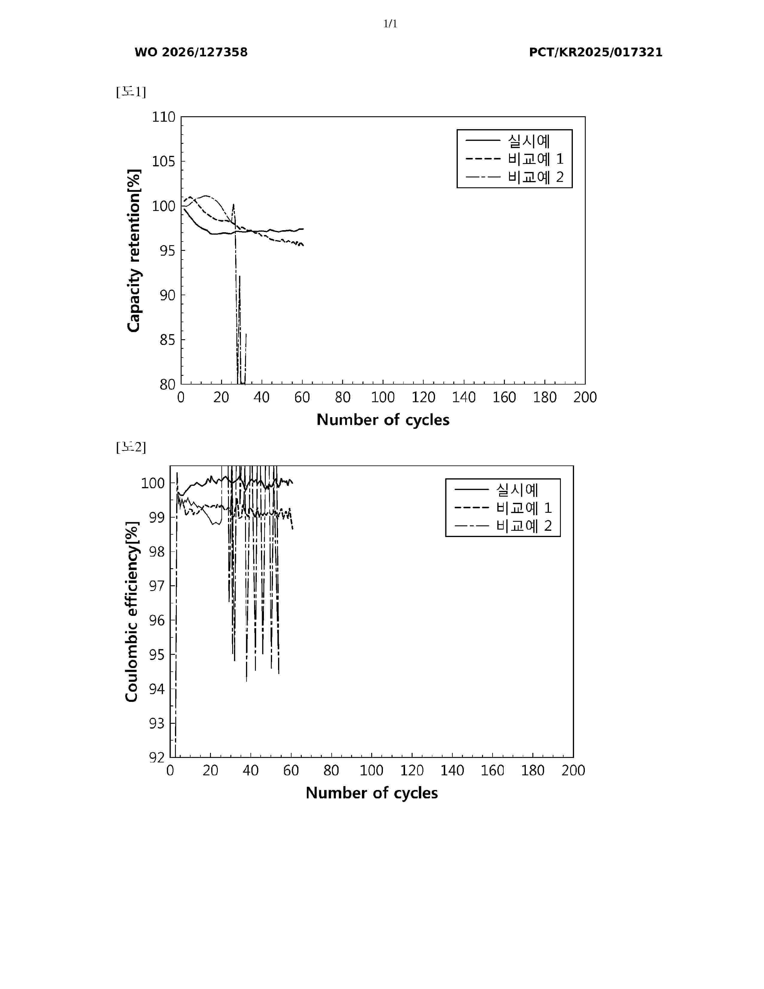
Resumen de: WO2026127358A1
The present invention provides a coating layer of a novel composition on a lithium metal negative electrode for use in a lithium secondary battery, thereby achieving the effect of improving the coulombic efficiency and lifespan of a lithium secondary battery using the lithium metal negative electrode. A coating layer of a negative electrode for a lithium secondary battery according to an aspect of the present invention is characterized by including fluorine and boron.
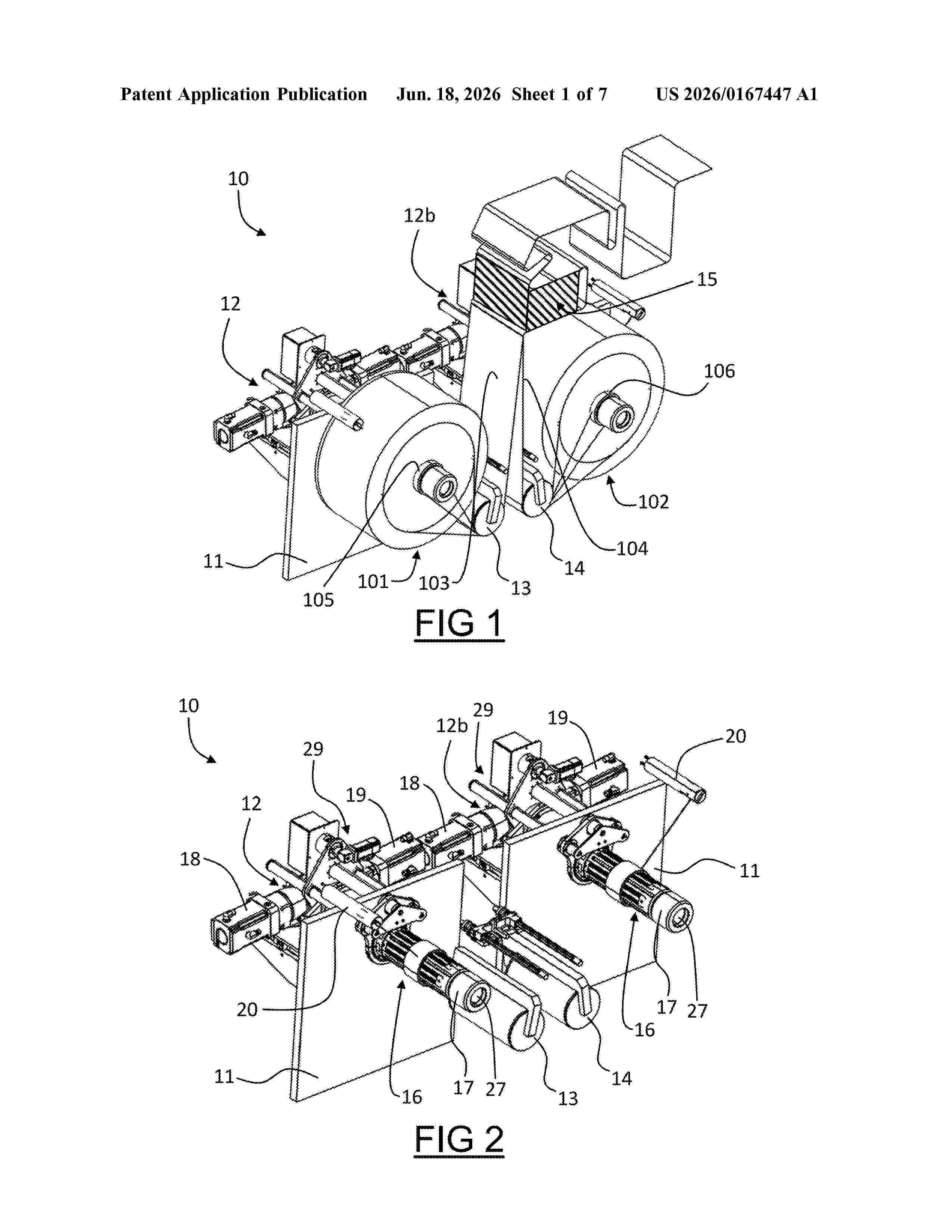
Resumen de: US20260167447A1
An apparatus for changing reels in electrochemical cell production, comprising: a frame; at least one mandrel supported by the frame and rotatable about an axis of rotation, the at least one mandrel comprising a shaft configured to accommodate a hollow core of a reel, the shaft comprising a loading end configured to thread the hollow core of the reel; an extraction system configured to translate at least the shaft in a longitudinal direction with respect to the axis of rotation, the shaft being movable between a working position and a loading/unloading position, the loading end being at a greater distance from the frame in the loading/unloading position than in the working position.A method for changing reels in electrochemical cell production.An electrochemical cell production method.
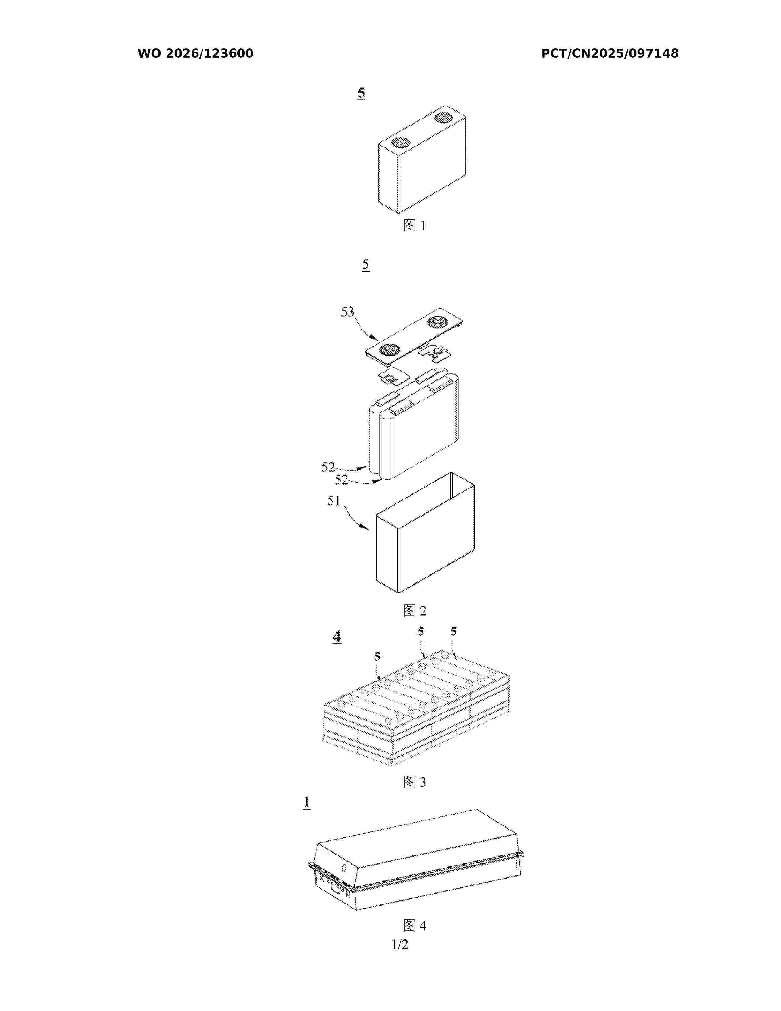
Resumen de: WO2026123600A1
The present application provides a lithium-ion battery device and an electric device. The lithium-ion battery device comprises a battery cell and a battery management system for managing the battery cell. The battery cell comprises a positive electrode sheet and an electrolyte, wherein the positive electrode sheet comprises a positive electrode active material, the positive electrode active material comprises a nickel-containing lithium transition metal oxide, and in the nickel-containing lithium transition metal oxide, the molar ratio of nickel to metal elements other than lithium is 0.45:1 to 0.95:1; and the electrolyte comprises an organic solvent, the organic solvent comprises ethylene carbonate, and the weight content of the ethylene carbonate in the organic solvent is less than or equal to 20%. The charge cut-off voltage of the lithium-ion battery device as set in the battery management system is greater than 4.3 V.
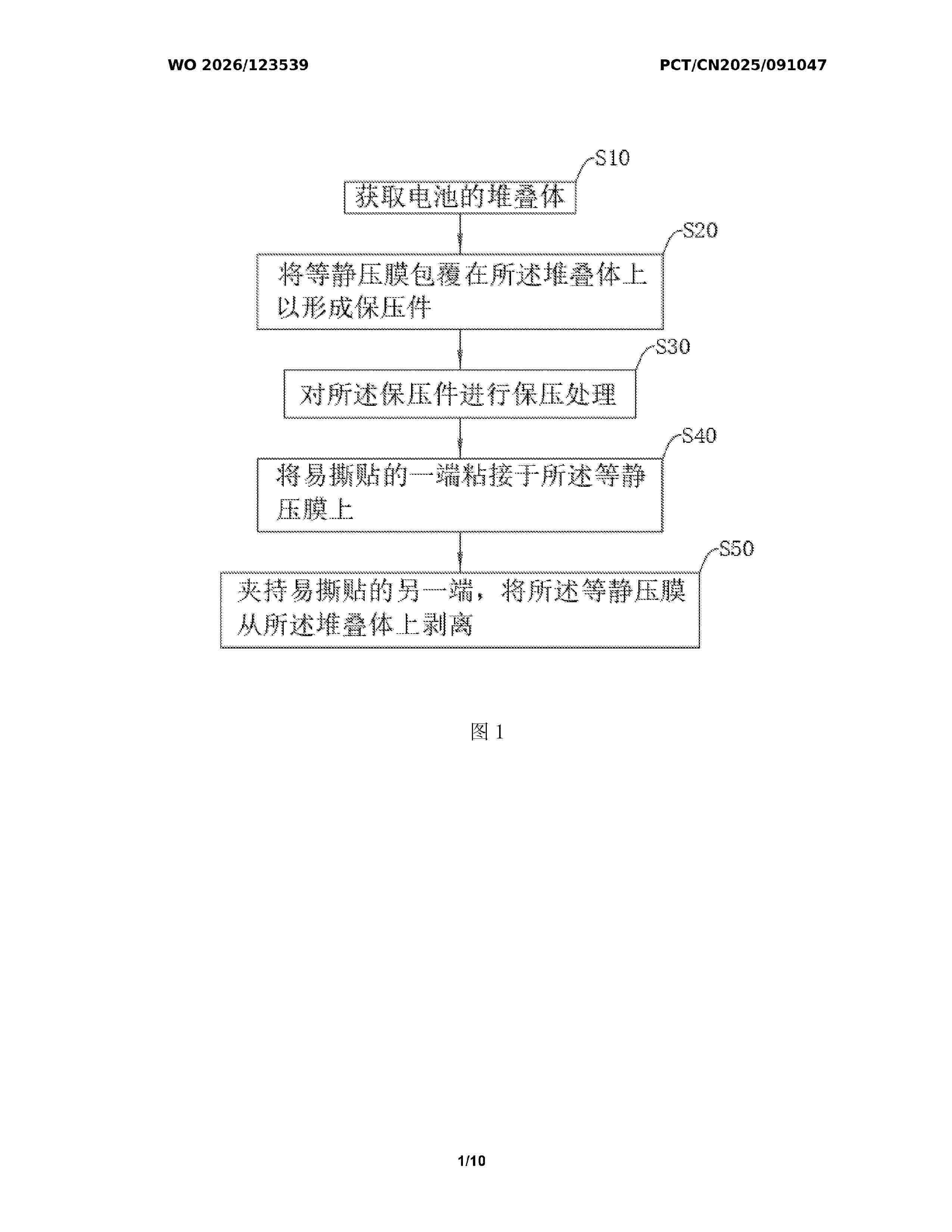
Resumen de: WO2026123539A1
The present application relates to a preparation process and a solid-state battery. The preparation process comprises: obtaining a battery stack; wrapping an isostatic pressing film around the stack to form a pressure-retaining member; performing a pressure-retaining treatment on the pressure-retaining member; adhering one end of a peel-off tape to the isostatic pressing film; and clamping the other end of the peel-off tape to peel the isostatic pressing film off of the stack. The preparation process and the solid-state battery according to the embodiments of the present application have the advantage of a higher production efficiency.
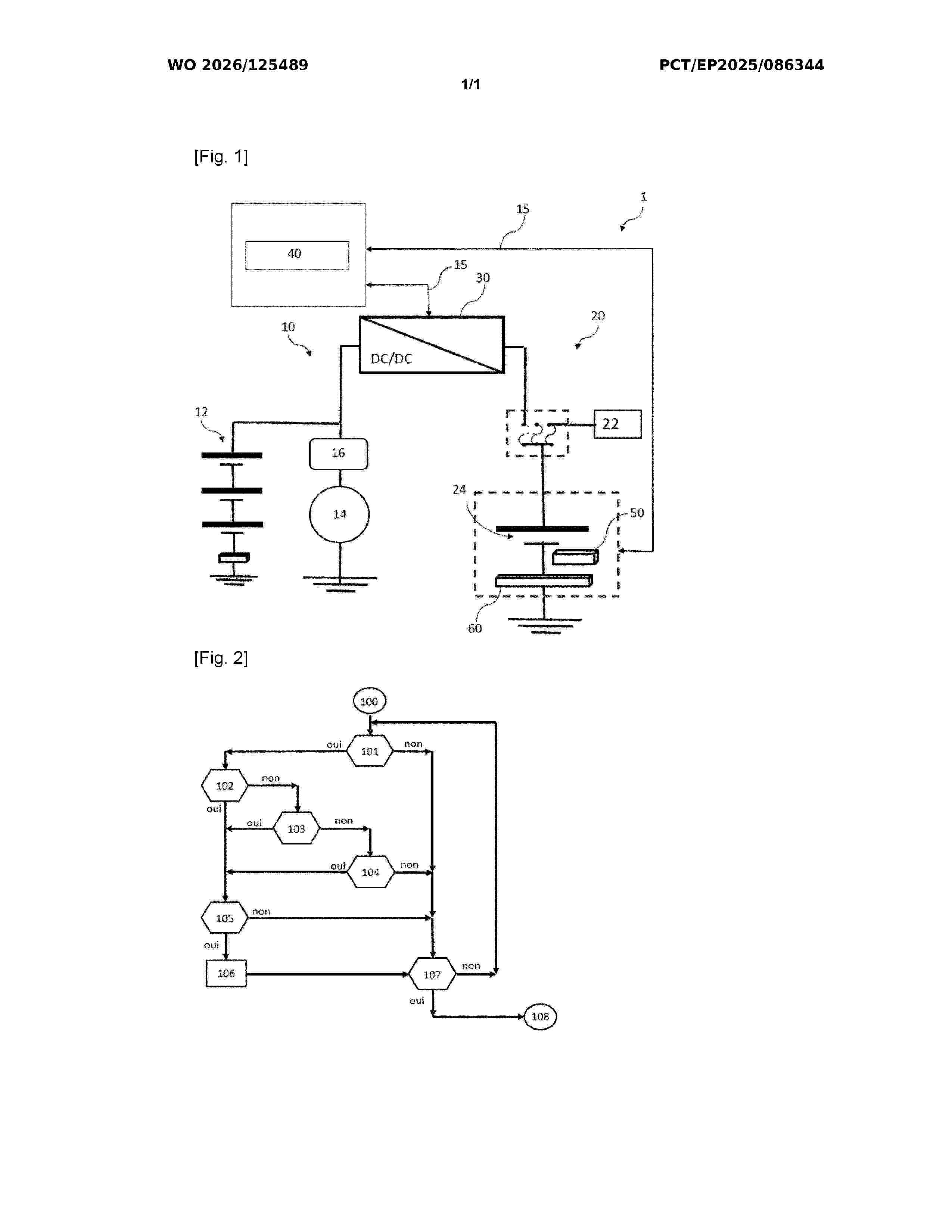
Resumen de: WO2026125489A1
Disclosed is a method for managing the charge level of a low-voltage battery (24) of an electric motor vehicle comprising a high-voltage battery module (12), the method being characterised in that it comprises: - a step (100) of initiating a rest phase of the vehicle and of starting a monitoring time period; - a step (101) of assessing a condition indicating whether the monitoring time period has elapsed; - when said time period has elapsed, one or more steps (102, 103, 104) of measuring a parameter of the low-voltage battery; - if at least one parameter exceeds a threshold, a verification step (105) in which the monitoring device (50) verifies whether the threshold continues to be exceeded for a predetermined length of time; - if the threshold continues to be exceeded for said length of time, a step (106) of recharging the low-voltage battery (24) by means of the at least one high-voltage battery module (12).
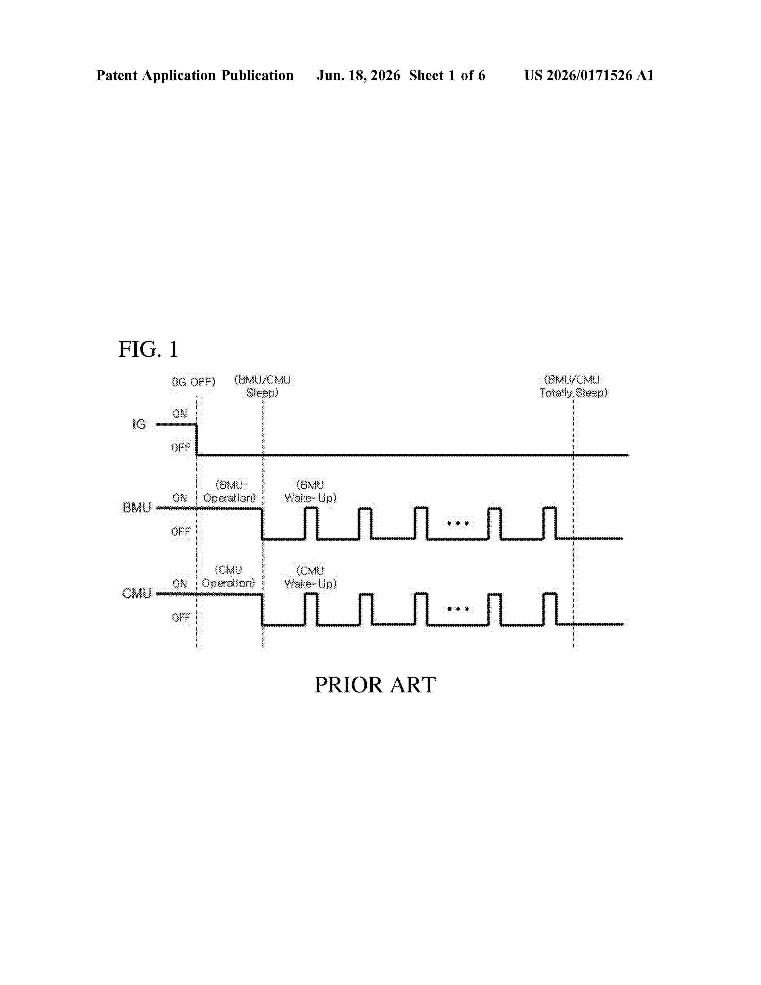
Resumen de: US20260171526A1
A wireless battery management system includes at least one cell monitoring unit (CMU) configured to monitor a status of at least one battery module including a plurality of battery cells, and a battery management unit (BMU) configured to manage the at least one CMU through wireless communication with the at least one CMU. The at least one CMU continuously monitors the status of the plurality of battery cells included in the battery module, and upon or based on detecting or determining an abnormal state in at least one battery cell, notifies the BMU of the abnormal state of the battery cell. Upon or based on receiving notification of the abnormal state of the battery cell from the CMU, the BMU transitions from a sleep mode to an active mode, and responds to the abnormal state of the battery cell.
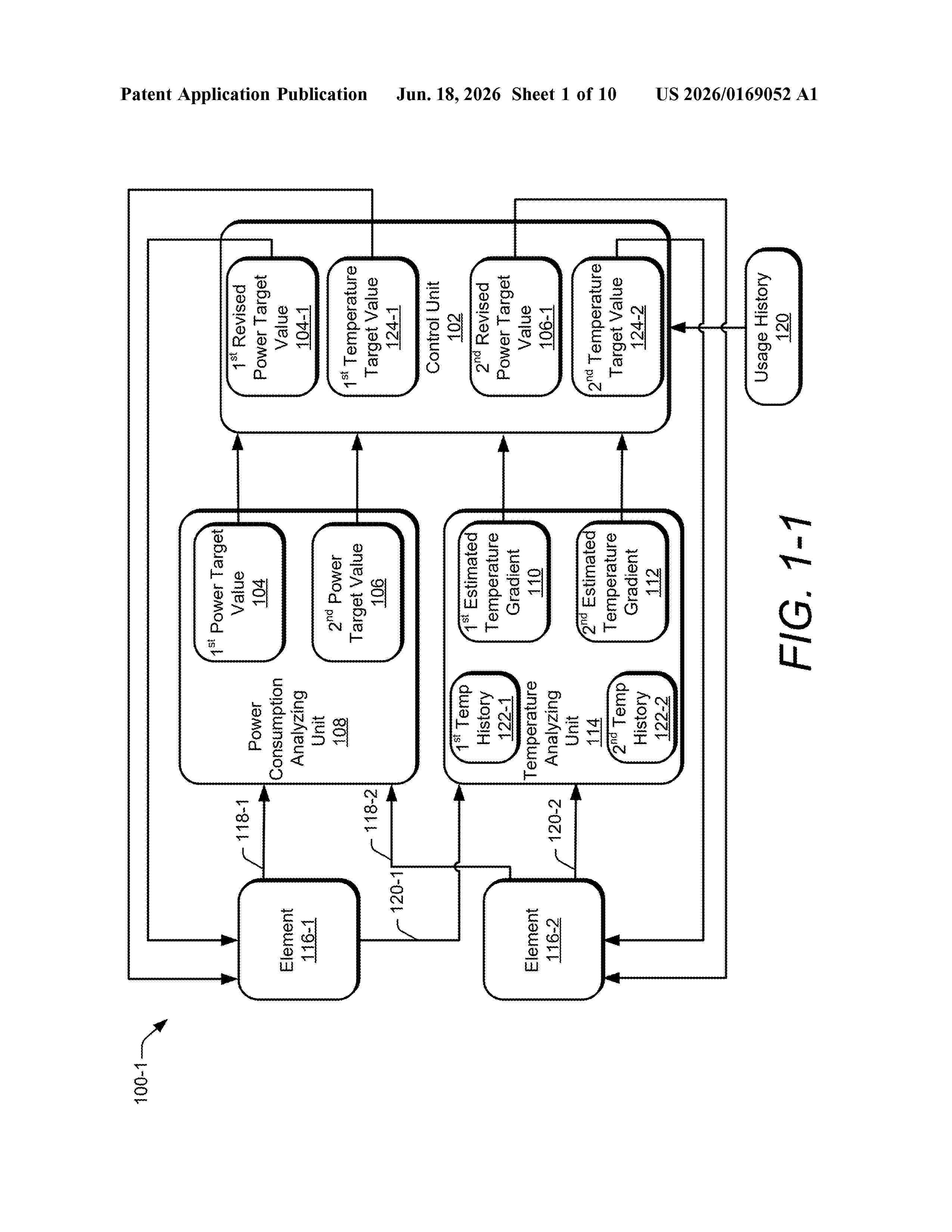
Resumen de: US20260169052A1
0000 Aspects of workload-aware control architectures for semiconductor devices are disclosed. For example, a control unit receives power target values from a power consumption analyzing unit and estimated temperature gradients from a temperature analyzing unit each coupled with an element of a semiconductor device. The power consumption analyzing unit determines the power target values based on power consumption of the element and the temperature analyzing unit determines the estimated temperature gradients based on temperature in combination with a temperature history of the element. The control unit generates revised power targets and temperature targets based on the received power target values, the estimated temperature gradients, and a usage history. The usage history may include a current workload and/or a workload history of the element and may be provided by a machine-learned model or artificial intelligence. The revised power target and temperature target values are dynamically generated to optimize performance.
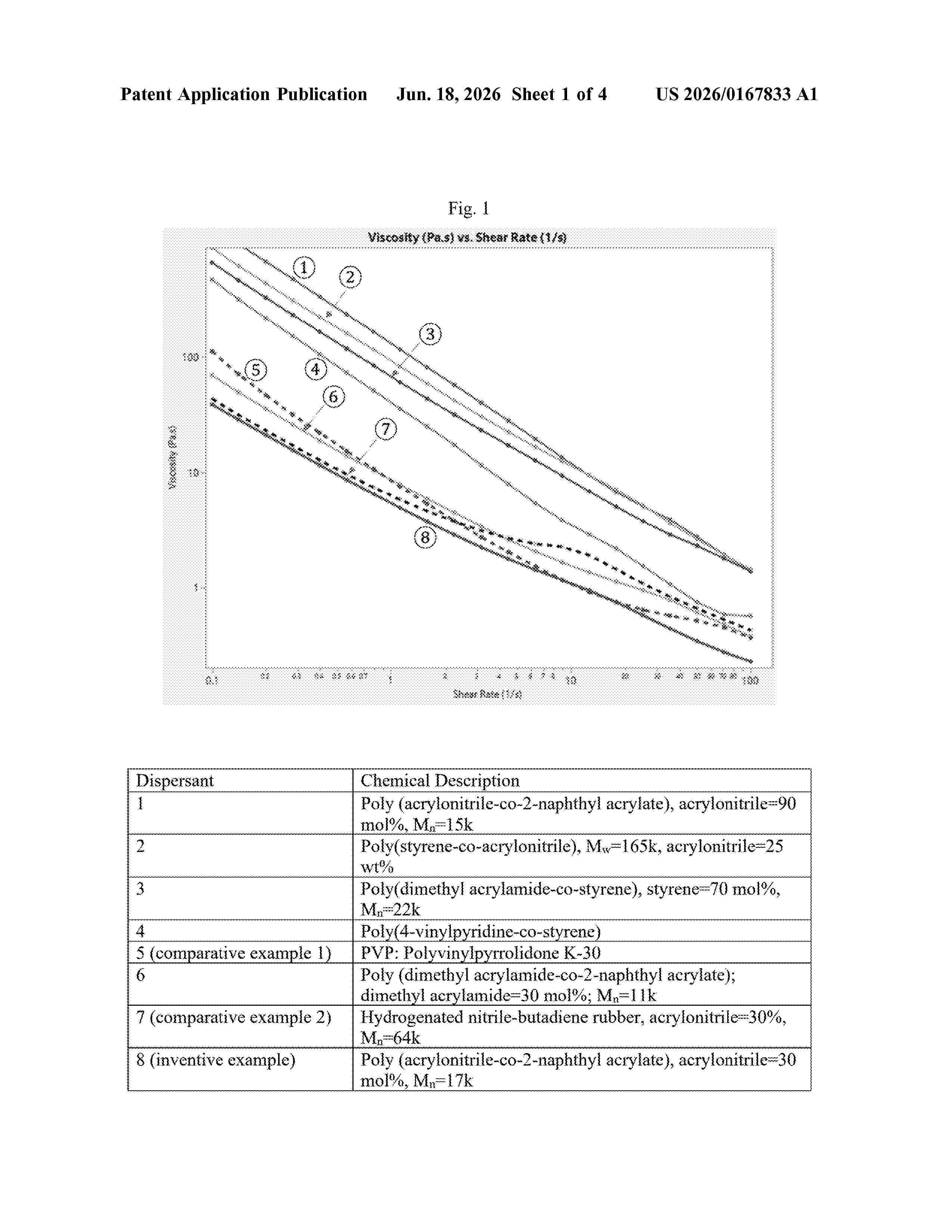
Resumen de: US20260167833A1
Copolymers having structural units of the residue of a substituted or unsubstituted, unsaturated organic nitrile monomer present in an amount from about 1 wt % to about 55 wt %, based on the total weight of the copolymer; and structural units of the residue of a substituted or unsubstituted, unsaturated, conjugated aromatic monomer selected from a conjugated aromatic ester monomer, a conjugated aromatic ether monomer, a conjugated aromatic amide monomer, a conjugated aromatic alkylene monomer, and combinations thereof, present in an amount from about 45 wt % to about 99 wt %, based on the total weight of the copolymer. Homopolymers and copolymers that are useful as dispersants. Dispersant concentrates, conductive carbon dispersions, electrode slurry compositions, positive electrodes, and electrical storage devices, using the dispersants. The dispersants are used in conductive carbon dispersions and electrode slurry compositions to achieve low viscosity at high solids content.
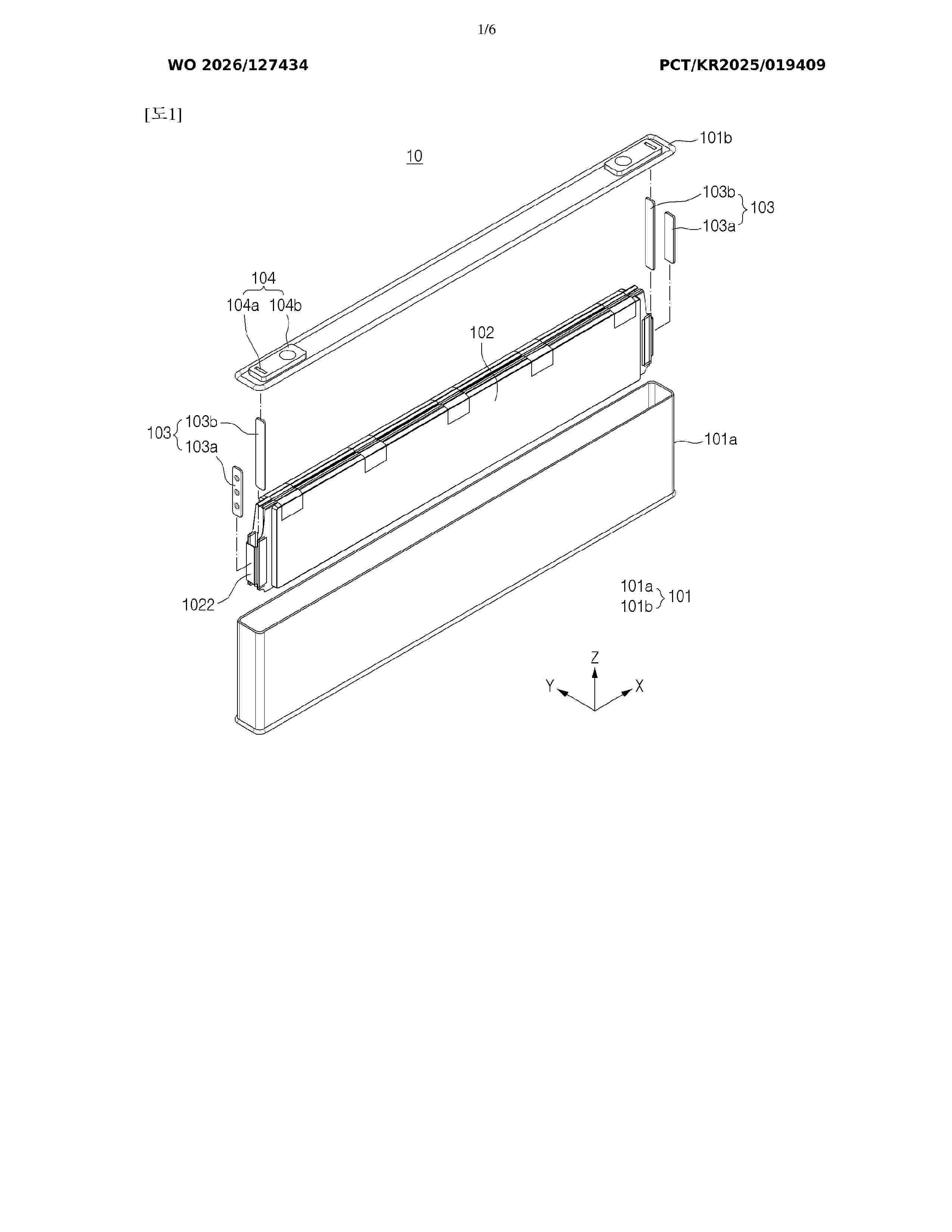
Resumen de: WO2026127434A1
The present invention provides a battery cell unit comprising: an outer case having terminal parts; a battery cell assembly accommodated in the outer case and comprising a plurality of pouch battery cells; and busbars electrically connected to the respective terminal parts of the outer case, and each busbar being coupled to electrode leads of the same polarity that are provided on the plurality of pouch battery cells.
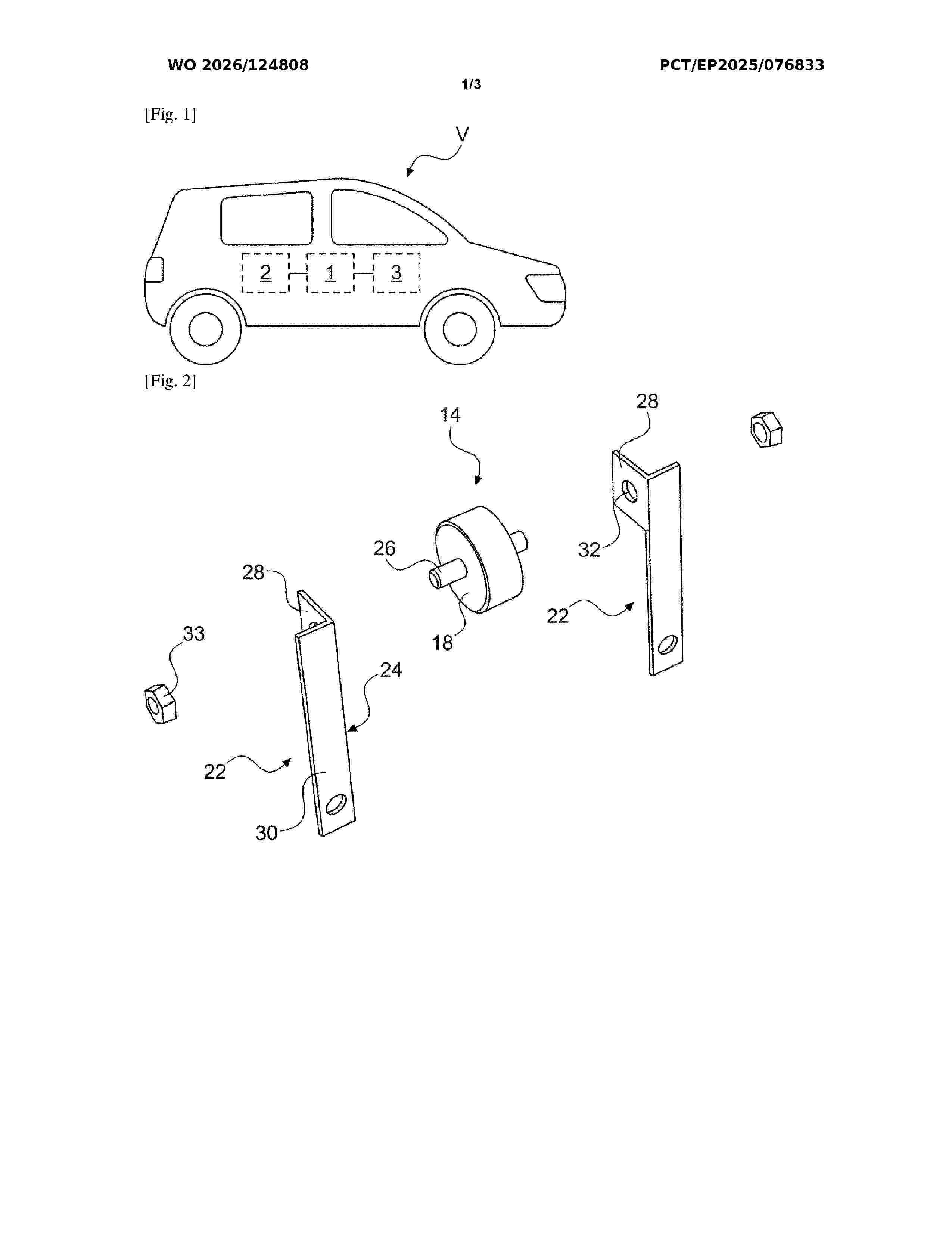
Resumen de: WO2026124808A1
The invention relates to a thermal conduction device, in particular for a motor vehicle, which device is configured to form a thermal bridge between electrical connection terminals (10a, 10b), provided at distinct electrical potentials, of the same electrical member (12) forming a heat source, the device comprising a first housing (14) configured to form an electrical insulation between the connection terminals (10a, 10b), the first housing (14) receiving a dielectric fluid so as to establish a heat exchange between the connection terminals (10a, 10b) through the fluid, the first housing (14) comprising an electrically insulating armature (16) and closing walls (18), the closing walls (18) being thermally conductive and arranged on either side of the armature (16) so as to be electrically insulated from one another, the closing walls (16) being configured such that they are capable of exchanging heat with the connection terminals (10a, 10b).
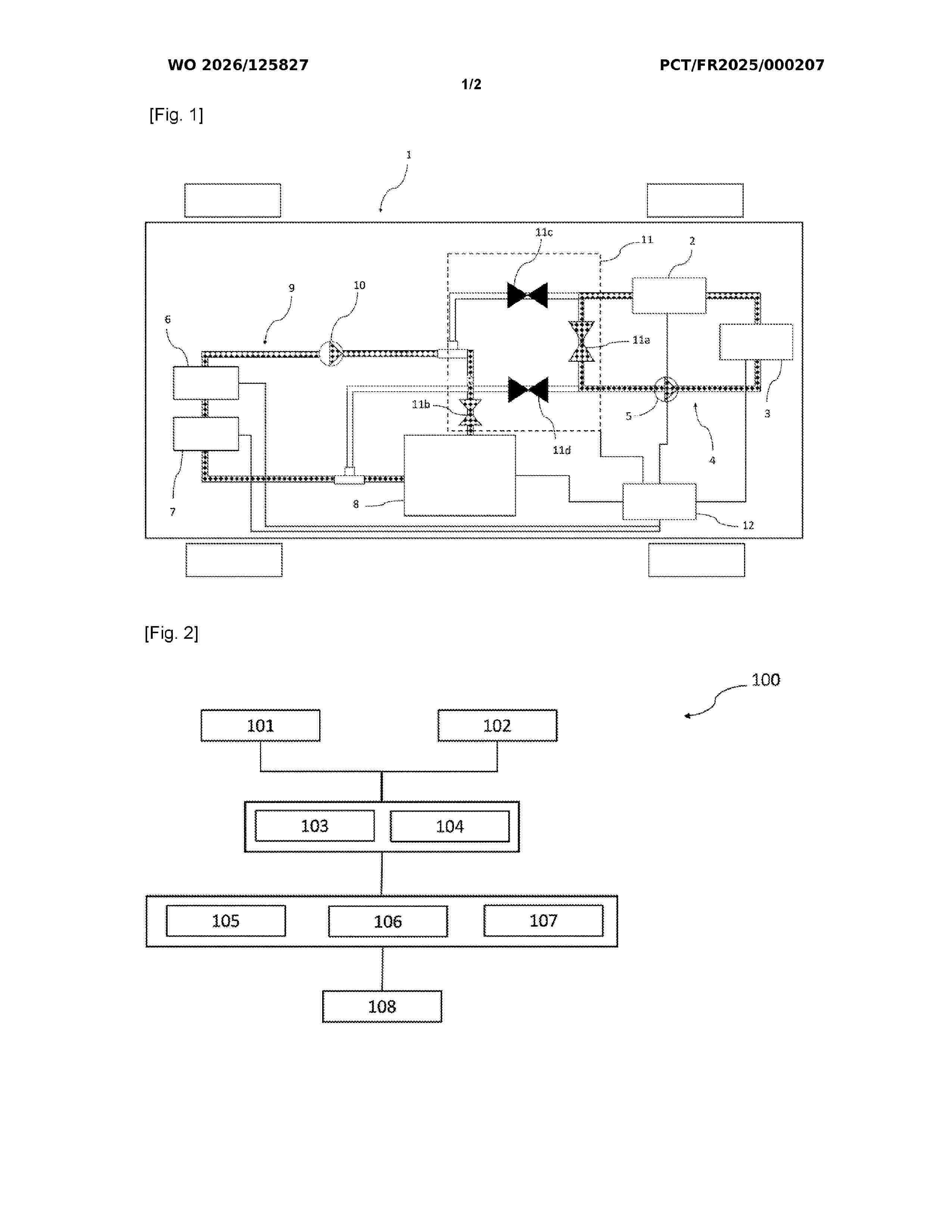
Resumen de: WO2026125827A1
One aspect of the invention relates to a method (100) for cooling a traction battery of a vehicle, the vehicle comprising a first cooling circuit for the battery and a second cooling circuit for a traction electric machine, wherein, following detection of thermal runaway of the battery, the method (100) carries out the steps of: fluidically disconnecting (101) the first and second circuits; deactivating (102) operation of the traction battery and of the traction electric machine; activating (103) operation of a first pump of the first circuit and of a second pump of the second circuit; fluidically connecting (105) the first and second circuits when: the temperature of the first circuit increases until reaching a first temperature threshold; or the temperature of the second circuit decreases until reaching a second temperature threshold.
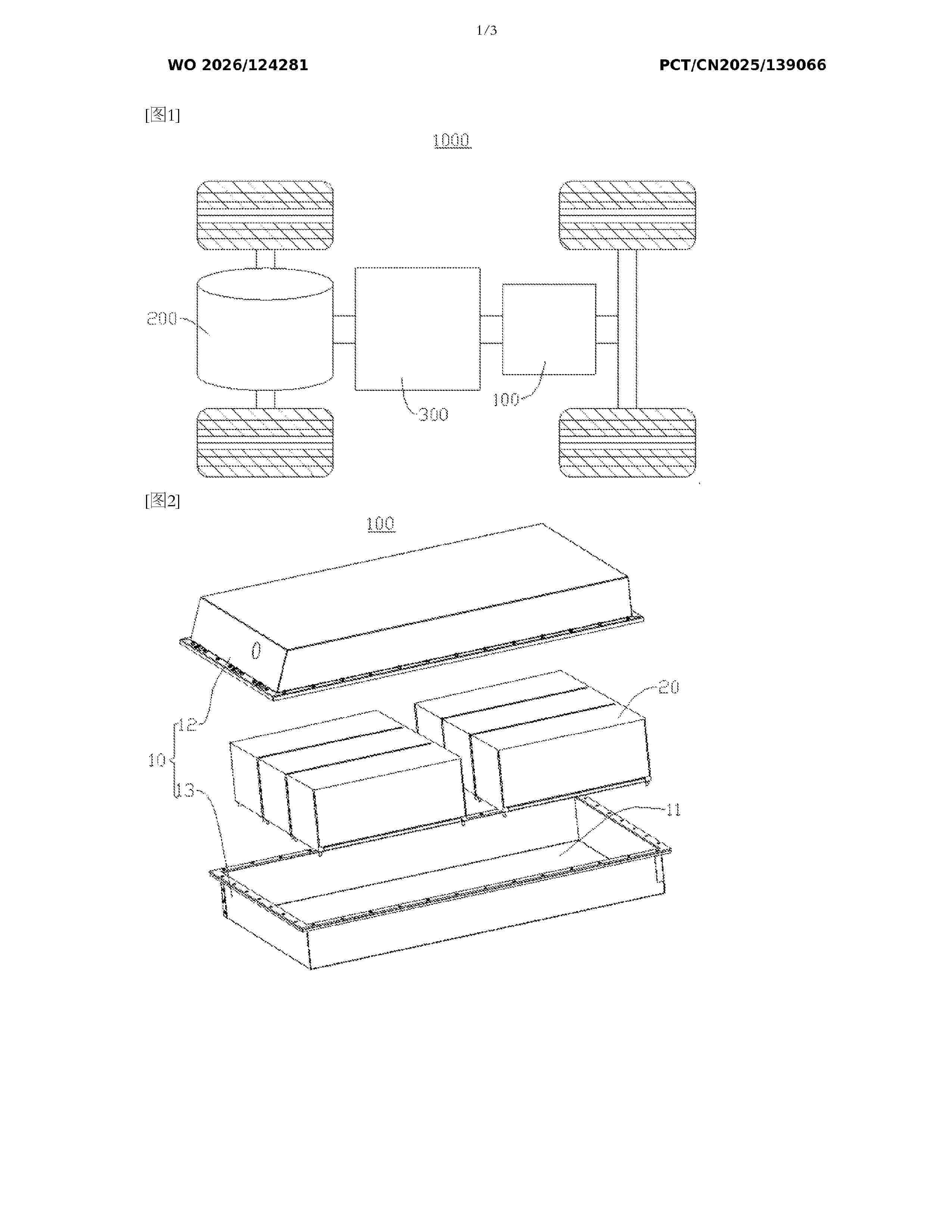
Resumen de: WO2026124281A1
A secondary battery and an electric device, relating to the technical field of secondary batteries. NaaMbNicFedMneO2 is used as a positive electrode active material. A propylene carbonate compound is used as an electrolyte solvent, wherein the activity of H in the propylene carbonate compound is low, such that the propylene carbonate compound has good oxidation resistance, thereby inhibiting the formation of RH+ to a certain extent, and achieving the effect of inhibiting gas generation from reduction at a negative electrode. Moreover, when a nickel-iron-manganese layered metal oxide is used as the positive electrode active material, a cyclic sulfate compound is used as an additive, so that a CEI film can be formed on a positive electrode, thereby inhibiting gas generation from the oxidative decomposition of an electrolyte by a sodium layered oxide, and reducing the formation of RH+. Moreover, since the reduction potential of the cyclic sulfate compound is higher than that of the propylene carbonate compound, the cyclic sulfate compound can form an SEI film before the reduction of the propylene carbonate compound at the negative electrode, thereby inhibiting the formation of the oxidation product RH+ and gas generation from reduction of the electrolyte solvent at the negative electrode.
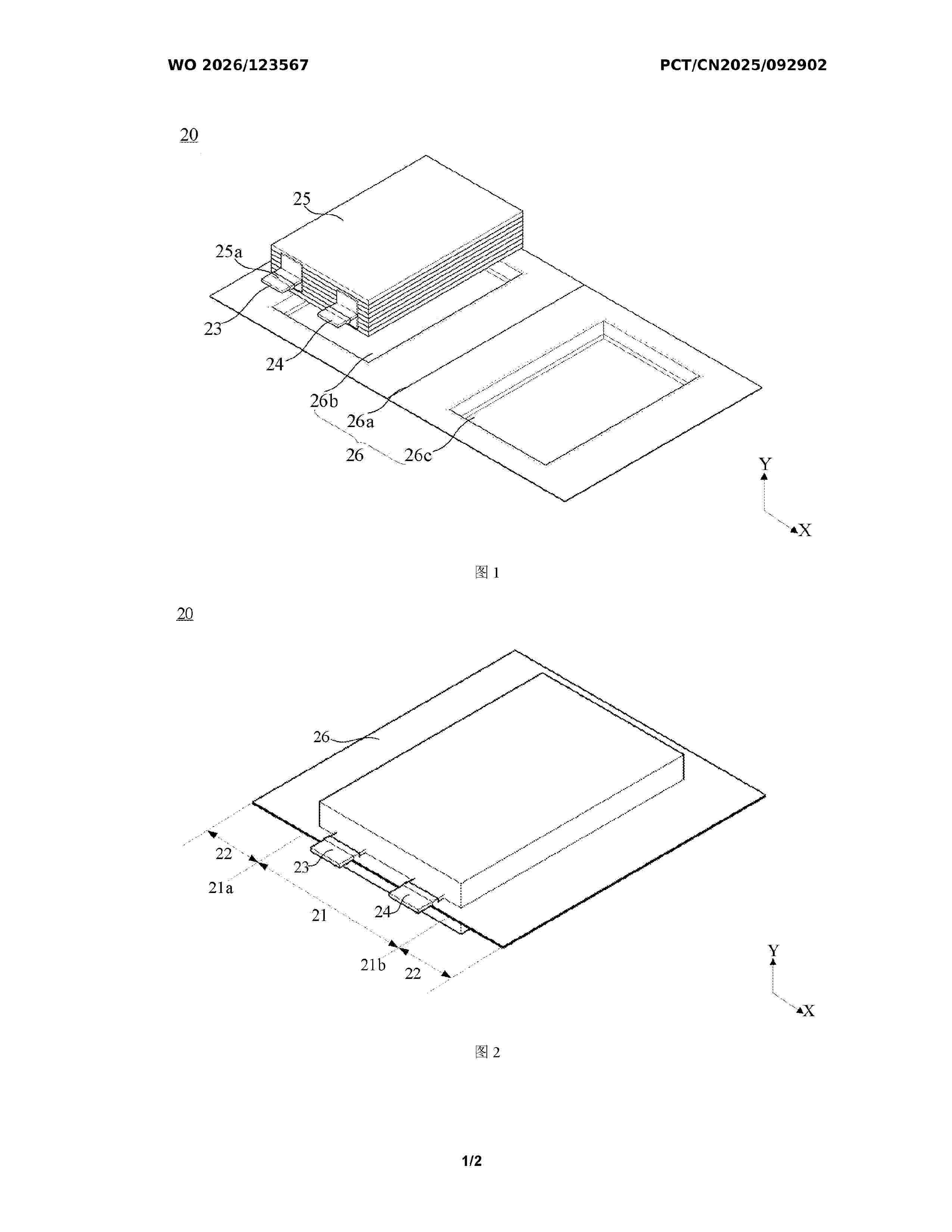
Resumen de: WO2026123567A1
The present application relates to a packaging mechanism, a battery production system, and a battery packaging method. The packaging mechanism comprises a first packaging member (100) and a second packaging member (200), and the first packaging member (100) and the second packaging member (200) are arranged opposite to each other and are used for jointly packaging a battery (20). The first packaging member (100) comprises a primary sealing head (110) and a secondary sealing head (120), and the hardness of the primary sealing head (110) is less than the hardness of the secondary sealing head (120). The battery production system comprises the packaging mechanism. The battery packaging method comprises the following steps: driving the primary sealing head (110) and the second packaging member (200) to package a first sealing region (21); and driving the secondary sealing head (120) and the second packaging member (200) to package a second sealing region (22). In the packaging mechanism, battery production system, and battery packaging method, when the primary sealing head (110) is pressed onto a region where a tab adapter piece is located, the primary sealing head (110) is capable of undergoing relatively large elastic deformation.
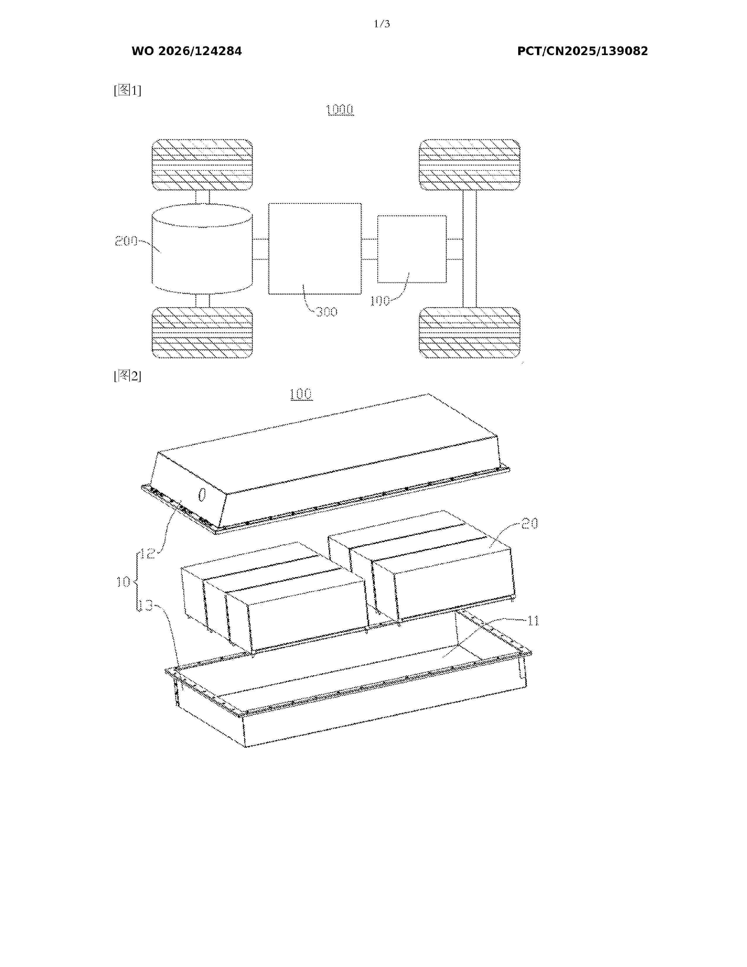
Resumen de: WO2026124284A1
A secondary battery and an electric device, relating to the technical field of secondary batteries. When a positive electrode active material is a nickel-iron-manganese layered metal oxide, a cyclic sulfate ester compound is capable of forming films on both a positive electrode sheet and a negative electrode sheet, and a CEI film formed on the positive electrode sheet suppresses a side reaction between the nickel-iron-manganese layered metal oxide and a non-aqueous electrolyte, thereby improving the cycle performance of the secondary battery and reducing gas generation during high-SOC storage. Moreover, a difluorooxalatoborate salt compound, which has a higher reduction potential than the cyclic sulfate ester compound, is selected, the difluorooxalatoborate salt compound is capable of preferentially forming an inorganic SEI film on the surface of a negative electrode sheet prior to the cyclic sulfate ester compound, and the inorganic SEI film is distributed in a dot-like manner to occupy some of surface active sites of a negative electrode active material, thereby reducing extensive formation of an organic polymer-type SEI film by the cyclic sulfate ester compound on the negative electrode sheet, so that the overall impedance of the SEI film is low, reducing the DCR of the secondary battery, and isolating the electrolyte from a negative electrode to suppress gas generation caused by reduction at the negative electrode.
Nº publicación: WO2026125595A1 18/06/2026
Solicitante:
INFINEUM INTERNATIONAL LTD [GB]
INFINEUM INTERNATIONAL LIMITED
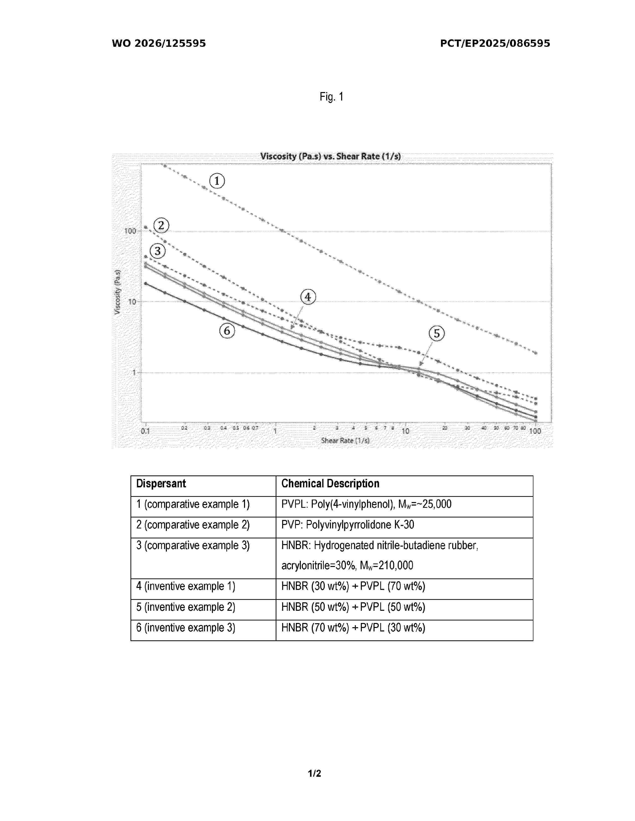
Resumen de: WO2026125595A1
Polymer blends having an organic nitrile-based copolymer, and a phenol-based polymer or a phenol-based copolymer. The organic nitrile-based copolymer has structural units comprising the residue of a substituted or unsubstituted, unsaturated organic nitrile monomer, and structural units comprising the residue of a substituted or unsubstituted, conjugated diene monomer. The phenol-based polymer has structural units comprising the residue of a substituted or unsubstituted, unsaturated phenolic monomer. The phenol-based copolymer has structural units comprising the residue of a substituted or unsubstituted, unsaturated coupled phenolic resin. The organic nitrile-based copolymer is present in an amount from about 0.5 wt% to about 99.5 wt%, and the phenol-based polymer, or the phenol-based copolymer, is present in an amount from about 0.5 wt% to about 99.5 wt%, based on the total weight of the polymer blend. The polymer blends are effective as synergistic dispersants.
 BOPI
BOPI
 Sede Electrónica