Si deseas distinguir tus productos, servicios o ambos de los de otra empresa, es posible que necesites una marca o nombre comercial. Descubre qué son, en qué consiste su procedimiento de registro y qué implica.

Información sobre los plazos de presentación de solicitudes de transformación de marcas de la Unión Europea en marca nacional española. Más información


Si tienes un nuevo dispositivo, producto o procedimiento que resuelva un problema técnico o tenga una ventaja práctica, existen distintas formas de protegerlo en España y en otros países. Descubre cómo hacerlo.

¿Tu innovación reside en la estética, la ornamentación o la apariencia de tu producto? Protégela mediante un diseño industrial. Descubre qué derechos confiere el registro y cómo realizar la tramitación.

Las indicaciones geográficas protegen el nombre de un producto originario de una zona geográfica, a la cual le debe una determinada calidad, reputación u otra característica. Descubre qué son, en qué consiste su procedimiento de registro y qué beneficios conceden.

Las patentes publicadas en todo el mundo son una valiosa fuente de información científica, técnica y comercial.

Si eres emprendedor/a o una empresa y quieres potenciar y mejorar la rentabilidad de tu negocio protegiendo de forma adecuada los activos intangibles de tu organización, en este espacio encontrarás lo necesario.


 1500
resultados
1500
resultados
 Última actualización
27/06/2026 [07:57:00]
Última actualización
27/06/2026 [07:57:00]


 Resultados 500 a 525 de 1500

Resumen de: EP4765304A1
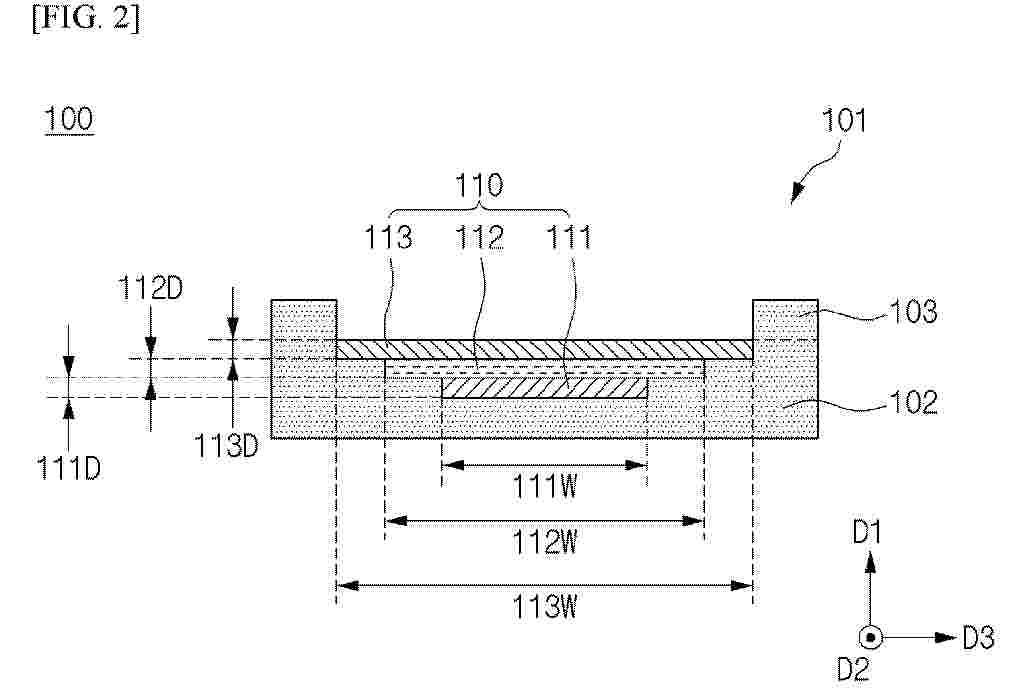
According to exemplary embodiments, a wire-type secondary battery is provided. The wire-type secondary battery includes: a support including a core and a helical guide extending along a surface of the core; a first electrode helically wound along the surface of the core between the guides; a first separator layer provided on an outer side of the first electrode and helically wound along the first electrode; and a second electrode provided on an outer side of the first separator layer and helically wound along the first separator layer. The support includes: a first groove into which the first electrode is inserted; a second groove into which the first separator layer is inserted; and a third groove into which the second electrode is inserted. A width of the second groove is greater than a width of the first groove.

Resumen de: EP4763321A1
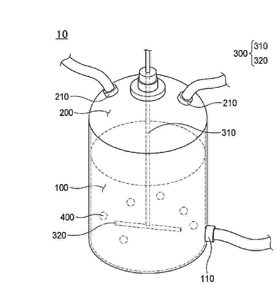
0001 A slurry mixing device includes: a lower housing including an accommodation portion that accommodates slurry and having an open upper side; an upper cover located above the lower housing and having one or more inlets; an agitator having one side located inside the lower housing to mix the slurry; and one or more first mixing members located inside the lower housing.
Resumen de: EP4764934A1
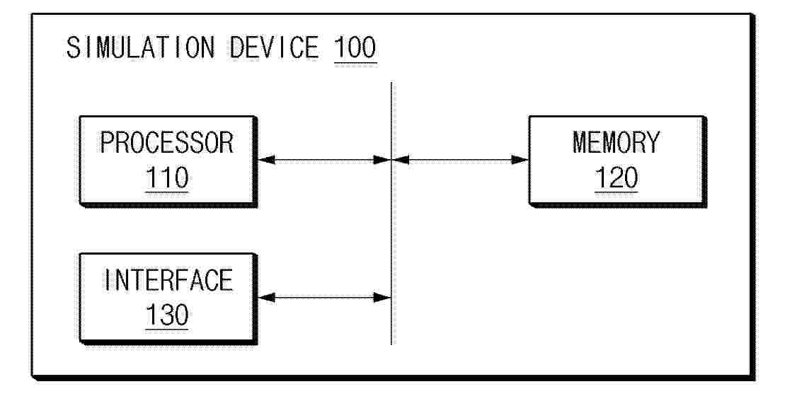
0001 A simulation device according to an embodiment disclosed herein includes an interface configured to acquire data related to a battery cell and at least one processor, and the at least one processor is configured to identify a first length from a first point on a first surface of a first portion including an electrode of the battery cell to a second point where a tab protrudes onto the first surface, identify a height from the first surface to a second portion to be coupled with the first portion, identify a second length from a third point where the tab extending from the second point protrudes onto a second surface of the second portion to a fourth point on the second surface where an end of the tab is to be positioned, and identify an entire length of the tab based on at least one of the first length, the height, the second length, or any combination thereof.
Resumen de: EP4765319A1
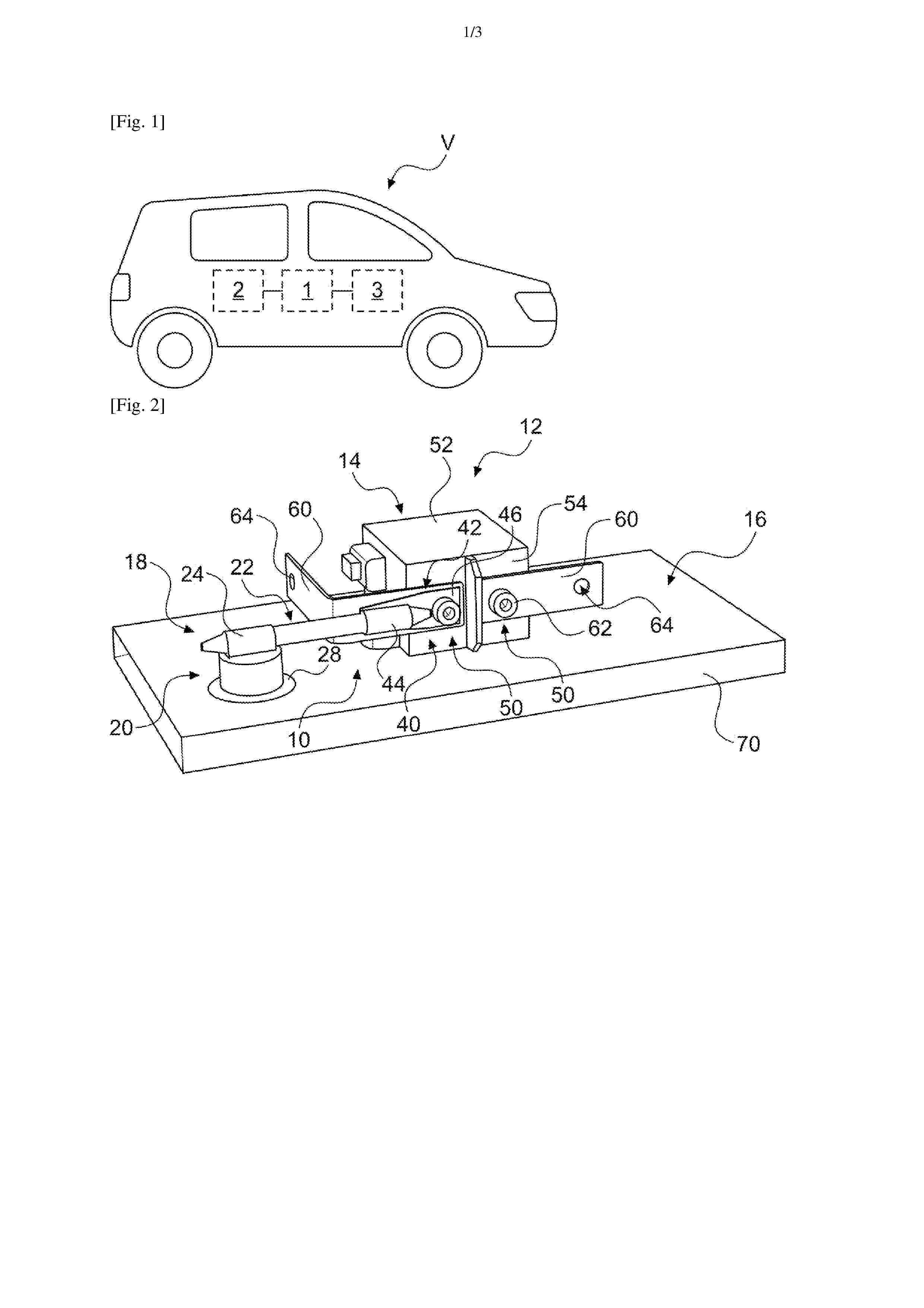
0001 Disclosed are a leakage detection device including a moisture detection unit to which an absorption member is coupled, a fixing support portion configured to fix the moisture detection unit to a battery pack, and an extension portion configured to fix the moisture detection unit to the fixing support portion, wherein a lower end of the absorption member extends at least to a lower end of the fixing support portion, and a battery pack including the same. It is possible to rapidly detect even a small amount of coolant leakage.
Resumen de: EP4765278A1
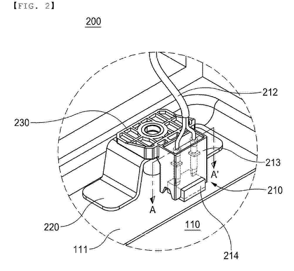
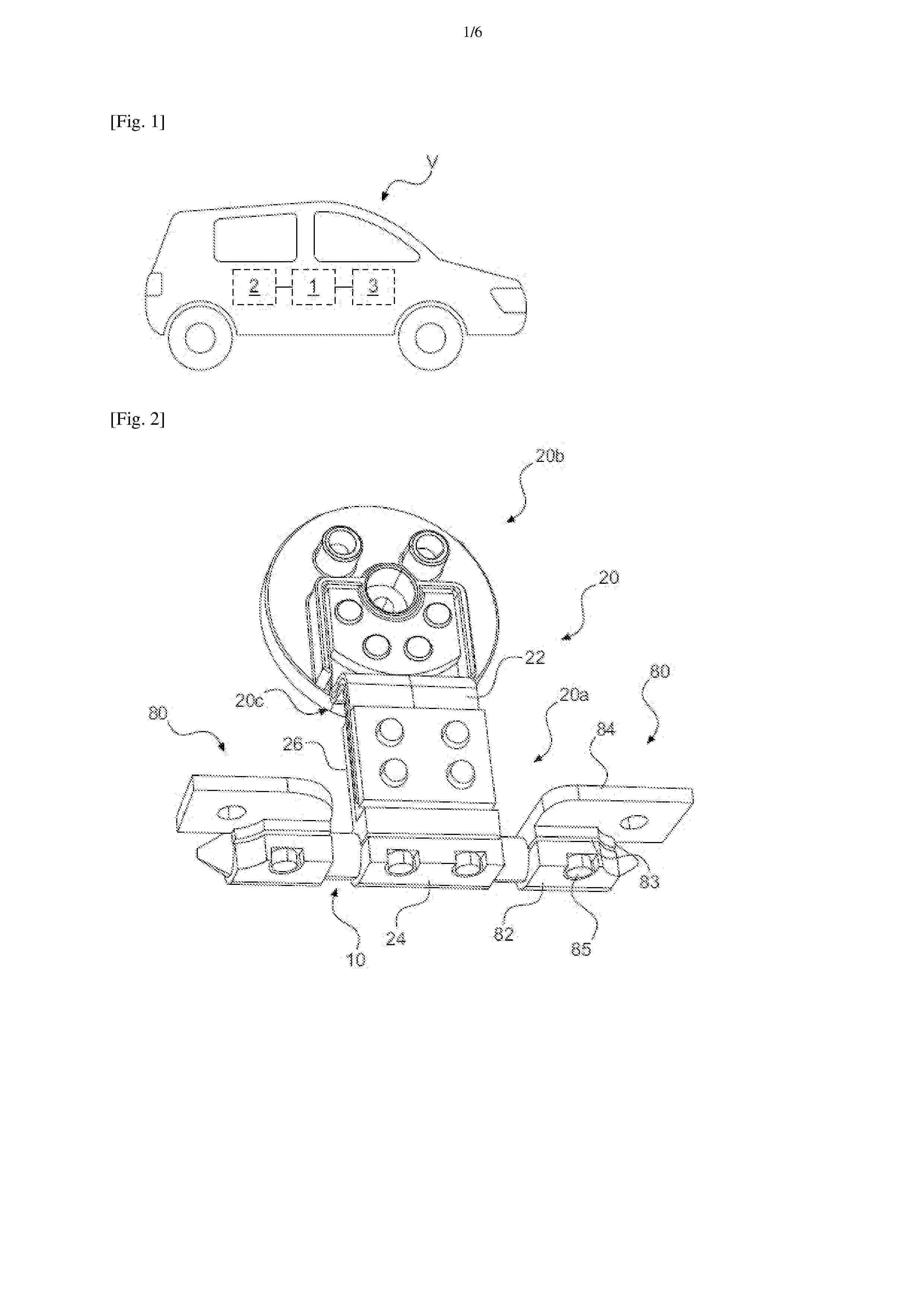
0001 According to an embodiment of the present disclosure, an insulating tape attachment device includes a supply disk, around which an insulating tape is wound such that an adhesive surface faces outward, supplying the insulating tape, a cutting disk rotating, while facing the supply disk, and cutting the insulating tape wound around and supplied from the supply disk at a preset interval, and a main disk carrying the electrode assembly and bringing the cut insulating tape supplied by the supply disk into contact with the electrode assembly to attach the insulating tape to the electrode assembly.
Resumen de: EP4765382A1
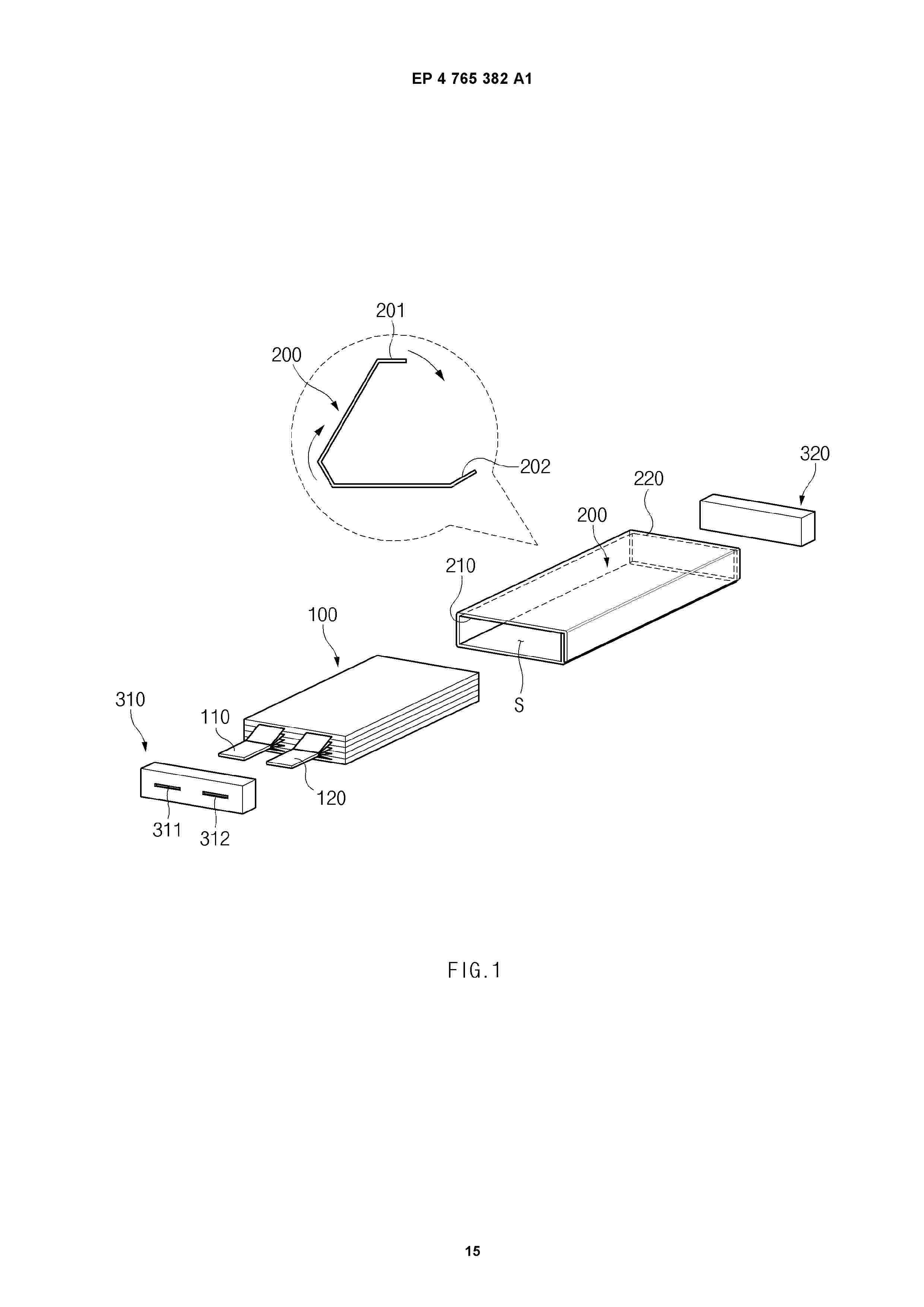
The present disclosure relates to a secondary battery and a method for manufacturing a secondary battery, and more specifically, to a secondary battery that can be repeatedly charged and discharged and a method for manufacturing the same. A secondary battery according to an embodiment of the present disclosure may include an electrode assembly; an exterior material having an internal space accommodating the electrode assembly and first and second exterior material openings allowing the internal space to communicate with the outside; a first cap sealing the first exterior material opening; a second cap sealing the second exterior material opening; and a positive electrode lead and a negative electrode lead connected to the electrode assembly and at least partially exposed to the outside by penetrating the first cap. At this time, the first cap and the second cap may be coupled to the inner surface of the exterior material, and the bonding force between the first cap and the inner surface of the exterior material may be stronger than the bonding force between the second cap and the inner surface of the exterior material.
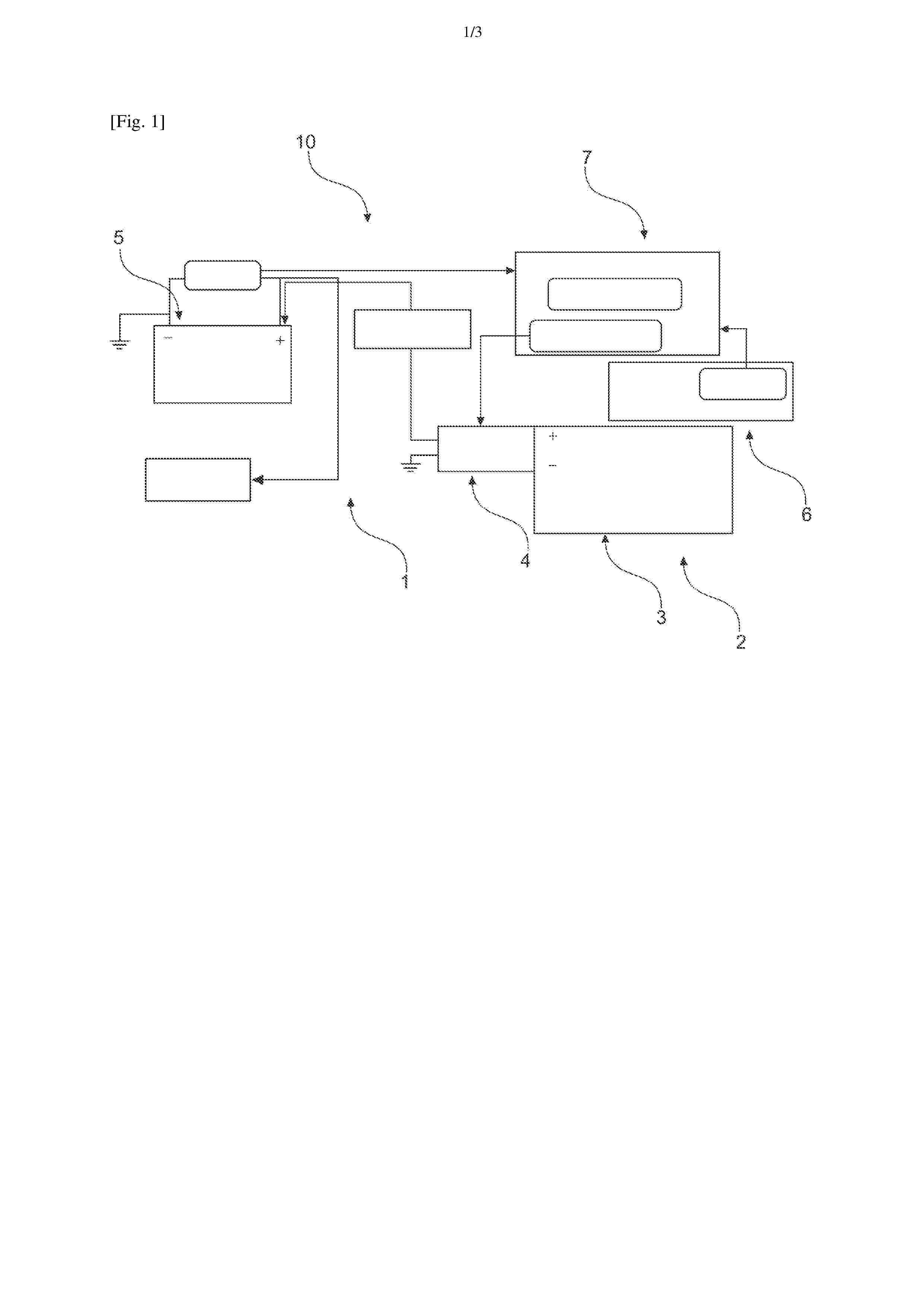
Resumen de: EP4764533A1
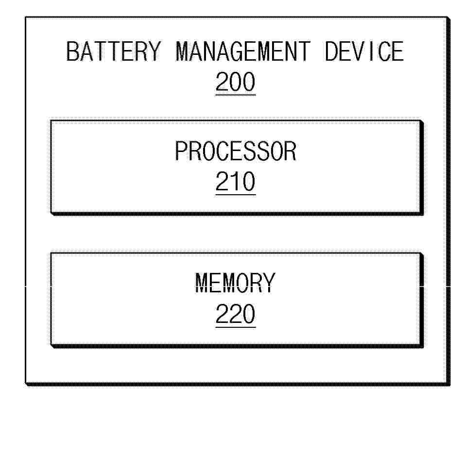
A battery management device according to an embodiment of this document includes a memory configured to store one or more instructions and a processor configured to execute the one or more instructions, and the processor is configured to acquire a reference voltage for determining initial driving batteries among a plurality of batteries based on factors acquired from a plurality of cells included in each of the plurality of batteries, and manage a connection state of each of the plurality of batteries based on the reference voltage.
Resumen de: FR3170123A3
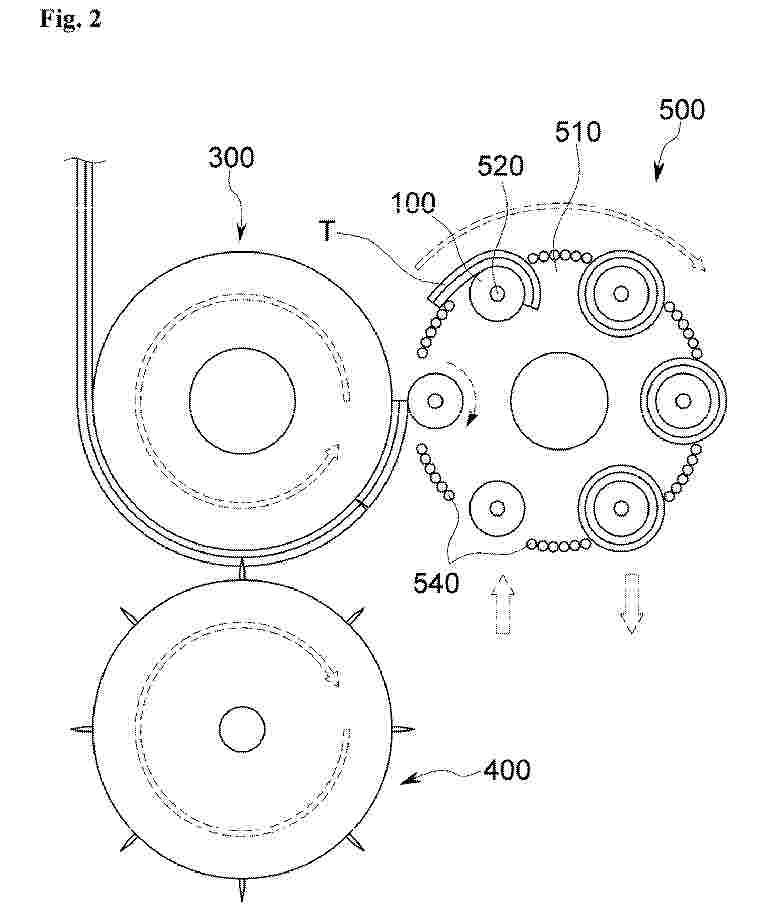
Une batterie prismatique (20) comprend : une pile (22) de cellules de batterie prismatique (24) empilés le long d'un axe de référence (100), un boîtier (26) qui abrite la pile (22), au moins une plaque d'extrémité (28) située à l'intérieur du boîtier (26) à une extrémité axiale de la pile (22) et au moins une unité de sollicitation comprenant au moins un élément de sollicitation mobile (34) en contact avec une face de contact de la plaque d'extrémité (28) à l'opposé de la pile (22), et au moins un ressort (38) appliquant une force de sollicitation à l'élément de sollicitation en direction de la pile (22), de sorte que l'élément de sollicitation (34) applique une force de pression à la plaque d'extrémité (28) avec une composante de force de pression axiale (36) en direction de la pile (22). L'unité de sollicitation (32) est fixée de manière amovible au boîtier (26) et dotée d'un cadre (40) qui abrite le ressort (38) et guide l'élément de sollicitation (34). (Figure 4)
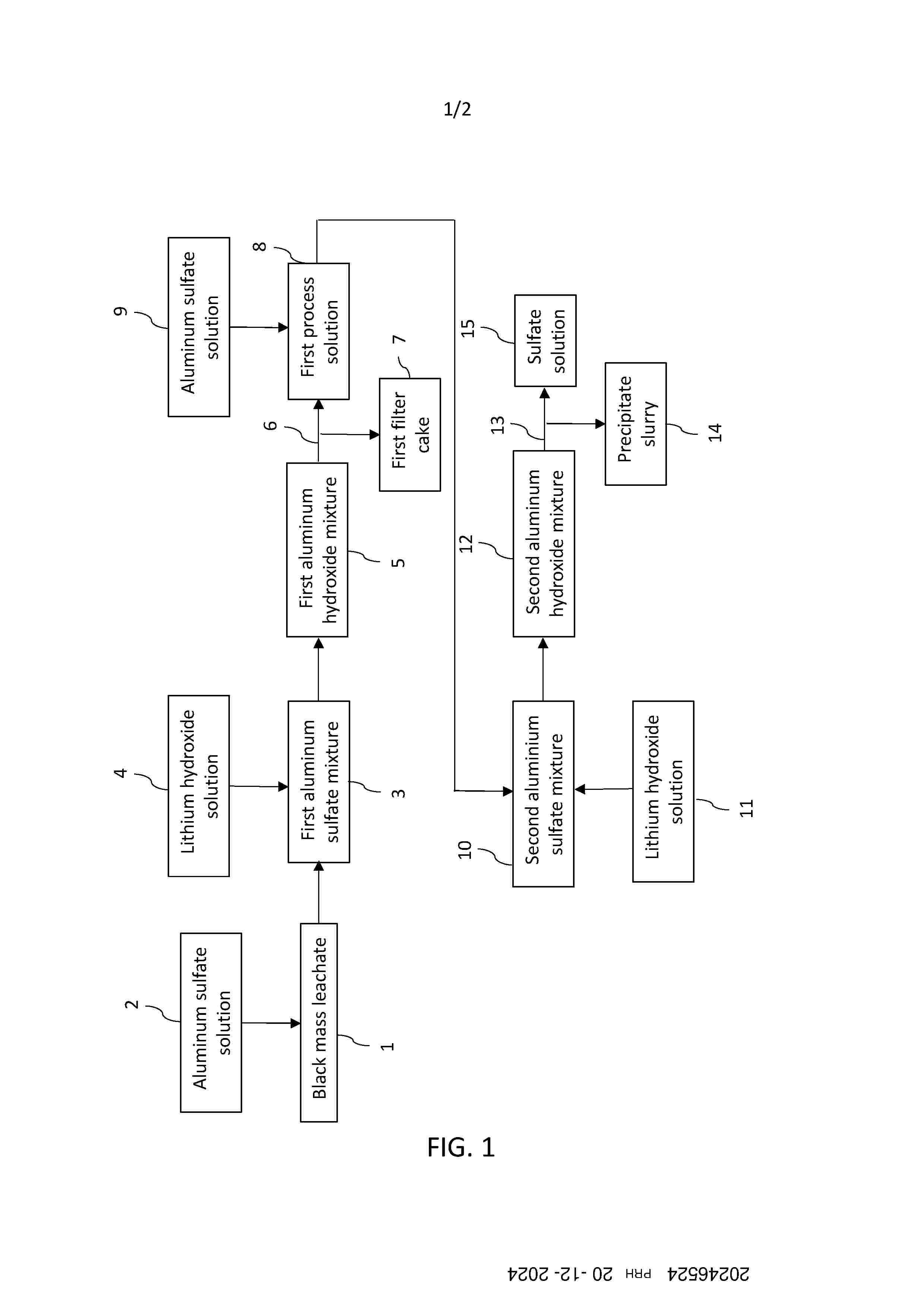
Resumen de: FI20246524A1
According to an example aspect, there is provided a method for precipitating impurities from a black mass leachate, comprising steps of: 1a) providing a black mass leachate (1) comprising at least one of nickel, cobalt and lithium, and impurities; 1b) mixing an aluminum sulfate solution (2) with the black mass leachate (1) to produce a first aluminum sulfate mixture (3); 1c) adding a lithium hydroxide solution (4) to the first aluminum sulfate mixture (3), to produce a first aluminum hydroxide mixture (5); 1d) filtrating (6) the first aluminum hydroxide mixture (5), to produce a first filter cake (7) comprising impurities and a first process solution (8); 2a) mixing an aluminum sulfate solution (9) with the first process solution (8), to produce a second aluminum sulfate mixture (10); 2b) adding a lithium hydroxide solution (11) to the second aluminum sulfate mixture (10), to produce a second aluminum hydroxide mixture (12); 2c) filtrating (13) the second aluminum hydroxide mixture (12), to produce a precipitate slurry comprising residual impurities and a sulfate solution (15).
Resumen de: FR3170114A1
La présente invention concerne un procédé de préparation d’un matériau précurseur d’un matériau actif de cathode enrobé comprenant : (a) une étape de préparation d’une solution contenant un hydroxyde, un nitrate, un acétate ou un alcoxyde d’un métal M avec M différent du lithium, (b) une étape de mise en contact des particules d’un matériau précurseur d’un matériau actif de cathode sous forme d’oxyde, d’hydroxyde ou de carbonate avec la solution préparée à l’étape a), (c) éventuellement une étape de récupération des particules obtenues à l’issue de l’étape b), (d) une étape de séchage de la suspension obtenue à l’issue de l’étape b) ou éventuellement des particules récupérées lors de l’étape c) moyennant quoi un matériau précurseur d’un matériau actif de cathode enrobé par une couche à base de métal M est obtenu. La présente invention concerne également le matériau précurseur d’un matériau actif de cathode enrobé ainsi préparé, son utilisation pour préparer un matériau actif de cathode enrobé et ce matériau actif de cathode.
Resumen de: FR3170104A1
L’agencement (1) de ventilation pour boîtier de batterie inclut un corps (2) de montage, recouvrant par le dessus une ouverture du boîtier et un pourtour d’ouverture défini par une paroi (P) du boîtier, un canal étant prévu dans le corps en s’étendant jusqu’à un capot (3). Le canal guide un échappement gazeux (FG) provenant de l’intérieur du boîtier et le capot peut s’éjecter en cas de forte surpression. Une grille ou composant protecteur (4), typiquement métallique et ainsi thermiquement résistante, assure une protection anti-feu en se plaçant sous le corps (2) à l’opposé du capot. Le composant (4) inclut des attaches (5) s’engageant à l’intérieur du boîtier et obture le canal par le dessous tout en étant fixé indépendamment à la paroi (P) du boîtier, afin de conserver la protection même en cas de fonte du corps qui se raccorde à la paroi (P) en périphérie du composant. Figure de l’abrégé : Figure 2
Resumen de: FR3170120A1
Un aspect de l’invention concerne un pack batterie 1 de véhicule automobile comportant un réceptacle 2 et un couvercle 3 coopérant avec ledit réceptacle 2 pour former un espace interne 4 de réception de cellules 5, le couvercle 3 comportant une surface inférieure 6 délimitant en partie ledit espace interne 4, la surface inférieure 6 du couvercle 3 est munie d’au moins un moyen de guidage 7 de particules conductrices contenues dans des gaz issus d’au moins une desdites cellules 5, le au moins un moyen de guidage 7 étant agencé pour guider les particules conductrices vers une zone de stockage 8 disposée dans ledit espace interne 4, ladite zone de stockage 8 étant électriquement isolée. Figure 1
Resumen de: FR3170015A1
L’invention concerne un procédé de contrôle d’un accumulateur basse tension, notamment une batterie 12V, ledit accumulateur étant embarqué sur un véhicule automobile, ledit procédé comprenant une étape (20) de surveillance dudit accumulateur et une étape (30) de charge dudit accumulateur en fonction d’un résultat de ladite étape (20) de surveillance, ladite étape (20) de surveillance et/ou ladite étape (30) de charge étant exécutées alors que ledit véhicule est à l’arrêt (mode parking), ladite étape (20) de surveillance comprenant une étape (22) d’évaluation d’un seuil, variable en fonction d’un ou plusieurs paramètres de fonctionnement dudit accumulateur, et une étape (24) de déclenchement de l’étape (30) de charge, ladite étape (24) de déclenchement tenant compte dudit seuil variable. Figure pour l’abrégé : Figure 2
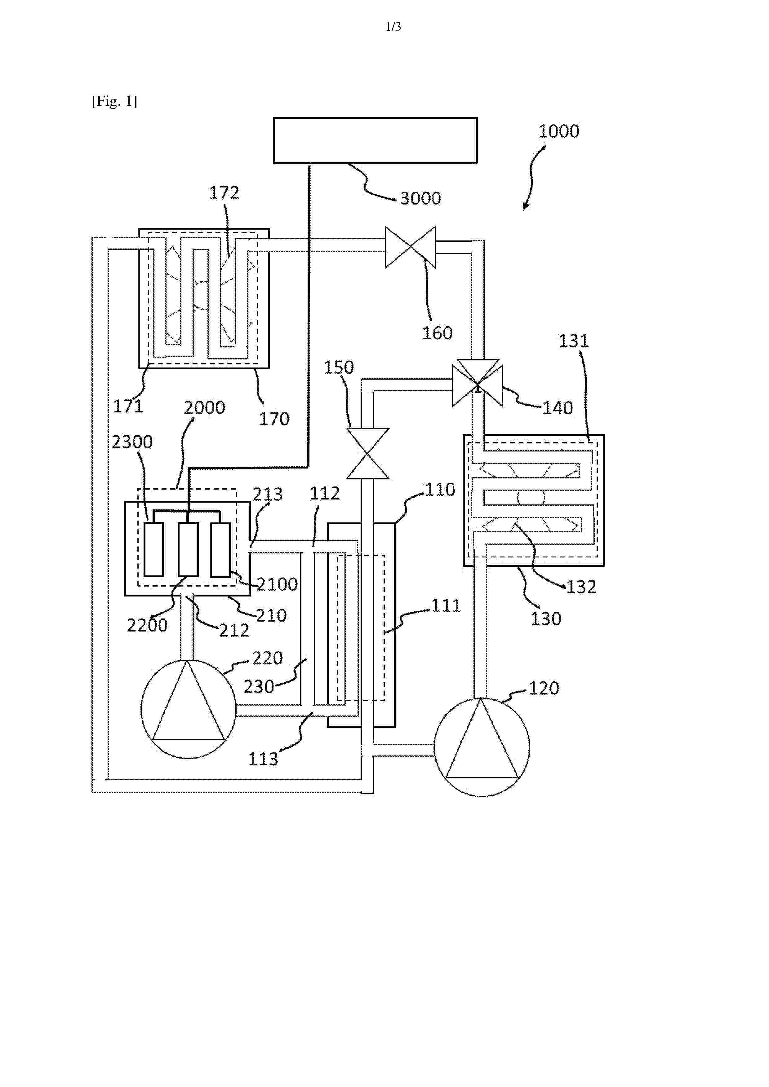
Resumen de: FR3170106A1
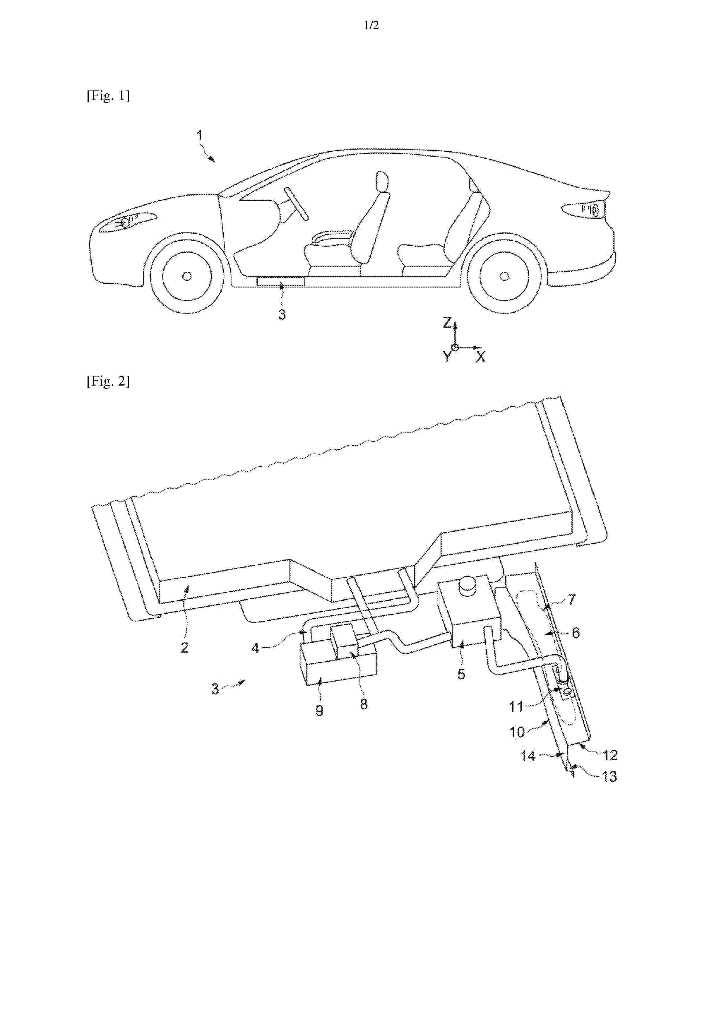
Procédé de refroidissement d’une batterie (2000) d’un moteur (3000) d’un véhicule automobile comprenant un circuit frigorifique (100) incluant un premier évaporateur (110), un circuit d’huile diélectrique (200) comprenant un réservoir (210) contenant une huile diélectrique et des cellules (2100, 2200, 2300) de la batterie (2000) baignant dans l’huile diélectrique, le procédé étant caractérisé en ce qu’il comprend : Une circulation d’un fluide frigorigène par le circuit frigorifique (100) comprenant une évaporation du fluide frigorigène dans le premier évaporateur (110),Une circulation de l’huile diélectrique par le circuit d’huile diélectrique (200), comprenant :Une circulation de l’huile diélectrique dans le réservoir (210),Une circulation de l’huile diélectrique dans le premier évaporateur (110), comprenant un premier échange de chaleur, mis en œuvre par un échangeur de chaleur (111) du premier évaporateur (110), au cours de l’évaporation du fluide frigorigène, en prenant de l’énergie à l’huile diélectrique. Figure pour l’abrégé : figure 2
Resumen de: FR3170110A1
Dispositif de dissipation thermique, notamment pour véhicule automobile, ledit dispositif comprenant un caloduc (10) configuré pour un échange thermique entre, d’une part, une source chaude (12) comprenant un organe électrique (14), et, d’autre part, une source froide, ledit dispositif comprenant en outre un premier organe d’interface thermique (20), dit chaud, et des conducteurs électriques (22) destinés à être connectés électriquement à des bornes de connexion électrique dudit organe électrique (14), lesdites bornes présentant des potentiels électriques différents, ledit organe d’interface thermique chaud (20) étant configuré pour un transfert de chaleur entre ledit caloduc (10) et lesdits conducteurs électriques (22) ainsi que pour établir un pont thermique entre lesdits conducteurs électriques (22) tout en les isolant électriquement les uns des autres, ledit organe d’interface thermique chaud (20) comprenant une bride de fixation (30) destinée à être fixée auxdits conducteurs électriques (22). Figure pour l’abrégé : Figure 3
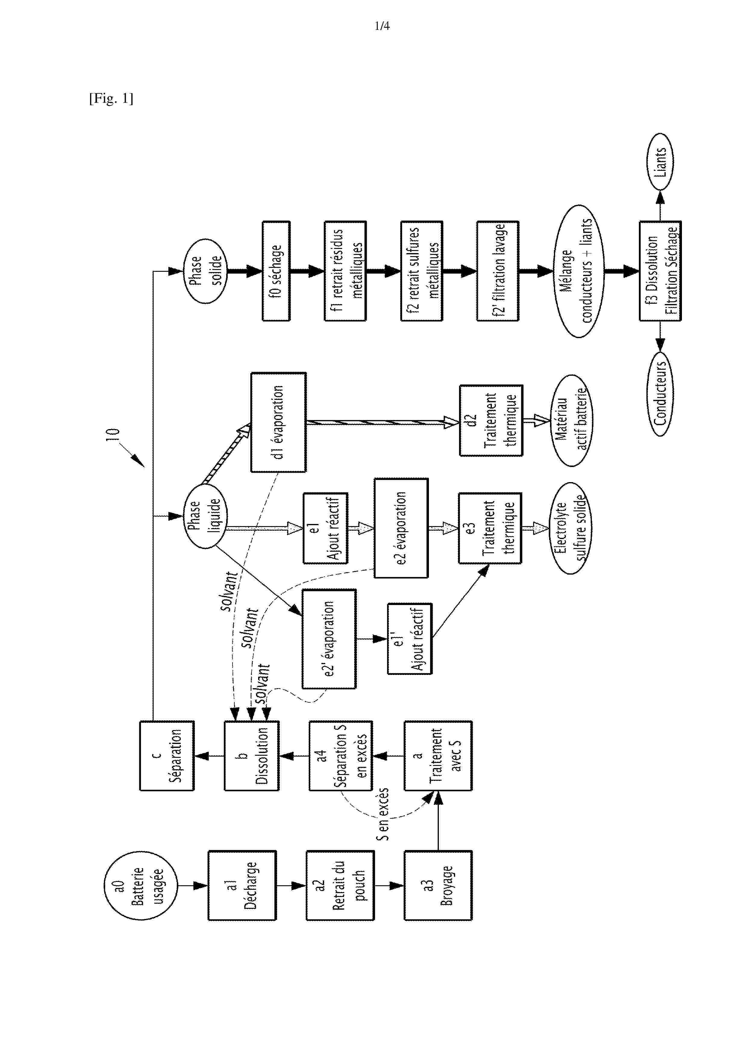
Resumen de: FR3170103A1
Procédé de recyclage d’éléments électrochimiques à électrode négative comprenant un métal alcalin La présente invention concerne un procédé de recyclage d’un élément électrochimique comprenant une électrode négative présentant une couche active négative comprenant un métal alcalin M sous forme métallique et/ou sous forme d’un alliage, M étant choisi parmi Li, Na et K, le procédé comprenant une étape a) de mise en contact du métal alcalin M avec du soufre élémentaire pour produire du M2S, l’étape a) de mise en contact étant mise en œuvre en l’absence de solvant. Figure pour l'abrégé : Figure 1
Resumen de: FR3169781A1
Dispositif de dissipation thermique, notamment pour véhicule automobile, ledit dispositif étant configuré pour un échange thermique entre, d’une part, une source chaude (12) comprenant un organe électrique (14), et, d’autre part, une source froide (16), ledit dispositif comprenant un premier organe d’interface thermique (18), destiné à être à un potentiel électrique sensiblement identique à un potentiel électrique dudit organe électrique (14), ledit premier organe d’interface thermique (18) étant configuré pour une conduction de chaleur provenant de la source chaude (12) en direction de la source froide (16), ledit dispositif comprenant en outre un premier boîtier (20) accueillant un fluide diélectrique, ledit premier boîtier étant configuré pour établir un échange thermique entre ledit premier organe d’interface thermique (18) et ladite source froide (16). Figure pour l’abrégé : Figure 2
Resumen de: FR3169782A1
Dispositif de dissipation thermique, notamment pour véhicule automobile, ledit dispositif étant configuré pour un échange thermique entre, d’une part, une source chaude comprenant un organe électrique, et, d’autre part, une source froide, ledit dispositif comprenant en outre un premier organe d’interface thermique (20), ledit premier organe d’interface thermique comprenant une tête (20b) destinée à être en relation d’échange thermique avec l’une desdites sources chaude ou froide, ladite tête (20b) comprenant un matériau thermiquement conducteur et électriquement isolant (40) destiné à être en contact avec ladite source chaude ou froide en cause, ladite tête (20b) comprenant en outre une entretoise (44) de protection dudit matériau thermiquement conducteur et électriquement isolant (40). Figure pour l’abrégé : Figure 10
Resumen de: FR3170105A1
Système de refroidissement (3) d’une batterie (2) haute tension pour véhicule automobile (1), comprenant un premier réservoir (5) de liquide diélectrique (6), un deuxième réservoir (7) de liquide diélectrique (6), une pompe de circulation (8) du liquide diélectrique (6) et un échangeur de chaleur (9) apte à réguler la température dudit système de refroidissement (3). Le deuxième réservoir (7) est positionné dans un corps creux (10) du véhicule automobile (1) par des moyens de fixation (11) et est apte à adopter une position rétractée (PR) dans laquelle ledit deuxième réservoir (7) ne comprend pas de liquide diélectrique (6) et une position déployée (PD) dans laquelle ledit deuxième réservoir (7) comprend du liquide diélectrique (6). Figure pour l’abrégé : Fig 2
Resumen de: FR3169783A1
Dispositif de dissipation thermique (300, 300’), notamment pour véhicule automobile, ledit dispositif comprenant des caloducs (10) configurés pour un échange thermique entre, d’une part, des sources chaudes (12) comprenant respectivement un organe électrique (14), et, d’autre part, une source froide (16), ledit dispositif comprenant en outre un premier organe d’interface thermique (20), dit froid, en relation d’échange thermique avec lesdits caloducs (10) et destinée à être en relation d’échange thermique avec ladite source froide (16), de sorte à relier thermiquement chacune desdites sources chaudes (12) avec ladite source froide (16) et à relier électriquement entre elles lesdites sources chaudes (12) par l’intermédiaire desdits caloducs (10) et dudit organe d’interface thermique froid (20). Figure pour l’abrégé : Figure 3
Resumen de: FR3169787A1
Dispositif de dissipation thermique, notamment pour véhicule automobile, ledit dispositif comprenant un caloduc (10) configuré pour un échange thermique entre, d’une part, une source chaude (12) comprenant un organe électrique (14), et, d’autre part, une source froide (16), ledit dispositif comprenant en outre : - un premier organe d’interface thermique (50) en contact avec le caloduc (10) et destinée à être en relation d’échange thermique avec l’une desdites sources chaude ou froide (12, 16), - un deuxième organe d’interface thermique (20) en contact avec le caloduc (10) et destinés à être en relation d’échange thermique avec l’autre desdits sources chaude ou froide (12,16), ledit premier organe d’interface thermique (50) étant configuré pour être mobile en pivotement de sorte à permettre une orientation angulaire dudit caloduc (10). Figure pour l’abrégé : Figure 2
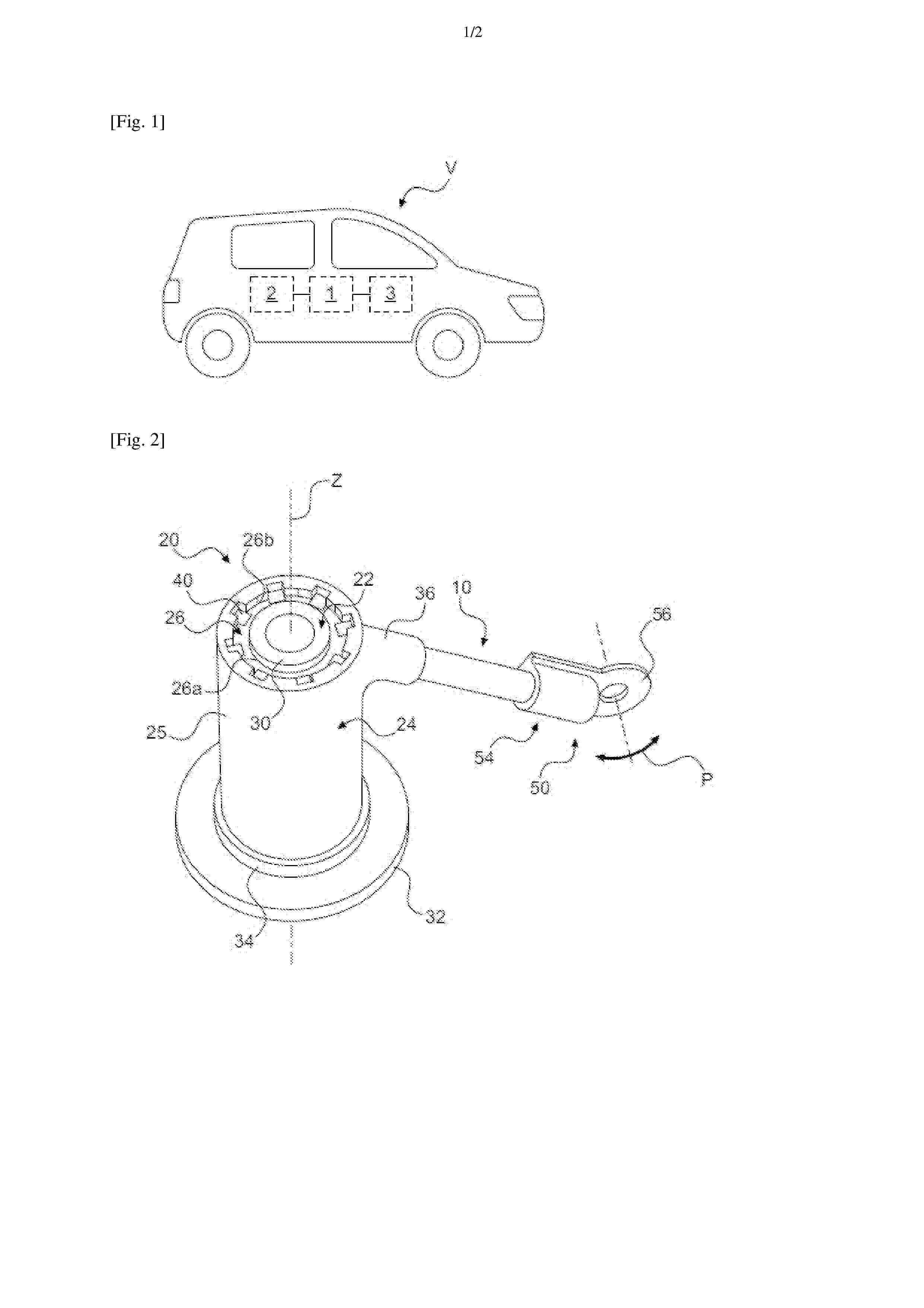
Resumen de: FR3169785A1
Dispositif de dissipation thermique, notamment pour véhicule automobile, ledit dispositif comprenant un ou plusieurs caloducs (10) configurés pour un échange thermique entre, d’une part, une ou plusieurs sources chaudes comprenant respectivement un organe électrique, et, d’autre part, une source froide , ledit dispositif comprenant en outre un premier organe d’interface thermique (20) en relation d’échange thermique avec le ou lesdits caloducs (10) et destinée à être en relation d’échange thermique avec l’une desdites sources chaude ou froide, ledit premier organe d’interface thermique (20) comprenant un pilier (22) de support, destiné à être en contact avec ladite source chaude ou froide, un carter (24), destiné à être en contact avec le ou lesdits caloducs (10), et un insert (26) électriquement isolant et formant un pont thermique entre ledit pilier (22) et ledit carter (24), ledit insert présentant une surface interne (26a) et une surface externe (26b) respectivement en contact avec une surface externe du pilier (22) et une surface interne du carter (24). Figure pour l’abrégé : Figure 2
Resumen de: FR3170108A1
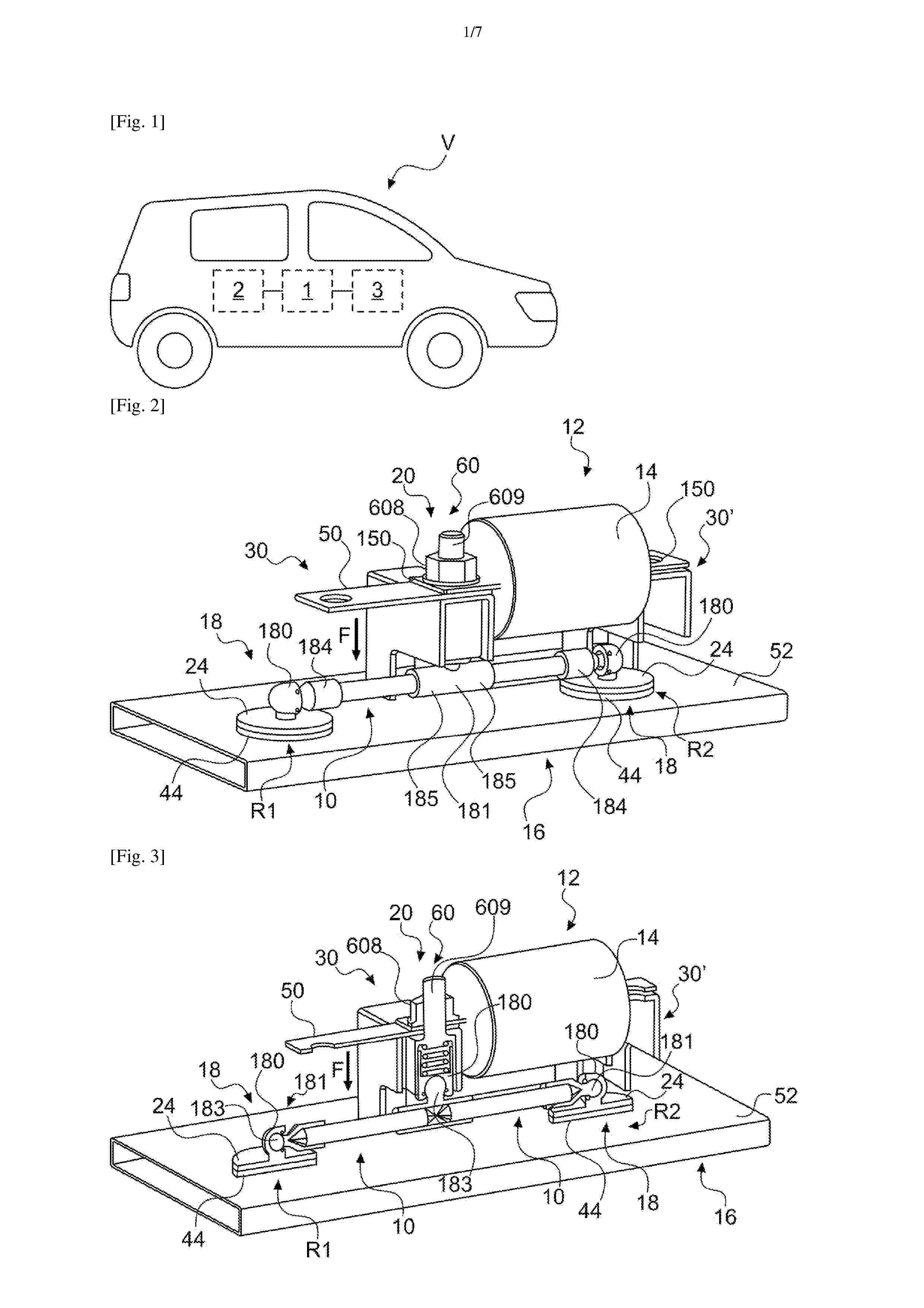
Dispositif de dissipation thermique, notamment pour véhicule automobile, ledit dispositif étant configuré pour une conduction de chaleur entre d’une part, une source chaude (12) comprenant un organe électrique (14), et, d’autre part, une source froide (16), ledit dispositif comprenant une organe d’interface thermique (20), dit chaud, configuré pour être en relation d’échange thermique avec ladite source chaude (12), et une pluralité d’organes d’interface thermique (18), dit froids, configurés pour être en relation d’échange thermique avec ladite source froide (16) selon une distribution spatiale répartie en plusieurs zones distinctes (R1, R2, …), ledit dispositif étant en outre configuré pour un échange thermique entre ledit organe d’interface thermique chaud (12) et lesdits organes d’interface thermique froids (18). Figure pour l’abrégé : Figure 2
Resumen de: FR3170115A1
La présente invention concerne une composition d’électrode comprenant au moins un liant et au moins une matière active pour la préparation d’une électrode de batterie sodium-ion.
Nº publicación: FR3169984A1 19/06/2026
Solicitante:
AMPERE SAS [FR]
AMPERE SAS
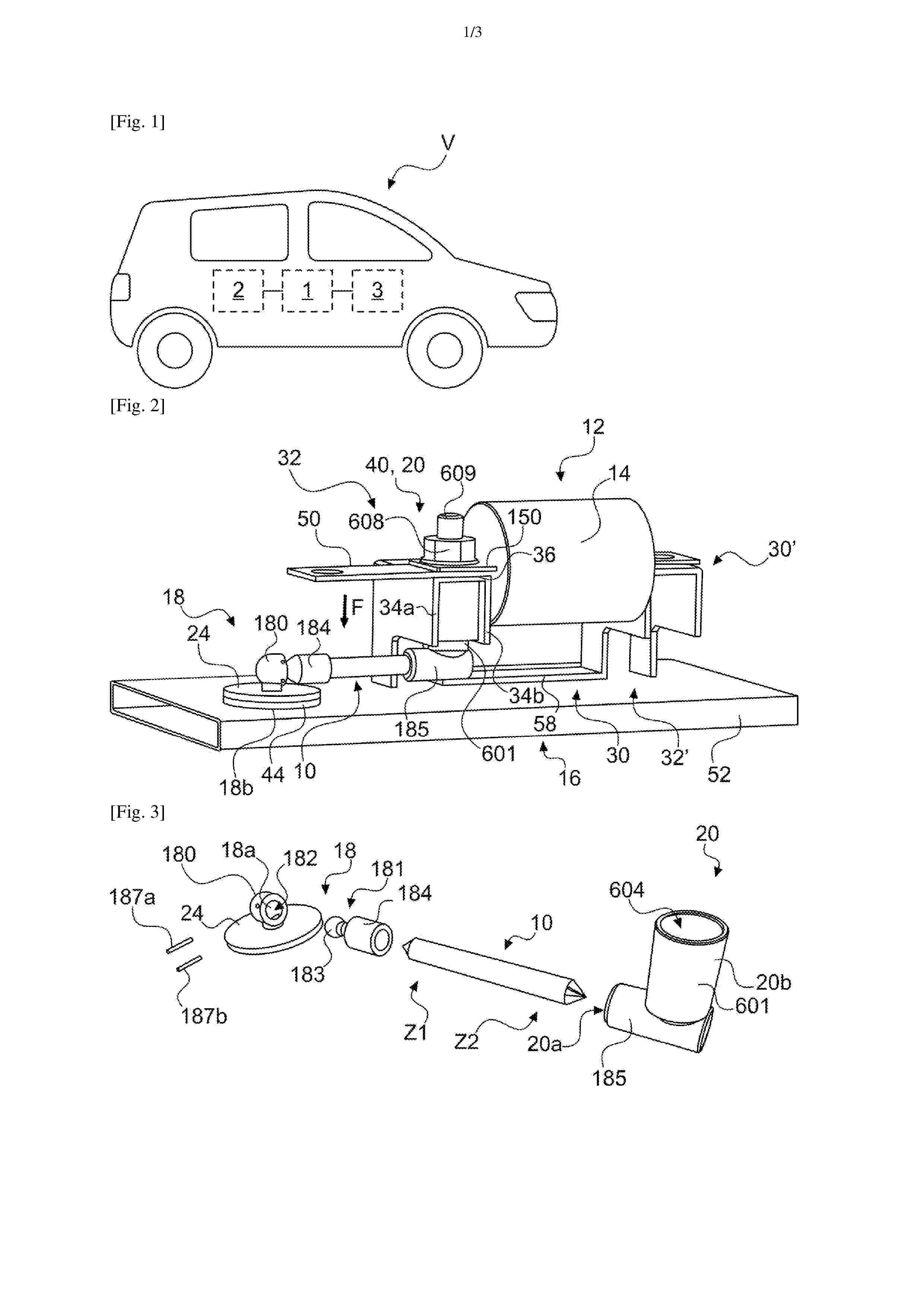
Resumen de: FR3169984A1
Dispositif de dissipation thermique, notamment pour véhicule automobile, ledit dispositif comprenant un caloduc (10) configuré pour un échange thermique entre, d’une part, une source chaude (12) comprenant un organe électrique (14), et, d’autre part, une source froide (16), ledit dispositif comprenant en outre un ou plusieurs organes d’interface thermique (18, 20) configurés pour un échange thermique entre ledit caloduc (10) et l’une desdites sources chaude ou froide (12, 16) le ou lesdits organes d’interface thermique (18, 20) étant configurés pour autoriser une orientation angulaire dudit caloduc(10). Figure pour l’abrégé : Figure 7
 BOPI
BOPI
 Sede Electrónica