Si deseas distinguir tus productos, servicios o ambos de los de otra empresa, es posible que necesites una marca o nombre comercial. Descubre qué son, en qué consiste su procedimiento de registro y qué implica.

Información sobre los plazos de presentación de solicitudes de transformación de marcas de la Unión Europea en marca nacional española. Más información


Si tienes un nuevo dispositivo, producto o procedimiento que resuelva un problema técnico o tenga una ventaja práctica, existen distintas formas de protegerlo en España y en otros países. Descubre cómo hacerlo.

¿Tu innovación reside en la estética, la ornamentación o la apariencia de tu producto? Protégela mediante un diseño industrial. Descubre qué derechos confiere el registro y cómo realizar la tramitación.

Las indicaciones geográficas protegen el nombre de un producto originario de una zona geográfica, a la cual le debe una determinada calidad, reputación u otra característica. Descubre qué son, en qué consiste su procedimiento de registro y qué beneficios conceden.

Las patentes publicadas en todo el mundo son una valiosa fuente de información científica, técnica y comercial.

Si eres emprendedor/a o una empresa y quieres potenciar y mejorar la rentabilidad de tu negocio protegiendo de forma adecuada los activos intangibles de tu organización, en este espacio encontrarás lo necesario.


 1500
resultados
1500
resultados
 Última actualización
27/06/2026 [07:57:00]
Última actualización
27/06/2026 [07:57:00]


 Resultados 525 a 550 de 1500

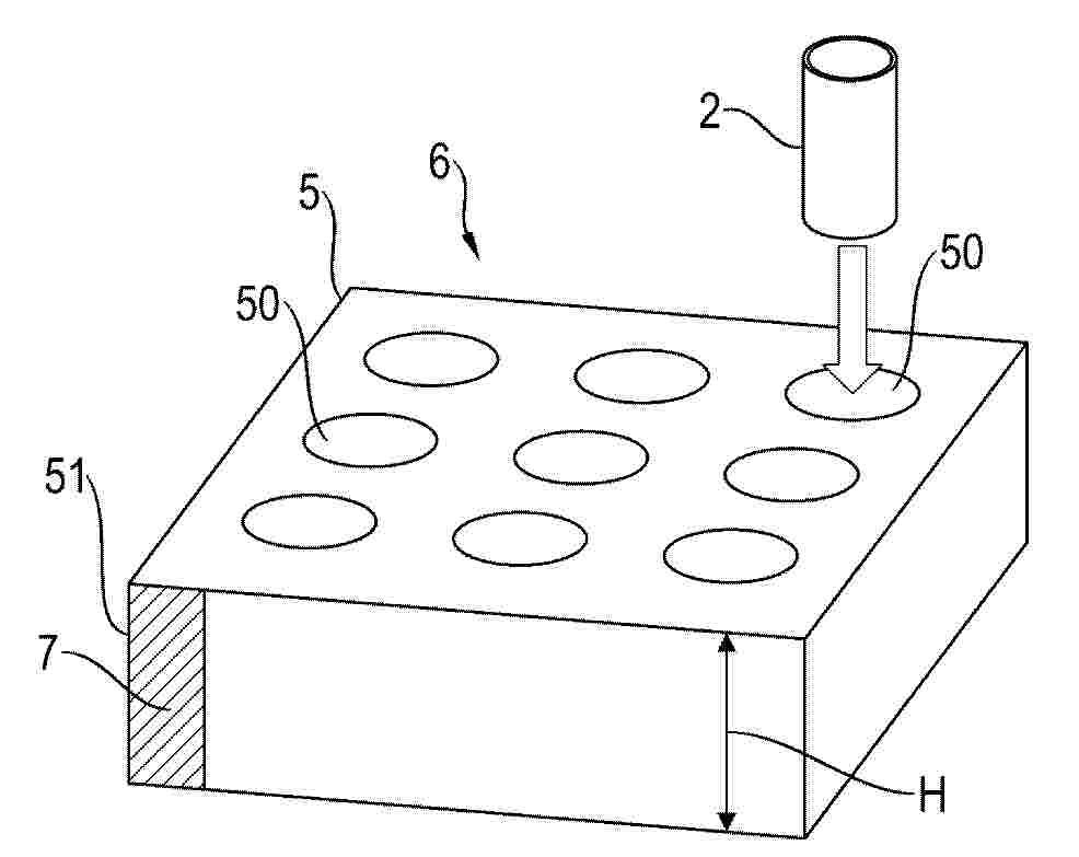
Resumen de: FR3170124A1
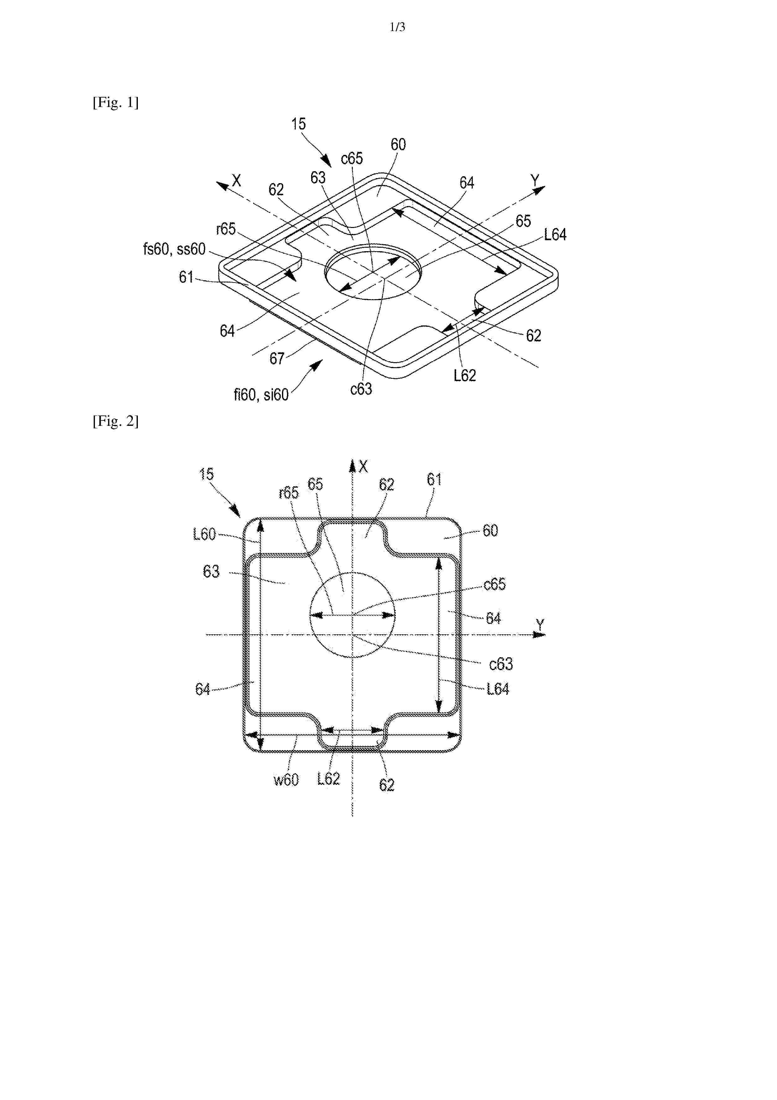
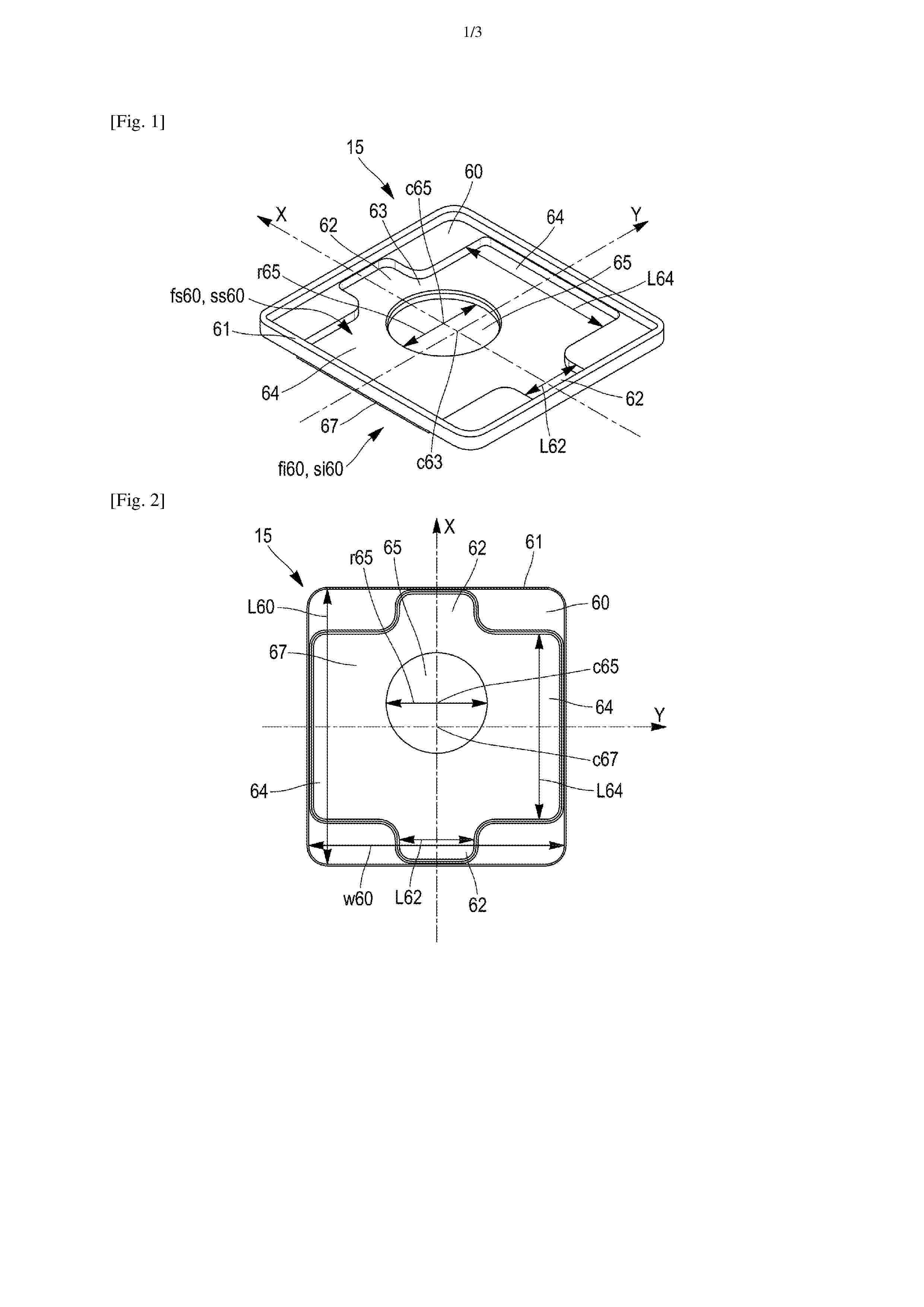
L’invention concerne un organe d’espacement (15) destiné à être interposé entre un couvercle (6) et un terminal (2, 3) d’une cellule de batterie (1) prismatique, ledit organe d’espacement (15) comprenant un corps principal (60) et présentant une face inférieure (fi60) destinée à venir en contact avec le couvercle (6), et une face supérieure (fs60) destinée à venir en contact avec le terminal (2, 3) ; l’organe d’espacement (15) comprenant sur sa face supérieure (fs60), une empreinte (63) en relief en forme de croix. L’invention concerne également un ensemble (5), et une cellule de batterie (1) comprenant un tel organe d’espacement (15). Figure 1

Resumen de: FR3170119A1
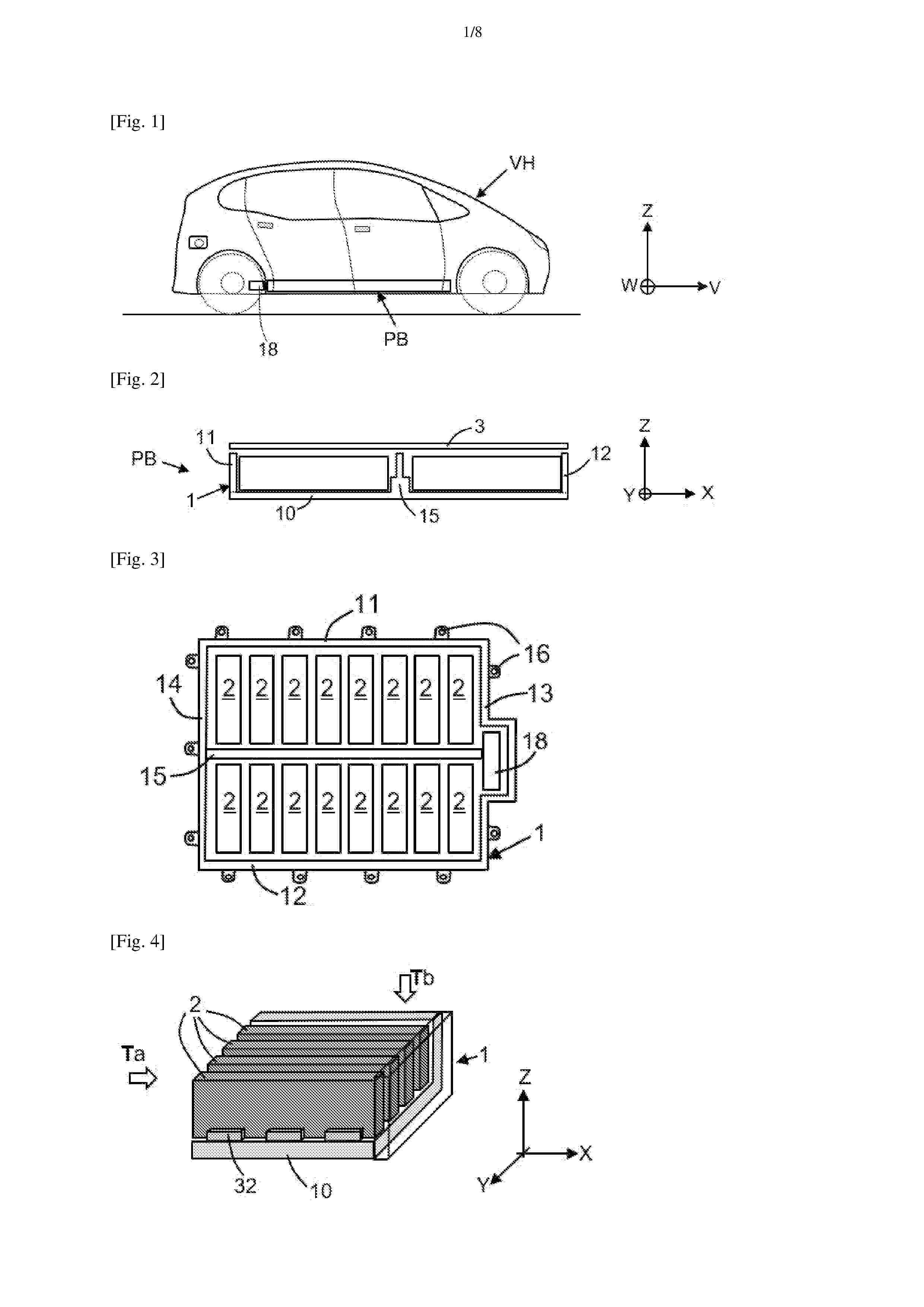
Pack batterie comprenant un bac batterie (1) comprenant un fond et des rebords montants, le fond étant équipé d’au moins un élément de guidage, tel qu’un rail ou des murets, étendu selon la direction longitudinale (X) et faisant saillie verticalement vers le haut à partir du fond, le pack batterie comprenant des modules de batterie électrique (2) amovibles, chaque module pouvant être individuellement inséré ou retiré du pack selon une direction d’insertion (T), chaque module inséré étant en interface de contact mécanique avec des éléments de guidage selon la direction transversale, avec un système de retenue agencé sur le bac pour maintenir le module en butée d’insertion le long de la direction d’insertion, et avec un système de connexion électrique configuré pour relier les bornes électriques du module à un collecteur formant un bus bar, l’établissement des contacts électriques étant réalisé de manière automatique par accouplement en fin d’insertion. Figure de l’abrégé : Fig. 2
Resumen de: FR3170118A1
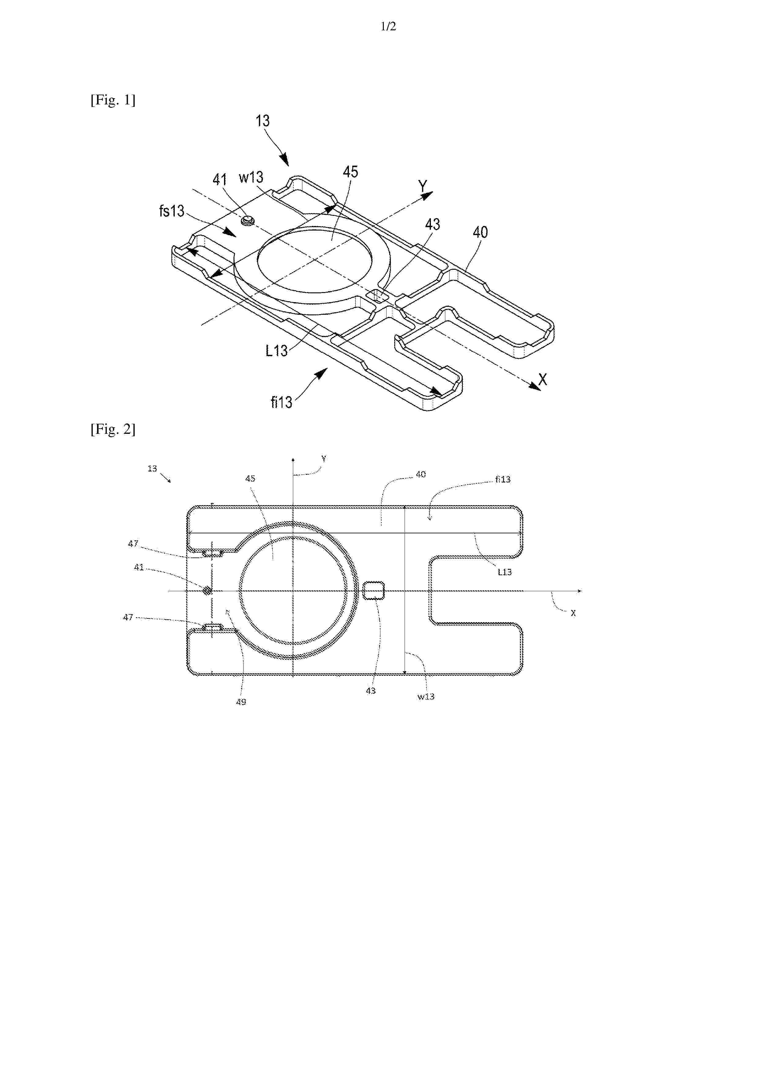
L’invention concerne un élément d’isolation (13) électrique destiné à être interposé entre un collecteur de courant (10) et un couvercle (6) d’une cellule de batterie (1) prismatique, ledit élément d’isolation (13) présentant une face inférieure (fi13) destinée à être tournée vers le collecteur de courant (10), et une face supérieure (fs13) destinée à venir en contact avec le couvercle (6) ; l’élément d’isolation (13) comprenant sur sa face supérieure (fs13), des éléments de positionnement (41, 43) en relief destinés à coopérer par complémentarité de forme avec des éléments complémentaires délimités par le couvercle (6) d’une manière bloquant une translation relative et une rotation relative entre l’élément d’isolation (13) et le couvercle (6). L’invention concerne également un ensemble (5) et une cellule de batterie (1) comprenant un tel élément d’isolation (13). Figure 1
Resumen de: FR3170125A1
L’invention concerne un organe d’espacement (15) destiné à être interposé entre un couvercle (6) et un terminal (2, 3) d’une cellule de batterie (1) prismatique, ledit organe d’espacement (15) comprenant un corps principal (60) et présentant une face inférieure (fi60) destinée à venir en contact avec le couvercle (6), et une face supérieure (fs60) destinée à venir en contact avec le terminal (2, 3) ; l’organe d’espacement (15) comprenant sur sa face inférieure (fi60), un élément de positionnement (67) en relief en forme de croix, destiné à coopérer par complémentarité de forme avec un organe de positionnement (14) délimité par le couvercle (6), d’une manière bloquant une translation relative et une rotation relative entre le couvercle (6) et l’organe d’espacement (15). L’invention concerne également un ensemble (5), et une cellule de batterie (1) comprenant un tel organe d’espacement (15). Figure 1
Resumen de: FR3170122A1
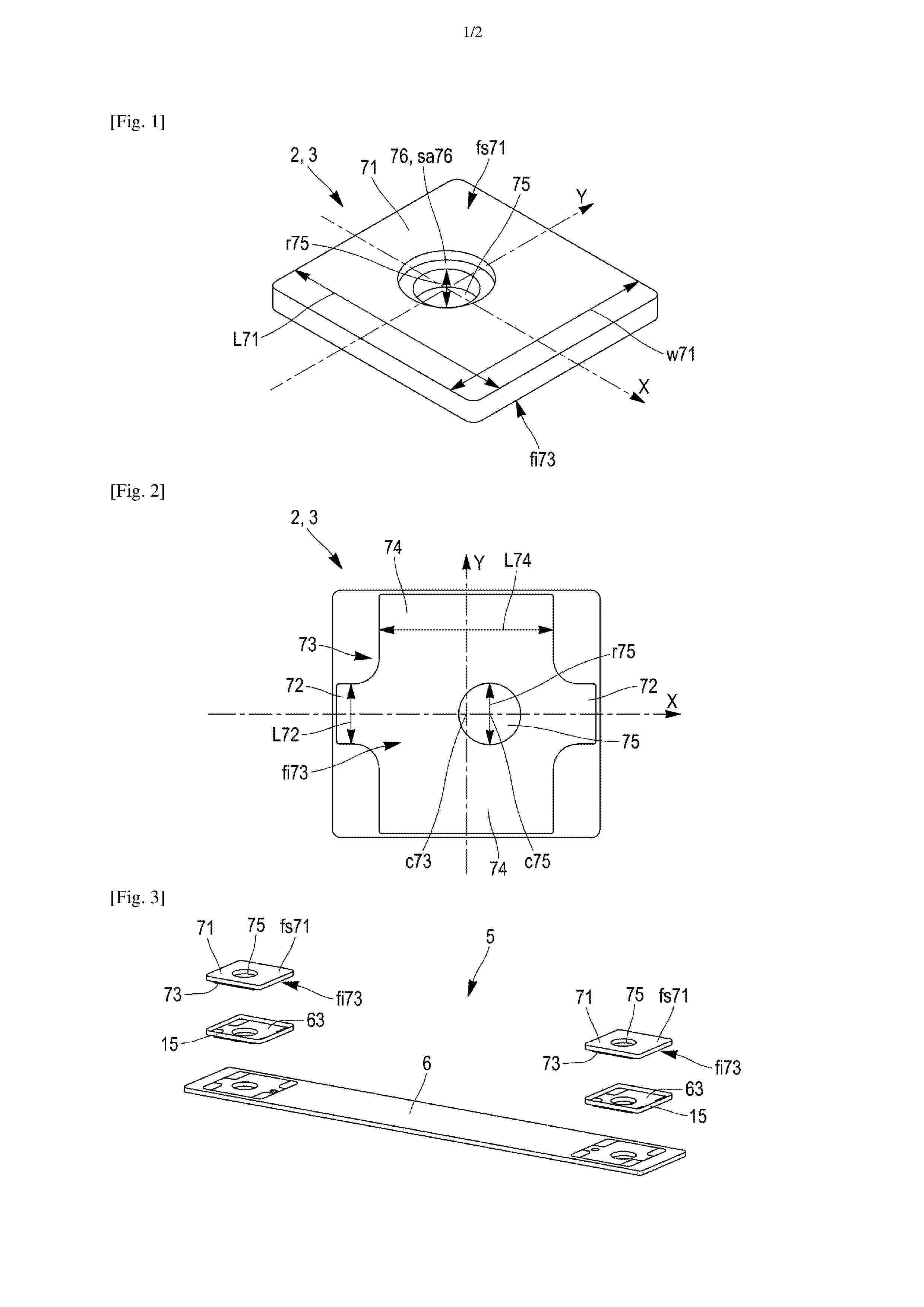
L’invention concerne un terminal (2, 3) pour cellule de batterie (1) destiné à être placé en connexion électrique avec un collecteur de courant (10) de la cellule de batterie (1), ledit terminal (2, 3) comprenant une plaque (71) et une empreinte (73) faisant saillie de la plaque (71) et en forme de croix, l’empreinte (73) est destinée à coopérer par complémentarité de forme avec une contre empreinte (63) délimitée par l’organe d’espacement (15), d’une manière bloquant une translation relative et une rotation relative entre le terminal (2, 3) et l’organe d’espacement (15). L’invention concerne également un ensemble (5), et une cellule de batterie (1) comprenant un tel terminal (2, 3). Figure 1
Resumen de: FR3170112A1
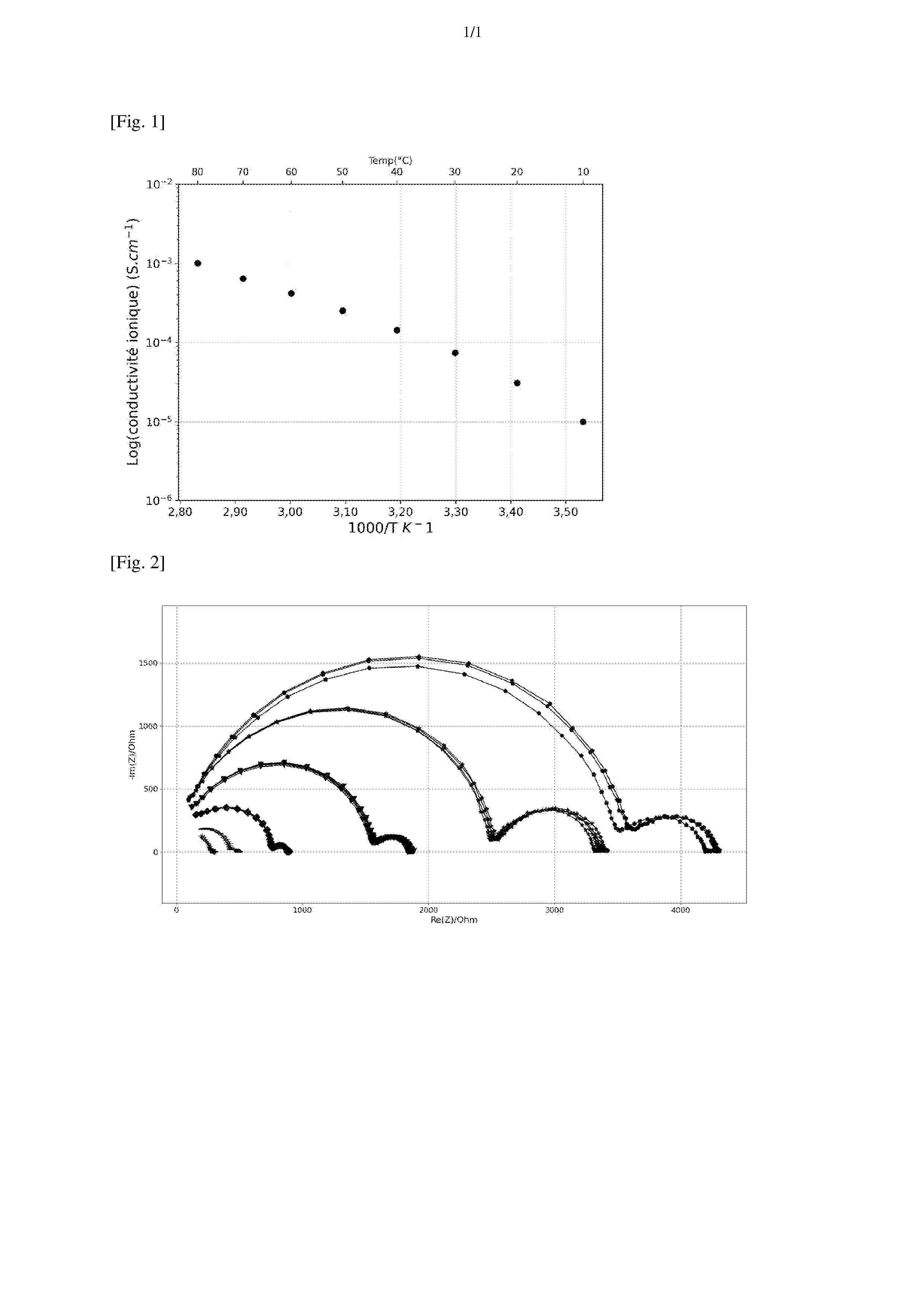
La présente invention concerne une composition électrolyte comprenant un sel de lithium, et un complexe à transfert de charge formé à partir d’un précurseur dudit complexe à transfert de charge, accepteur d’électrons, et d’un précurseur dudit complexe à transfert de charge, donneur d’électrons, ledit sel de lithium étant le (fluorosulfonyl)(trifluorométhanesulfonyl) imidure de lithium LiFTFSI, ledit précurseur dudit complexe à transfert de charge, accepteur d’électrons, étant la benzoquinone ou un de ses dérivés, et ledit précurseur dudit complexe à transfert de charge, donneur d’électrons, étant l’hydroquinone ou un de ses dérivés. Elle concerne également un procédé de préparation de ladite composition électrolyte, l’utilisation de ladite composition électrolyte dans une batterie rechargeable au lithium métal ou pour la préparation d’un électrolyte solide d’une batterie rechargeable au lithium métal, un électrolyte solide pour une batterie rechargeable au lithium métal comprenant ladite composition électrolyte, et une batterie rechargeable au lithium métal comprenant ledit électrolyte solide. Figure à publier : figure 1
Resumen de: FR3170113A1
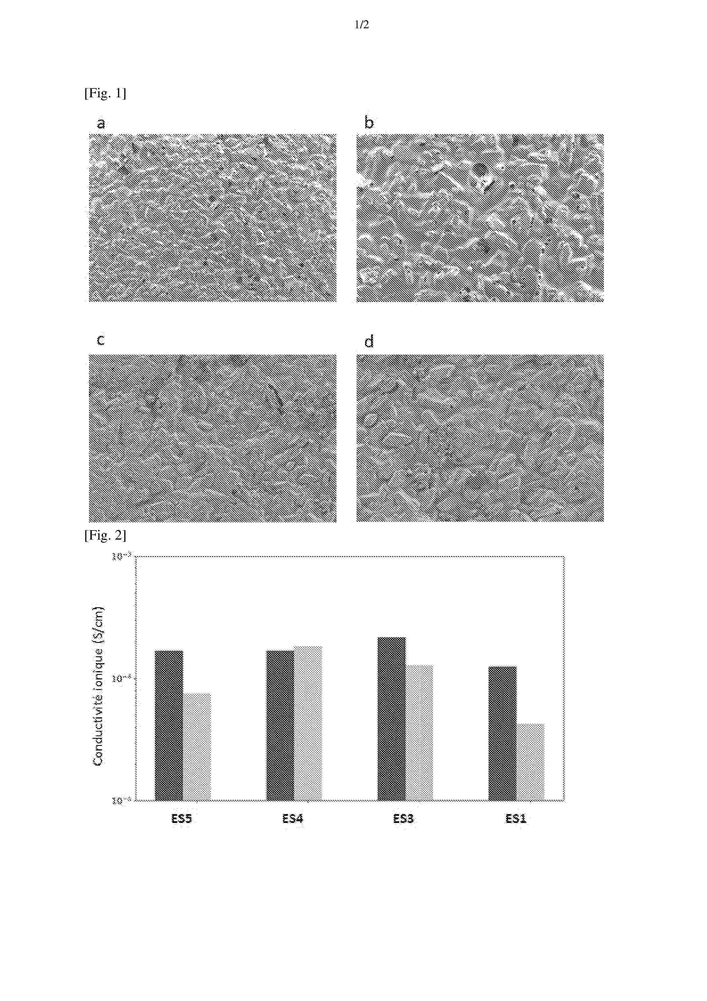
La présente invention concerne une composition électrolyte comprenant un sel de lithium, un complexe à transfert de charge formé à partir d’un précurseur dudit complexe à transfert de charge, accepteur d’électrons, et d’un précurseur dudit complexe à transfert de charge, donneur d’électrons, un polymère filmogène et un solvant. Elle concerne également un procédé de préparation de cette composition électrolyte, l’utilisation de ladite composition électrolyte pour la préparation d’un électrolyte solide sous la forme d’un film flexible, un procédé de préparation d’un électrolyte solide sous la forme d’un film par enduction de ladite composition électrolyte, l’électrolyte solide sous forme de film flexible susceptible d’être obtenu par la mise en œuvre de ce procédé, un procédé d’élaboration d’une batterie rechargeable au lithium métal comprenant un tel électrolyte solide et une batterie rechargeable au lithium métal, comprenant ledit électrolyte solide. Figure à publier : figure 2
Resumen de: FR3170012A1
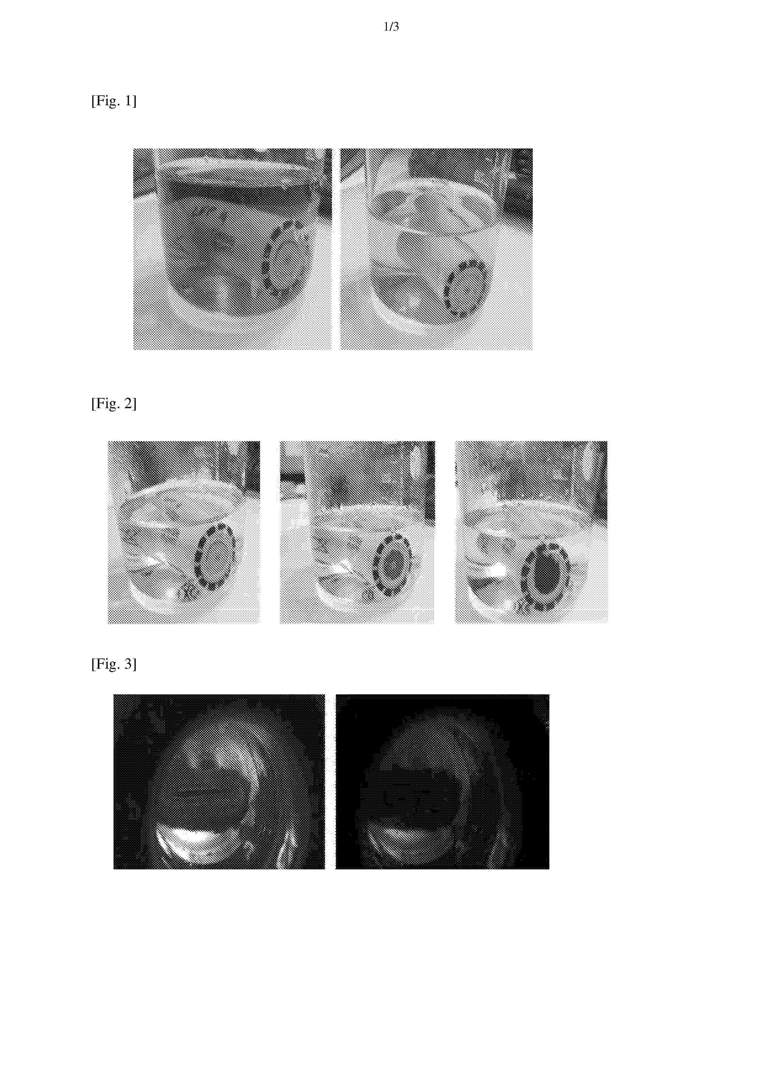
La présente invention concerne un procédé pour déterminer la tension entre les bornes d’un objet comprenant les étapes suivantes : (a) mettre en contact, sans connexion électrique, les bornes dudit objet avec une composition comprenant au moins un composé chimique apte à générer un signal optique lorsque soumis à une tension supérieure ou égale à une tension seuil, et (b) détecter un éventuel signal optique émis par le composé chimique moyennant quoi si un signal optique est détecté, la tension entre les bornes dudit objet est supérieure ou égale à la tension seuil. La présente invention concerne également un système électrochimique pour déterminer la tension entre les bornes d’un objet.
Resumen de: FR3169802A1
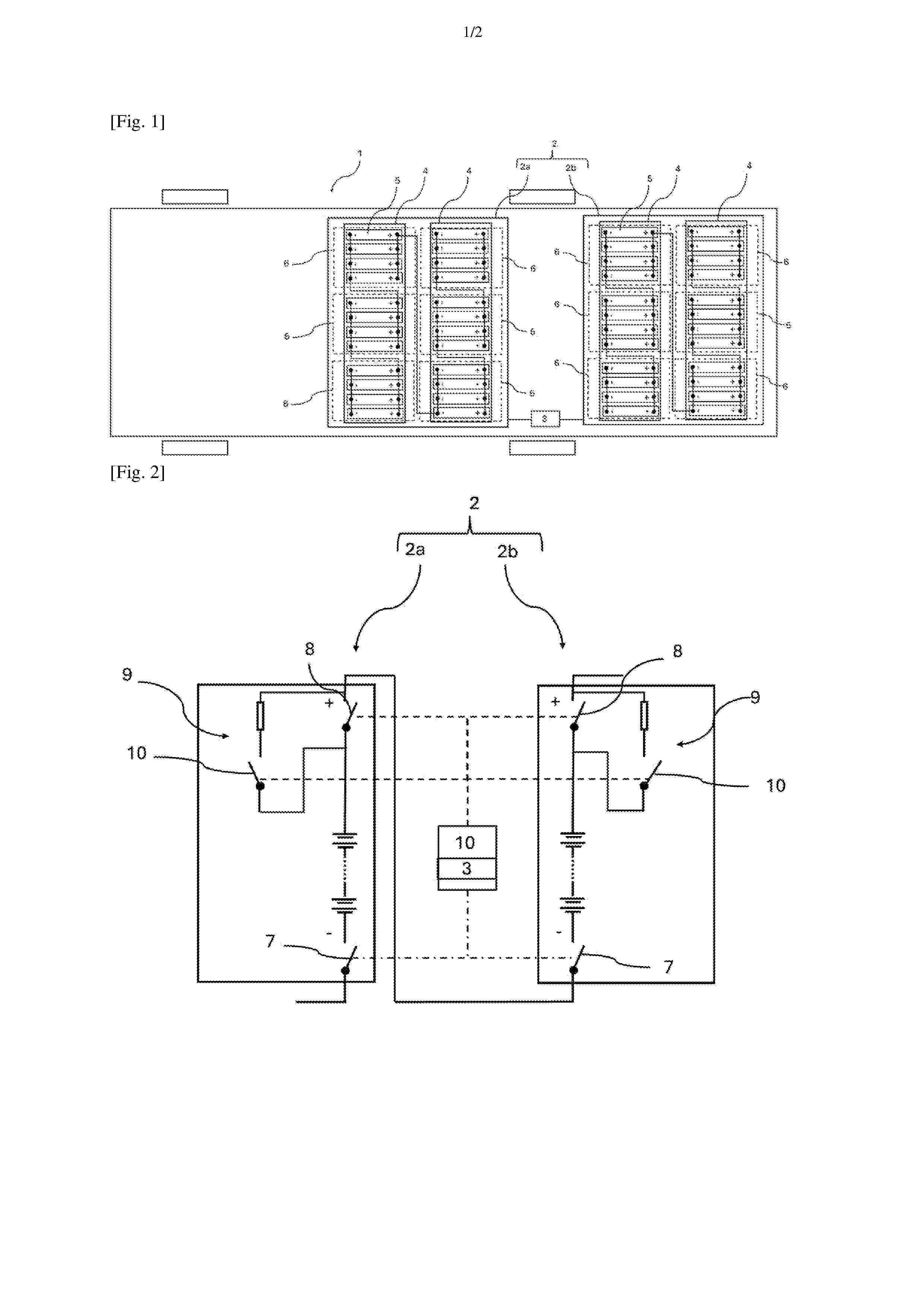
Un aspect de l’invention concerne un ensemble 2 de packs batteries 2a, 2b pour véhicule 1 automobile comportant au moins deux packs batteries 2a, 2b agencés pour alimenter un réseau électrique de puissance d’un véhicule 1, chaque pack batterie 2a, 2b comportant des modules 4 ainsi qu’un premier contacteur de puissance 7 et un deuxième contacteur de puissance 8 agencés pour isoler électriquement le pack batterie 2a, 2b, chaque module 4 comportant des cellules 5 électrochimiques, ledit ensemble 1 de packs batteries 2a, 2b étant remarquable en ce que les au moins deux packs batteries 2a, 2b sont électriquement connectés en série. Figure 1
Resumen de: FR3170117A1
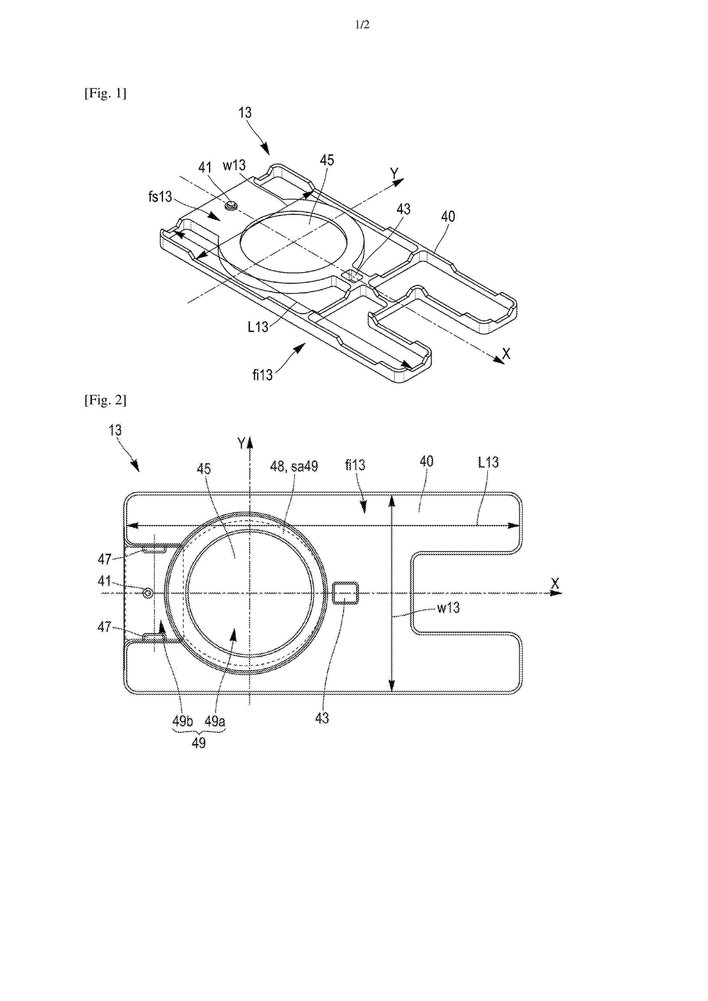
L’invention concerne un élément d’isolation (13) électrique destiné à être interposé entre un collecteur de courant (10) et un couvercle (6) d’une cellule de batterie (1) prismatique, ledit élément d’isolation (13) présentant une face inférieure (fi13) destinée à venir en contact avec le collecteur de courant (10), et comprenant sur sa face inférieure (fi13), des organes de positionnement (47) en relief, destinés à coopérer par complémentarité de forme avec le collecteur de courant (10) d’une manière bloquant une translation relative et une rotation relative entre le collecteur de courant (10) et l’élément d’isolation (13). L’invention concerne également un ensemble (5) et une cellule de batterie (1) comprenant un tel élément d’isolation (13). Figure 2
Resumen de: FR3170011A1
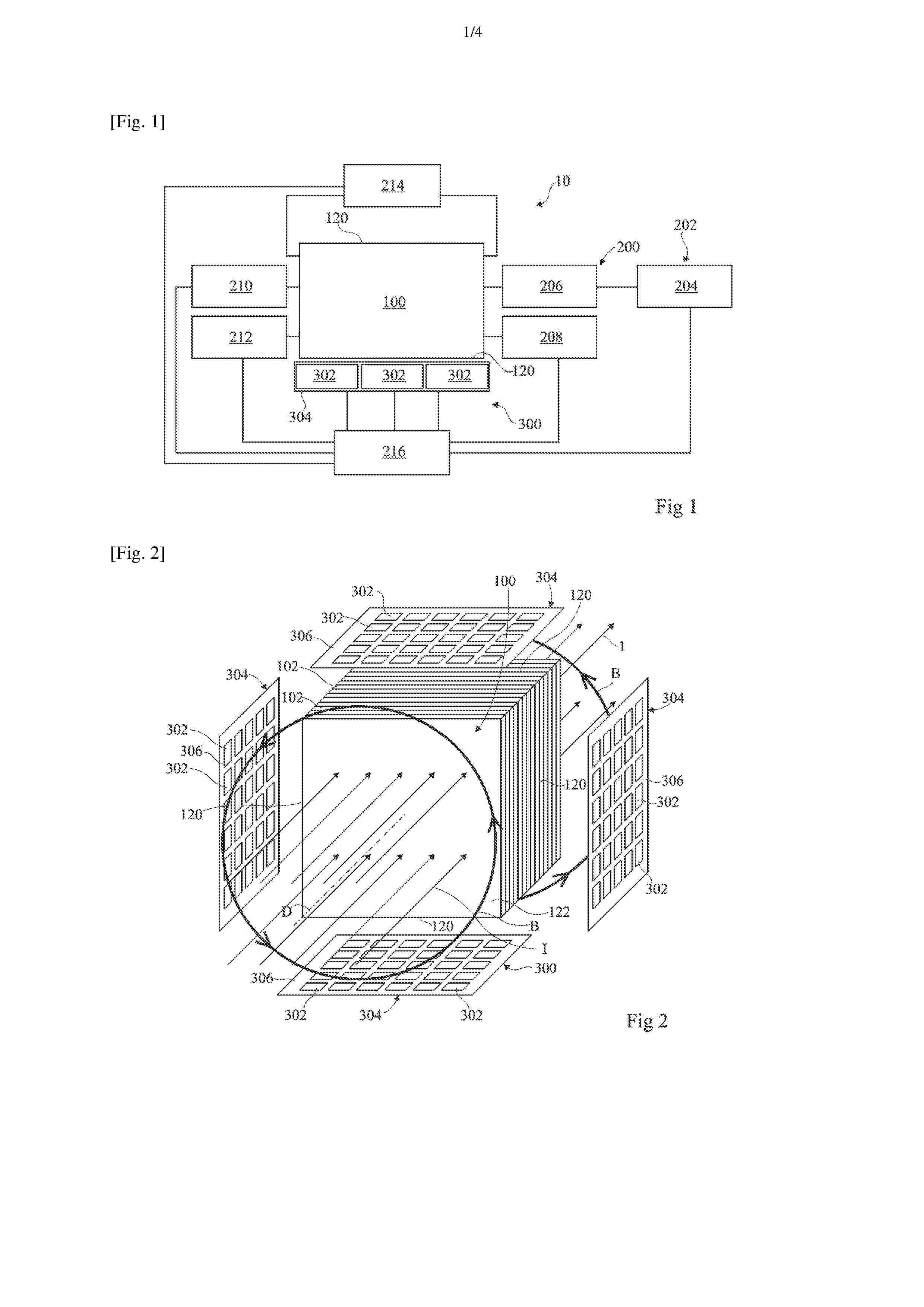
Dispositif et procédé de mesure d'un champ magnétique émis par un objet La présente description concerne un dispositif (300) de mesure d'un champ magnétique (B) émis par un objet (100) comprenant un capteur matriciel (304) comprenant une matrice de capteurs magnétiques (302) configurés pour acquérir des mesures successives du champ magnétique, une charge commandable (314) destinée à être connectée électriquement à l'objet (100), et un module (216) configuré pour commander la charge commandable (314) pour faire varier le courant circulant dans l'objet (100) au cours des acquisitions des mesures successives du champ magnétique et pour recevoir les mesures successives du champ magnétique. Figure pour l'abrégé : Fig. 1
Resumen de: FR3170127A1
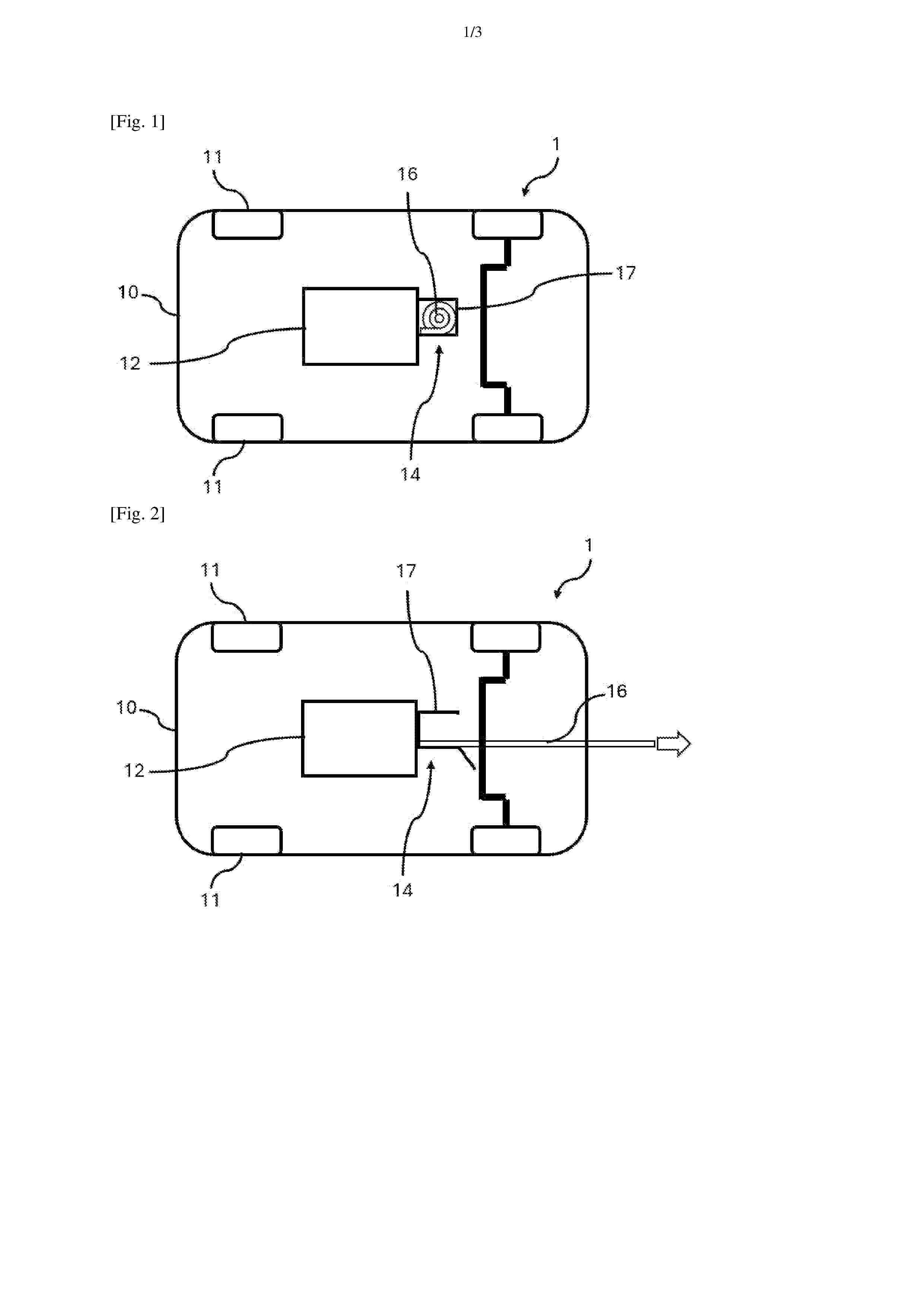
Système d’évacuation d’un fluide pour un agencement pour véhicule automobile Agencement (1) pour un véhicule (10) automobile électrique ou hybride, l’agencement (1) comprenant une batterie (12), notamment une batterie (12) au lithium, l’agencement (1) étant caractérisé en ce qu’il comprend un système d’évacuation (14) d’un fluide, notamment d’un gaz, le système d’évacuation (14) étant destiné à être monté sur la batterie (12) de l’agencement (1), le système d’évacuation (14) comprenant une structure tubulaire (16) configurée pour se déployer longitudinalement entre une configuration escamotée et une configuration déployée lorsqu’un seuil de pression prédéterminé est franchi à l’intérieur de la batterie (12) agencée en amont de la structure tubulaire (16) du système d’évacuation (14). Figure pour l’abrégé : Fig.1
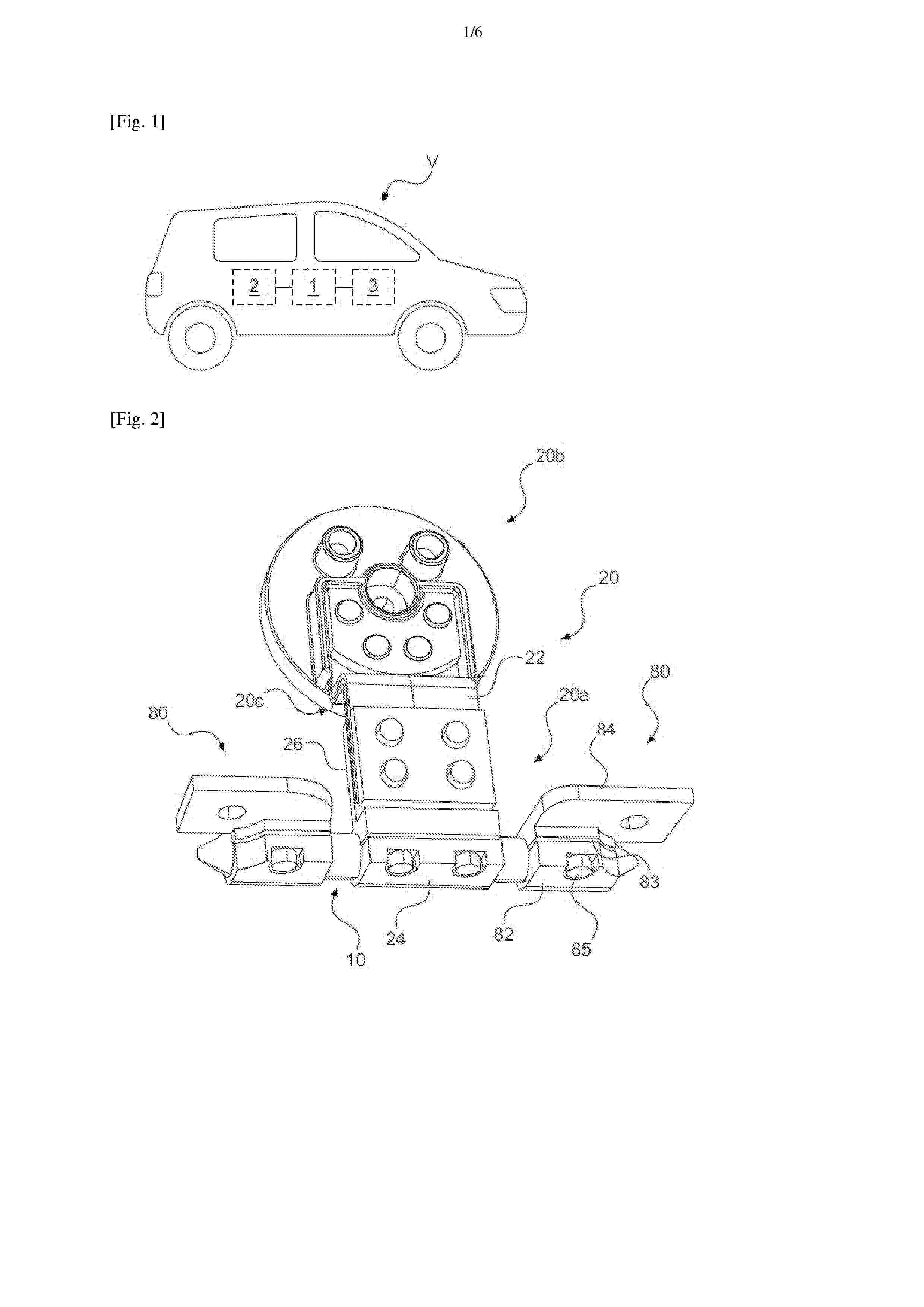
Resumen de: FR3169784A1
Dispositif de dissipation thermique, notamment pour véhicule automobile, ledit dispositif comprenant un caloduc (10) configuré pour un échange thermique entre, d’une part, une source chaude comprenant un organe électrique, et, d’autre part, une source froide, ledit dispositif comprenant en outre : - un premier organe d’interface thermique (20) en contact avec le caloduc (10) et destinée à être en relation d’échange thermique avec l’une desdites sources chaude ou froide, - un deuxième organe d’interface thermique (80) en contact avec le caloduc (10) et destinée à être en relation d’échange thermique avec l’autre desdits sources chaude ou froide, ledit premier organe d’interface thermique (20) présentant une base (20a) en contact avec le caloduc (10), une tête (20b) destinée à être en relation d’échange thermique avec ladite source chaude ou froide en cause et une zone flexible (20c) située entre ladite base (20a) et ladite tête (20b). Figure pour l’abrégé : Figure 2
Resumen de: FR3170126A1
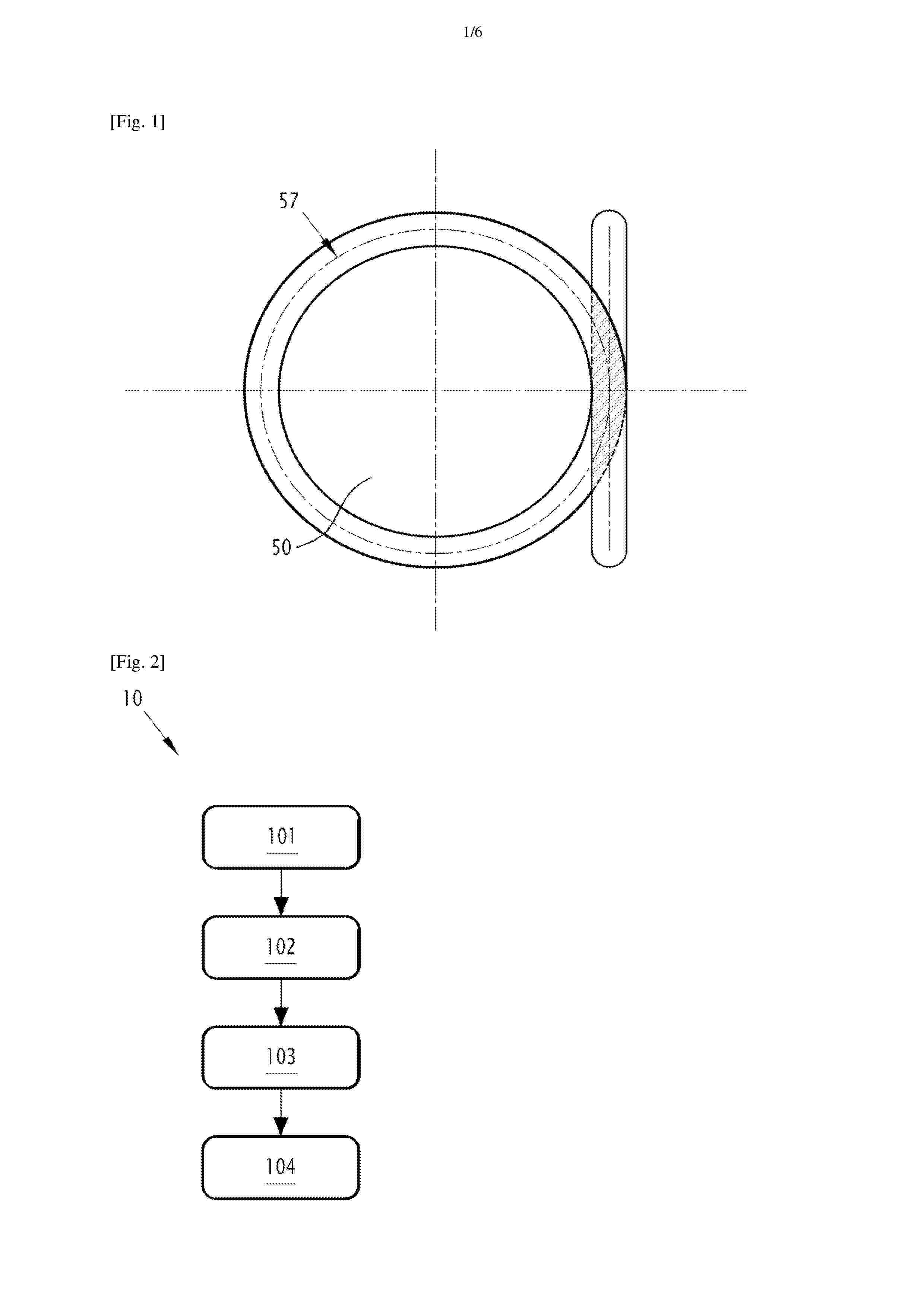
Soudage de scellement d'un trou de remplissage d'électrolyte pour une cellule de batterie, et cellule de batterie associée L'invention concerne un processus de fabrication d'une cellule électrochimique (17), le processus (10) comprenant la fourniture d'au moins un assemblage sec (18), le remplissage d'une solution électrolytique (35) à l'intérieur de l'assemblage sec (18) à travers un trou de remplissage (15), la disposition d'une plaque de disque (50) sur la plaque de recouvrement supérieure (32) afin de couvrir le trou de remplissage (15), puis le soudage du bord de la plaque de disque (50) avec une partie de la plaque de recouvrement supérieure (32) à l'aide d'un faisceau laser (55) qui suit un modèle spécifique comprenant : un segment de pré-soudage (59) jusqu'à un premier point de bord (62) de la plaque de disque (50), le segment de pré-soudage (59) s'écartant de l'axe tangent à la plaque de disque (50) au niveau du premier point de bord (62), un cercle complet (65) du cordon de soudage principal couvrant la totalité des bords de la plaque de disque, et un segment de post-soudage s'écartant de l'axe tangent à la plaque de disque (50) au niveau du premier point de bord (62). Figure : Figure 6
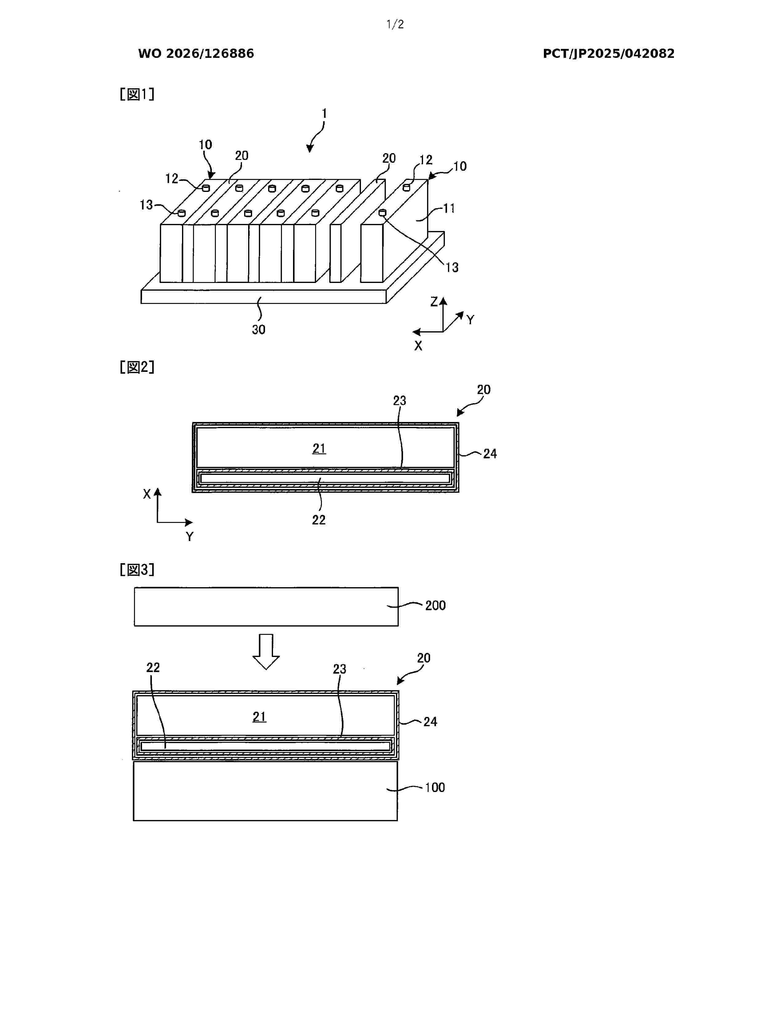
Resumen de: WO2026126886A1
Provided is a spacer capable of suppressing heat transfer and maintaining the shape of the spacer. This spacer is disposed between two power storage elements disposed adjacent to each other, and has an elastic member and a heat insulating member disposed next to each other in the array direction of the power storage elements. The elastic member is an aggregate in which heat-resistant particles, reinforcement fibers, and elastic particles that are rubber particles and/or resin particles are dispersed, and has pores. The heat insulating member can be covered with a first exterior material. The elastic member and the heat insulating member covered with the first exterior material can be covered with a second exterior material. A molded body formed from inorganic particles can be used as the heat insulating member.
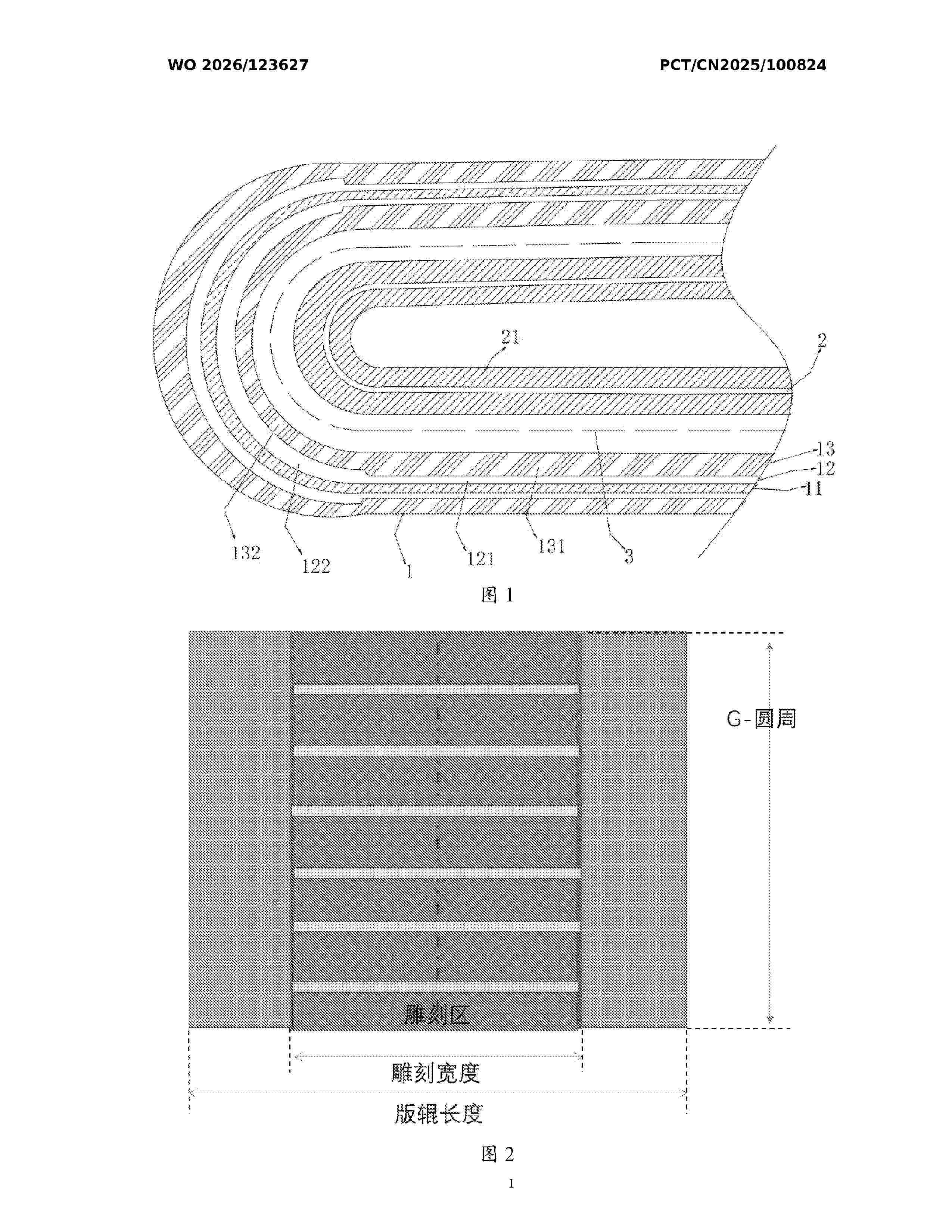
Resumen de: WO2026123627A1
The present application belongs to the technical field of batteries, and discloses a secondary battery and an electrical apparatus. The secondary battery comprises a wound battery cell, the wound battery cell comprising a flat region and a corner region, and the wound battery cell comprising a positive electrode sheet, a negative electrode sheet, and a separator between the positive electrode sheet and the negative electrode sheet. The positive electrode sheet comprises a positive electrode current collector, and a flame retardant layer and a positive electrode active material layer which are sequentially disposed on at least one surface of the positive electrode current collector. In the present application, a thickness relationship between the flame retardant layer and the positive electrode active material layer in the flat region and the corner region is controlled, so that the phenomenon of lithium precipitation at a corner can be significantly ameliorated.
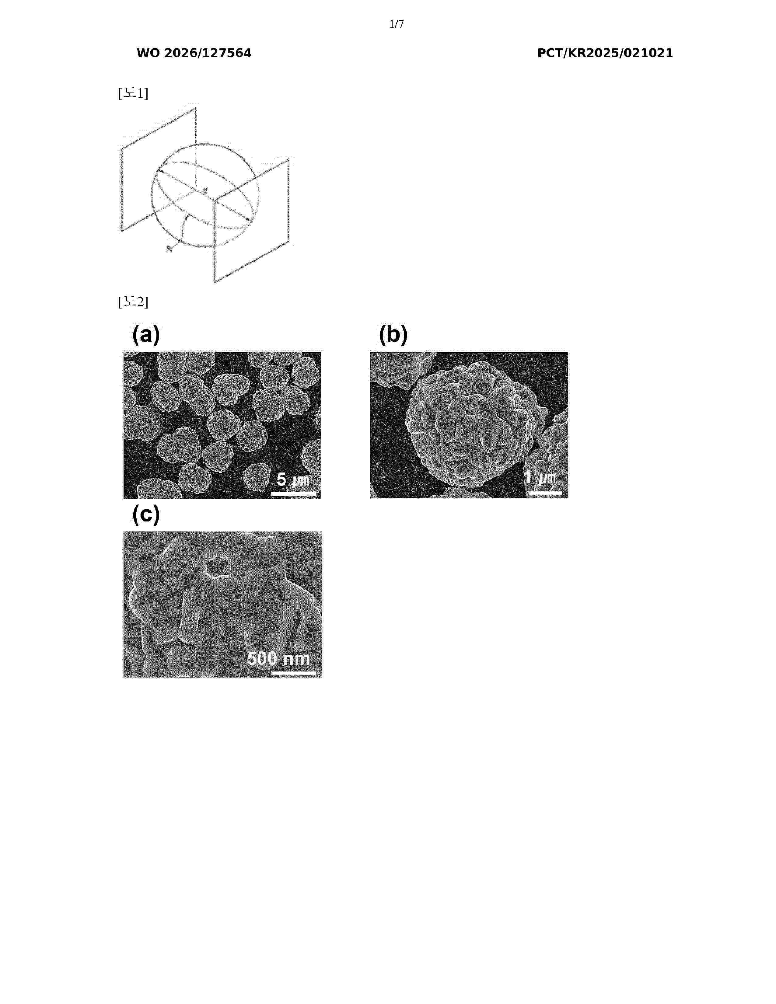
Resumen de: WO2026127564A1
Provided are a positive electrode active material, a method for preparing same, and a positive electrode comprising same. The positive electrode active material includes secondary particles in which a plurality of primary particles are aggregated, wherein the primary particle includes a core portion including a lithium transition metal oxide and a surface portion including a first element, and the first element is selected from the group consisting of Y, Zr, B, Ti, W, Nb, Sr, Mo, Mg, P, V, Ta, Ga, Ca, Si, La, and combinations thereof. Both capacity characteristics and stability can be improved through the preparation of the positive electrode active material, and a battery including the positive electrode active material may exhibit improved rate characteristics and lifespan characteristics.
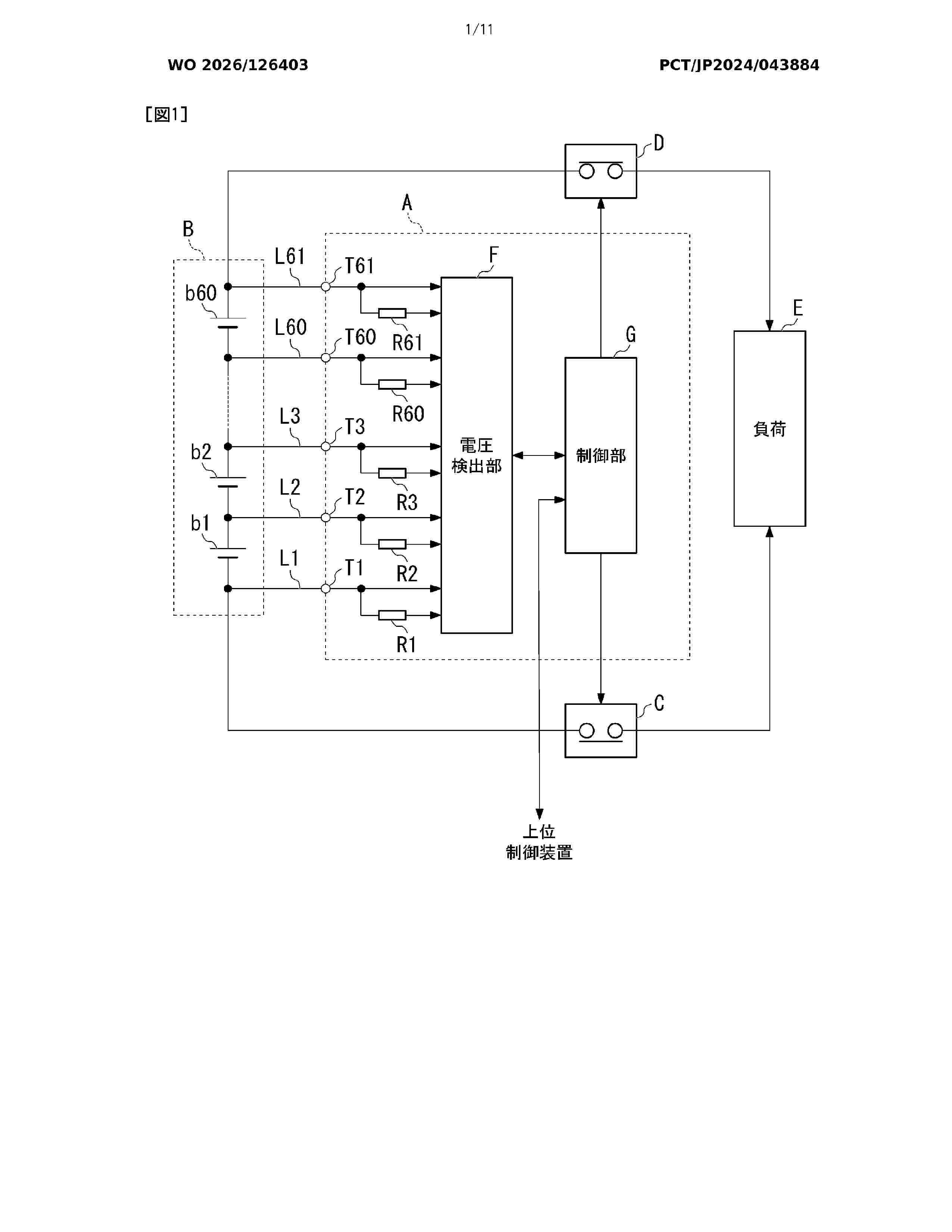
Resumen de: WO2026126403A1
The purpose of the present disclosure is to provide a monitoring device and a power supply system capable of evaluating the validity of a battery. In order to achieve the above purpose, the present disclosure employs, as the solution, a monitoring device for monitoring a battery provided with a plurality of battery cells electrically connected in series, the monitoring device comprising: a voltage detection unit that is electrically connected to the plurality of battery cells via a predetermined voltage detection line and that detects electrode voltages of the plurality of battery cells; a plurality of discharge circuits that forcibly discharge the plurality of battery cells; and an evaluation unit that calculates, as a path resistance value, a resistance value of the voltage detection line on the basis of the electrode voltages when specific battery cells are forcibly discharged by the plurality of discharge circuits and the electrode voltages when the battery cells are not forcibly discharged, and evaluates the validity of the battery on the basis of the path resistance value.
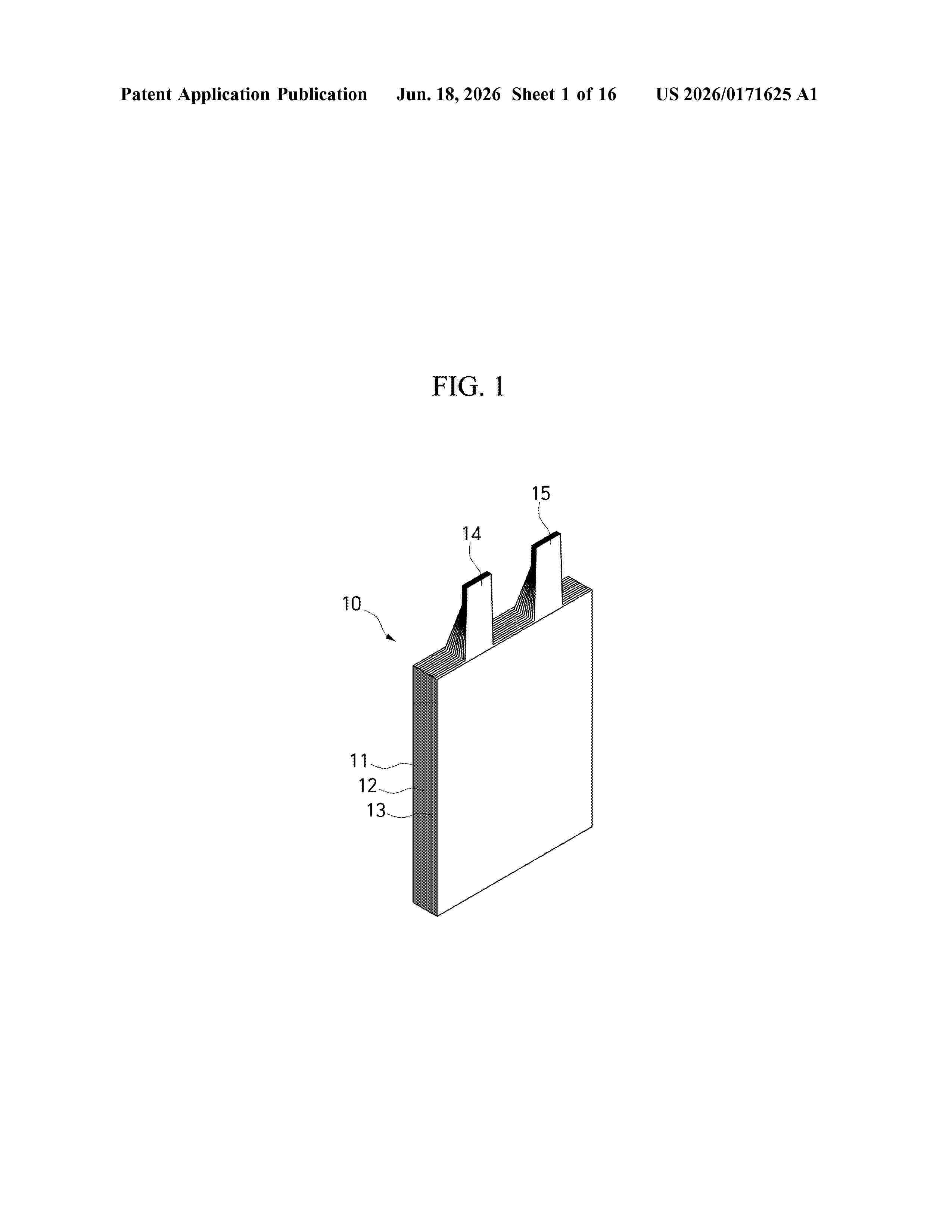
Resumen de: US20260171625A1
0000 The present disclosure relates to a secondary battery having electrode plates made of composite substrates and a manufacturing method that facilitates the welding of a strip conductor. According to an aspect of the present disclosure, there is provided a secondary battery including an exterior material; an electrode assembly accommodated in the exterior material including an electrode plate in which a coated portion coated with an electrode material and an uncoated portion which is not coated with the electrode material are formed on a composite substrate including a polymer layer and a conductive layer, a conductive plate attached to the conductive layer of the uncoated portion of the electrode plate included in the electrode assembly, and a strip conductor welded to the conductive plate.
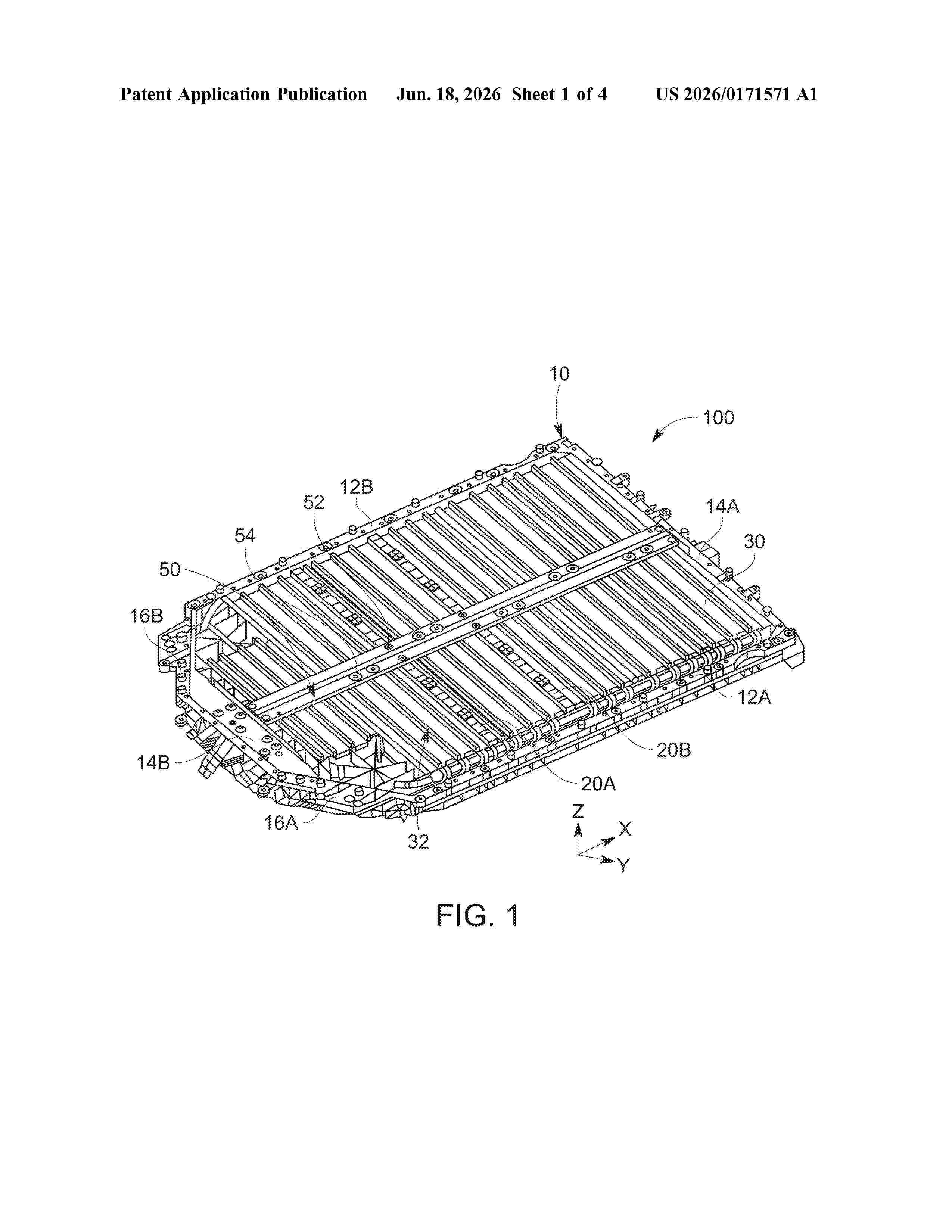
Resumen de: US20260171571A1
0000 A carrier framework for a battery pack includes: a frame including two pairs of opposing side beams; a cross beam connecting a first pair of the opposing side beams of the frame; and a stiffening beam fixed to a second pair of the opposing side beams of the frame and to the cross beam.
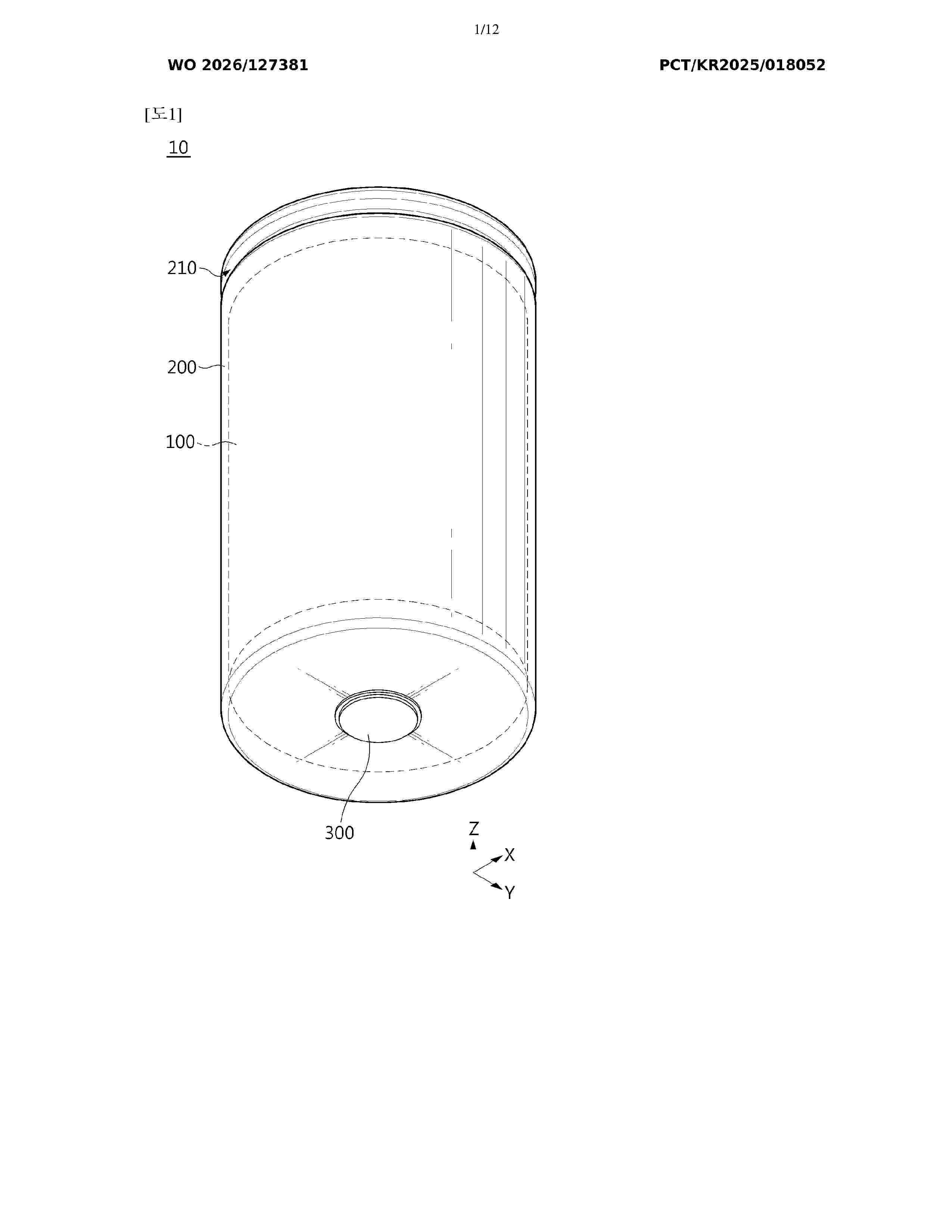
Resumen de: WO2026127381A1
The battery cell sizing device according to the present invention is a battery cell sizing device configured to be able to perform a sizing process by compressing a can housing of a battery cell in a vertical direction, the battery cell sizing device comprising: a support pusher supporting the lower portion of the can housing in the upward direction in a state where the support pusher is not in contact with a rivet terminal protruding from the lower portion of the can housing; a lifting pusher for pressing the lower portion of the can housing in the upward direction; a lowering pusher for pressing the upper portion of the can housing in the downward direction; and a beading guide member having an insertion support part of which at least a portion is inserted into a beading part of the can housing to be able to support at least a portion of the beading part, and an elastic support part elastically supporting the insertion support part in the vertical direction.
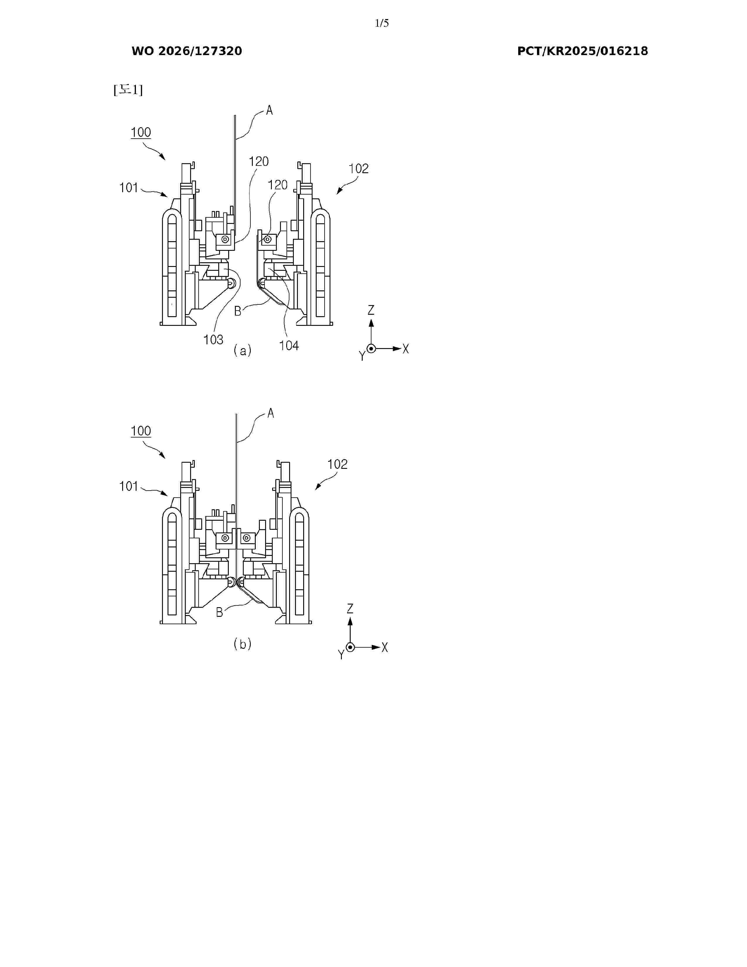
Resumen de: WO2026127320A1
According to exemplary embodiments of the present invention, an electrode splicing device is provided. The electrode splicing device comprises: a first splicing unit capable of gripping a trailing end part of a running electrode sheet; a second splicing unit which is positioned to face the first splicing unit and which can grip a leading end part of a standby electrode sheet; and a line contact type pressing unit for bonding, using tape, the trailing end part of the running electrode sheet and the leading end part of the standby electrode sheet. In addition, the present invention provides an electrode splicing method using the electrode splicing device.
Resumen de: DE102024138231A1
Bereitgestellt wird eine Batteriemodulstruktur, aufweisend ein als geschlossene Hülle gebildetes Foliensystem mit vorgegebenen Abmessungen, wobei das Foliensystem derart gebildet ist, dass es innerhalb der Hülle einen hohlen Raum zur Aufnahme eines Materials bereitstellt, und dass in einer Oberseite der Hülle mehrere Aufnahmebereiche zur Aufnahme jeweils einer Batterie-Zelle vorgesehen sind, wobei das Foliensystem ferner mindestens eine Einfüllöffnung zum Einbringen des Materials in den hohlen Raum aufweist.
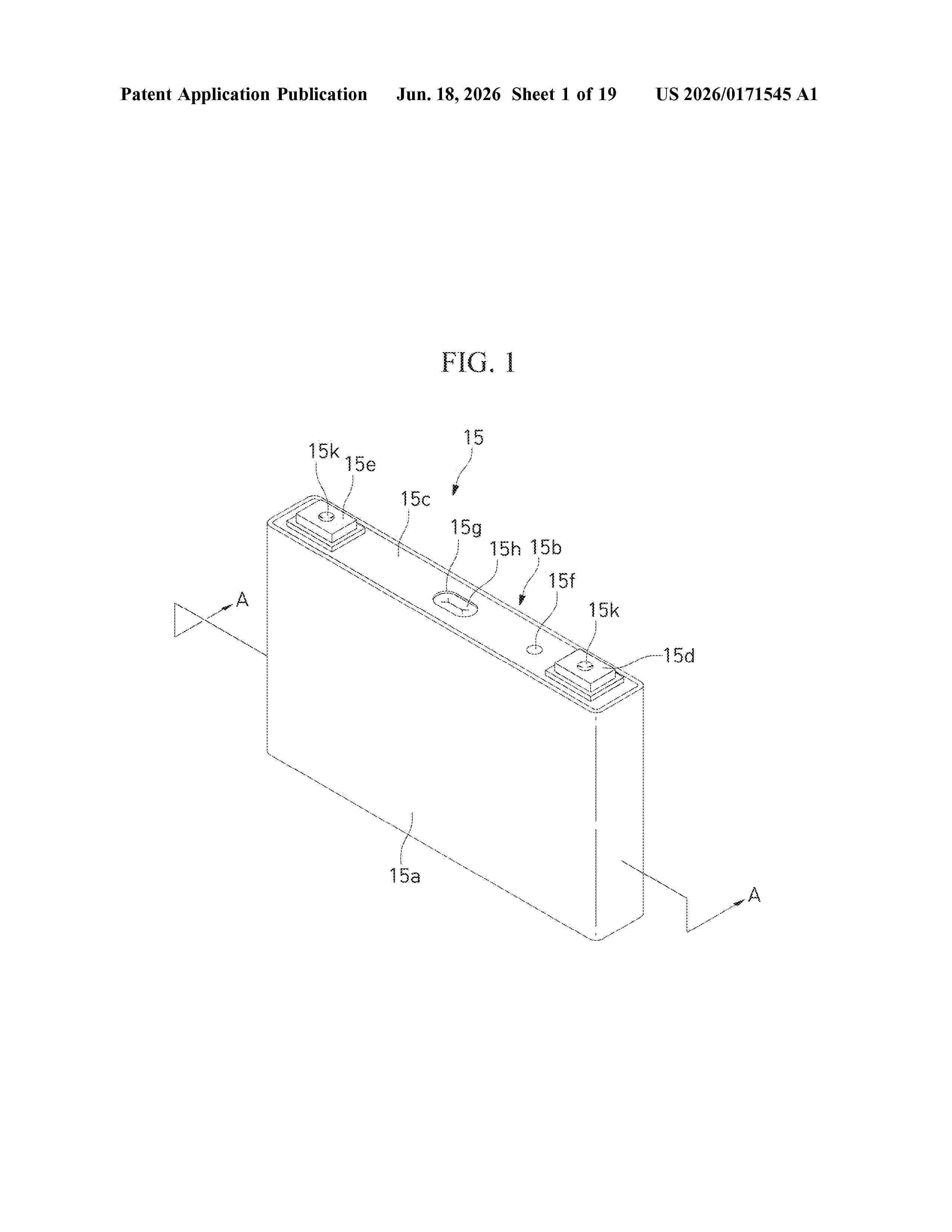
Resumen de: US20260171545A1
0000 A secondary battery module includes: a module case having an inflow passage and an outflow passage configured to allow air to pass therethrough; a plurality of battery cells in the module case; and a heat dissipation structure in close contact with at least one of the battery cells and configured to cool the at least one of the battery cells through heat exchange with the air passing through the module case.
Nº publicación: DE102024138076A1 18/06/2026
Solicitante:
STIHL AG & CO KG ANDREAS [DE]
Andreas Stihl AG & Co. KG
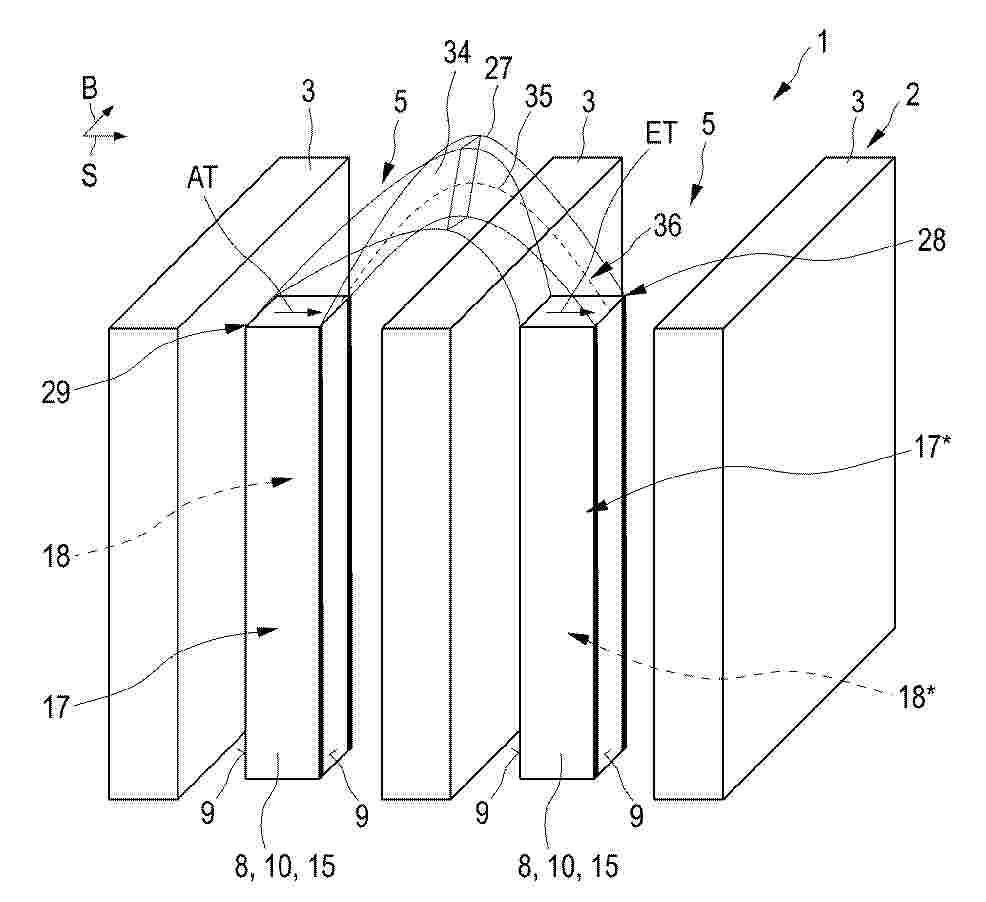
Resumen de: DE102024138076A1
Die Erfindung betrifft einen Batteriepack (1) für ein Bearbeitungssystem (100), wobei der Batteriepack (1) eine Zellanordnung (2) und eine von Temperierungsfluid (TF) durchfließbare Umlenkeinrichtung (27) aufweist, wobei die Umlenkeinrichtung (27) dazu angepasst ist, die Umlenkeinrichtung (27) durchfließendes Temperierungsfluid (TF) derart umzulenken, dass ein Ausgangs-Temperaturgradient (AT) des an dem Fluidausgang (29) ausfließenden Temperierungsfluids (TF) und ein Eingangs-Temperaturgradient (ET) des an dem Fluideingang (28) einfließenden Temperierungsfluids (TF) im Wesentlichen gleichgerichtet orientiert sind.
 BOPI
BOPI
 Sede Electrónica