Si deseas distinguir tus productos, servicios o ambos de los de otra empresa, es posible que necesites una marca o nombre comercial. Descubre qué son, en qué consiste su procedimiento de registro y qué implica.

Información sobre los plazos de presentación de solicitudes de transformación de marcas de la Unión Europea en marca nacional española. Más información


Si tienes un nuevo dispositivo, producto o procedimiento que resuelva un problema técnico o tenga una ventaja práctica, existen distintas formas de protegerlo en España y en otros países. Descubre cómo hacerlo.

¿Tu innovación reside en la estética, la ornamentación o la apariencia de tu producto? Protégela mediante un diseño industrial. Descubre qué derechos confiere el registro y cómo realizar la tramitación.

Las indicaciones geográficas protegen el nombre de un producto originario de una zona geográfica, a la cual le debe una determinada calidad, reputación u otra característica. Descubre qué son, en qué consiste su procedimiento de registro y qué beneficios conceden.

Las patentes publicadas en todo el mundo son una valiosa fuente de información científica, técnica y comercial.

Si eres emprendedor/a o una empresa y quieres potenciar y mejorar la rentabilidad de tu negocio protegiendo de forma adecuada los activos intangibles de tu organización, en este espacio encontrarás lo necesario.


 575
resultados
575
resultados
 Última actualización
14/09/2026 [07:52:00]
Última actualización
14/09/2026 [07:52:00]


 Resultados 25 a 50 de 575

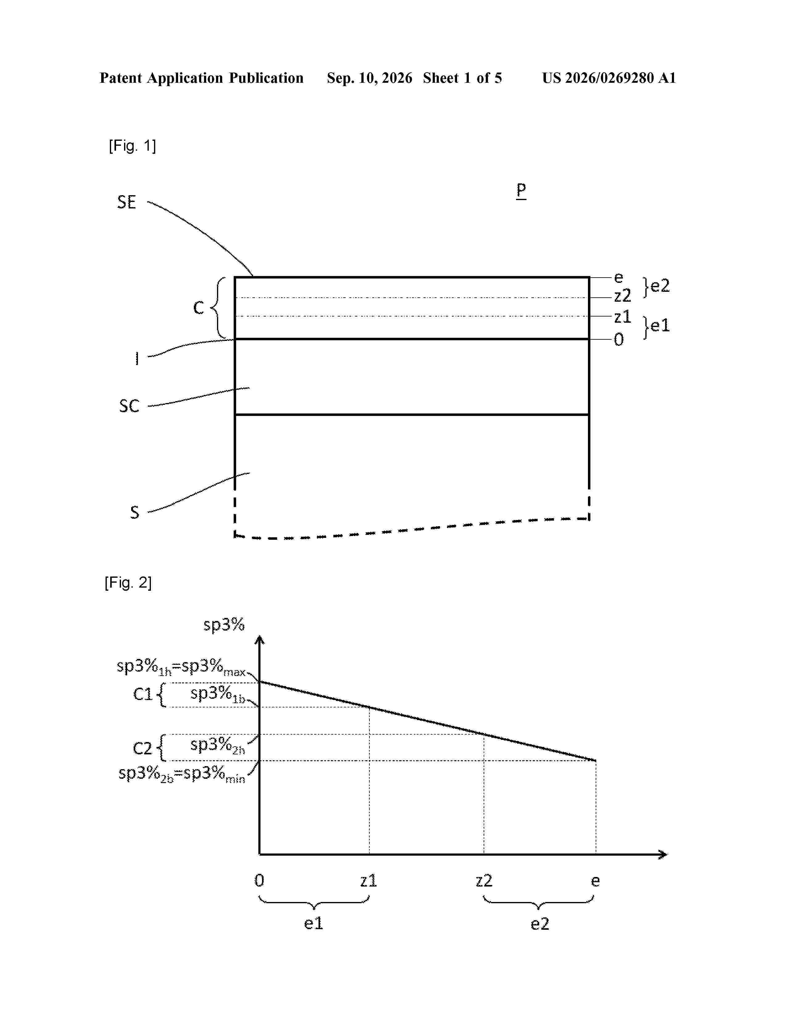
Resumen de: US20260269280A1
A part includes comprising a metal substrate and a layer of amorphous carbon-based material having sp2 hybridised bonds and sp3 hybridised bonds. The layer has a first content of sp3 hybridised bonds on the substrate side, anda second content of sp3 hybridised bonds on the side of an external surface of the layer,the first content being greater than the second content.An average content within the layer of sp3 hybridised bonds is between 5% and 65%and in that the content of sp3 hybridised bonds evolves continuously within the layer.

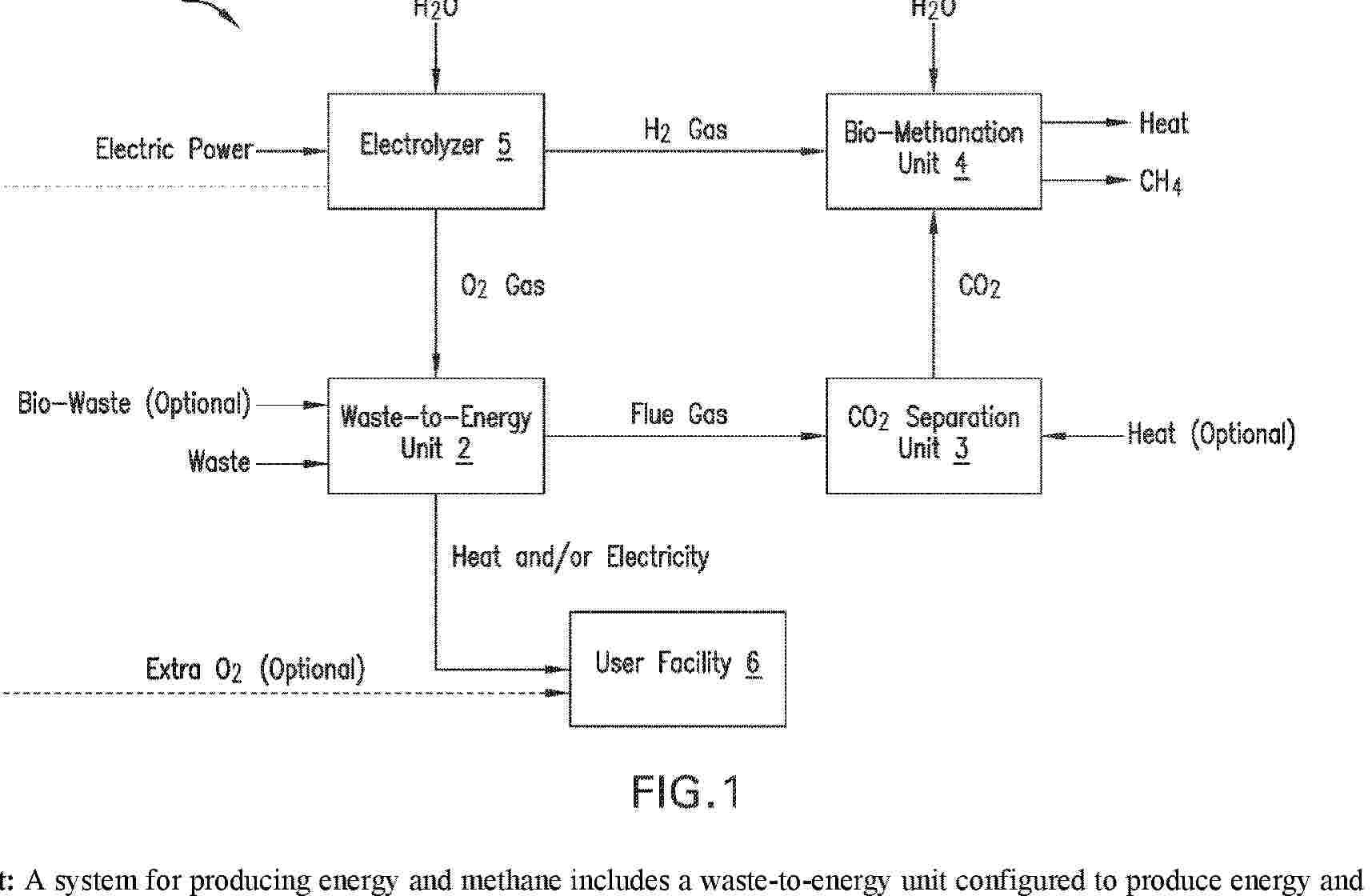
Resumen de: AU2025224758A1
A system for producing energy and methane includes a waste-to-energy unit configured to produce energy and a flue gas by combusting waste and an oxidizing agent having oxygen and a carbon dioxide (CO2) separation unit configured to separate CO2 from the flue gas to provide separated CO2. The system also includes a bio-methanation unit configured to generate methane (CH4), heat, and water using the separated CO2 received from the CO2 separation unit and received hydrogen (H2) gas. The system further includes an electrolyzer coupled to a source of water (H2O) and an electric power source supplying electricity and configured to split the H2O to generate the oxygen used in the oxidizing agent and the H2 gas used in the bio-methanation unit.
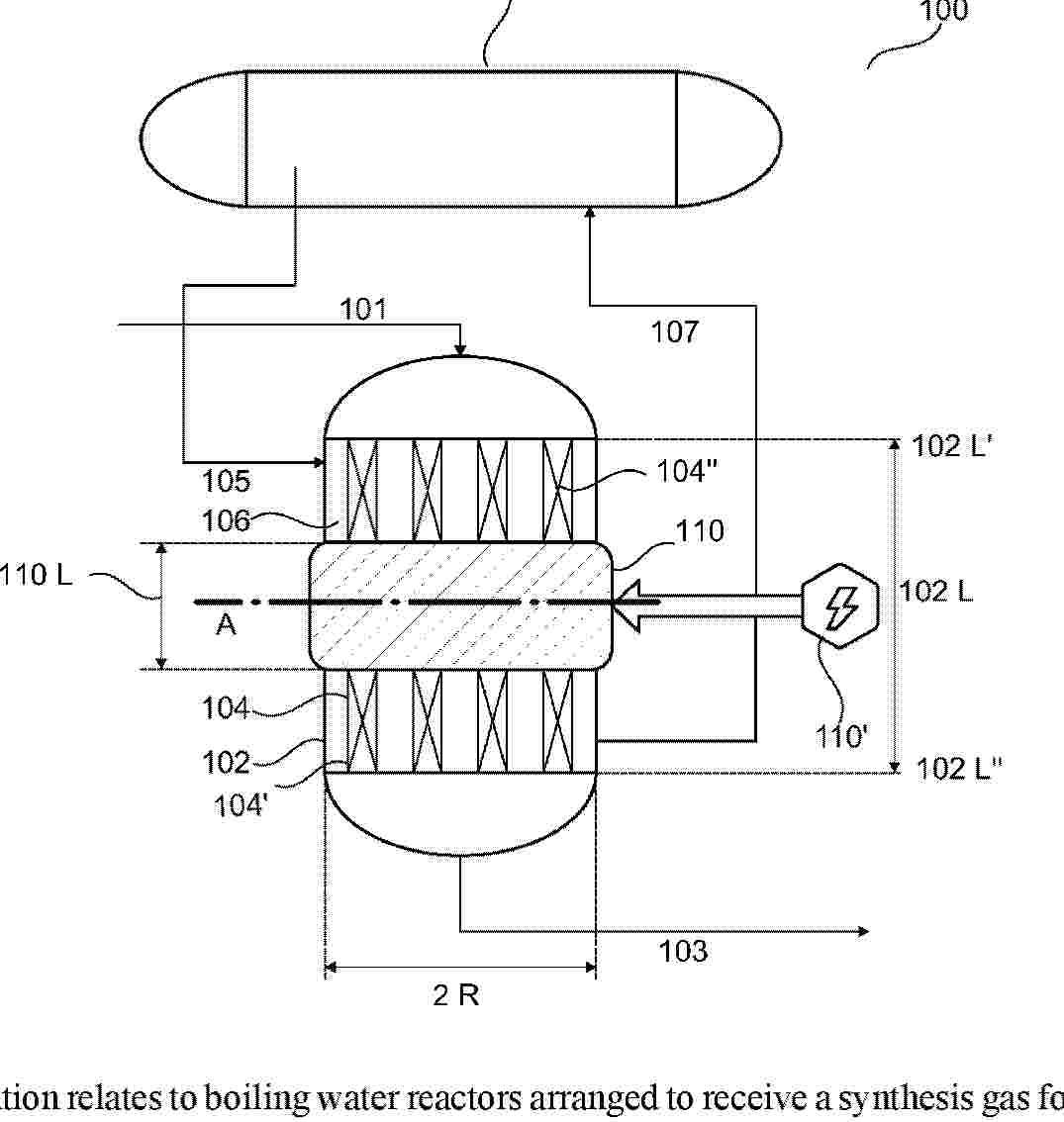
Resumen de: AU2025230555A1
The present invention relates to boiling water reactors arranged to receive a synthesis gas for producing raw gas products, such as a raw methanol product, particularly for transient operation, such as where the synthesis gas is at least partly provided by producing hydrogen by electrolysis of water or steam. Embodiments of the invention include a boiling water reactor, a method of revamping an existing boiling water reactor, and a process for producing raw gas product, such as raw methanol product, utilizing the boiling water reactor.
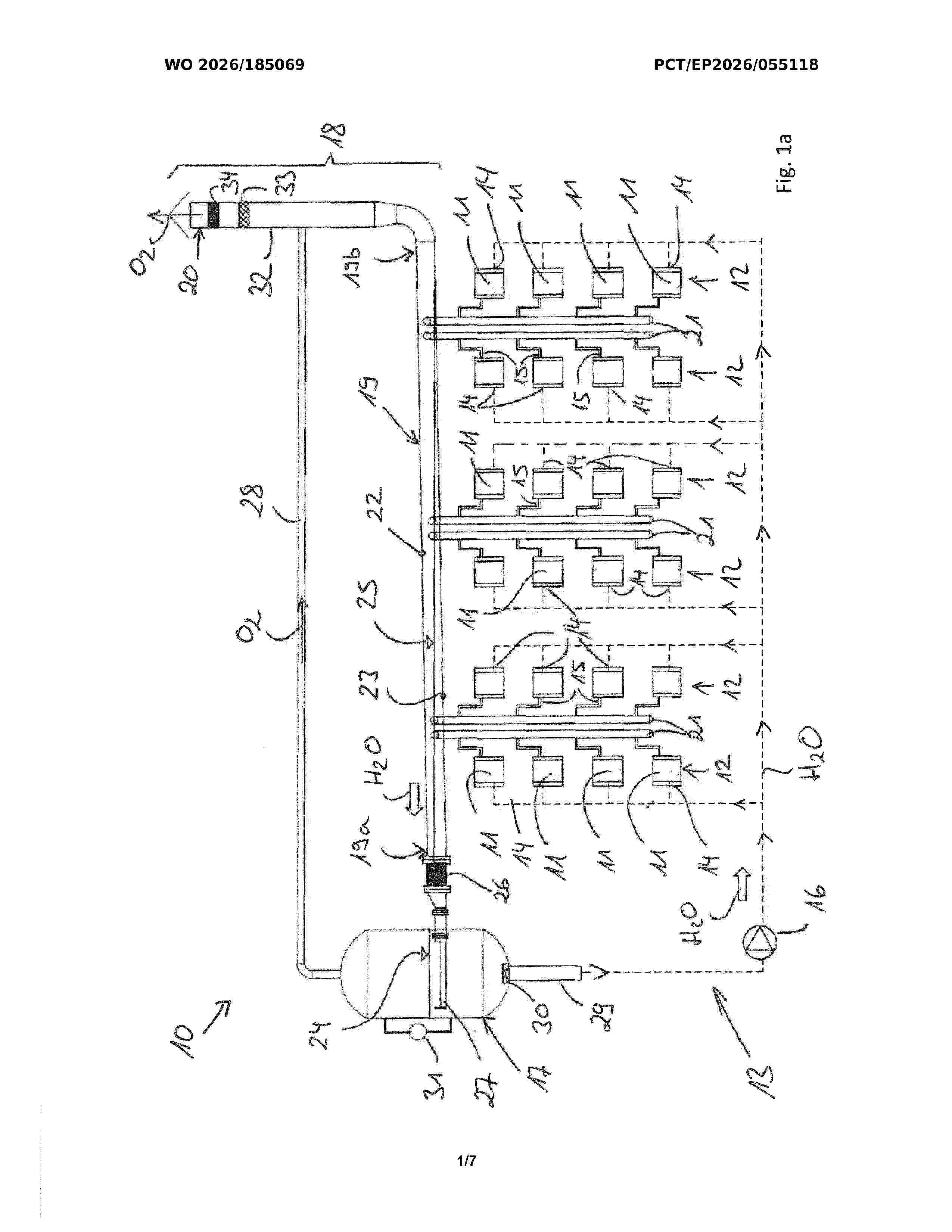
Resumen de: WO2026185069A1
The invention relates to a hydrogen-production plant (10), comprising: a plurality of electrolysis devices (11) which are designed to generate hydrogen from water with the aid of electrical current, wherein oxygen is produced during the generation of the hydrogen; a water circuit (13) which is designed to supply water to the electrolysis devices and to remove water and oxygen from the same, wherein the water circuit (13) has a water storage container (17) from which water can be supplied to the electrolysis devices, wherein the water circuit (13) has a pump (16) which is designed to convey the water from the water storage container (17) towards the electrolysis devices, wherein the water circuit (13) has an oxygen separator (18) which is designed to separate oxygen from the water discharged by the electrolysis devices upstream of the water storage container (17). The oxygen separator (18) has at least one first, horizontally extending separation tube (19) to which water and oxygen can be supplied from the electrolysis devices, wherein from a first end (19a) of the respective first, horizontally extending separation tube (19), water can be conducted towards the water storage container (17), and wherein, from a second end (19b) of the respective first, horizontally extending separating tube (19), oxygen can be conducted towards an oxygen outlet (20).
Resumen de: WO2026185353A1
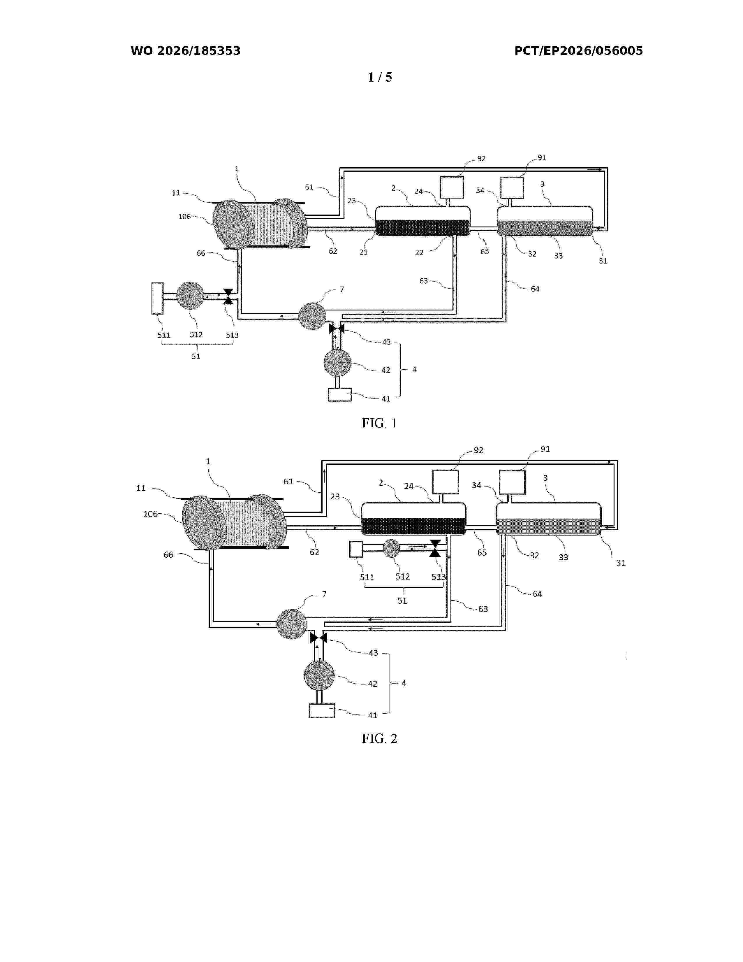
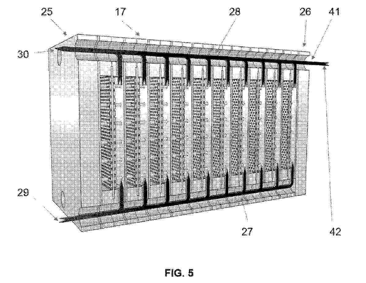
The present invention discloses an electrolysis device. The electrolysis device according to the present invention incorporates a reactor, a hydrogen gas-liquid separator, an oxygen gas-liquid separator and a cleaning component, the cleaning component is connected to the reactor, the hydrogen gas-liquid separator and/or the oxygen gas-liquid separator, and is configured to store a cleaning agent for pickling, and is configured to provide the cleaning agent to the electrolysis device during pickling, such that a pickling operation may be performed efficiently, to improve production efficiency.
Resumen de: AU2025262338A1
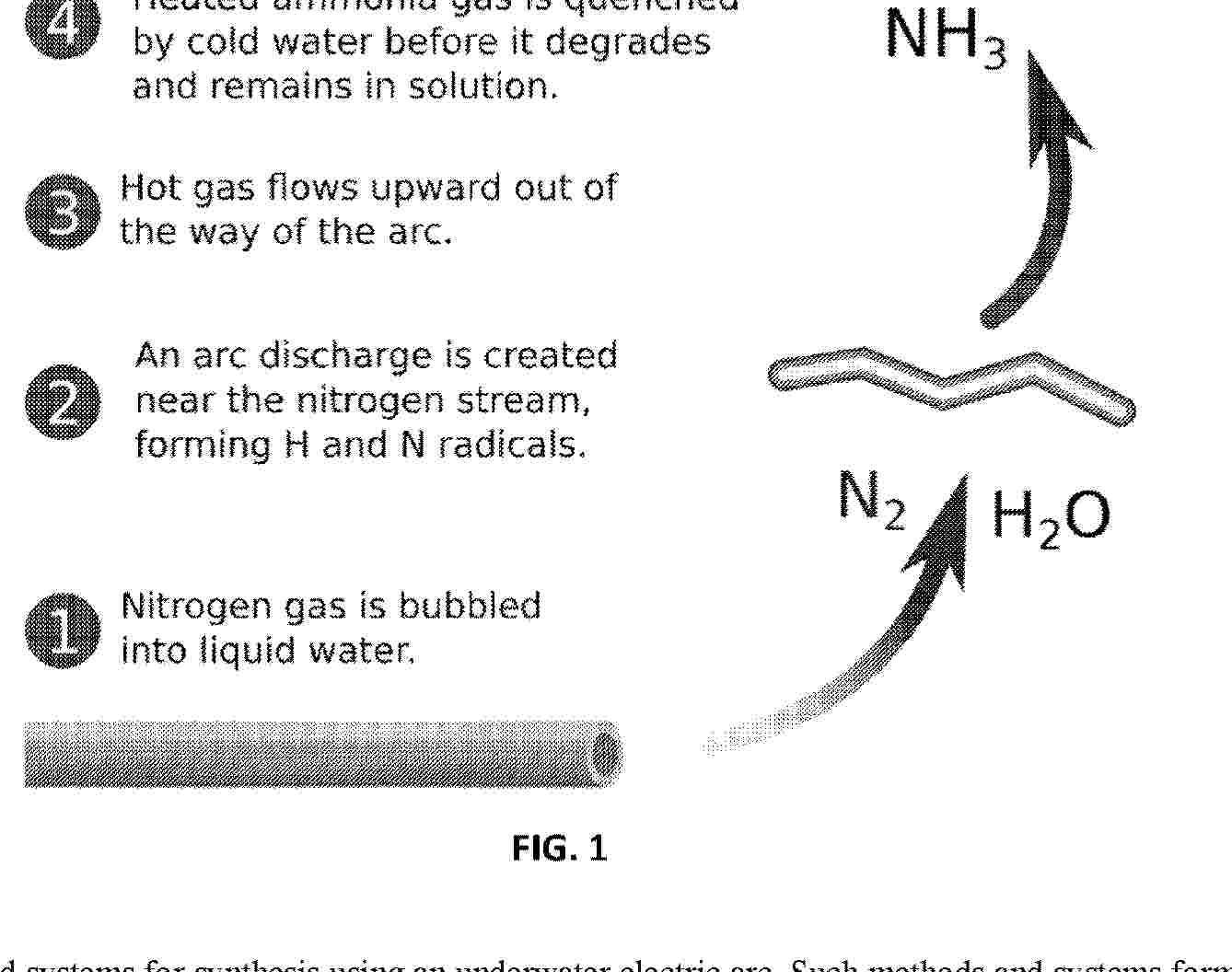
Methods and systems for synthesis using an underwater electric arc. Such methods and systems form an electrical arc between an anode and a cathode positioned under water or within an aqueous mist and introduce an added material into the vicinity of the electrical arc. The formation of the electrical arc in the vicinity of the added material facilitates synthesis of chemical products from the added material. Such synthesized chemical products include ammonia, hydrogen, cyanide, and hydrogen cyanide.
Resumen de: WO2025056228A1
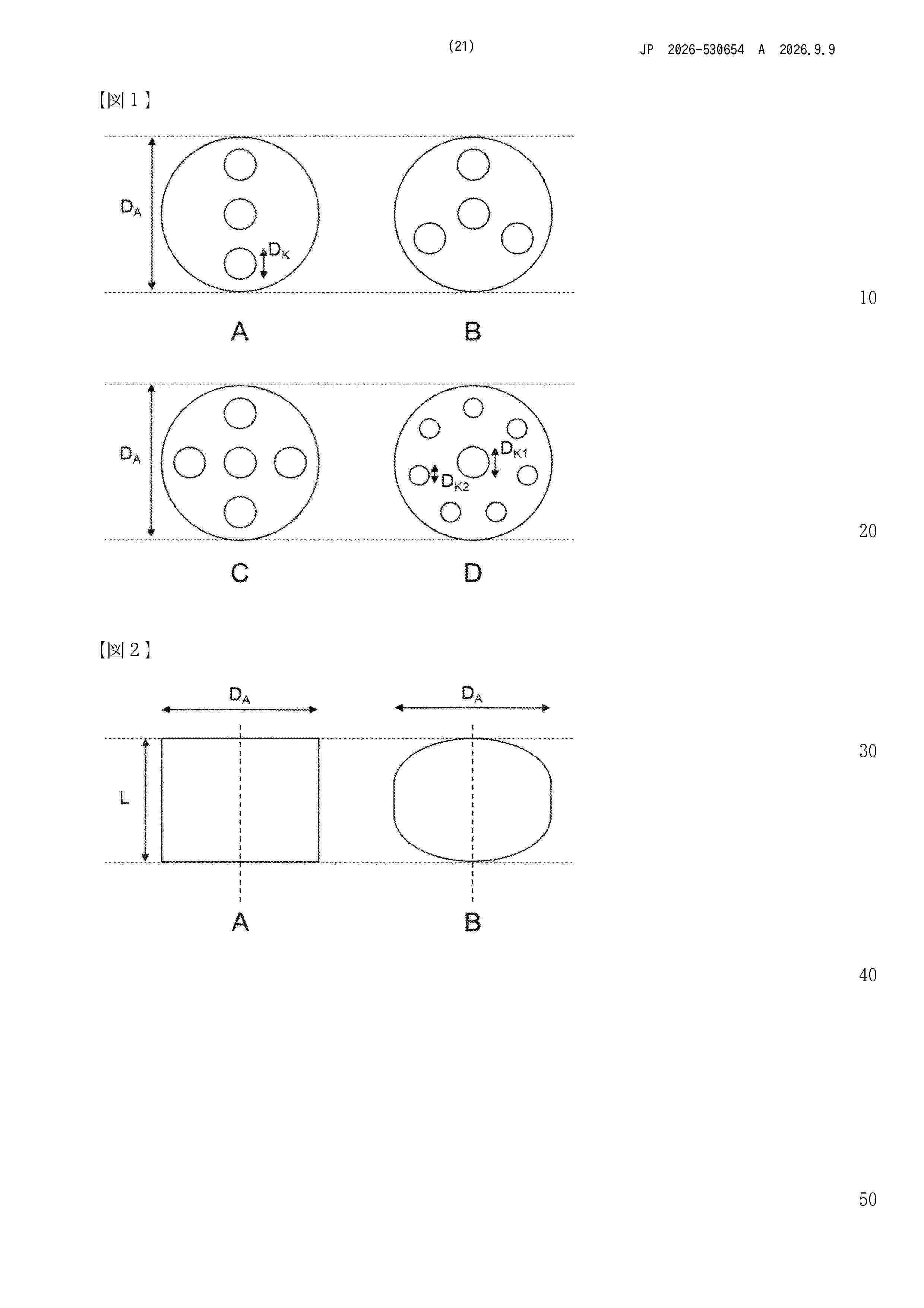
The present invention relates to a process for producing hydrogen from an ammonia-containing gas with a supported catalyst in the form of a ruthenium-endowed support body, and to the use of such a ruthenium-containing supported catalyst in a process for producing hydrogen. The process comprises the providing of a supported catalyst in the form of a ruthenium-endowed support body, wherein the support body comprises a refractory oxide as support material, is cylindrical and has at least three mutually spaced-apart channels that extend fully through the support body, where one of the channels extends along a central longitudinal axis.
Resumen de: TW202503118A
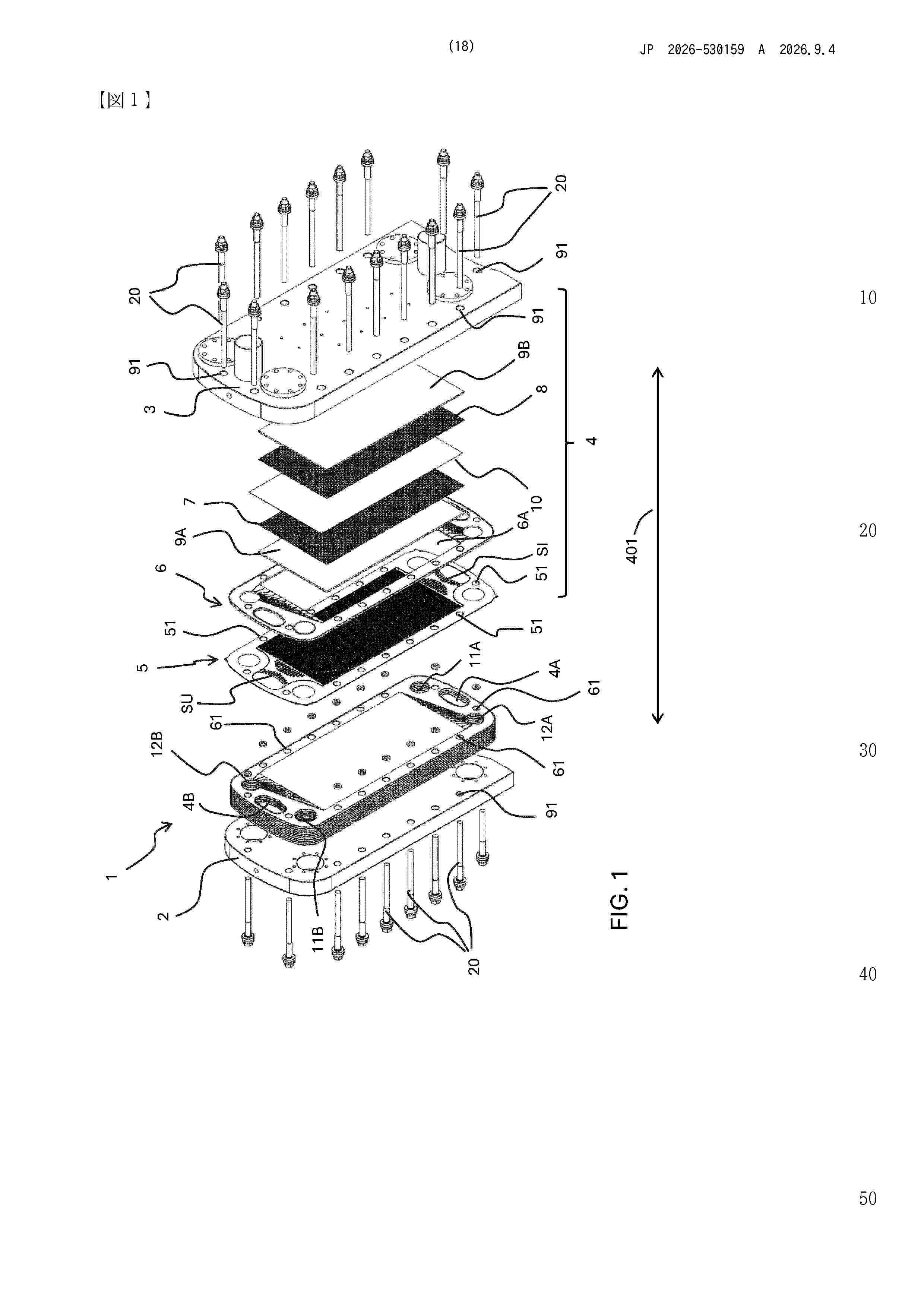
The present invention refers to an electrolyzer (1) for the production of hydrogen from an alkaline electrolyte. The electrolyzer (1) comprises a first header (11) and a second header (12) between which a plurality of elementary cells (20) and a plurality of bipolar plates (5, 5', 5") are stacked. Each bipolar plate (5) separates two adjacent elementary cells. According to the invention, each of said bipolar plates (5, 5',5") comprises two plate-form components (5A, 5B) coupled together and configured so as to define one or more inner cavities (66) for the circulation of a cooling fluid. Furthermore, each bipolar plate (5, 5', 5") comprises an inlet section (SI) and an outlet section (SV) respectively for the inlet and outlet of said cooling fluid in said one or more inner cavities (66).
Resumen de: WO2025040149A1
Disclosed in the present invention is a composite membrane for a water electrolysis cell. The composite membrane contains non-woven fabric and polymer resin, the polymer resin being present in one or two sides of the non-woven fabric and partially or completely permeating into the non-woven fabric structure, the non-woven fabric accounting for 20-95% of the weight of the composite membrane, the thickness of the non-woven fabric being 0.20-2.00 mm, the gram weight thereof being 100-400 g/m2, and the density thereof being 0.20-0.50 g/cm3. The composite membrane for a water electrolysis cell of the present invention has the characteristics of high air impermeability, low resistance and high service durability in alkali liquor environments.
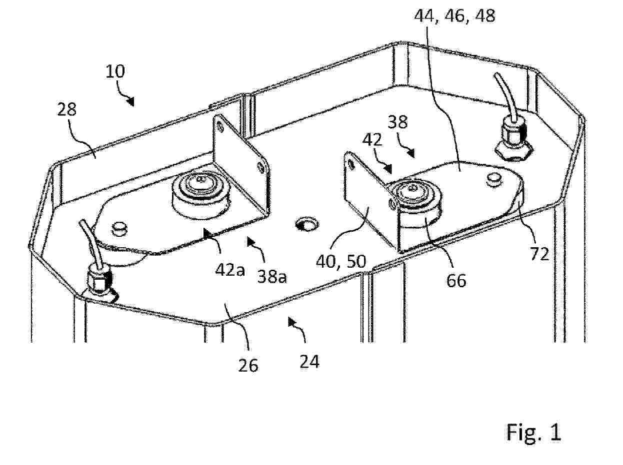
Resumen de: WO2025093132A1
The invention relates to an electrochemical cell assembly (10), comprising a base plate, an end plate (26), a stack (12) comprising a plurality of cell units (14) stacked upon one another, said stack (12) being arranged between said base plate and said end plate, and an electrically conductive power transmission device (38) comprising a connector (40) that is located on a side of the end plate that is facing away from the stack, the power transmission device spanning the end plate and being electrically connected to the stack, wherein the power transmission device is attached to the end plate by a fastening device (42) at a portion of the power transmission device that is located between an electrical connection to the stack and the connector.
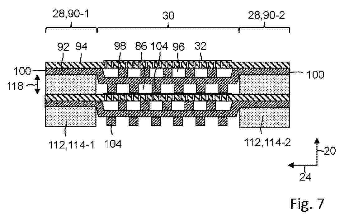
Resumen de: WO2025093133A1
The invention relates to an electrochemical cell assembly, comprising a stack of cell units, wherein each cell unit has a periphery and a central portion surrounded by the periphery, the periphery has a first flange portion (90-1) and an opposite second flange portion (90-2), the flange portions of adjacent cell units overlie one another and are separated by a gap (88-1, 88-2), wherein between two adjacent cell units, there is provided a fluid flow path comprising an inner flow path between the central portions of adjacent cell units and an outer flow through said gaps, and a flow restriction device (112) comprising at least one flow restriction member (114-1, 114-2), said flow restriction device being configured to reduce or prevent fluid flow along the outer flow path.
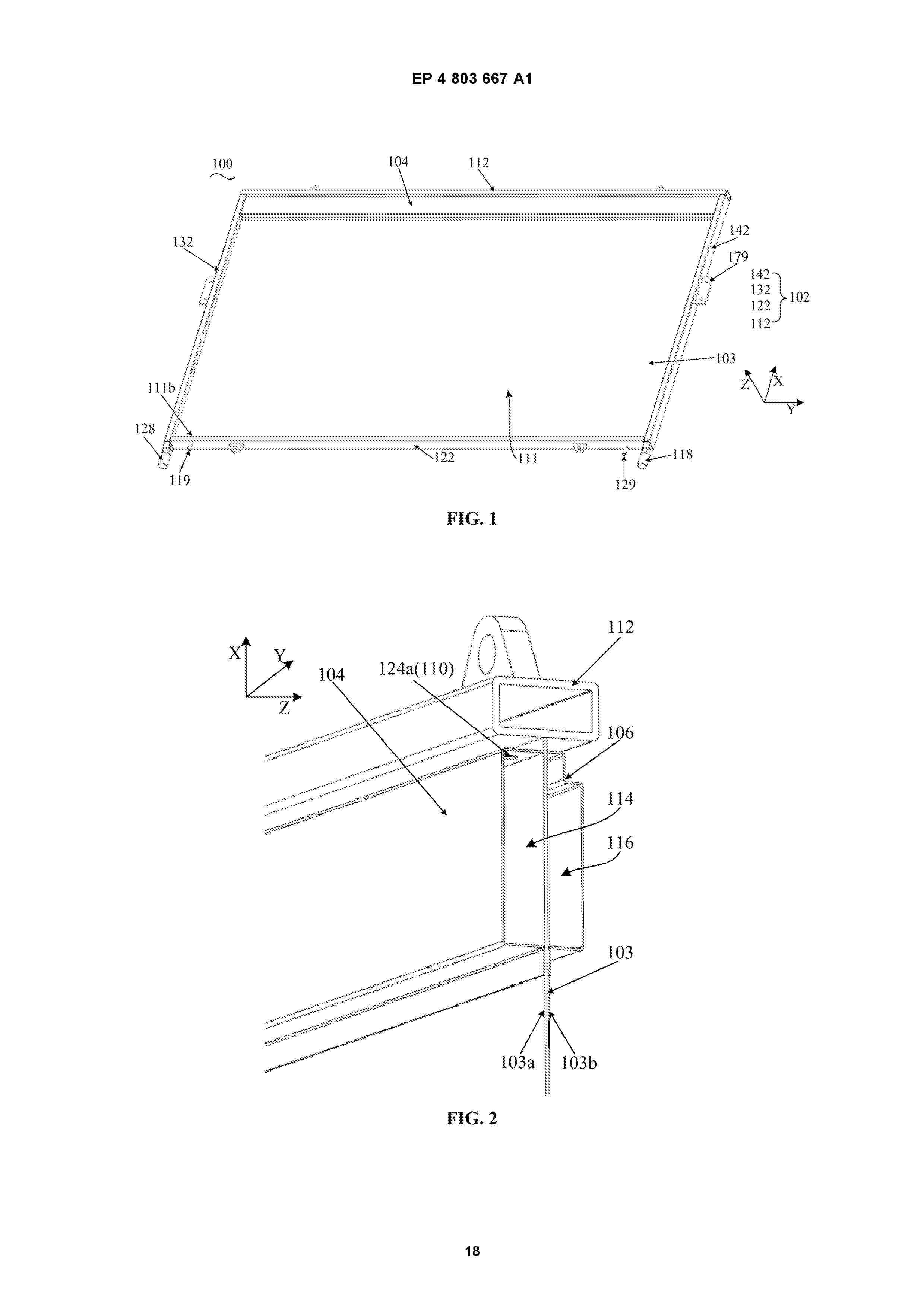
Resumen de: EP4803667A1
An electrolyzer, a method for manufacturing the electrolyzer, and an electrolyzer module are provided, relating to the field of electrolyzers. The electrolyzer includes: a frame defining an inner cavity and including a top frame, a bottom frame, a first frame, and a second frame; a bipolar plate connected to the frame and dividing the inner cavity into an anode chamber and a cathode chamber; a first collection frame, located within the anode chamber and fixed to an end of the bipolar plate near the top frame, and defining a first cavity together with the bipolar plate; an anode mesh, located on a side of the first collection frame away from the bipolar plate; a second collection frame, located within the cathode chamber and fixed to an end of the bipolar plate near the top frame, and defining a second cavity together with the bipolar plate; a cathode mesh, located on a side of the second collection frame away from the bipolar plate. The first frame and the second frame each have a hollow chamber. One of the first frame and the second frame has a first discharge port formed on an inner wall facing the anode chamber, and the other of the first frame and the second frame has a second discharge port formed on an inner wall facing the cathode chamber, the first discharge port being in communication with the first cavity, and the second discharge port being in communication with the second cavity. This is at least advantageous in improving electrolysis efficiency of the electrolyze
Resumen de: EP4803660A1
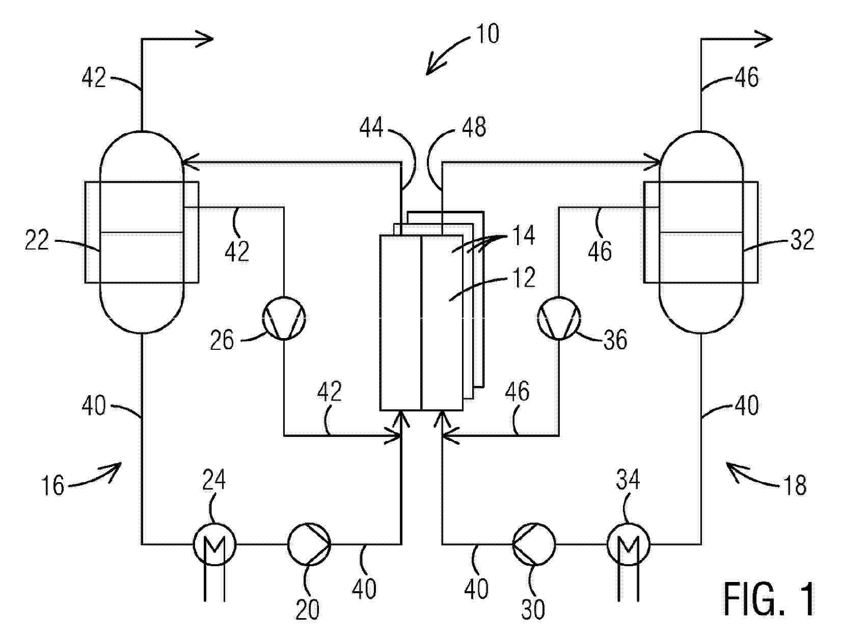
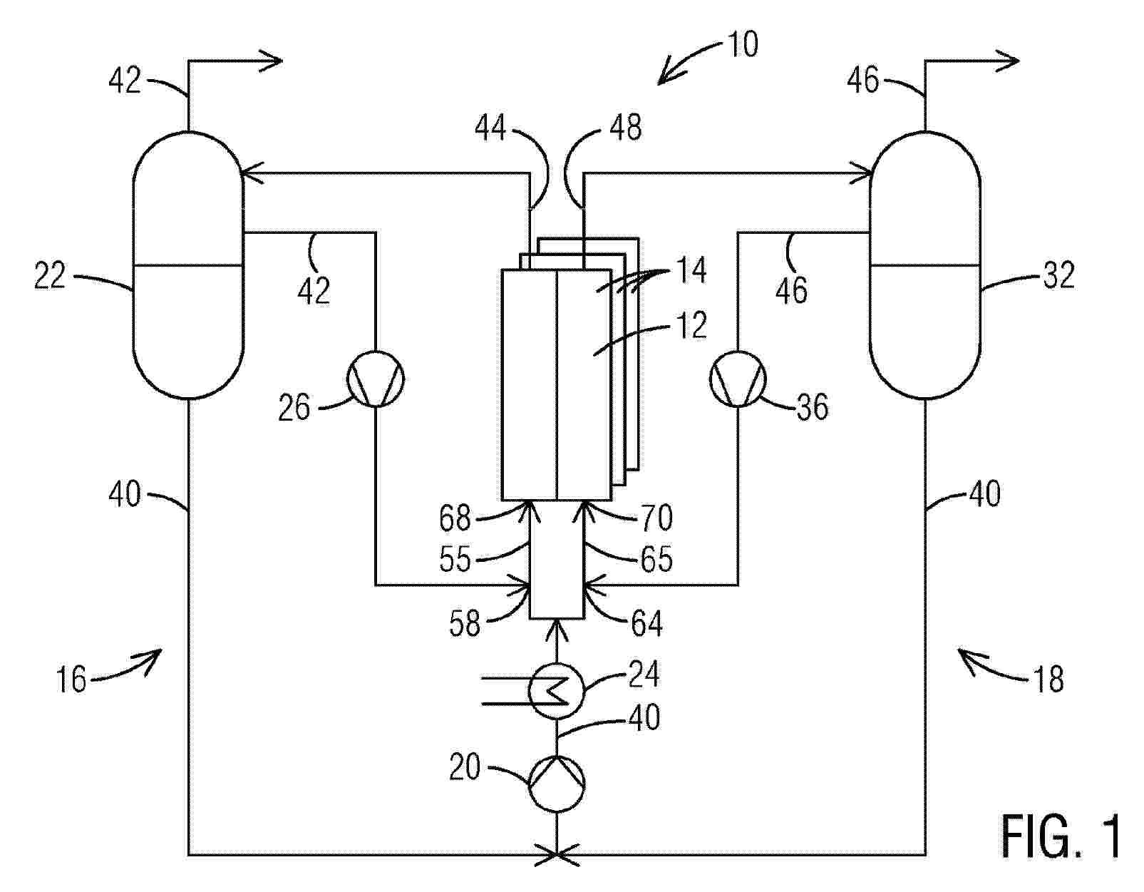
A gas inlet conduit (58) is constructed and arranged to feed a gas (42) into an active area (50) of an electrolysis cell (12) within a stack (14) in sufficient quantity to function as an electrical insulator and reduce an electric current at an entry (52) of the active area (50) and thereby more closely balance the current at the entry (52) of the active area (50) with the current at an exit (54) of the active area (50). Also, an electrolysis-separated stack configuration (10) is provided having a plurality of electrolytic cells (12) forming an electrolysis stack (14), a hydrogen-side pump (20) in fluid communication with a hydrogen-side phase separator (22) in fluid communication with a hydrogen-side heat exchanger (24) in fluid communication with a hydrogen-side recycle blower (26); where the electrolysis stack (14) is shared with an oxygen-side pump (30) in fluid communication with an oxygen-side phase separator (32) in fluid communication with an oxygen-side heat exchanger (34) in fluid communication with the oxygen-side recycle blower (36); wherein hydrogen (42) is generated.
Resumen de: EP4803822A1
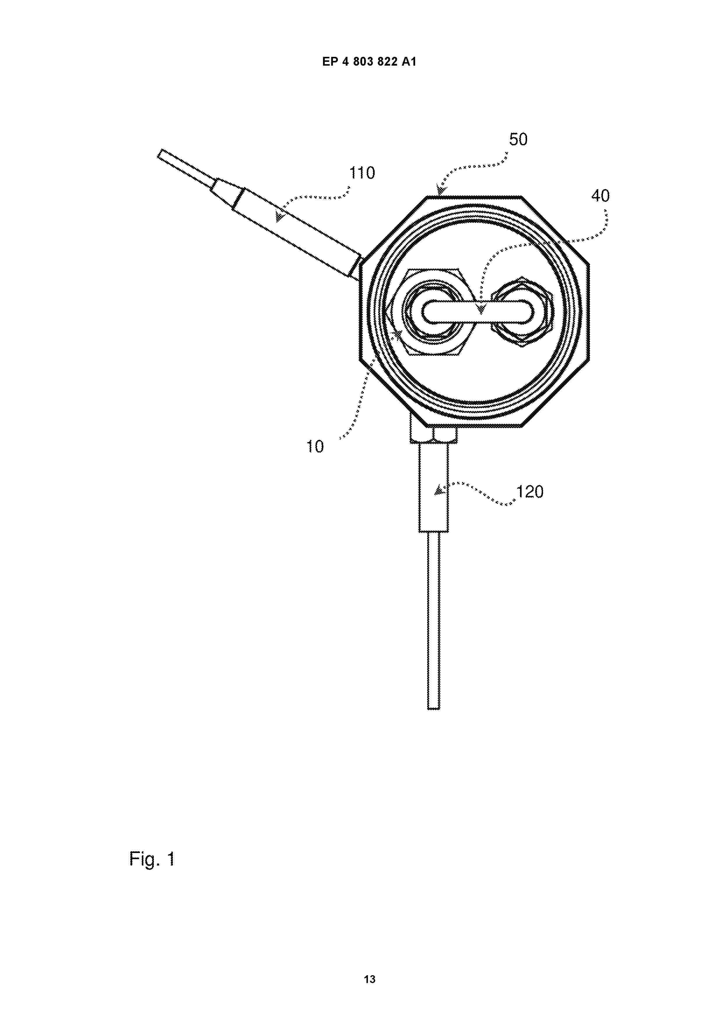
0001 Die vorliegende Erfindung betrifft eine Vorrichtung zur Wärmeerzeugung sowie ein dazugehöriges Verfahren und ein Computerprogramm, wobei durch eine Einlassöffnung ein Wasserstoff (H<2>)-Gasgemisch in mindestens einen Reaktionsraum geleitet wird, wobei der Reaktionsraum in Verbindung mit einem Impulszünder steht, welcher eine Initialzündung des Gasgemisches im Reaktionsraumes erzeugt, der dabei entstehende Wasserdampf wird über mindestens eine Auslassöffnung aus dem Reaktionsraum in ein Dampfrohr geführt, in dem der Wasserdampf kondensiert, wobei das Dampfrohr derart ausgebildet ist, dass es eine Kurve bildet und parallel zum Reaktionsraum zurückgeführt wird, wodurch das darin gebildete Wasser zur Aufrechterhaltung der Reaktion im Reaktionsraum und/oder zur Wiederverwendung in einem Elektrolyseprozess verwendet werden kann.
Resumen de: EP4803666A1
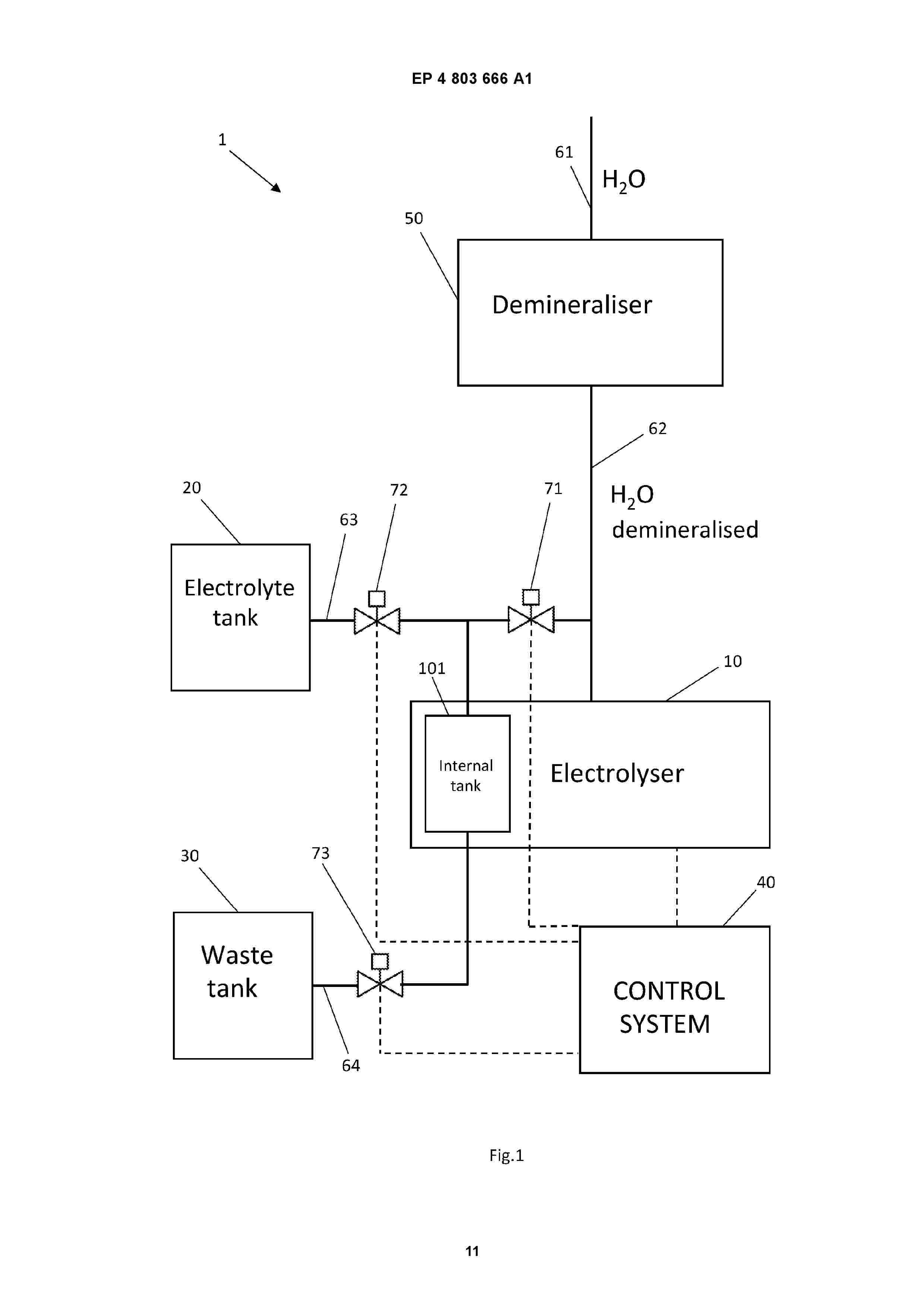
The present invention relates to a hydrogen production system (1). The system (1) comprises an electrolyser (10), equipped with an internal tank (101), adapted to produce hydrogen from the electrolysis of water, and a water distribution pipe (62) adapted to connect the internal tank (101) of the electrolyser (10) to a water source (50).Advantageously, the system also comprises an electrolyte tank (20) adapted to contain a quantity of electrolyte equal to or greater than the quantity of electrolyte contained by the internal tank (101) of the electrolyser (10), and a waste tank (30) adapted to contain a quantity of fluid greater than the quantity of electrolyte contained by the internal tank (101) of the electrolyser (10). Furthermore, the system comprises an electrolyte distribution pipe (63) adapted to connect the internal tank (101) of the electrolyser (10) to the electrolyte tank (20), a drain pipe (64) adapted to connect the internal tank (101) of the electrolyser (10) to the waste tank (30), and a water control valve (71) adapted to regulate the flow of fluid in the water distribution pipe (62), an electrolyte control valve (72) adapted to regulate the flow of fluid in the electrolyte distribution pipe (63), and a control valve (73) adapted to regulate the flow of fluid in the drain pipe (64). Finally, the system comprises a control unit (40) connected to the electrolyser (10) and the valves (71-73) to control its operation. In particular, the electrolyser (10) measures a
Resumen de: EP4804378A1
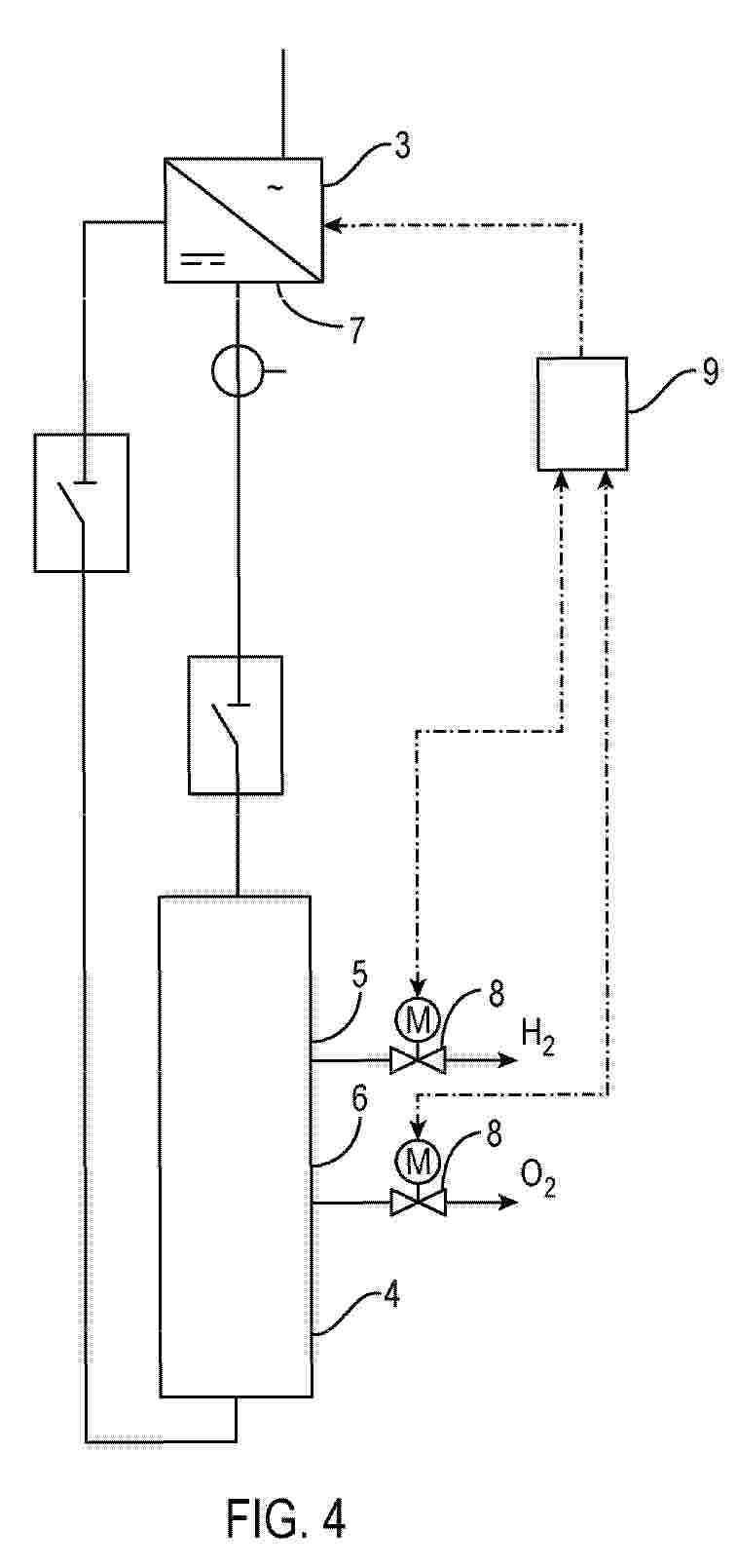
0001 The invention is about a method for controlling an electrolysis system (1) comprising a transformer unit (2), rectifier units (3) operating in parallel, and electrolysis module rows (4) with hydrogen and oxygen sides (5, 6) connected at DC sides (7) of the rectifier units (3), the method comprising: - detecting a Fault Ride Through event; and - adjusting the ramp-up rate of a DC current considering a current position of control valves (8) on the hydrogen and oxygen sides (5, 6).
Resumen de: WO2025093091A1
An alkaline electrolyzer comprising a stack (17) of electrolytic cells (1) for producing hydrogen gas (8). Each of the cathode compartments (5) comprises a cathode gas outlet (23A) into a cathode electrolyte return conduit (28), the downstream end (41) of which is connected to a hydrogen purifier (33) configured for providing purified hydrogen gas by removing oxygen from the gas received from the cathode electrolyte return conduit (28). A cathode gas recirculation system (38) connects a downstream end of the hydrogen purifier (32, 33) to an upstream end (40) of the cathode electrolyte return conduit (28) for supplying purified hydrogen gas to the cathode electrolyte return conduit (28). Each of the anode compartments (6) comprises an anode gas outlet (23B) into an anode electrolyte return conduit (28), the downstream end (41) of which is connected to an oxygen purifier (33) which removes hydrogen from the gas coming from the anode electrolyte return conduit (28). An anode gas recirculation system (38) connects a downstream end (41) of the oxygen purifier (33) to an upstream end (40) of the anode electrolyte return conduit (28) for supplying purified oxygen gas to the anode electrolyte return conduit (28). Hereby the electrolyzer can be operated at part load, for example below 10% of the nominal load.
Resumen de: EP4803659A1
0001 A gas conduit (58) is constructed and arranged to feed a gas (42) into an active area (50) of an electrolysis cell (12) within a stack (14) in sufficient quantity to function as an electrical insulator and reduce an electric current at an entry (52) of the active area (50) and thereby more closely balance the current at the entry (52) of the active area (50) with the current at an exit (54) of the active area (50). Also, an electrolysis-mixed stack configuration (10) is provided having a plurality of electrolytic cells (12) forming an electrolysis stack (14), a pump (20) in fluid communication with a hydrogen-side phase separator (22) in fluid communication with a heat exchanger (24) in fluid communication with a hydrogen-side recycle blower (26); where the electrolysis stack (14) is shared with an oxygen-side (16) having a pump (20) in fluid communication with an oxygen-side phase separator (32) in fluid communication with the heat exchanger (24) in fluid communication with the oxygen-side recycle blower (36); wherein hydrogen (42) is generated.
Resumen de: WO2024064495A2
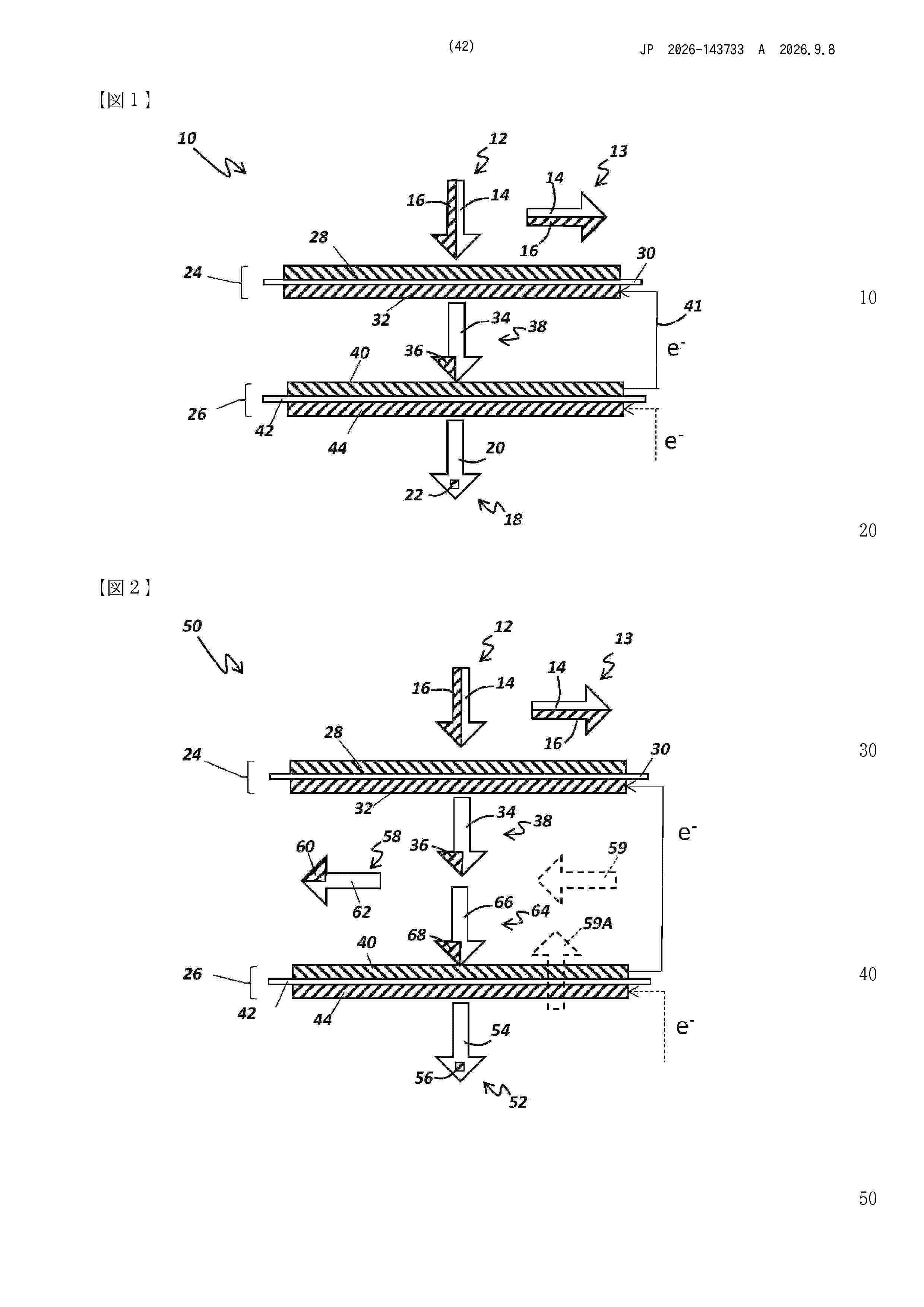
Hydrogen gas purifier electrochemical cells (10, 50, 150), systems (200) for purifying hydrogen gas, and methods for purifying hydrogen gas are provided. The cells, systems, and methods employ double membrane electrode (DMEA) electrochemical cells (24, 26, 152) that enhance purification while avoiding the complexity and cost of conventional cells. The purity of the hydrogen gas produced by the cells, systems, and methods can be enhanced by removing at least some intermediate gas impurities from the cells. The purity of the hydrogen gas produced by the cells, systems, and methods can also be enhanced be introducing hydrogen gas to the cells to replenish any lost hydrogen. Water electrolyzing electrochemical cells (250) and methods of electrolyzing water to produce hydrogen gas are also disclosed.
Resumen de: CA3201278A1
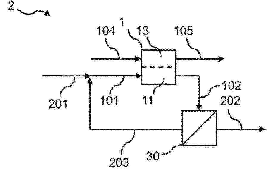
The present invention regards a method for converting carbon dioxide into carbon monoxide in high-temperature, dry, solid oxide electrolysis providing increased lifetime of SOECs and SOEC stacks by addressing the problem of coking, while simultaneously ensuring highest possible CO production from each cell or stack.
Resumen de: US20250059653A1
0000 Microorganisms and bioprocesses are provided that convert gaseous C1 containing substrates, such as syngas, producer gas, and renewable H<2 >combined with CO<2>, into nutritional and other useful bioproducts.
Resumen de: WO2025045641A1
The present invention refers to an electrolyser (1) for the production of hydrogen from an alkaline electrolyte. The electrolyser (1) comprises a first header (2) and a second header (3) between which a plurality of elementary cells (4) and a plurality of bipolar plates (5) are stacked. Each bipolar plate (5) separates two adjacent elementary cells. The electrolyser (1) further comprises a plurality of clamping elements (20) that mechanically connect said headers (2, 3). Each of the elementary cells (4) comprises a frame (6) defining a chamber (6A), having an anodic section and a cathodic section, in which an anodic electrode (7) and a cathodic electrode (8) are at least in part housed. Each of the elementary cells (4) further comprise a separator element (10) that separates the anodic section from the cathodic section. According to the invention, each of the frames (6) comprises first through holes (61) and each of the bipolar plates (5) comprises second through holes (51), wherein each of said first through holes (61) of one frame (6) is mutually aligned with a corresponding first through holes (61) of each of the another frames (6) and with one of said second through holes (51) of each bipolar plate (5), wherein each one of said clamping means (20) extends through said through holes (51, 61) mutually aligned.
Resumen de: US20260257990A1
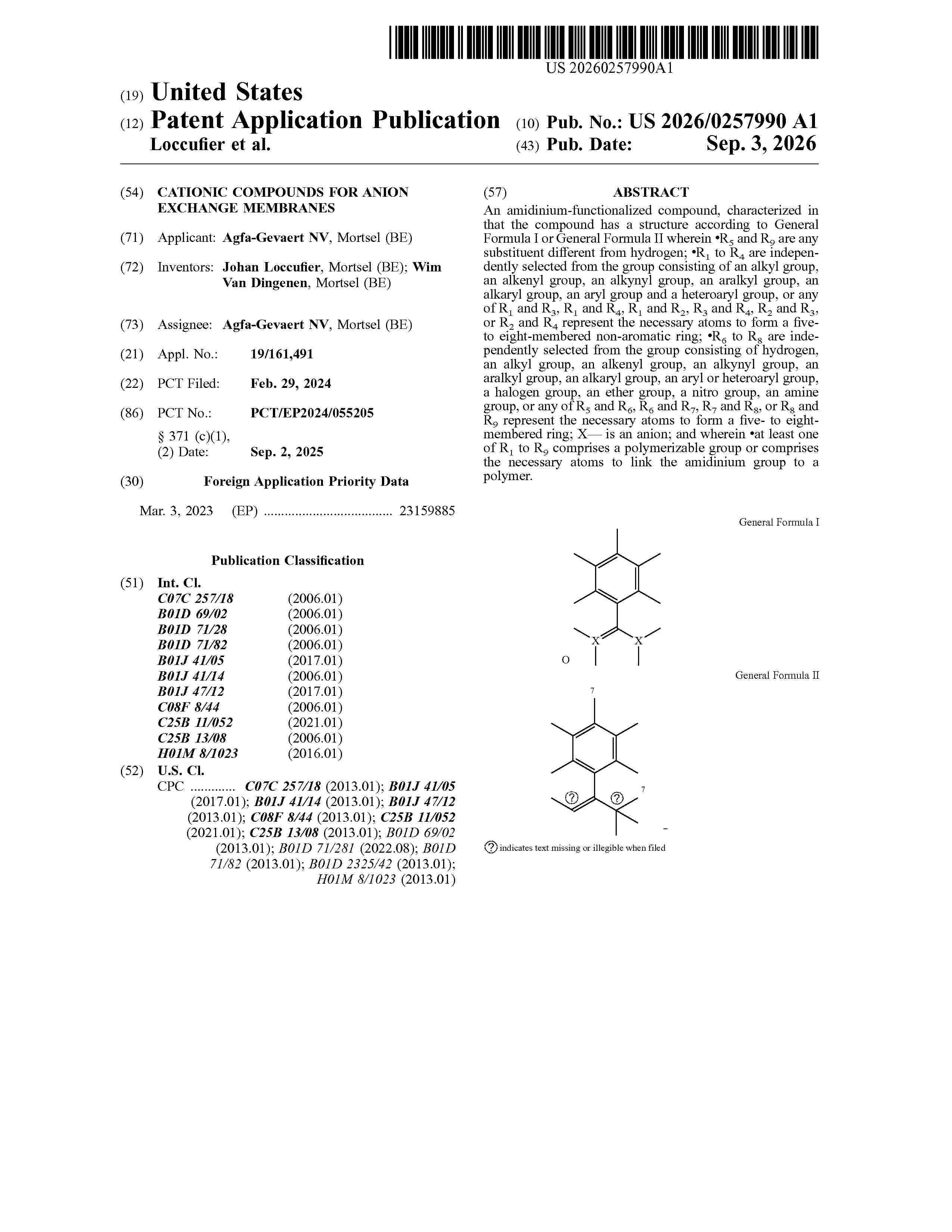
An amidinium-functionalized compound, characterized in that the compound has a structure according to General Formula I or General Formula II wherein ⋅R5 and R9 are any substituent different from hydrogen; ⋅R1 to R4 are independently selected from the group consisting of an alkyl group, an alkenyl group, an alkynyl group, an aralkyl group, an alkaryl group, an aryl group and a heteroaryl group, or any of R1 and R3, R1 and R4, R1 and R2, R3 and R4, R2 and R3, or R2 and R4 represent the necessary atoms to form a five- to eight-membered non-aromatic ring; ⋅R6 to R8 are independently selected from the group consisting of hydrogen, an alkyl group, an alkenyl group, an alkynyl group, an aralkyl group, an alkaryl group, an aryl or heteroaryl group, a halogen group, an ether group, a nitro group, an amine group, or any of R5 and R6, R6 and R7, R7 and R8, or R8 and R9 represent the necessary atoms to form a five- to eight-membered ring; X— is an anion; and wherein ⋅at least one of R1 to R9 comprises a polymerizable group or comprises the necessary atoms to link the amidinium group to a polymer.
Resumen de: WO2026182306A1
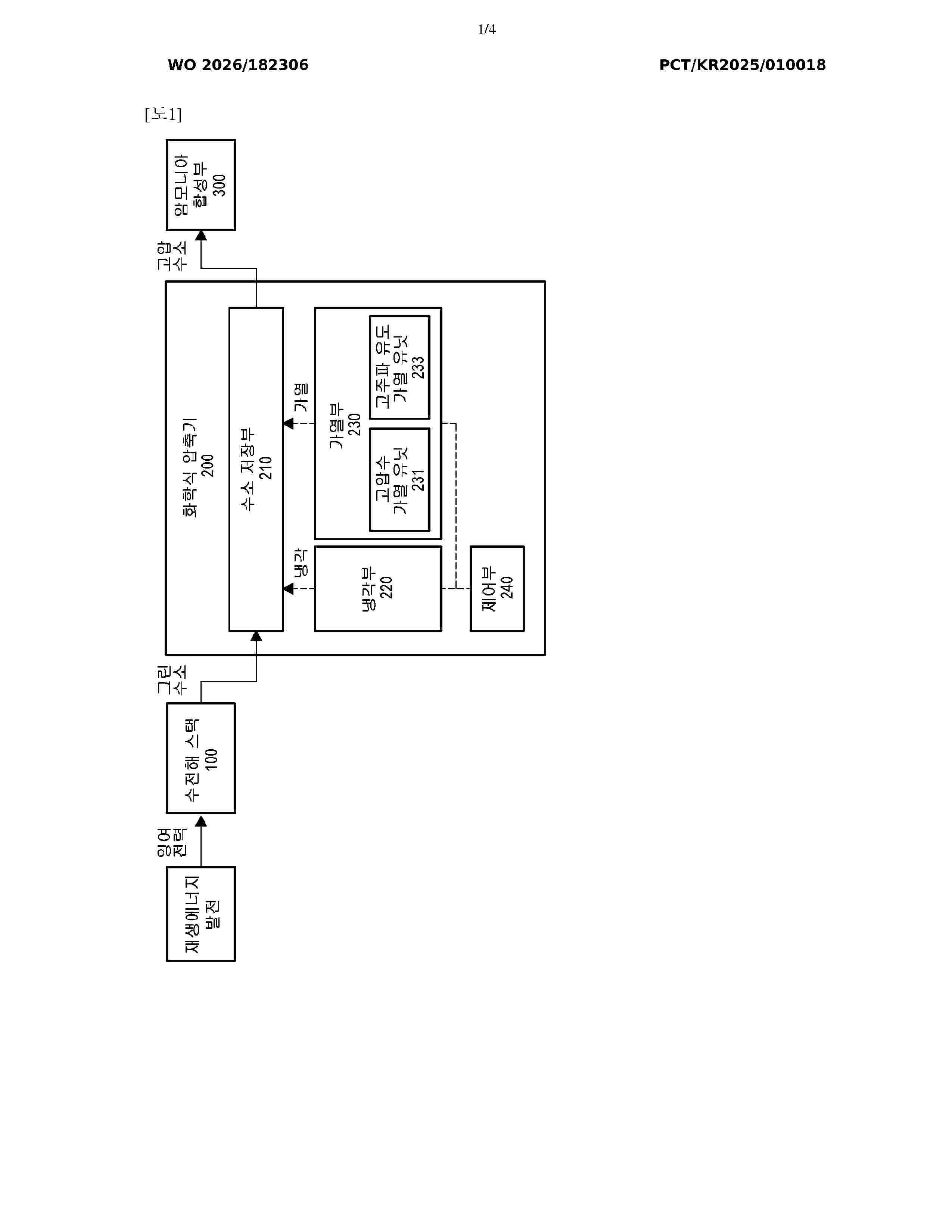
The present invention provides a system for synthesizing ammonia using a chemical compressor having a hydrogen storage alloy embedded therein, and a method for synthesizing ammonia using the ammonia synthesis system. The system for synthesizing ammonia comprises: a water electrolysis stack that generates hydrogen; a chemical compressor that stores and discharges hydrogen supplied from the water electrolysis stack; and an ammonia synthesis unit that receives hydrogen from the chemical compressor and synthesizes ammonia, wherein the chemical compressor includes: a hydrogen storage unit having the hydrogen storage alloy embedded therein; a cooling unit that cools the hydrogen storage unit; a heating unit that heats the hydrogen storage unit; and a control unit that controls operations of the cooling unit and the heating unit, wherein the heating unit includes a plurality of different heating sources independently controllable from one another, and the control unit controls the cooling unit to cool the hydrogen storage alloy of the hydrogen storage unit when hydrogen is stored in the hydrogen storage unit, and controls at least one of the plurality of heating sources of the heating unit to heat the hydrogen storage alloy when hydrogen is discharged from the hydrogen storage unit.
Nº publicación: US20260261119A1 03/09/2026
Solicitante:
SIEMENS ENERGY GLOBAL GMBH & CO KG [DE]
Siemens Energy Global GmbH & Co. KG
Resumen de: US20260261119A1
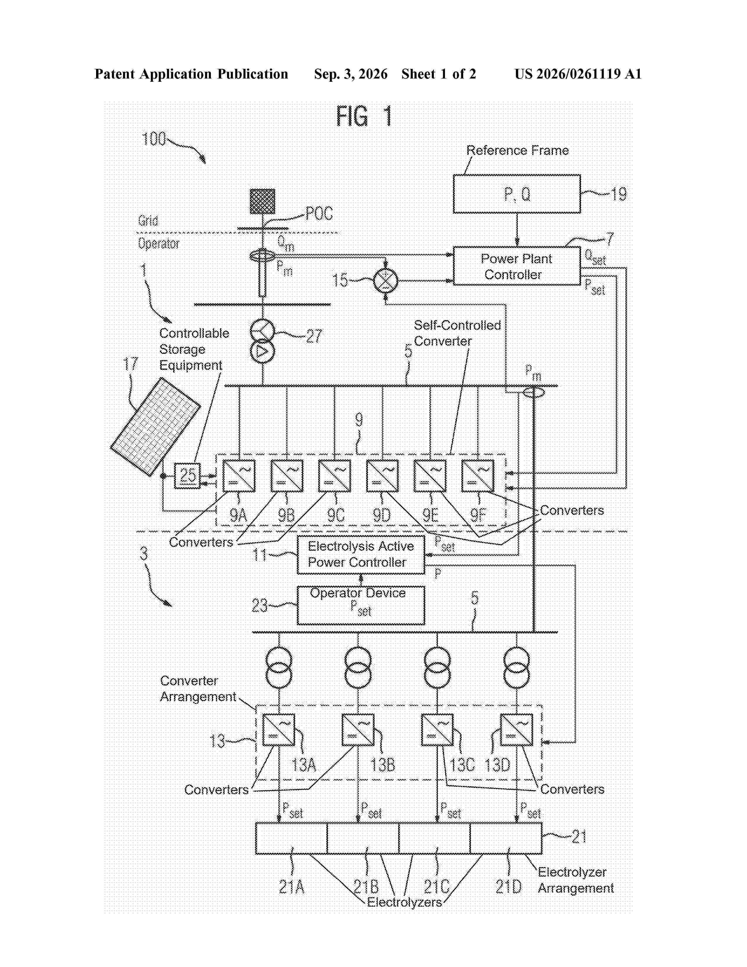
0000 An electrolysis system includes a renewable power generation plant, an electrolysis plant, a transformer station and an AC bus bar. The renewable power generation plant is connected to the public electricity grid at a point of connection via the AC bus bar and includes a power plant controller and a self-controlled converter that is connected to the AC bus bar. The electrolysis plant includes an electrolysis active power controller and a converter arrangement that is connected to the AC bus bar. The electrolysis active power controller is configured for controlling active power of the electrolysis plant at the AC bus bar and the power plant controller is configured for controlling reactive power at the point of connection. A method for operating an electrolysis system is also provided.
 BOPI
BOPI
 Sede Electrónica