Si deseas distinguir tus productos, servicios o ambos de los de otra empresa, es posible que necesites una marca o nombre comercial. Descubre qué son, en qué consiste su procedimiento de registro y qué implica.

Información sobre los plazos de presentación de solicitudes de transformación de marcas de la Unión Europea en marca nacional española. Más información


Si tienes un nuevo dispositivo, producto o procedimiento que resuelva un problema técnico o tenga una ventaja práctica, existen distintas formas de protegerlo en España y en otros países. Descubre cómo hacerlo.

¿Tu innovación reside en la estética, la ornamentación o la apariencia de tu producto? Protégela mediante un diseño industrial. Descubre qué derechos confiere el registro y cómo realizar la tramitación.

Las indicaciones geográficas protegen el nombre de un producto originario de una zona geográfica, a la cual le debe una determinada calidad, reputación u otra característica. Descubre qué son, en qué consiste su procedimiento de registro y qué beneficios conceden.

Las patentes publicadas en todo el mundo son una valiosa fuente de información científica, técnica y comercial.

Si eres emprendedor/a o una empresa y quieres potenciar y mejorar la rentabilidad de tu negocio protegiendo de forma adecuada los activos intangibles de tu organización, en este espacio encontrarás lo necesario.


 1500
resultados
1500
resultados
 Última actualización
27/06/2026 [07:57:00]
Última actualización
27/06/2026 [07:57:00]


 Resultados 350 a 375 de 1500

Resumen de: EP4765386A1
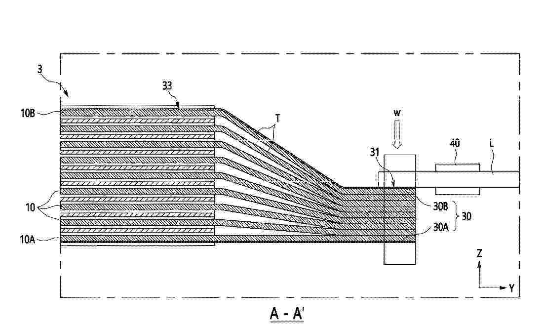
0001 A battery according to the present invention comprises: an electrode assembly including a plurality of stacked electrodes, a tab array formed by stacking a plurality of electrode tabs respectively extending from the plurality of electrodes, and a cover member covering the tab array; and an electrode lead electrically connected to the tab array. The cover member may include: an electrode cover part covering at least a partial surface of an electrode arranged at the outermost side among the plurality of stacked electrodes; and a tab cover part extending from the electrode cover part, arranged to face the tab array, and electrically connected to the electrode lead.

Resumen de: EP4765404A1
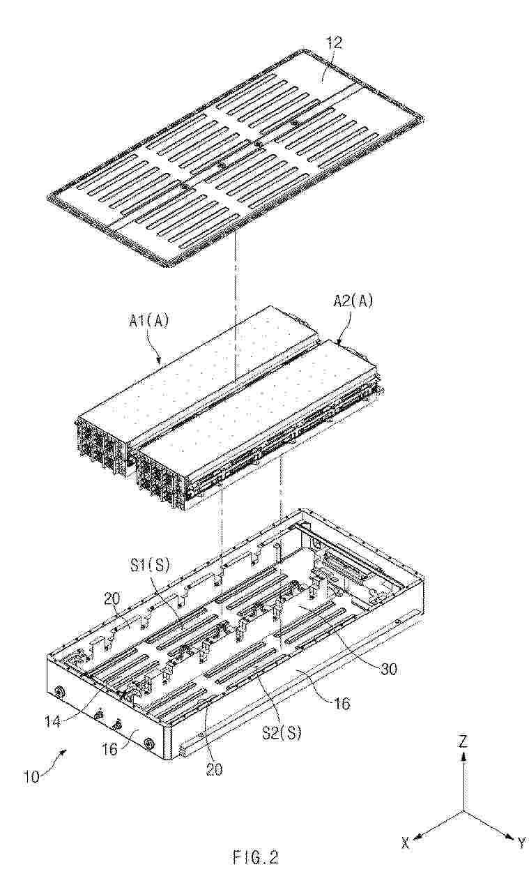
0001 The present disclosure relates to a battery pack, and the battery pack according to an aspect of the present disclosure includes a housing having an accommodation space, and a module assembly disposed in the accommodation space, wherein the module assembly includes a module array including a plurality of stacked battery modules, and a side frame including a plate portion disposed at a side of the module array and coupled to each of the plurality of battery modules and a support portion extended from the plate portion in an outward direction of the module array and supported by the housing.
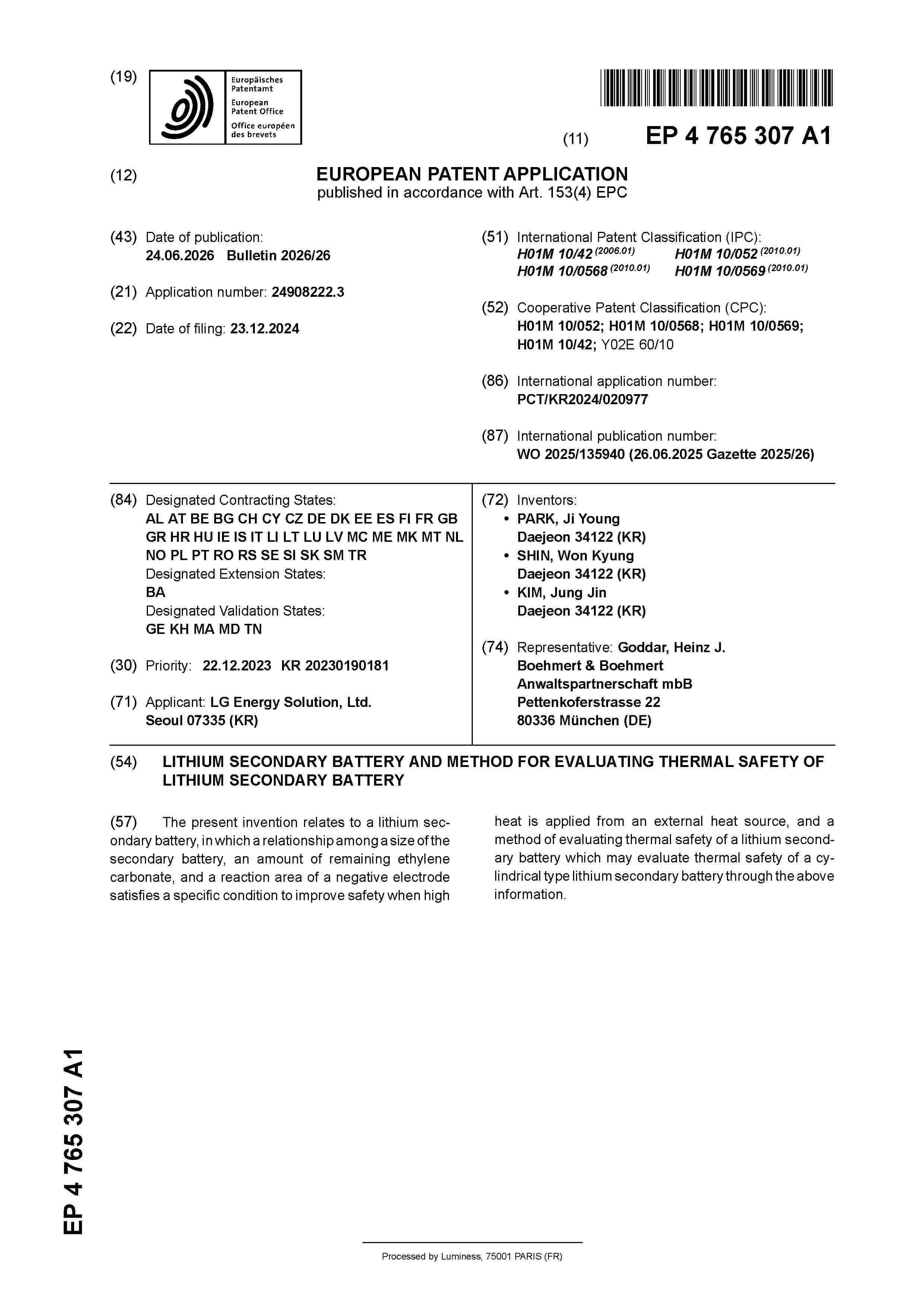
Resumen de: EP4765307A1
The present invention relates to a lithium secondary battery, in which a relationship among a size of the secondary battery, an amount of remaining ethylene carbonate, and a reaction area of a negative electrode satisfies a specific condition to improve safety when high heat is applied from an external heat source, and a method of evaluating thermal safety of a lithium secondary battery which may evaluate thermal safety of a cylindrical type lithium secondary battery through the above information.
Resumen de: EP4765322A1
A battery pack according to an embodiment disclosed herein may include a plurality of battery cells, a first material positioned between the plurality of battery cells, a piezoelectric sensor adjacent to the first material, a temperature sensor configured to detect temperatures of the plurality of battery cells, and a battery management apparatus configured to determine abnormality of the plurality of battery cells, abnormality of the piezoelectric sensor, and abnormality of the temperature sensor based on information received from the piezoelectric sensor and the temperatures of the plurality of battery cells.
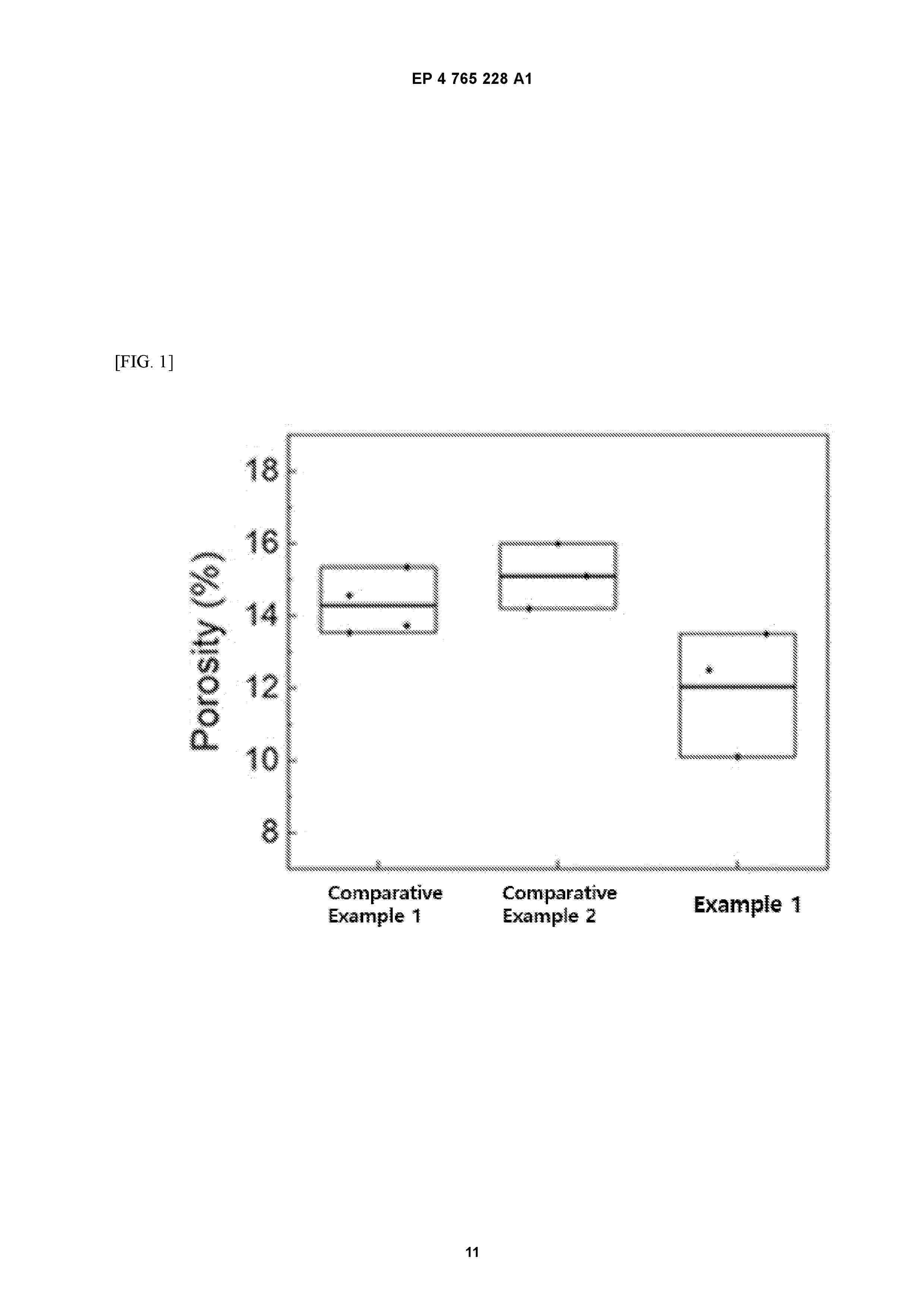
Resumen de: EP4765228A1
0001 The present disclosure relates to a positive electrode for an all-solid-state battery and an all-solid-state battery including the same.
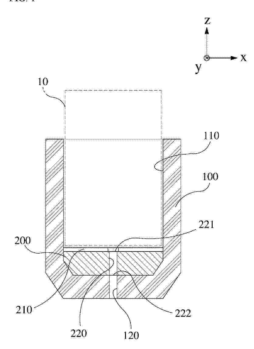
Resumen de: EP4765471A1
A jig for extracting an electrolyte is provided. The jig may extract an electrolyte from a sample to be analyzed provided as a cylindrical battery or a jelly-roll electrode assembly having a vertical direction as a longitudinal direction. The jig includes a body part having a cylindrical battery accommodation groove formed on the upper surface and a support part for supporting the lower end of the sample to be analyzed. An electrolyte discharge flow path is formed on the upper surface of the support part, and a first electrolyte discharge port penetrates the support part in the vertical direction. The body part also includes a second electrolyte discharge port for discharging an electrolyte. The inlet of the first electrolyte discharge port is connected to the electrolyte discharge flow path, and the outlet of the first electrolyte discharge port is connected to the second electrolyte discharge port.
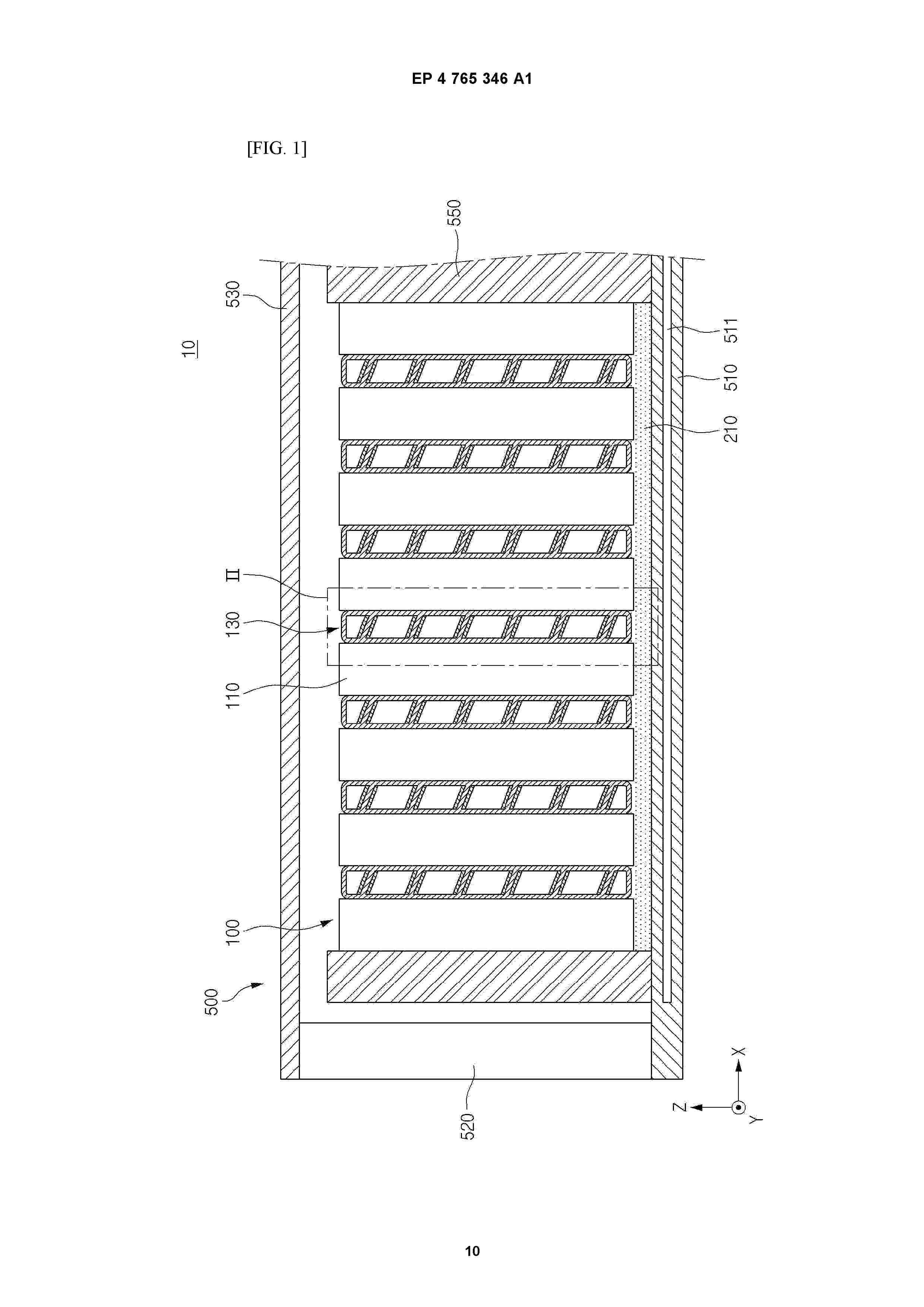
Resumen de: EP4765346A1
Disclosed herein relates to a battery device including: a first frame; a plurality of battery cells provided on the first frame; and a side pad disposed between the plurality of battery cells, wherein the side pad includes: an outer body in contact with the plurality of battery cells; an inner body provided within an internal space of the outer body; and a thermally expandable layer extending along the inner body and containing a thermally expandable material.
Resumen de: EP4765272A1
The present disclosure may provide an electrode assembly in which a positive electrode, a negative electrode, and a separator interposed therebetween are wound, wherein at least one of the positive electrode and the negative electrode includes an uncoated portion at a long side end, and a winding turn portion of the uncoated portion is provided at one end of the electrode assembly, wherein the winding turn portion includes a bending region including a plurality of uncoated portion layers configured to be bent by pressure to form a bent surface.
Resumen de: EP4765243A1
0001 A positive electrode active material according to the present invention is a positive electrode active material including a lithium nickel-based oxide particle in the form of a single particle which is composed of one single nodule, or a pseudo-single particle which is a composite of 30 or fewer nodules, and a coating layer formed on the surface of the lithium nickel-based oxide particle and including cobalt, wherein when the positive electrode active material is analyzed by X-ray photoelectron spectroscopy (XPS), XPS (Co/Ni), which is an atomic ratio of Co to Ni, is 0.15 or greater, when the positive electrode active material is analyzed by Auger electron spectroscopy (AES), AES (Co/Ni), which is a standard deviation of the atomic ratio of Co to Ni, is 0.80 or less, and the positive electrode active material has a content of residual Li<2>CO<3> of 0.50 wt% or less.
Resumen de: EP4765425A1
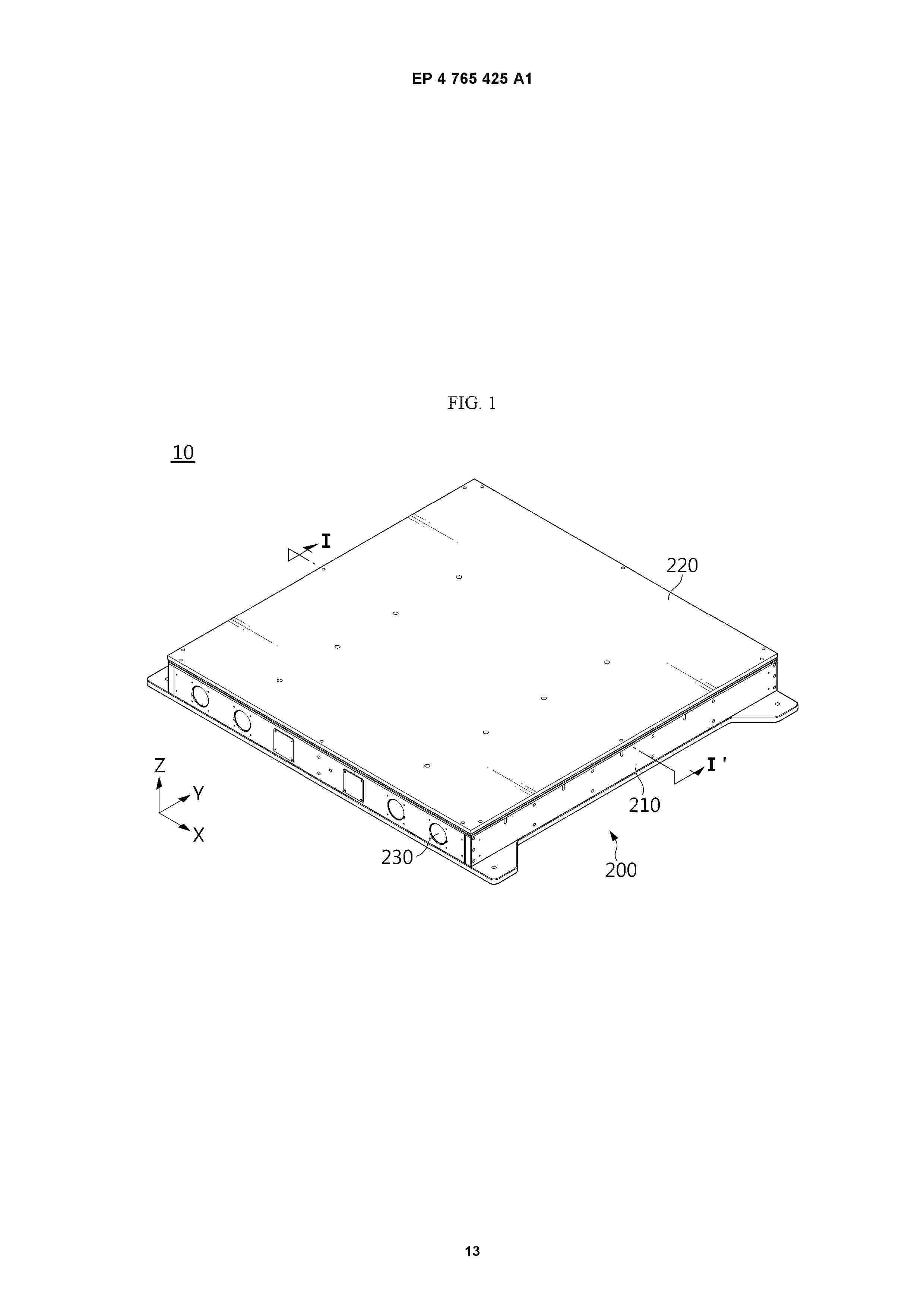
0001 The present disclosure relates to a battery pack mounted to a bottom of a chassis, which includes: a plurality of battery cells; a pack case configured to store the plurality of battery cells and having an upper side capable of being coupled to the chassis; and a fixing member interposed between the pack case and the chassis and configured to suppress deformation of the pack case.
Resumen de: EP4763373A1
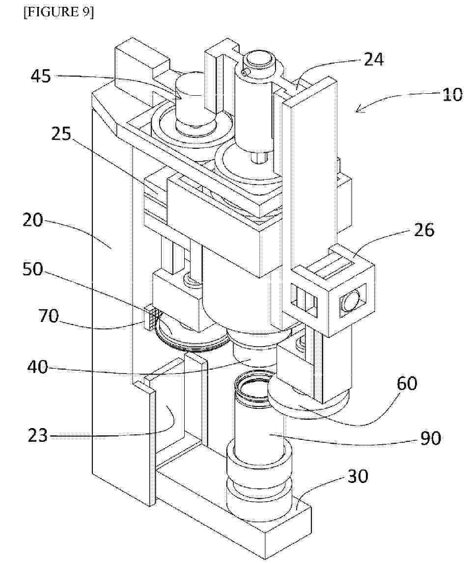
Provided is an apparatus capable of monitoring the abrasiveness of a forming tool for applying pressure to a battery can in the radial direction of the battery can along the circumferential direction thereof while rotating the battery can, to perform plastic working of the battery can in the radial direction thereof. The apparatus comprises: a can table installed to be rotatable about the central axis thereof; a process tool which is installed to be rotatable about a predetermined rotational center, is installed to be movable in a direction in which the process tool approaches or moves away from a can installed on the can table, and has a processing surface provided around the rotational center; a pressure sensor pressurized by the processing surface and measuring a pressure distribution; and a monitoring unit for calculating information related to a profile of the processing surface from the pressure distribution.
Resumen de: EP4763599A1
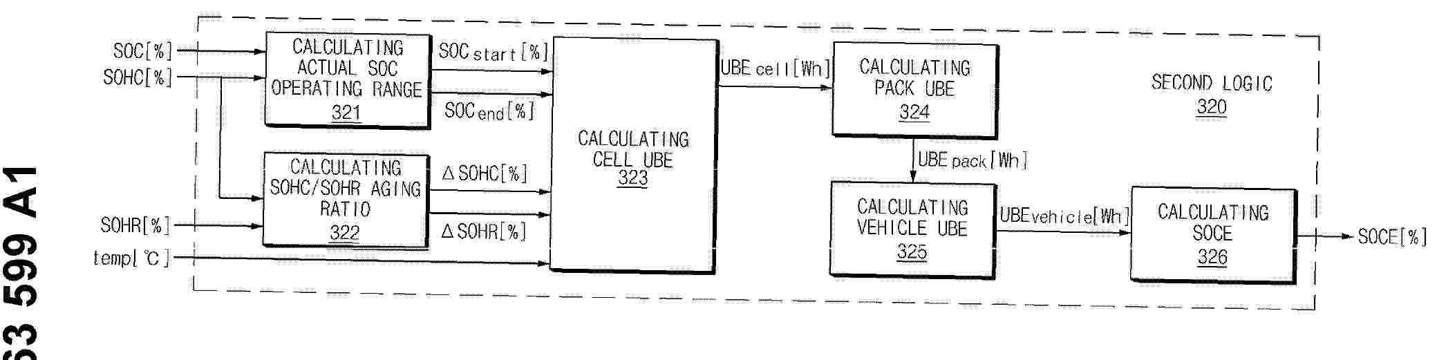
0001 A battery management apparatus includes a memory and a processor operatively connected to the memory. The processor determines an operating range of the battery pack based on battery state variables; calculates degradation rate values of the battery state variables based on energy degradation parameters; measures a usable battery energy (UBE) to be supplied by the battery pack based on a standard test pattern; and estimates a state of certified energy (SOCE) of the battery pack by comparing a measured UBE value with a reference UBE value.
Resumen de: EP4765264A1
The present disclosure relates to an electrode assembly, and an electrode assembly according to one aspect of the present disclosure may include a stacked portion having electrodes and separators alternately interposed, and having a first side and a second side perpendicular to the first side; an electrode tab connected to the electrode and protruding outward from the first side of the stacked portion through each section between the separators; an opening provided on the second side of the stacked portion to allow gas between the separators to flow to the outside; and a fixing member that fixes the electrode and the separator and covers at least a portion of the opening.
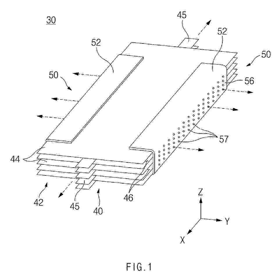
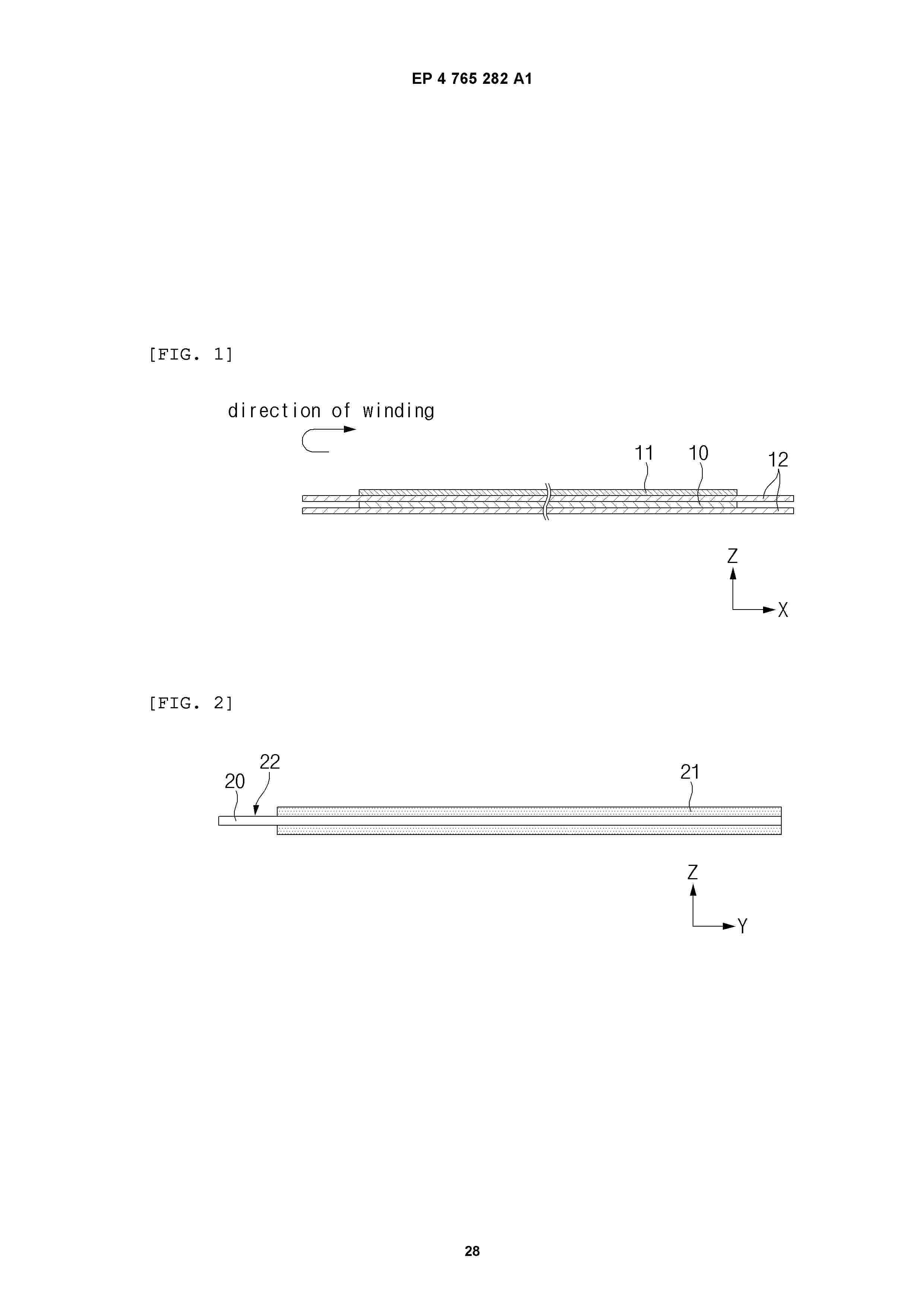
Resumen de: EP4765282A1
0001 The present invention relates to a cylindrical lithium secondary battery comprising: an electrode assembly comprising a positive electrode, a negative electrode, and a separator disposed between the positive electrode and the negative electrode; an electrolyte; and a battery case accommodating the electrode assembly and the electrolyte, wherein the electrolyte comprises a lithium salt and an organic solvent, and a P value defined by Equation 1 below is less than 8.7. P = R H × t a L a v c p a × 100
0002 In Equation 1, H (unit: mm) means a height of the lithium secondary battery, R (unit: mm) means a diameter of the lithium secondary battery, t (unit: µm) means a thickness of the negative electrode, L (unit: g/25 cm<2>) means a loading amount of the negative electrode, P (unit: %) means a porosity of the negative electrode, and V
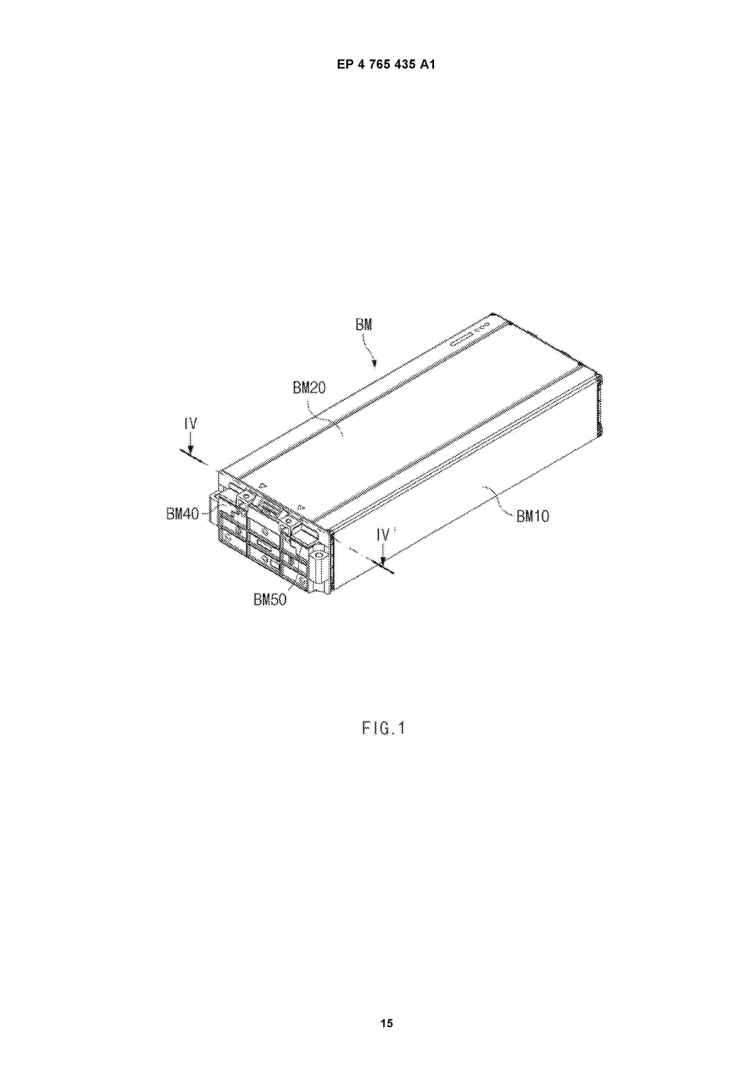
Resumen de: EP4765435A1
0001 A battery module according to the present disclosure includes a secondary battery including an electrode lead; and a busbar configured to be electrically connected to the electrode lead, wherein the busbar includes a support portion to support the electrode lead such that a contact surface with the electrode lead is parallel to an extension direction of the secondary battery.
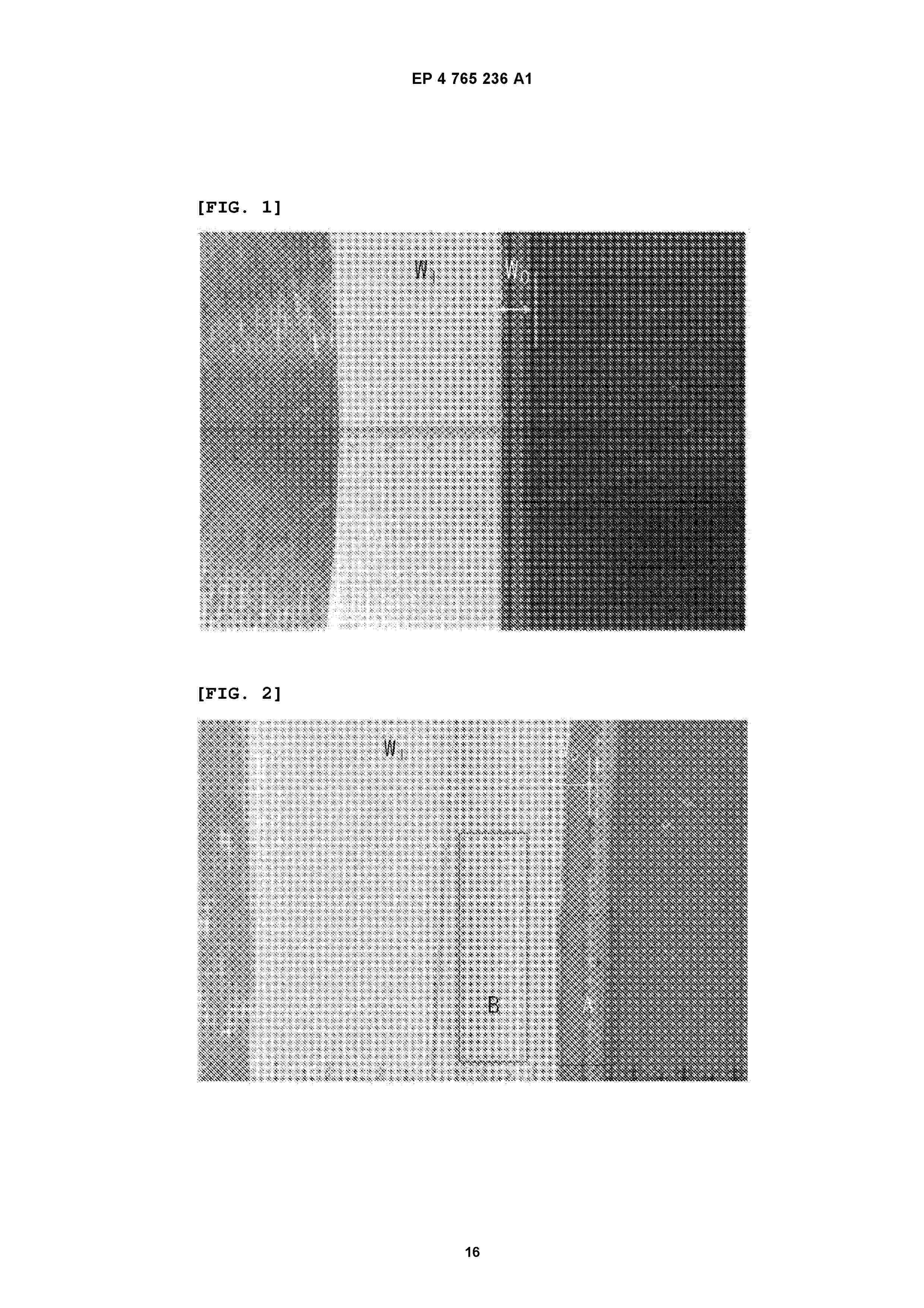
Resumen de: EP4765236A1
0001 A positive electrode according to the present invention includes a current collector, a positive electrode mixture layer provided on a portion on the current collector and including a positive electrode active material, and an insulation layer adjacent to the positive electrode mixture layer and disposed on the current collector on which the positive electrode mixture layer is not provided, wherein the insulation layer includes a non-aqueous binder containing a solution-polymerized conjugated diene-based copolymer, and inorganic particles, so that it is possible to prevent the occurrence of cracks in a region in which the insulation layer and the positive electrode mixture layer overlap each other, and to solve the problem of electrode detachment and the phenomenon of insulation layer depression.
Resumen de: EP4763359A1
Disclosed herein relates to a coating apparatus including: a coating die configured to discharge an electrode slurry toward a substrate and including an electrode slurry discharge port for discharging the electrode slurry; and a flow control block connected to the outer surface of the coating die facing the substrate and extending from the outer surface of the coating die toward the substrate, wherein the flow control block is spaced apart from the electrode slurry discharge port, wherein the width of the flow control block is smaller than the width of the electrode slurry discharge port.
Resumen de: EP4765249A1
0001 A positive electrode active material includes a lithium transition metal oxide including Ni in an amount of 60 at% or more among the transition metals excluding lithium, and is in a form of a single particle made up of one nodule or in a form of a pseudo-single particle that is a complex of 30 or fewer nodules. A proportion of a (003) plane with respect to a total surface area of the positive electrode active material is 40 % or less.
Resumen de: EP4765345A1
0001 Disclosed is a battery pack which includes a plurality of battery modules; a pack case having an inner space configured to accommodate the plurality of battery modules and a wall portion configured to surround the battery modules; and at least one fire-resistance barrier disposed between the battery modules to partition the inner space and detachably assembled to the wall portion, wherein the fire-resistance barrier includes a body portion made of a fire-resistant material, and an edge portion made of a rigid material and configured to surround an outer periphery of the body portion.
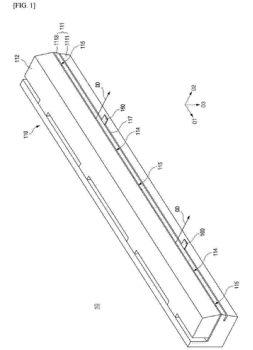
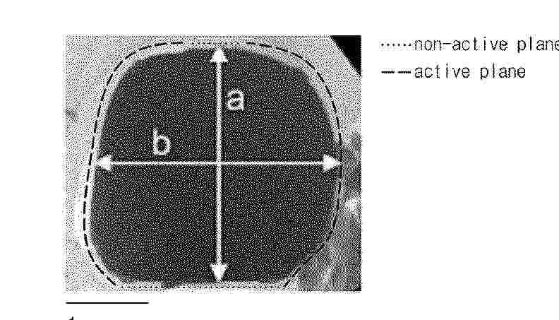
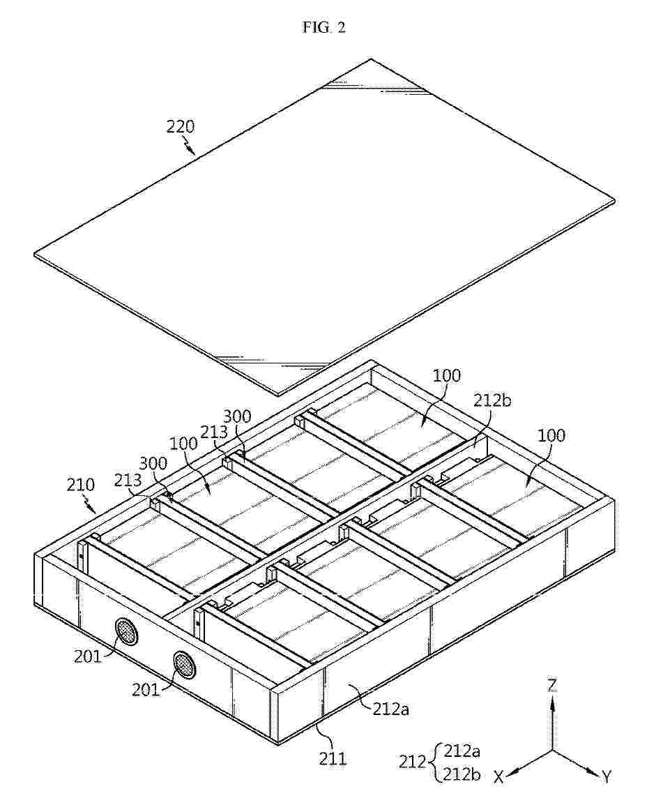
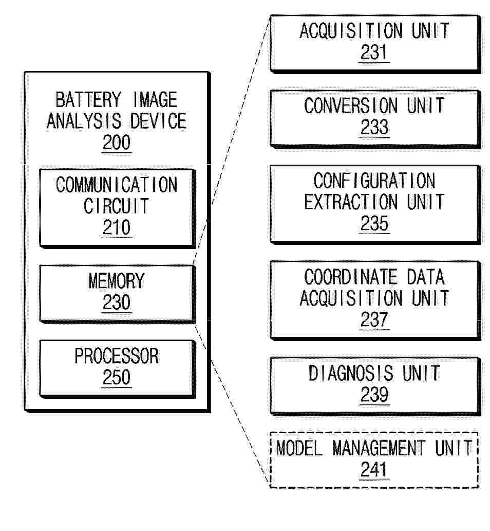
Resumen de: EP4764475A1
0001 A battery image analysis device according to an embodiment disclosed in this document includes an acquisition unit configured to acquire a first image regarding a battery, a conversion unit configured to convert the first image into a second image corresponding to a designated style including one or more of brightness and size of an image based on a deep learning model based on style transfer, a configuration extraction unit configured to extract an image regarding each of the configurations of the battery based on a plurality of pixels included in the second image, a coordinate data acquisition unit configured to acquire coordinate data of pixels of each of the configurations, and a diagnosis unit configured to diagnose a state of the battery based on the coordinate data.
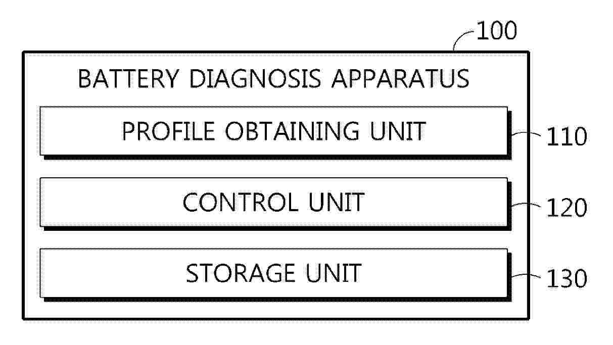
Resumen de: EP4764532A1
0001 A battery diagnosis apparatus according to the present disclosure includes a profile obtaining unit configured to obtain a profile representing a corresponding relationship between a plurality of SOC sections of a battery and a voltage change value of each SOC section; and a control unit configured to determine a target SOC based on a result of comparing the voltage change value and a preset reference change value in each of the plurality of SOC sections, and to diagnose a state of the battery based on a result of comparing the target SOC and a preset reference SOC.
Resumen de: EP4765460A1
The present disclosure relates to a battery module including: a plurality of battery cells; and a deformation member provided on at least one side of the battery cell and configured to change its shape at a specific temperature or higher and increase in volume in a direction toward the one side.
Resumen de: EP4765312A1
0001 The present disclosure relates to a secondary battery. A secondary battery according to an embodiment of the present disclosure may include a cylindrical electrode assembly; a can housing accommodating the electrode assembly; and a top cap assembly coupled to the can housing to cover the electrode assembly, wherein the top cap assembly may include a fire extinguishing module having a fire extinguishing material configured to sprayed onto the electrode assembly; and a top cap disposed above the fire extinguishing module and electrically connected to the electrode assembly to enable electrical connection to the outside, wherein the fire extinguishing module may include a fire extinguishing capsule in which a receiving space accommodating a fire extinguishing material is formed and at least a portion of the fire extinguishing capsule is formed to be meltable; and a support frame that is coupled to the fire extinguishing capsule to support the fire extinguishing capsule and has an opening formed in a portion of the support frame to enable the fire extinguishing material flow to the electrode assembly.
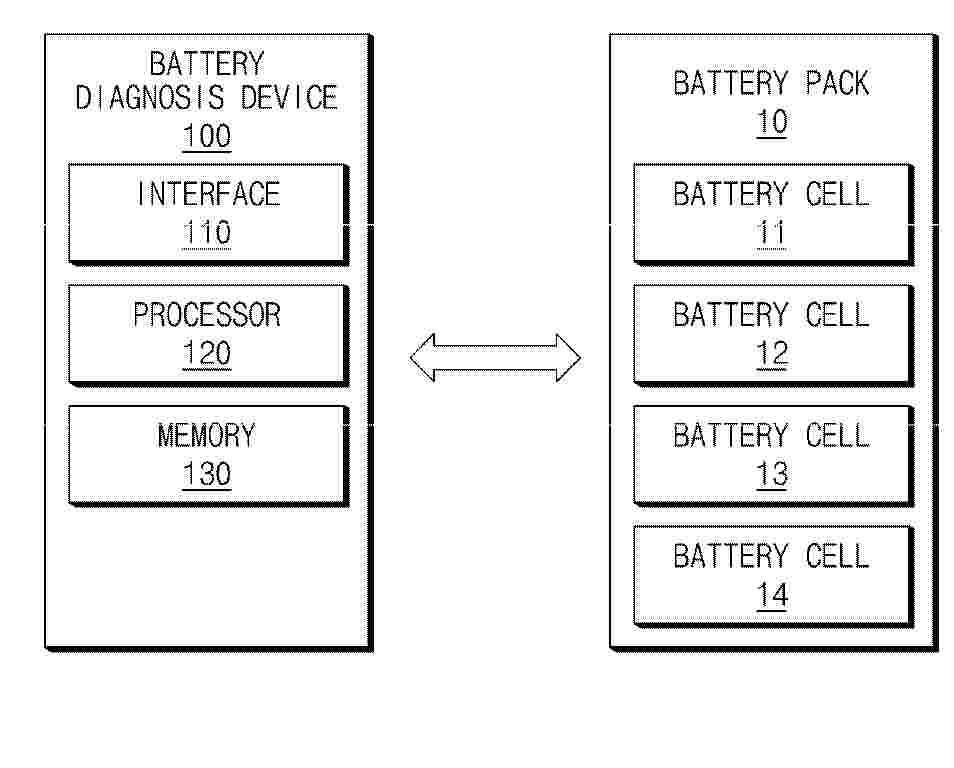
Resumen de: EP4764544A1
0001 A battery diagnosis device according to an embodiment disclosed in this document may include an interface that acquires a first charge profile in the middle of life (MOL) of a battery cell, and at least one processor that predicts a second charge profile using a battery physical model representing a state of a battery and an input parameter that depends on a change in a degradation indicator corresponding to the first charge profile and calculates the degradation indicator of the battery cell corresponding to each of the first charge profile and the second charge profile.
Nº publicación: EP4765375A1 24/06/2026
Solicitante:
LG ENERGY SOLUTION LTD [KR]
LG Energy Solution, Ltd.
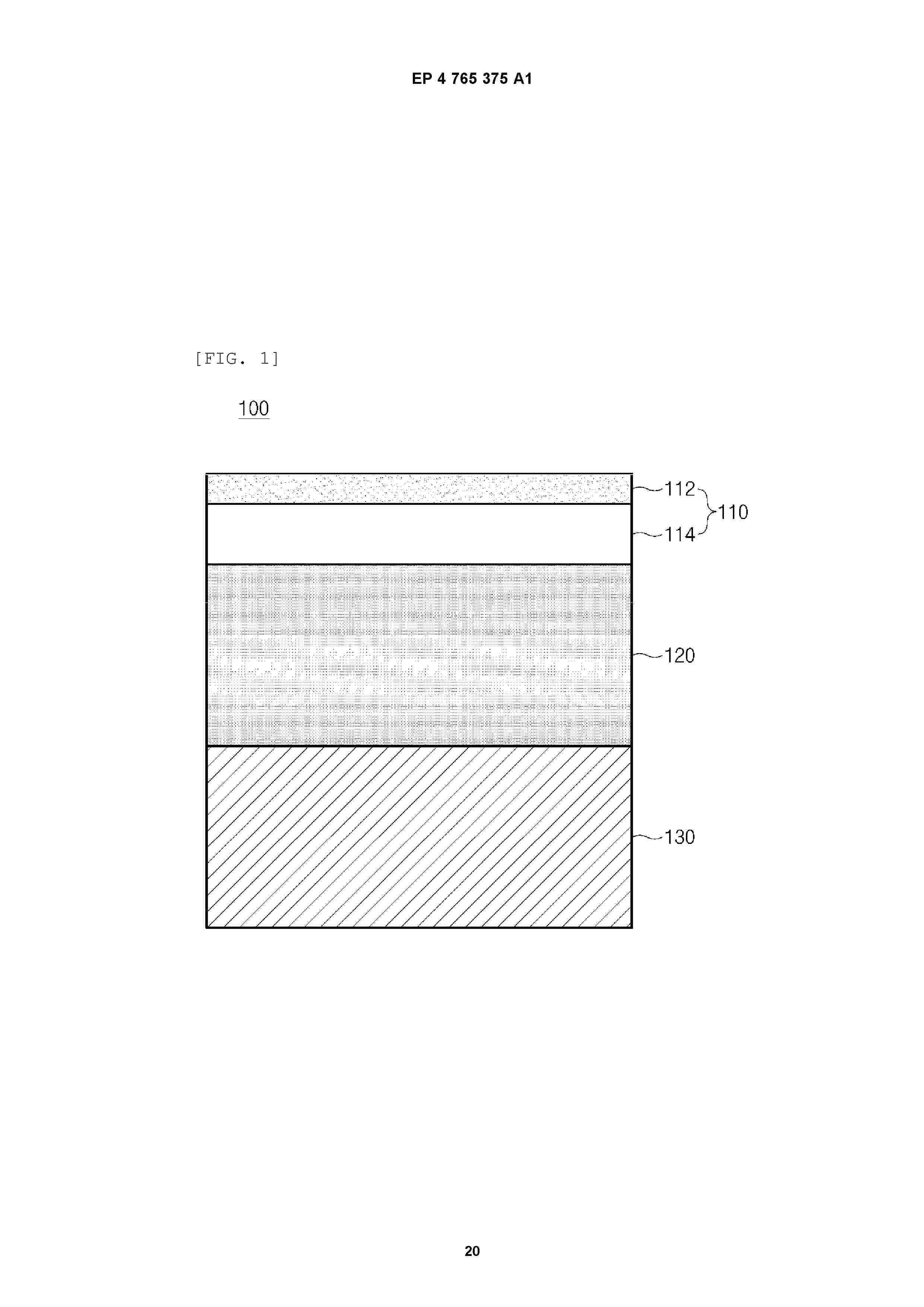
Resumen de: EP4765375A1
0001 The present invention relates to a pouch film laminate including a base material layer, a gas barrier layer, and a sealant layer which are sequentially laminated, wherein the base material layer includes a surface protection layer, and the pouch film laminate has a Max Forming Index A (MFI) expressed by Equation 1 of 15 or more. Max Forming Index A MFI A = PT / AT × TS
0002 In Equation 1, PT is a value of a thickness (µm) of the surface protection layer, AT is a value of a thickness (µm) of the pouch film laminate, and TS is a value of tensile strength (N/15 mm) of the pouch film laminate.
 BOPI
BOPI
 Sede Electrónica