Si deseas distinguir tus productos, servicios o ambos de los de otra empresa, es posible que necesites una marca o nombre comercial. Descubre qué son, en qué consiste su procedimiento de registro y qué implica.

Información sobre los plazos de presentación de solicitudes de transformación de marcas de la Unión Europea en marca nacional española. Más información


Si tienes un nuevo dispositivo, producto o procedimiento que resuelva un problema técnico o tenga una ventaja práctica, existen distintas formas de protegerlo en España y en otros países. Descubre cómo hacerlo.

¿Tu innovación reside en la estética, la ornamentación o la apariencia de tu producto? Protégela mediante un diseño industrial. Descubre qué derechos confiere el registro y cómo realizar la tramitación.

Las indicaciones geográficas protegen el nombre de un producto originario de una zona geográfica, a la cual le debe una determinada calidad, reputación u otra característica. Descubre qué son, en qué consiste su procedimiento de registro y qué beneficios conceden.

Las patentes publicadas en todo el mundo son una valiosa fuente de información científica, técnica y comercial.

Si eres emprendedor/a o una empresa y quieres potenciar y mejorar la rentabilidad de tu negocio protegiendo de forma adecuada los activos intangibles de tu organización, en este espacio encontrarás lo necesario.


 1500
resultados
1500
resultados
 Última actualización
27/06/2026 [07:57:00]
Última actualización
27/06/2026 [07:57:00]


 Resultados 325 a 350 de 1500

Resumen de: EP4765325A1
0001 The present invention relates to an apparatus for manufacturing a secondary battery and a method for manufacturing a secondary battery using the same, and more particularly, to an apparatus for manufacturing a secondary battery, which is capable of quickly and efficiently removing a gas generated inside a cell in an activation process of charging and discharging the cell, solving a problem of a space lack in an facility for manufacturing the secondary battery, and reducing cost of the manufacturing facility, and a method for manufacturing a secondary battery using the same.

Resumen de: EP4765427A1
The present disclosure relates to a battery module including: a cell assembly including a plurality of battery cells; a bus-bar frame provided on at least one side of the cell assembly; a module case including a body frame configured to cover some sides of the cell assembly, and an end frame coupled to the body frame and configured to cover the bus-bar frame; and a blocking member provided inside a joint between the body frame and the end frame, and configured to cover a portion of the cell assembly.
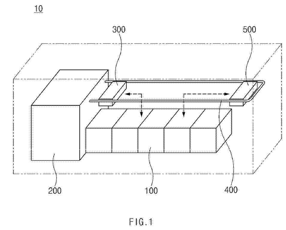
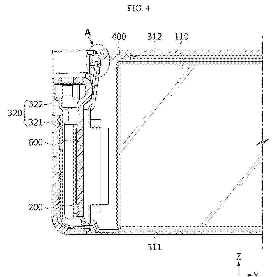
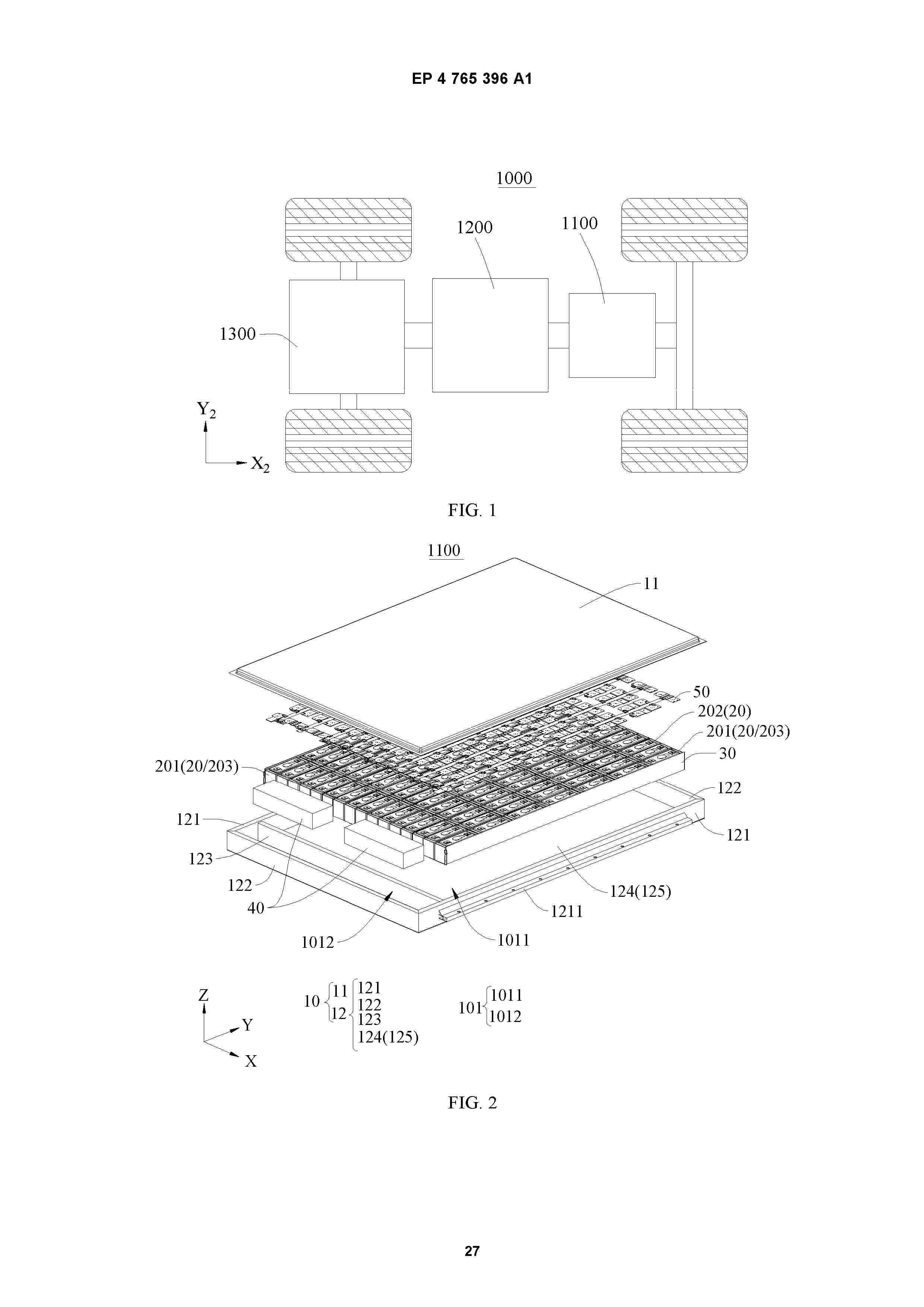
Resumen de: EP4765396A1
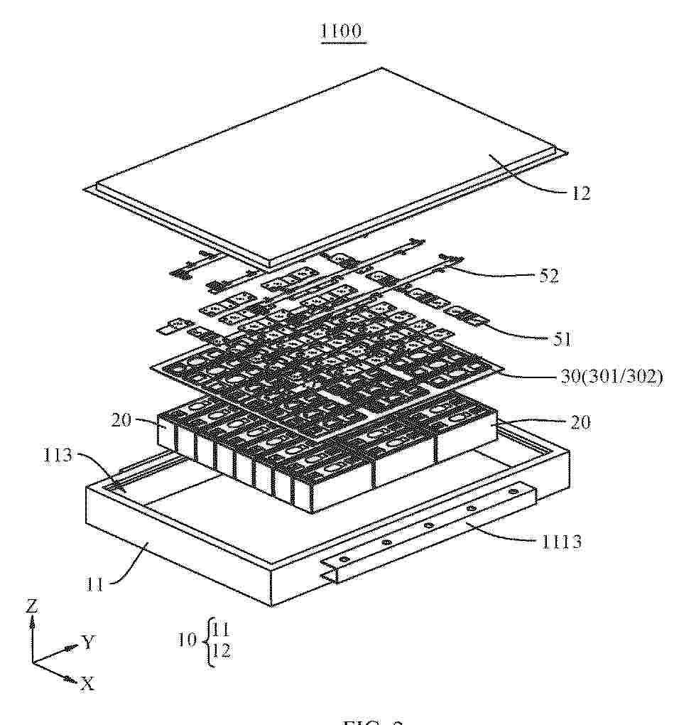
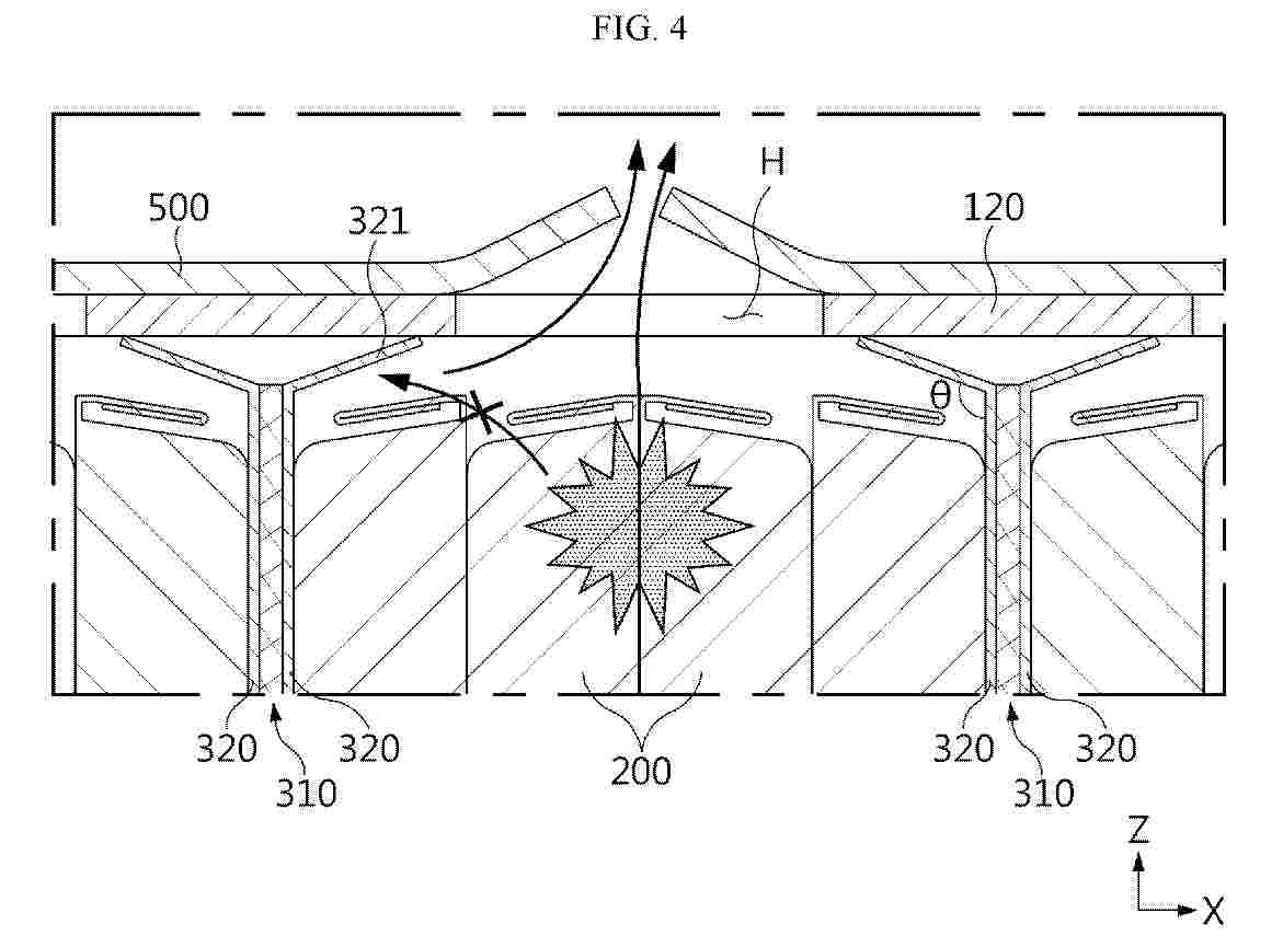
A battery and an electric device. A battery (1100) comprises a box body (10), insulating members (30), and at least one battery cell (20). The box body (10) comprises first side beams (121) and second side beams (122), and the first side beams (121) and the second side beams (122) are connected and define an accommodating space (101). The at least one battery cell (20) is located in the accommodating space (101), battery cells adjacent to the first side beams (121) are first battery cells (201), the maximum area surface of each first battery cell (201) is a first surface (21), and the first surface (21) of the first battery cell (201) faces the corresponding first side beam (121). The insulating members (30) are located in the accommodating space (101), and each insulating member (30) is provided between the first battery cells (201) and the corresponding first side beam (121), so that when the first side beam (121) is impacted, the first surfaces (21) of the first battery cells (201) bear impact, reducing the impact deformation of the first battery cells (201), reducing the short-circuit risk of the first battery cells (201), thereby improving the use reliability of the battery (1100).
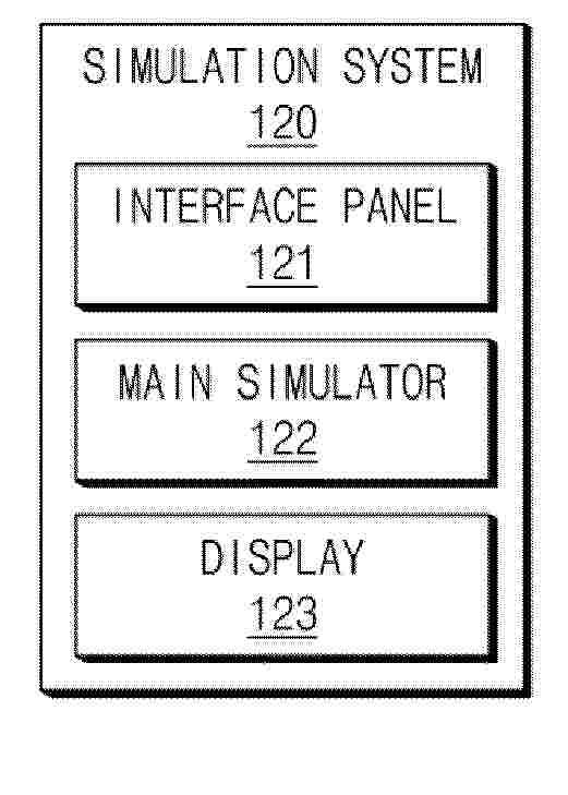
Resumen de: EP4765073A1
0001 According to some embodiments, a simulation system includes an interface panel configured to receive a manipulation input from a worker, a main simulator configured to load training content reproducing processes of manufacturing a battery through electrode notching based on the manipulation input and to provide the training content to the worker through interaction with the worker, and a display configured to display detailed images of the processes based on characteristics of the training content.
Resumen de: EP4765436A1
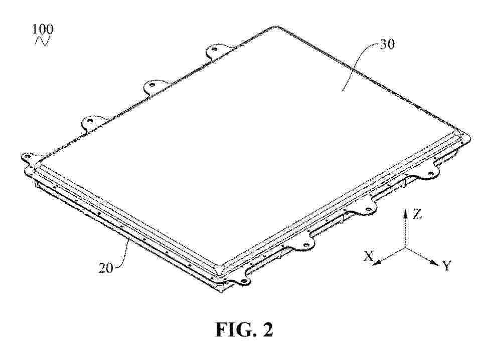
A battery and an electrical device. The battery comprises a case (10), a connector (30) and at least one battery cell (20), wherein the at least one battery cell (20) is located in the case (10); and the connector (30) comprises a first connecting portion (31) and a second connecting portion (32) connected to each other, the first connecting portion (31) being fixedly connected to the at least one battery cell (20), and the second connecting portion (32) being fixedly connected to the case (10), so that the connector (30) can stably connect the battery cell (20) and the case (10) together, the connection reliability of the battery cell (20) and the case (10) is improved, and the structural strength and rigidity of the battery are improved, thereby improving the use reliability of the battery, and prolonging the service life of the battery.
Resumen de: EP4765389A1
Provided are a battery (100) and an electrical apparatus, which are applicable to the technical field of battery (100). The electrical apparatus includes the battery (100), the battery (100) including a battery unit (10) and a box body (20), where the battery unit (10) includes at least one battery cell (1). The box body (20) is provided with two first walls (21) opposite to each other along a first direction (Y), the two first walls (21) being each connected with a first connection member (22) configured to be connected to an external device, where in the first direction (Y), the battery unit (10) is disposed between the two first walls (21) and is position-limited by the first walls (21). In a case where the first connection member (22) is connected to the external device, the external device can constrain relative positions of the two first walls (21) in the first direction (Y), such that the two first walls (21) can constrain the battery unit along the first direction (Y) to effectively resist the expansion of the battery cell (1) and to reduce or eliminate the provision of structures such as an expansion beam, which helps to reduce the cost of the battery (100).
Resumen de: EP4765348A1
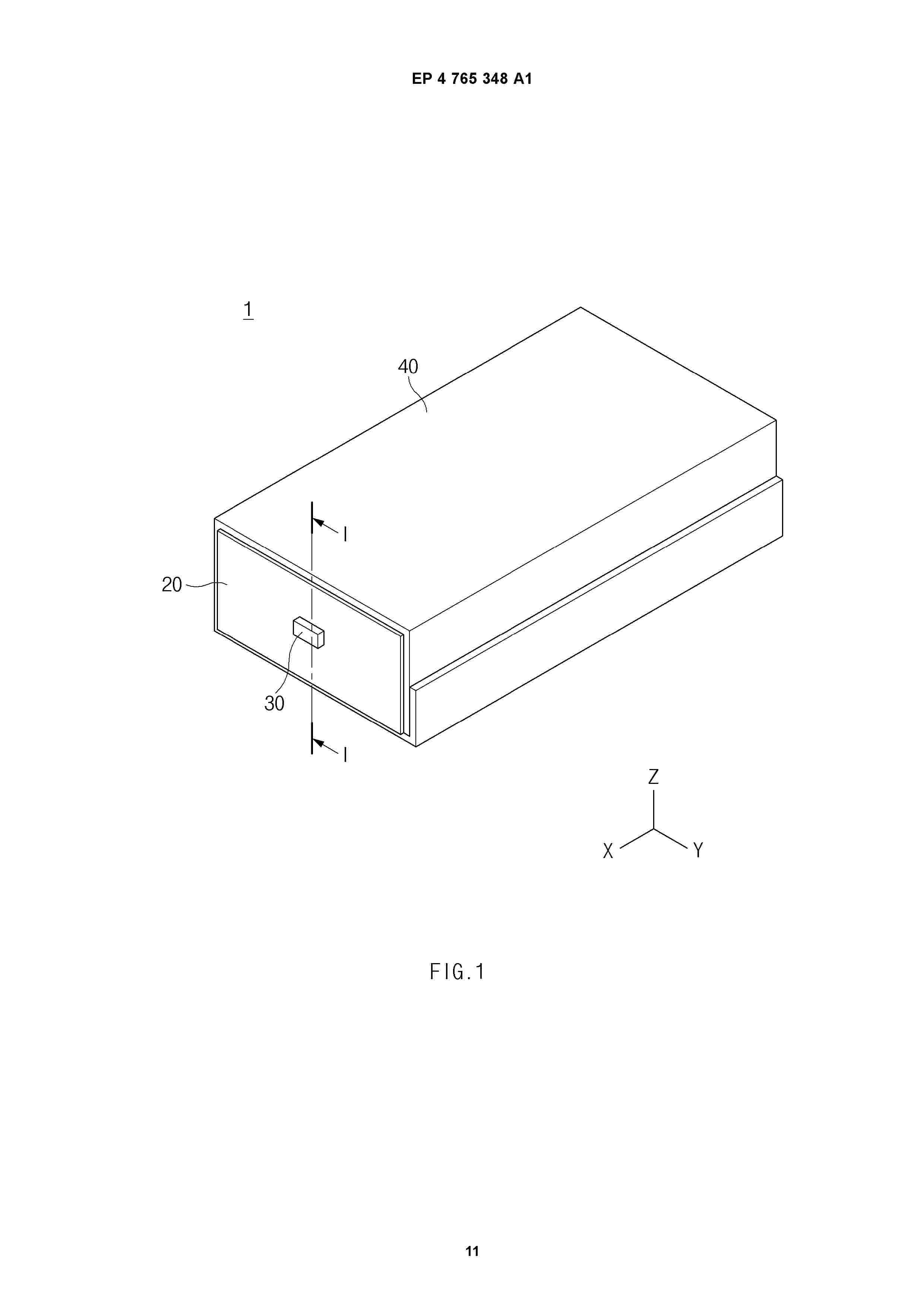
0001 The present disclosure relates to a secondary battery. A secondary battery according to an aspect of the present disclosure may include an electrode assembly extending in a first direction; a cap including a cover portion disposed on one side of the electrode assembly in the first direction and an extension portion extending from the cover portion toward the electrode assembly; and an exterior film surrounding the electrode assembly and coupled to the extension portion. The exterior film may include an accommodating portion that circumferentially surrounds the electrode assembly; a rim portion provided on one side of the accommodating portion in the first direction; and a coupling portion provided between the accommodating portion and the rim portion, coupled to the extension portion, and located at a predetermined first distance (d1) from a reference surface among outer surfaces of the cover portion, the reference surface facing the first direction.
Resumen de: EP4765303A1
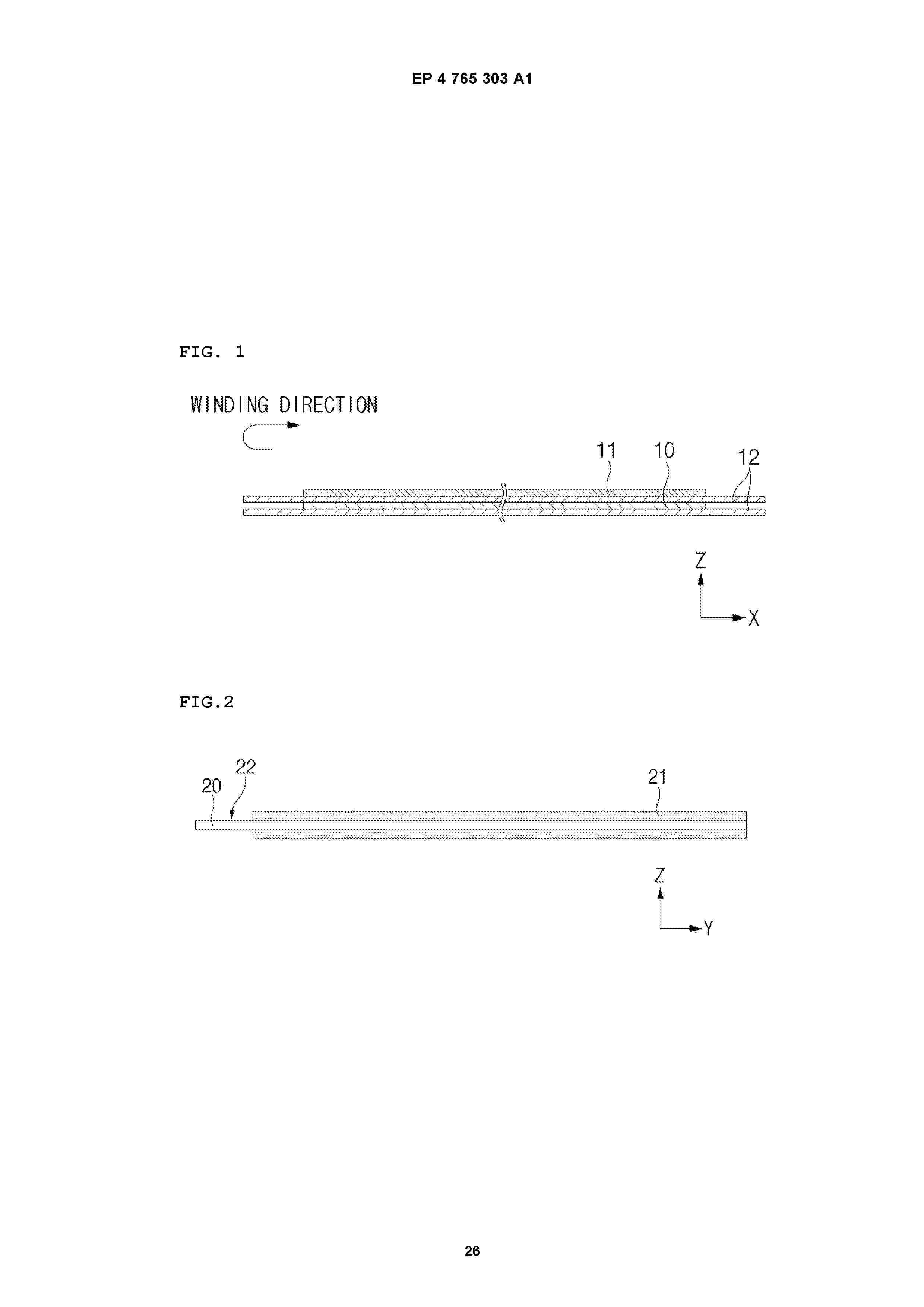
The present invention relates to a lithium secondary battery in which a value of X defined by Equation 1 described above is in a range of 7 m2 to 16 m2.
Resumen de: EP4765316A1
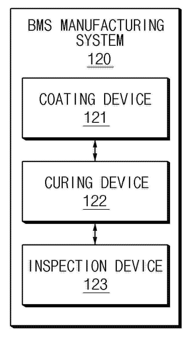
According to some embodiments, a BMS manufacturing system include a coating device configured to apply a coating material to a battery management system (BMS) circuit including circuit components mounted on a circuit board, a curing device configured to irradiate a surface of the BMS circuit with curing light to cure the coating material, and an inspection device configured to cause heat generation of the BMS circuit by performing a functional inspection of the BMS circuit to perform heat treatment on a portion of the coating material not exposed to the curing light.
Resumen de: EP4764550A1
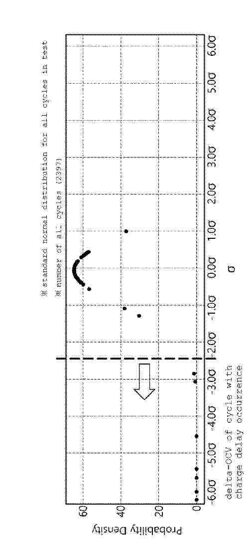
A battery diagnosis method according to an embodiment of the present invention relates to a method for diagnosing a cell abnormality during charge/discharge testing for a module including a plurality of cells, wherein the battery diagnosis method may comprise the steps of: collecting battery-state-related measurement values for respective cycles of the charge/discharge testing; determining whether a voltage deviation between cells within the module among the battery-state-related measurement values is greater than or equal to a set threshold value; if the voltage deviation between cells within the module is greater than or equal to the set threshold value, calculating data representing the amount of capacity changes in the module relative to the amount of changes in a charging voltage or a discharging voltage; and identifying a trend of the data representing the amount of capacity changes in the module relative to the amount of changes in the charging voltage or the discharging voltage, so as to determine an abnormal cell within the module.
Resumen de: EP4764548A1
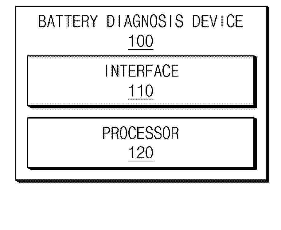
A battery diagnosis device according to an embodiment disclosed in this document may include an interface configured to acquire a magnetic field image of a battery cell and one or more processors configured to generate magnetic field linear data corresponding to a magnetic field intensity at a specific location of the battery cell based on the magnetic field image and diagnose an abnormality of the battery cell based on the magnetic field linear data.
Resumen de: EP4764570A1
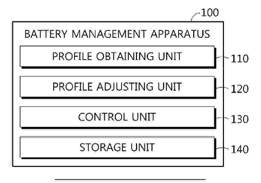
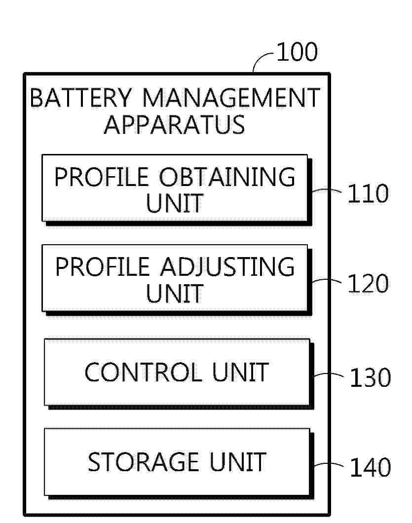
0001 A battery management apparatus according to the present disclosure includes a profile obtaining unit configured to obtain a battery profile representing a corresponding relationship between voltage and capacity of a battery; a profile adjusting unit configured to adjust a preset reference positive electrode profile and a reference negative electrode profile to correspond to the battery profile, thereby generating a positive electrode profile and a negative electrode profile of the battery; and a control unit configured to extract a parameter for the battery from at least one of the positive electrode profile and the negative electrode profile and determine an available lithium increase rate of the battery based on the extracted parameter.
Resumen de: EP4764569A1
A battery management apparatus according to the present disclosure includes a profile obtaining unit configured to obtain a battery profile representing a corresponding relationship between voltage and capacity of a battery; a profile adjusting unit configured to adjust a preset reference positive electrode profile and a reference negative electrode profile to correspond to the battery profile, thereby generating a positive electrode profile and a negative electrode profile of the battery; and a control unit configured to extract a parameter for the battery from at least one of the positive electrode profile and the negative electrode profile and determine an available lithium increase rate of the battery based on the extracted parameter.
Resumen de: US2025313125A1
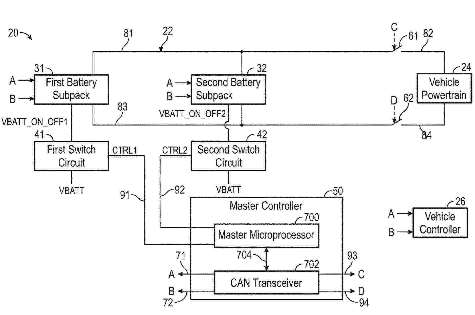
A battery system includes a battery subpack having first and second battery cells, a cell monitoring circuit, and a subpack microprocessor. The cell monitoring circuit obtains first and second voltage values. A first switch circuit applies an operational voltage to the subpack microprocessor in response to a first control signal from a master controller. The master controller sends a first message that requests the first and second voltage values from the subpack microprocessor. The master controller stops generating the first control signal to induce the first switch circuit to remove the operational voltage from the subpack microprocessor when the master controller does not receive a second message having the first and second voltage values from the subpack microprocessor within a predetermined amount of time after sending the first message.
Resumen de: EP4765426A1
The present disclosure relates to a battery module including: a module case having an inner space formed therein; a plurality of battery cells configured to be stored in the inner space of the module case; and a barrier including a first blocking member provided between the plurality of battery cells and a second blocking member provided on at least one side of the first blocking member and configured such that its end is bent.
Resumen de: EP4765563A1
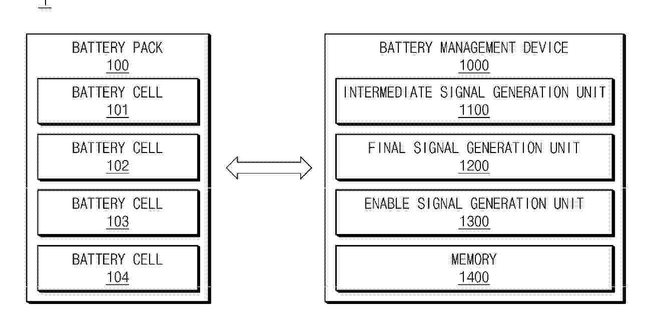
A battery management device according to an embodiment disclosed in this document includes an intermediate signal generation unit that generate an intermediate signal related to operation control of a contactor corresponding to each of a first battery pack and a second battery pack connected in parallel with the first battery pack and a final signal generation unit that generates a final signal for controlling an electrical connection of the contactor corresponding to the second battery pack based on a comparison result between a link voltage, which is a voltage applied to nodes to which the first battery pack and the second battery pack are connected by the first battery pack, and a pack voltage applied to a positive contactor corresponding to the second battery pack, and the intermediate signal.
Resumen de: EP4765412A1
A pouch type battery case according to the present invention includes a cup portion provided with an accommodation space for accommodating an electrode assembly, a terrace portion formed along a perimeter of the accommodation portion, and at least one gas discharge portion, wherein each of the gas discharge portions includes a through hole formed in at least one of the cup portion or the terrace portion, a gas permeable film covering the through hole from the inside of the battery case, and a polymer-based protection film covering the through hole from the outside of the battery case, and the gas discharge portion having the structure described above exhibits excellent performance in preventing moisture penetration from the outside while continuously discharging gas, and thus may provide a pouch type secondary battery having improved safety and lifespan.
Resumen de: EP4763771A2
An electrode assembly manufacturing apparatus includes: a wound separator in which two or more layers of separators are stacked and wound; a separator supply unit that individually separates and supplies the two or more layers of separators from the wound separator; a first electrode supply unit that supplies a first electrode; a second electrode supply unit that supplies a second electrode; and a winding unit that individually stacks and winds each separated separator, between the first electrode and the second electrode and on an outer side of the first electrode or the second electrode.
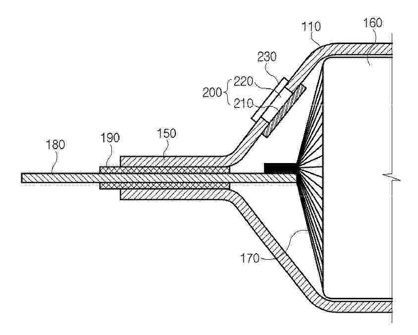
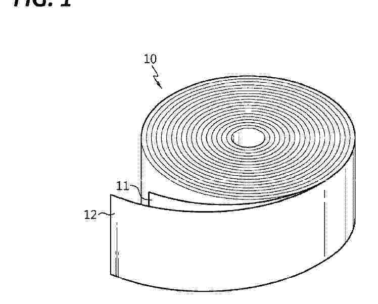
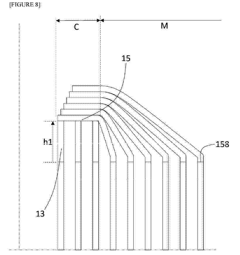
Resumen de: EP4765461A1
0001 Provided are a cylindrical electrode assembly and a tab-less secondary battery employing the same which uses the ends of electrode sheets without active material as electrode tabs. The electrode assembly structure prevents the risk of short circuits in the core section thereof and secures an additional current path in the core section, thereby reducing heat generation due to internal resistance. The core section of the electrode sheet is provided with a plateau that protrudes axially outward and extends in the lengthwise direction from an incision groove defining a segmented tab, the segmented tab is bent radially inward, and the upper end of the plateau is in contact with and is electrically connected to the unbent segmented tab.
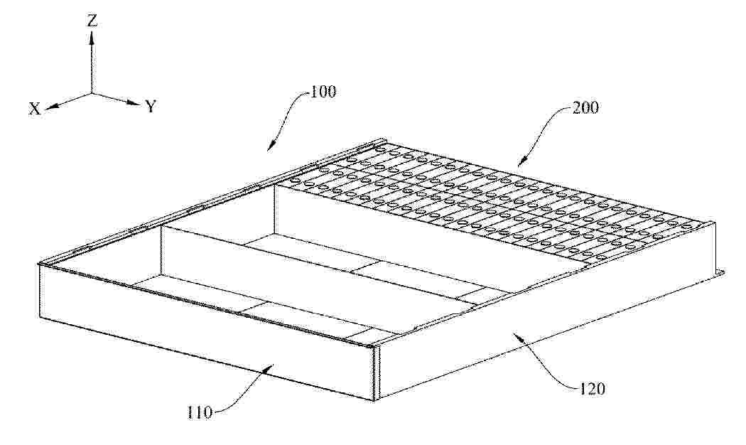
Resumen de: EP4765400A1
0001 A battery frame and a battery pack. The battery frame includes two X-direction side plates (110), two Y-direction side plates (120) and a cover plate (140). The Y-direction side plate includes a lateral plate (121) and a vertical plate (122) erected on the lateral plate (121). The lateral plate (121) and the vertical plate (122) are of an integrated structure. The two Y-direction side plates (120) are oppositely arranged along a direction Y and are connected via the lateral plates (121). The lateral plates (121) is provided with a plurality of first coolant channels (1211) arranged at intervals in the direction Y. The two X-direction side plates (110) are oppositely arranged along a direction X. Two ends of each Y-direction side plate along the direction X are respectively connected to the two X-direction side plates. The two Y-direction side plates (120) and the two X-direction side plates (110) are enclosed to form a frame structure (100) with an opening at one end. The cover plate (140) covers the opening of the frame structure.
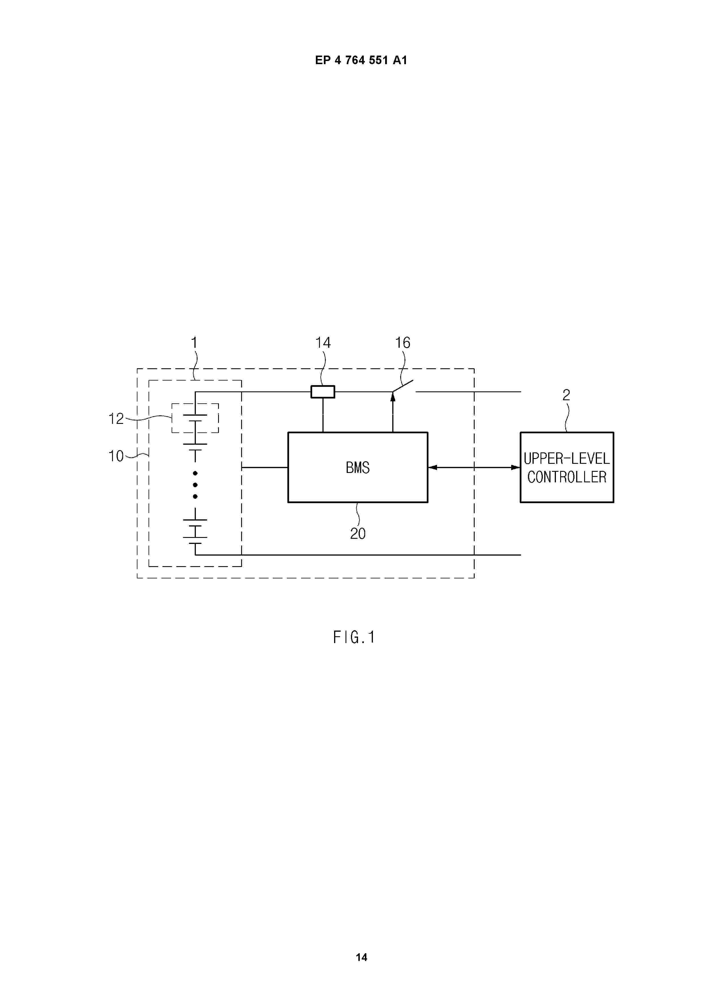
Resumen de: EP4764551A1
0001 A battery diagnosis device according to an embodiment of this document includes a memory configured to store at least one instruction and at least one processor configured to execute the at least one instruction, the at least one processor is configured to identify a set of data measured from a battery cell while the battery cell is in use and times at which the set of data is acquired, identify a plurality of data regions including at least one of a plurality of first ranges that divide a first state variable of the battery cell into a first size, a plurality of second ranges that divide a second state variable of the battery cell into a second size, a plurality of third ranges that divide a third state variable of the battery cell into a third size, or any combination thereof, and diagnose a state of the battery cell based on battery data regions including the set of data among the plurality of data regions, and holding times corresponding to each of the battery data regions among the times, and the data includes at least one of a value of the first state variable, a value of the second state variable, a value of the third state variable, or any combination thereof.
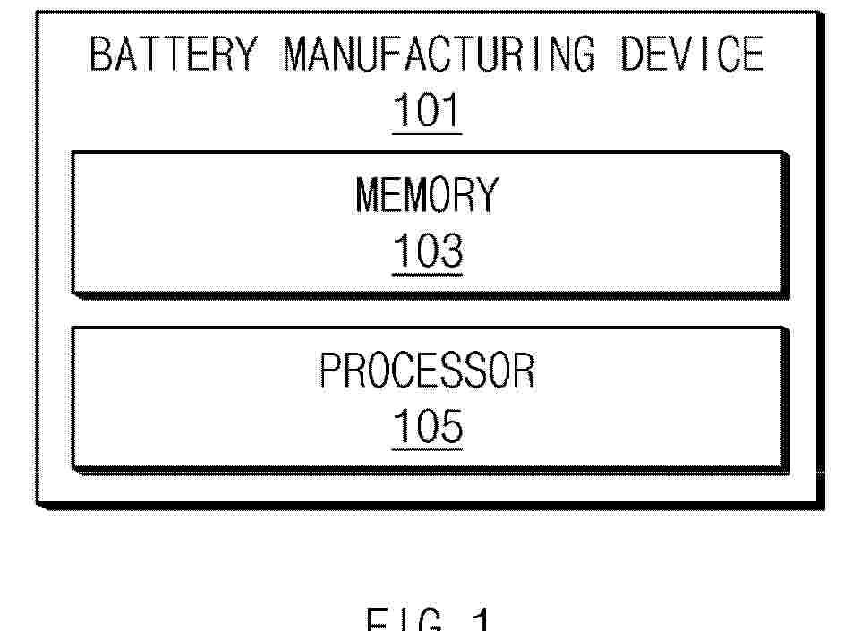
Resumen de: EP4765273A1
0001 A battery manufacturing device according to an embodiment of this document may include a memory configured to store at least one instruction, and at least one processor configured to execute the at least one instruction, in which the at least one processor is configured to, in a winding process of a battery, identify a movement distance that an electrode plate moves in a left direction or right direction of a direction in which the electrode plate advances before being wound, as a speed at which the electrode plate is wound is changed, determine a tension for pulling the electrode plate in a direction opposite to the direction in which the plate advances, based on the movement distance, and wind the electrode plate based on the tension.
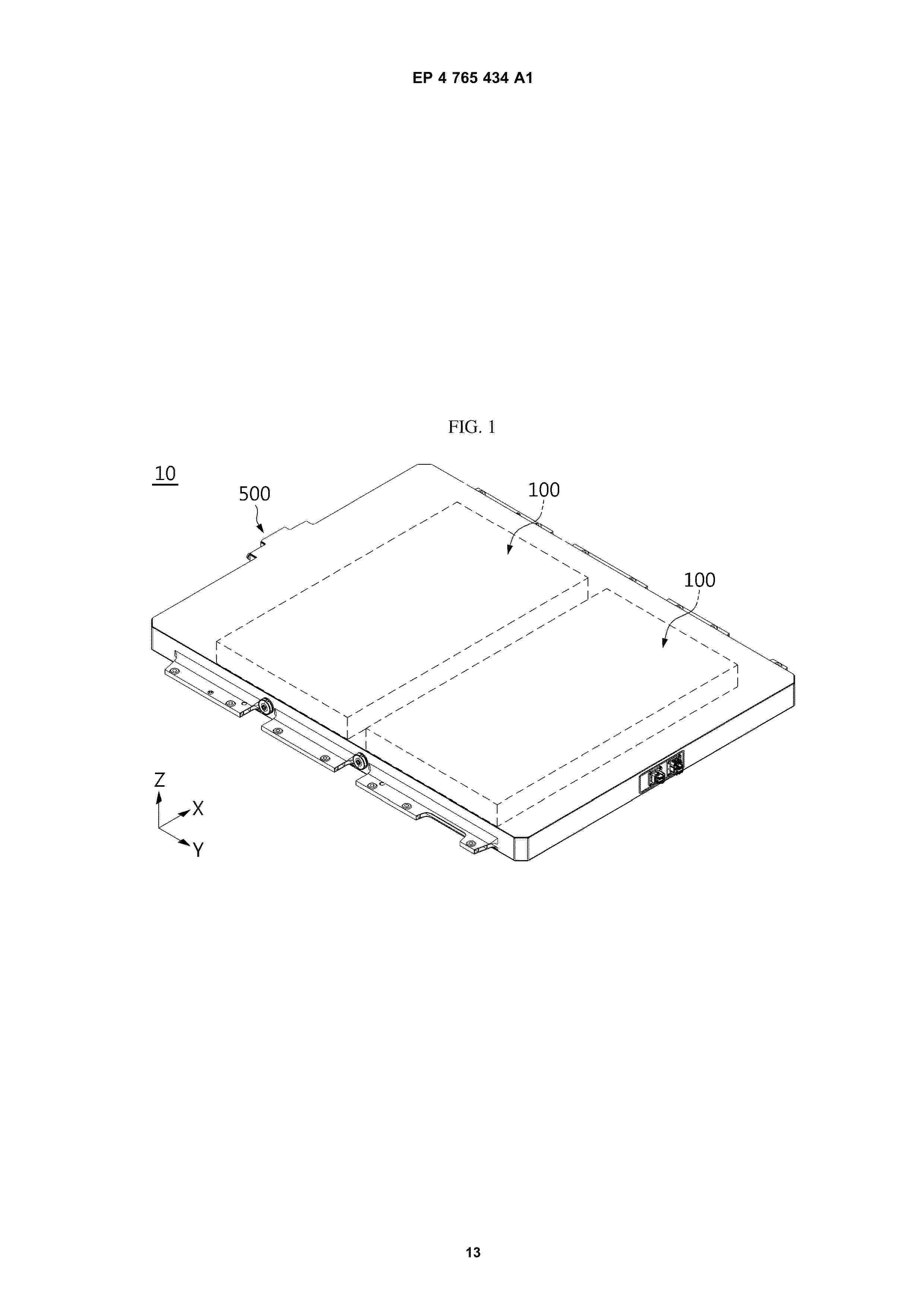
Resumen de: EP4765434A1
A battery pack according to the present disclosure includes a plurality of battery cells; a bus-bar assembly disposed on one side of the plurality of battery cells and including a sub-bus-bar unit connected to electrodes of the plurality of battery cells; and a metal member configured to support the plurality of battery cells at a bottom of the bus-bar assembly, wherein the sub-bus-bar unit includes a one-way connection bus-bar connected to the electrodes of the battery cells on one side of the sub-bus-bar unit in a width direction, and wherein the metal member is partially connected to the one-way connection bus-bar at a predetermined position to have a predetermined conductive area so as to avoid current differences in the one-way connection bus-bar.
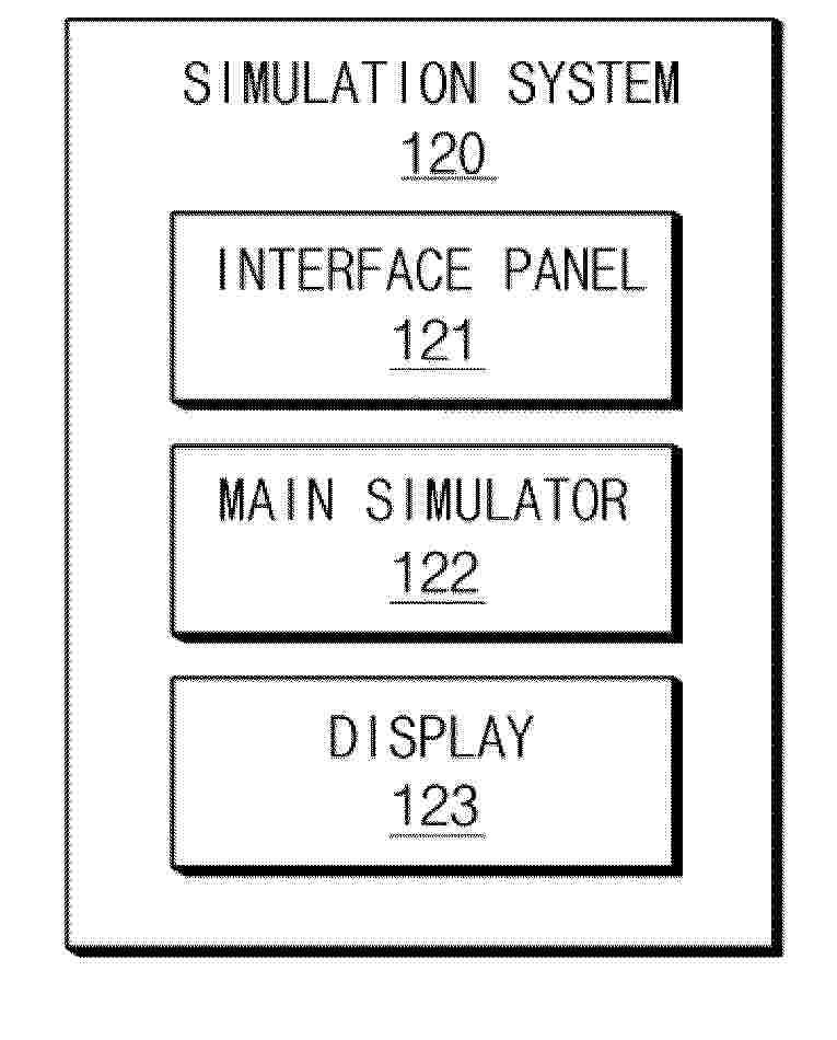
Resumen de: EP4765075A1
According to some embodiments, a simulation system includes an interface panel configured to provide an HMI environment for receiving a manipulation input of a virtual slitting facility performing a slitting process for a battery electrode, and a main simulator configured to provide facility operation content for displaying a process of operating the virtual slitting facility based on the manipulation input to form a plurality of slitting electrodes and provide quality check content for checking an external dimension of the plurality of slitting electrodes to determine whether the slitting process is defective, and a display configured to provide an MES function for managing the slitting process.
Nº publicación: EP4764562A1 24/06/2026
Solicitante:
LG ENERGY SOLUTION LTD [KR]
LG Energy Solution, Ltd.
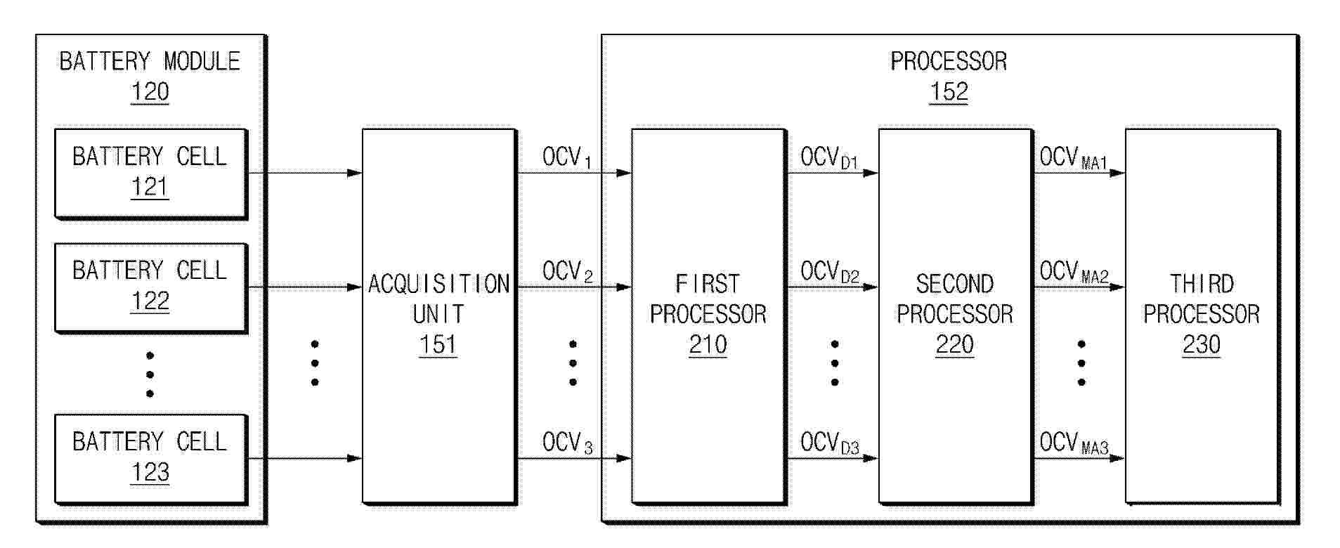
Resumen de: EP4764562A1
A battery diagnosis device according to an embodiment disclosed in this document may include an interface that acquires open circuit voltage (OCV) data of a battery cell and one or more processors that calculate an OCV deviation representing a difference between an average OCV corresponding to a specific point in time and an OCV of a battery cell for each of a plurality of battery cells included in a specific battery module based on the OCV data, acquire a plurality of OCV moving averages by applying different weighted moving averages to the OCV deviation, and diagnose an abnormality of the battery cell based on the plurality of OCV moving averages.
 BOPI
BOPI
 Sede Electrónica