Si deseas distinguir tus productos, servicios o ambos de los de otra empresa, es posible que necesites una marca o nombre comercial. Descubre qué son, en qué consiste su procedimiento de registro y qué implica.

Información sobre los plazos de presentación de solicitudes de transformación de marcas de la Unión Europea en marca nacional española. Más información


Si tienes un nuevo dispositivo, producto o procedimiento que resuelva un problema técnico o tenga una ventaja práctica, existen distintas formas de protegerlo en España y en otros países. Descubre cómo hacerlo.

¿Tu innovación reside en la estética, la ornamentación o la apariencia de tu producto? Protégela mediante un diseño industrial. Descubre qué derechos confiere el registro y cómo realizar la tramitación.

Las indicaciones geográficas protegen el nombre de un producto originario de una zona geográfica, a la cual le debe una determinada calidad, reputación u otra característica. Descubre qué son, en qué consiste su procedimiento de registro y qué beneficios conceden.

Las patentes publicadas en todo el mundo son una valiosa fuente de información científica, técnica y comercial.

Si eres emprendedor/a o una empresa y quieres potenciar y mejorar la rentabilidad de tu negocio protegiendo de forma adecuada los activos intangibles de tu organización, en este espacio encontrarás lo necesario.


 557
resultados
557
resultados
 Última actualización
02/04/2026 [06:49:00]
Última actualización
02/04/2026 [06:49:00]


 Resultados 475 a 500 de 557

Resumen de: DE102024208918A1
Die Erfindung betrifft ein Verfahren zum Betreiben eines Brennstoffzellensystems (1), bei dem einem Brennstoffzellenstapel (2) über einen Anodenkreis (3) eines Anodensubsystems (4) ein Anodengas zugeführt wird, das Wasserstoff aus einem Tank (5) sowie rezirkuliertes Anodengas enthält, und bei dem rezirkuliertes Anodengas von Zeit zu Zeit durch Öffnen eines in den Anodenkreis (3) integrierten, elektromagnetisch ansteuerbaren Purgeventils (6) aus dem Anodenkreis (3) entfernt und durch Wasserstoff aus dem Tank (5) ersetzt wird. Erfindungsgemäß wird zur indirekten Ermittlung der Zusammensetzung des Anodengases das Purgeventil (6) angesteuert und vom Verlauf eines Strom- oder Spannungssignals der Ansteuerung wird auf die Zusammensetzung des Anodengases geschlossen.Darüber hinaus betrifft die Erfindung ein Steuergerät für ein Brennstoffzellensystem zur Ausführung von Schritten eines erfindungsgemäßen Verfahrens.

Resumen de: DE102024208921A1
Die vorgestellte Erfindung betrifft ein Verfahren (100) zur Diagnose eines Brennstoffzellensystems (200).Das vorgestellte Verfahren (100) umfasst:- Schließen (101) eines Anodensubsystems und eines Kathodensubsystems eines Brennstoffzellenstapels (201) des Brennstoffzellensystems (200),- Ermitteln (103) einer Dauer einer Stagnationsphase,- Zuordnen (105) der ermittelten Dauer zu einem Zustand des Brennstoffzellensystems (200),- Ausgeben (107) des der ermittelten Dauer zugeordneten Zustands,wobei die Stagnationsphase zu einem ersten Zeitpunkt (t1) beginnt, zu dem ein Anodendruck (111) in dem Anodensubsystem einem Kathodendruck (113) in dem Kathodensubsystem entspricht, undwobei die Stagnationsphase zu einem zweiten Zeitpunkt (t2) endet, zu dem eine Änderungsrate eines Verlaufs des Anodendrucks (111) und/oder des Kathodendrucks (113) über einem vorgegebenen Schwellenwert liegt.
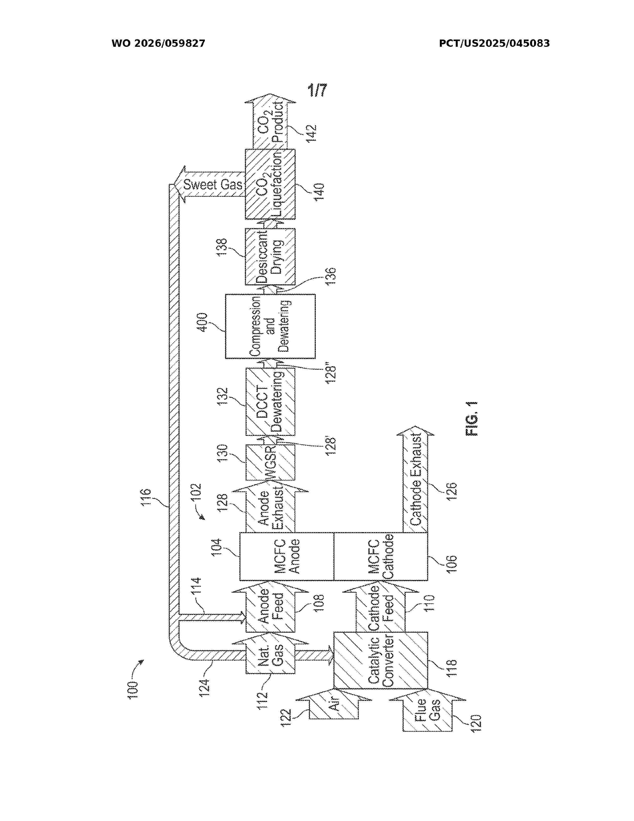
Resumen de: WO2026059827A1
A fuel cell system includes a molten carbonate fuel cell module including an anode section configured to output an anode exhaust stream including carbon dioxide and hydrogen and a cathode section configured to receive a cathode input stream. The fuel cell system further includes a drying system configured to receive and remove water from the anode exhaust stream and to output a dried anode exhaust stream comprising less than 0.1 percent water and a carbon dioxide solvent extraction system configured to receive the dried anode exhaust stream, expose the dried anode exhaust stream to a physical solvent to absorb carbon dioxide, output a carbon dioxide product stream comprising at least 99 percent carbon dioxide, and output a sweet gas stream.
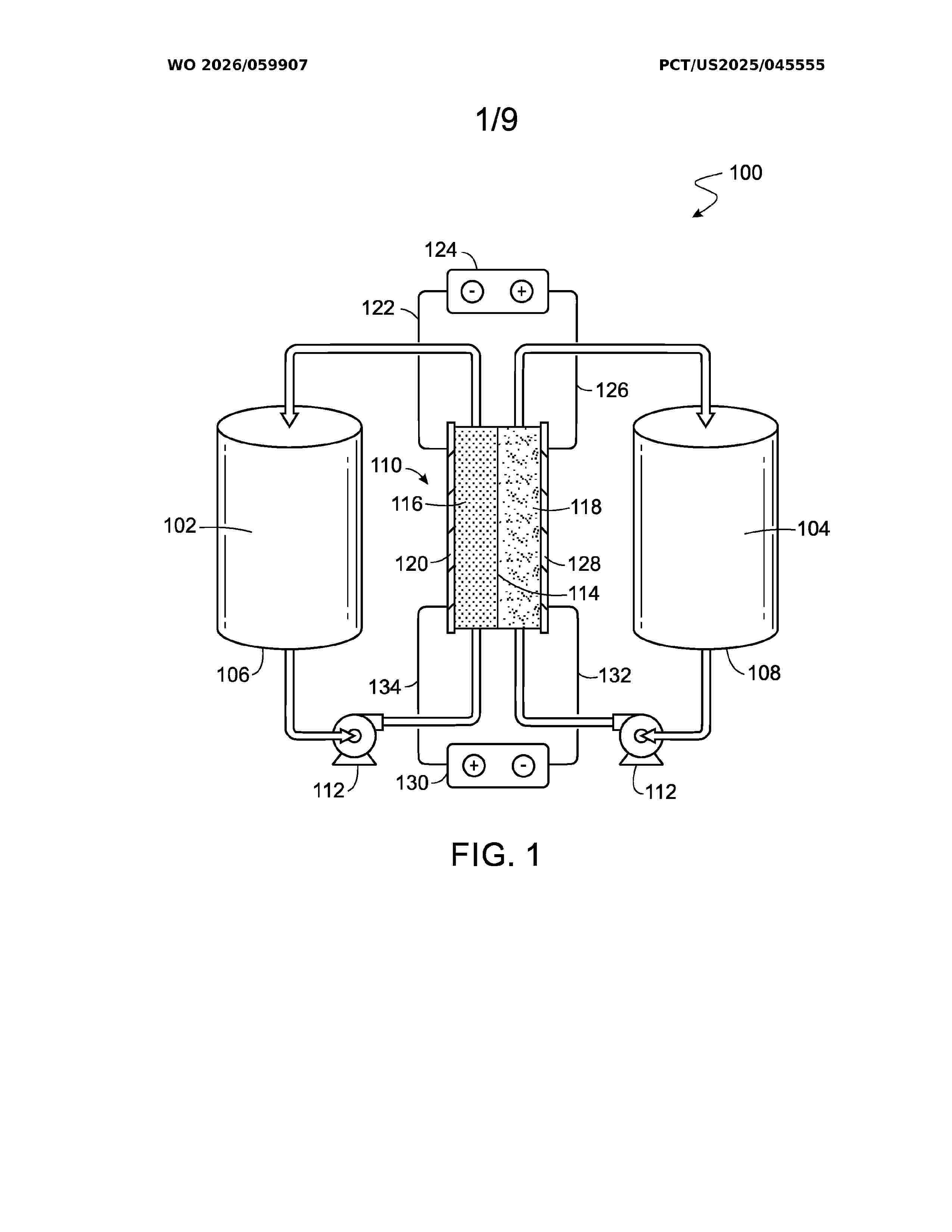
Resumen de: WO2026059907A1
A flow cell battery that includes at least one electrochemical cell. The electrochemical cell includes: an ion exchange membrane; a 1 mm to 4 mm thick anode; an anode current collector; a first bipolar plate disposed between the anode and the anode current collector; a first flow frame that defines first flow channels; a first tank including an anolyte that includes V4+ and V5+; a first pump to flow the anolyte from the first tank into the first flow channels; a 1 mm to 4 mm thick cathode; a cathode current collector; a second bipolar plate disposed between the cathode and the cathode current collector; a second flow frame that defines second flow channels; a second tank including a catholyte that includes V2+ and V3+; and a second pump to flow the catholyte from the second tank into the second flow channels.
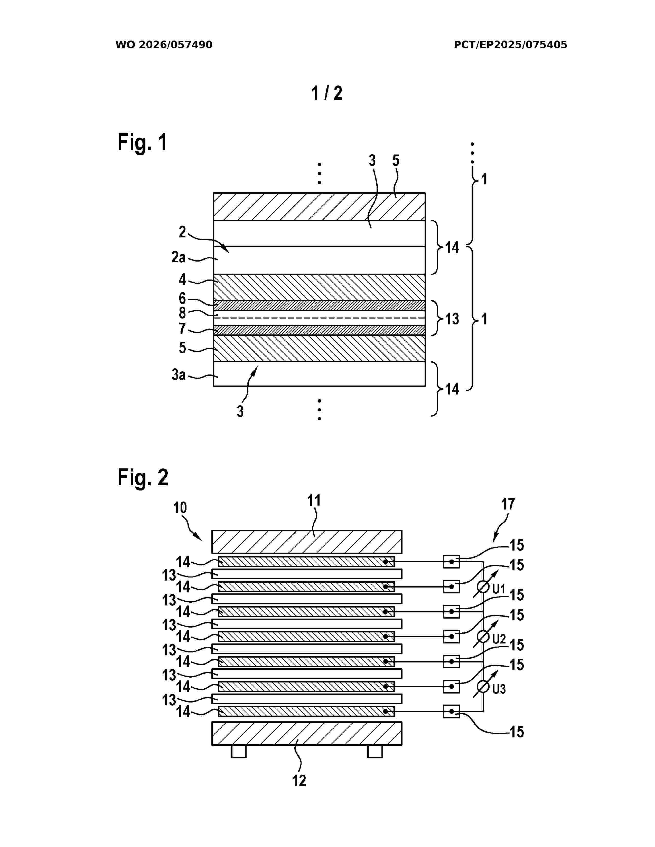
Resumen de: WO2026057490A1
The invention relates to a method for operating an electrochemical stack (10) which has a plurality of electrochemical cells (1) which each have an anode chamber (2) with an anode electrode (6) and a cathode chamber (3) with a cathode electrode (7), wherein the anode chamber (2) and the cathode chamber (3) are separated from one another by a semipermeable membrane (8). An electrical voltage occurs between the anode electrode (6) and the cathode electrode (7) during operation, wherein the electrochemical cells (1) are connected in series. A cell voltage monitoring unit (17) is connected to the electrochemical cells (1). The method is characterised by: - using the cell voltage monitoring system (17) to measure electrical voltages Ui of n series-connected electrochemical cells, n being greater than or equal to 2; - comparing the measured voltages Ui with a maximum voltage Uexp,n and a minimum voltage Umin,n, the maximum voltage Uexp,n being n times the maximum possible cell voltage of an individual electrochemical cell Uexp and Umin,n being (n-1) times the maximum possible cell voltage of an individual cell (1) plus a lower voltage limit ULimit, ULimit being the smallest cell voltage up to which an individual electrochemical cell (1) is to be operated; and, - outputting an error message if at least one of the measured voltages Ui is lower than Umin,n or higher than Uexp,n.
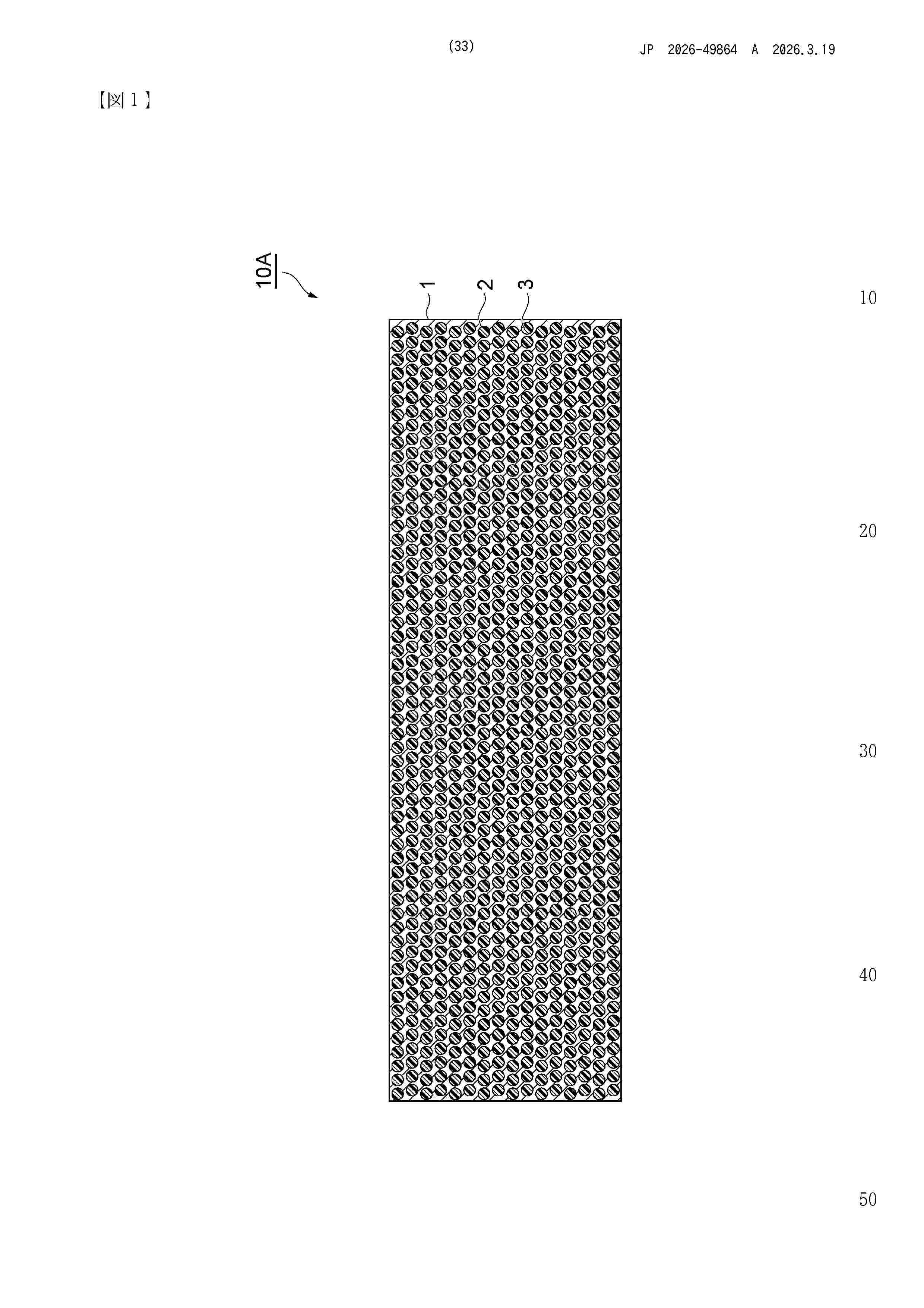
Resumen de: JP2026049864A
【課題】炭化水素系電解質膜の機械強度を向上させること。【解決手段】多孔質膜1と、多孔質膜1の細孔2に充填された炭化水素系電解質ポリマーと、を含み、多孔質膜1が、炭化水素系樹脂を含む材料で形成されており、バブルポイント法により測定される多孔質膜1の差分透過流量分布が、0.01~1μmの細孔径の範囲にピークを有する、電解質膜10A。【選択図】図1
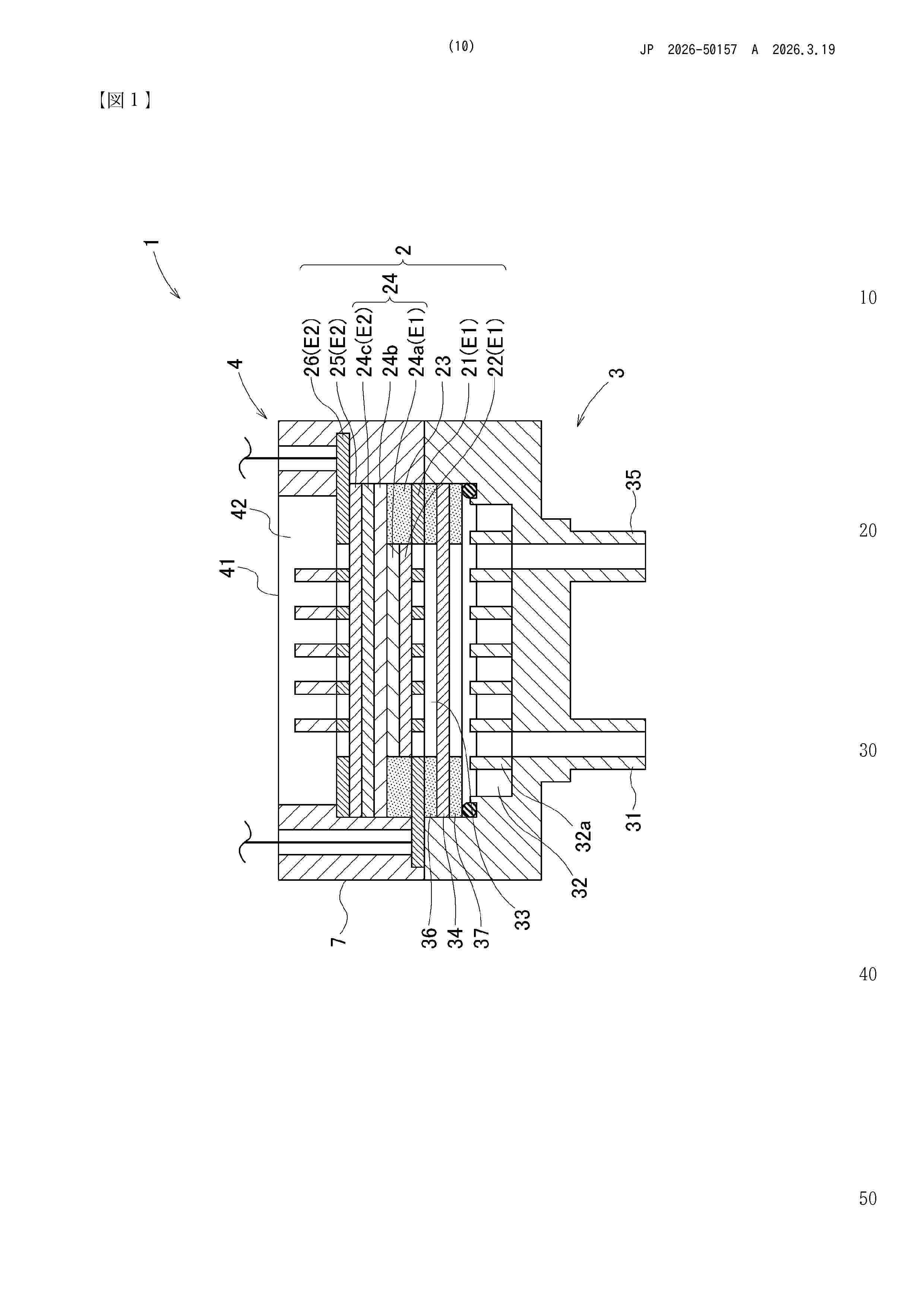
Resumen de: JP2026050157A
【課題】液体を測定対象とする場合であっても構成部材の劣化を抑制できる測定システムを実現する。【解決手段】水素極E1、空気極E2、および電解質24bを有する燃料電池セル2と、水素極E1に水素を供給する水素極セパレータ3と、燃料電池セル2において生じた電気エネルギーの量を測定する測定装置と、を備え、水素極セパレータ3が、測定対象の液体が撹拌される撹拌室32と、撹拌室32において液体から離脱した水素を水素極E1に案内する案内室33と、撹拌室32と案内室33との境界に配され、水素の透過を許容し液体の透過を許容しない分離膜34と、を有する。【選択図】図1
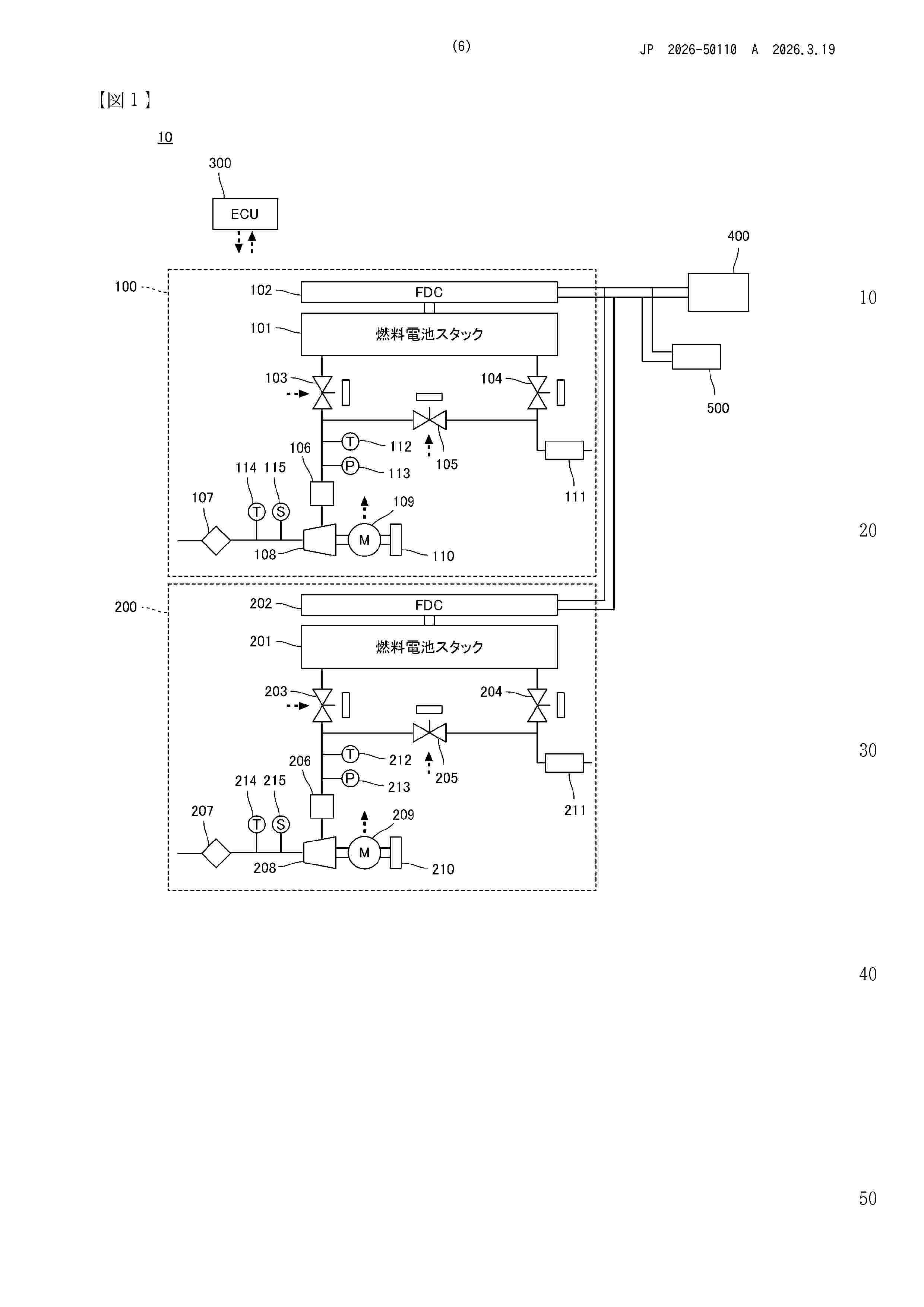
Resumen de: JP2026050110A
【課題】できる限り退避走行制御に移行することを防ぎつつ、再駆動制御を実行できる機会を確保できる燃料電池システムを提供する。【解決手段】燃料電池システムは、車両の駆動モータを駆動するための燃料電池システムであって、駆動モータへ電力を供給する複数の燃料電池モジュールを備え、駆動モータへ電力を供給する複数の燃料電池モジュールは、それぞれが燃料電池スタックと燃料電池スタックへ空気を供給するコンプレッサとを有し、いずれかのコンプレッサの脱調を検出した場合に、複数の燃料電池モジュールのうち脱調を検出していないコンプレッサを有する他の燃料電池モジュールに駆動モータへの電力供給量を増加させ、脱調を検出したコンプレッサの正常復帰制御を実行する制御部とを備える。【選択図】図1
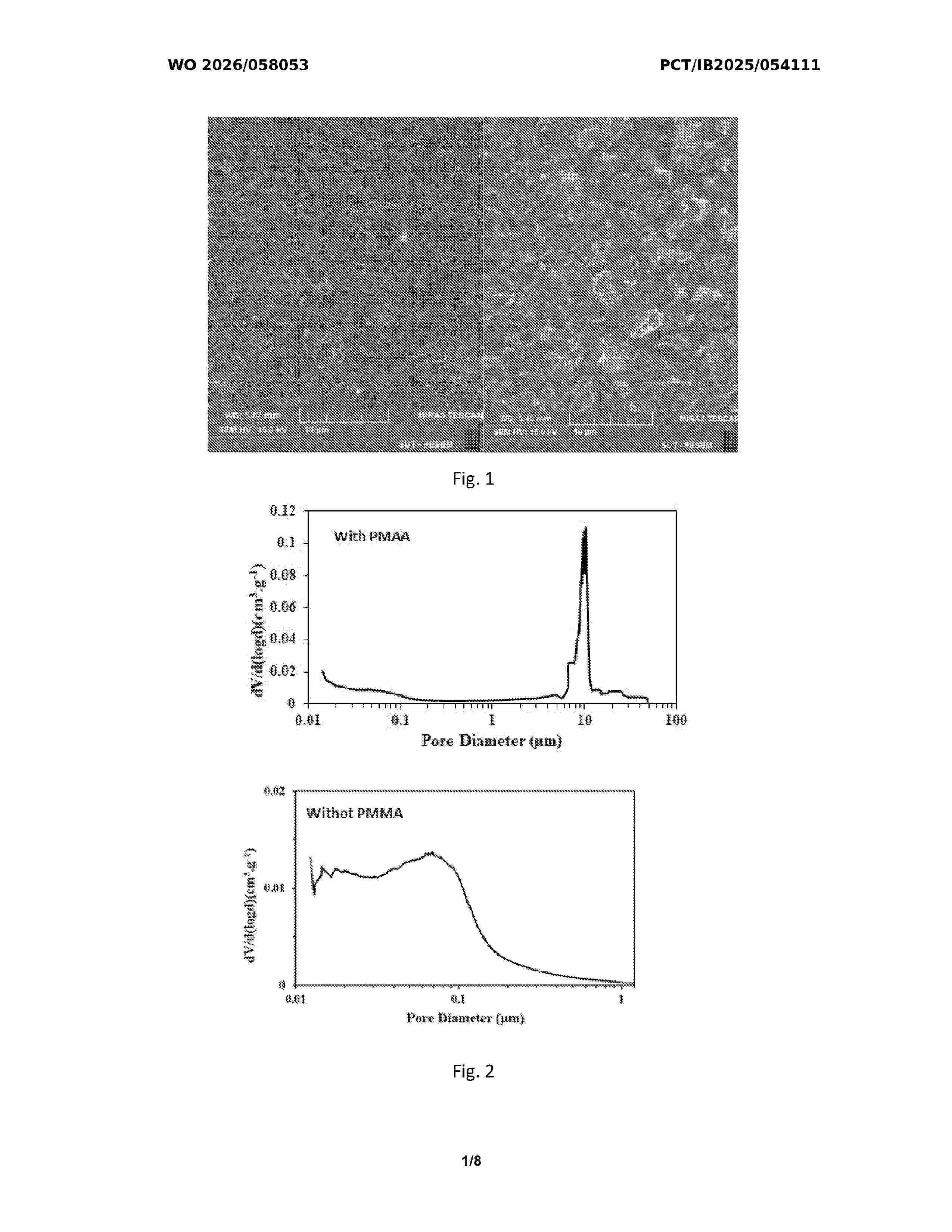
Resumen de: WO2026058053A1
A triple-layer gas diffusion layer (GDL) for proton exchange membrane (PEM) fuel cells comprises a macroporous substrate (MPS) made from multi-walled carbon nanotubes, polymethyl methacrylate as a pore-forming agent, and polytetrafluoroethylene as a binder, a first microporous layer (MPL) with carbon nanotubes and a hydrophobic binder, and a second MPL formed by electrochemical deposition of polyaniline. The MPS is fabricated by vacuum filtration of a suspension, followed by heat treatment to enhance porosity. The first MPL is deposited on the MPS, and the second MPL is added via a three-electrode system. This GDL is integrated into a membrane-electrode assembly with a treated membrane and platinum-on-carbon electrodes. The invention simplifies fuel cell design by managing water effectively across varying humidity levels, offering utility in energy applications.
Resumen de: WO2026053498A1
A fuel cell in which a plurality of fuel cell units are stacked and a porous body constituting a flow path for a cooling medium is arranged between the adjacent fuel cell units, wherein the porous body includes a plurality of through holes penetrating in the flowing direction of the cooling medium, and the plurality of through holes are arranged at intervals along the longitudinal direction of the porous body in a direction orthogonal to the flowing direction of the cooling medium.
Resumen de: DE102024126548A1
Die Erfindung betrifft eine Medientrennvorrichtung (10) für eine Brennstoffzelle mit einer Trägerplatte (1), auf deren erster Seite (1.1) ein erstes Medium und auf deren zweiter Seite (1.2) ein anderes Medium strömen kann, wobei auf einer Seite (1.1) der Trägerplatte (1) eine Abstandsvorrichtung zur beabstandeten Anordnung einer Trennschicht (6) vorgesehen ist, so dass zwischen der Trennschicht (6) und der Trägerplatte (1) das Medium in einem Kanal mit einer vordefinierten Höhe strömen kann, wobei die Abstandsvorrichtung als Einlegeblech (3) ausgebildet ist. Weiterhin betrifft die Erfindung Herstellungsverfahren zur Herstellung einer Medientrennvorrichtung (10) sowie eine Brennstoffzelle mit einer Medientrennvorrichtung (10).
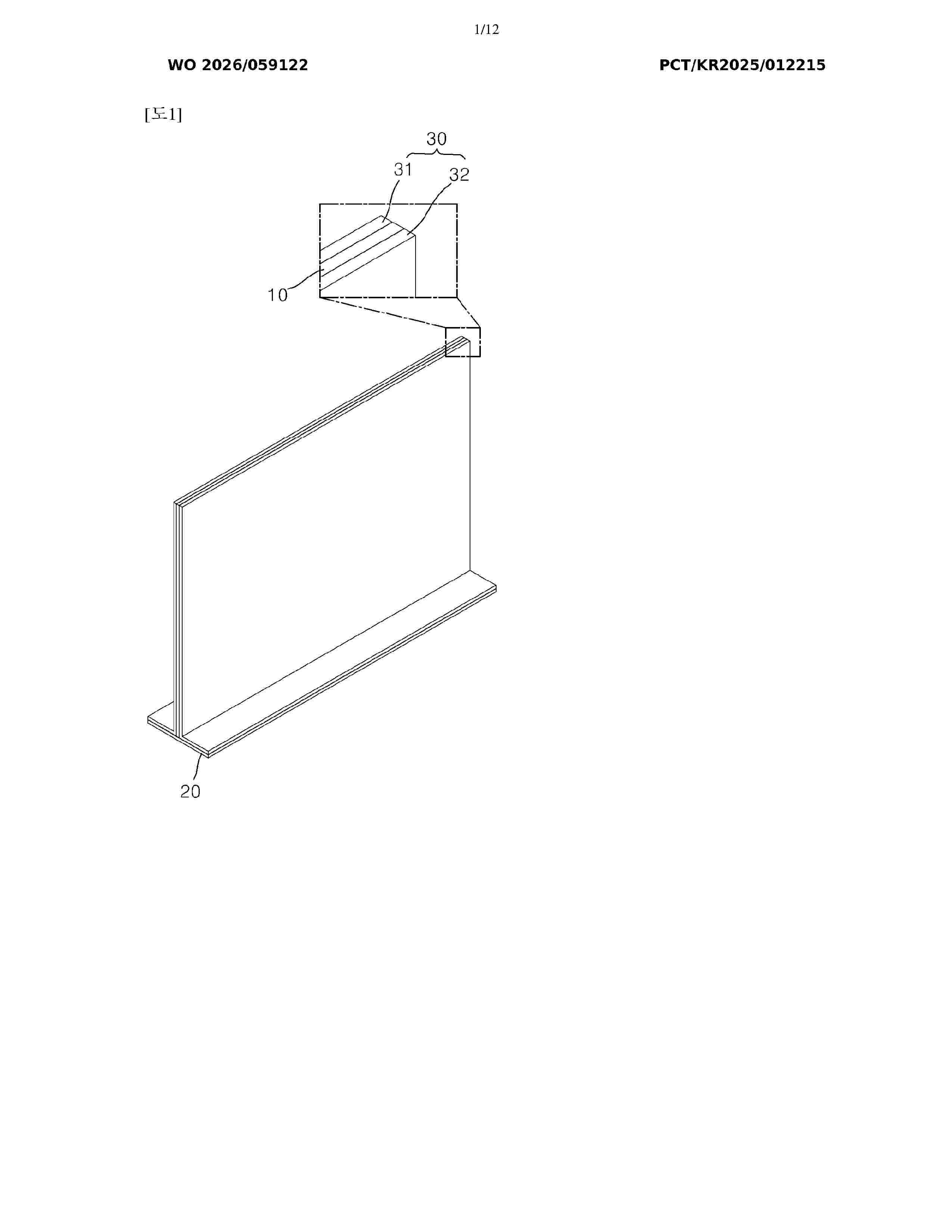
Resumen de: WO2026059122A1
A pulsating heat pipe module according to the present invention allows for the formation of complex flow paths, thereby maximizing heat dissipation. In addition, a press method is used in the present invention to manufacture the pulsating heat pipe module, which can reduce the processing time and cost compared to conventional methods such as etching, and thus the present invention enables mass production of the pulsating heat pipe module. Moreover, the pulsating heat pipe module according to the present invention comprises: a channel plate which has flow-path holes created by piercing a flat metal plate; a bottom plate which has flow-path grooves formed by shaping a flat metal plate and has slots into which the channel plate is inserted; and a cover plate formed by bending a flat metal plate to cover the outer surfaces of the channel plate and the bottom plate, and thus the present invention not only makes manufacturing easy and assembly simple, but also offers the advantage of increased heat transfer area because the working fluid flows through both the channel plate and the base plate.
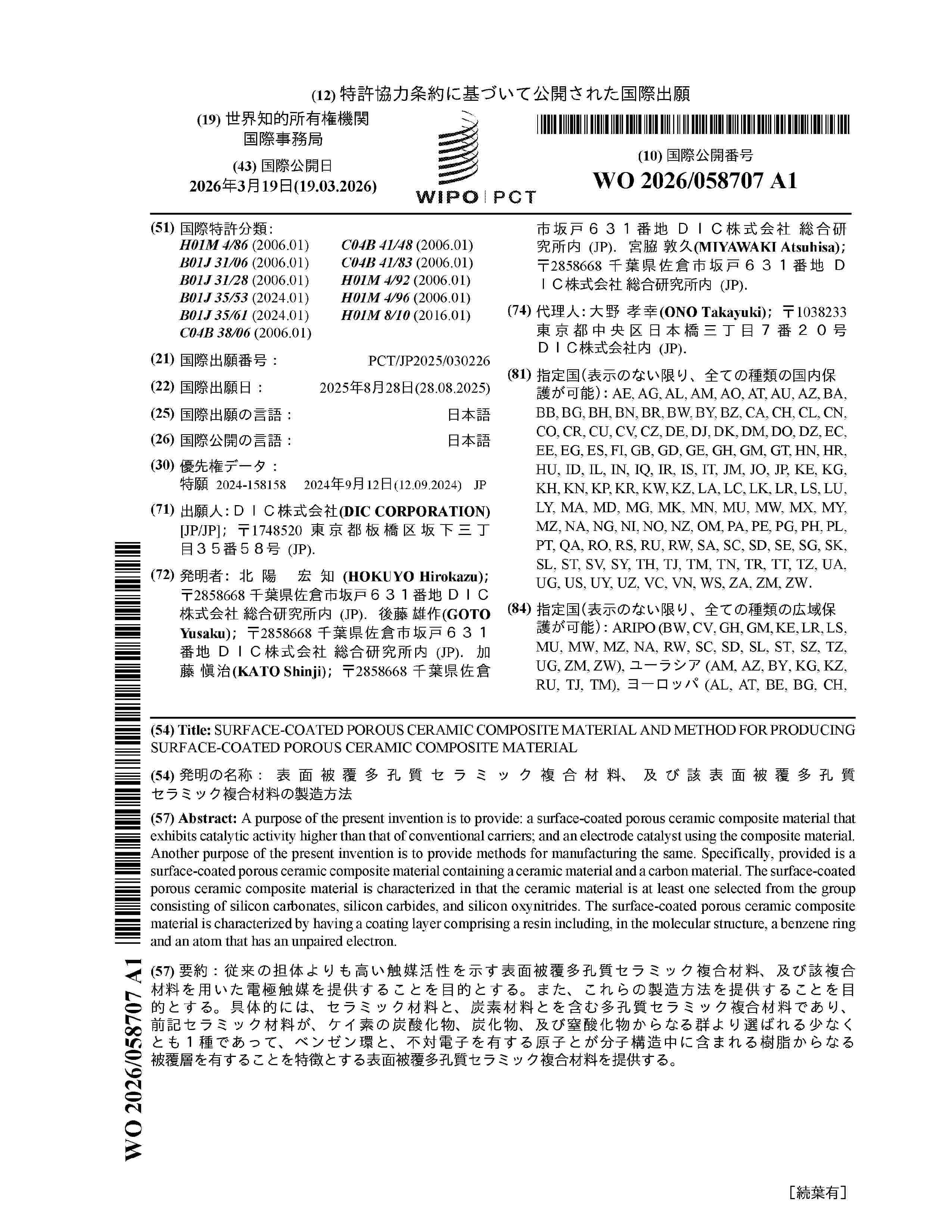
Resumen de: WO2026058707A1
A purpose of the present invention is to provide: a surface-coated porous ceramic composite material that exhibits catalytic activity higher than that of conventional carriers; and an electrode catalyst using the composite material. Another purpose of the present invention is to provide methods for manufacturing the same. Specifically, provided is a surface-coated porous ceramic composite material containing a ceramic material and a carbon material. The surface-coated porous ceramic composite material is characterized in that the ceramic material is at least one selected from the group consisting of silicon carbonates, silicon carbides, and silicon oxynitrides. The surface-coated porous ceramic composite material is characterized by having a coating layer comprising a resin including, in the molecular structure, a benzene ring and an atom that has an unpaired electron.
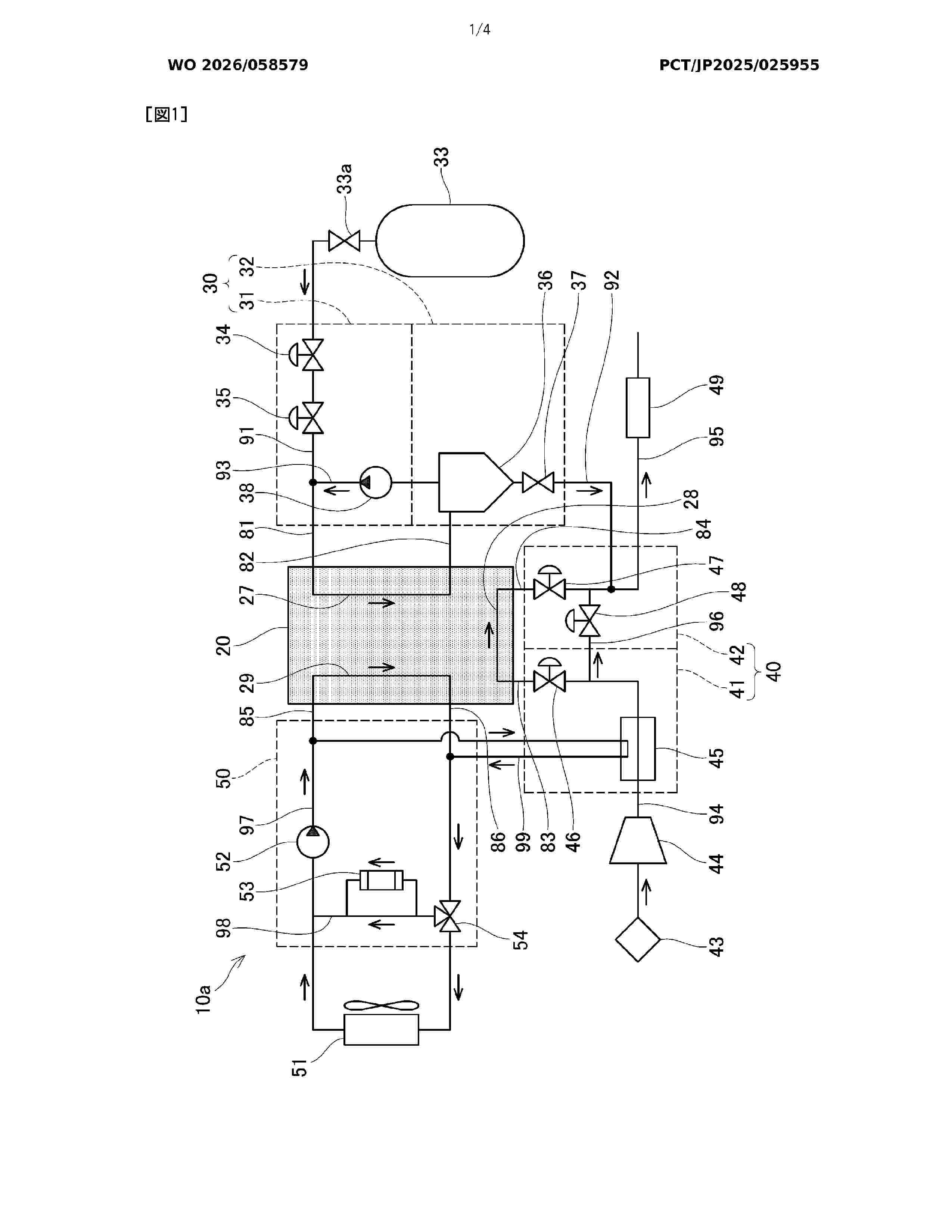
Resumen de: WO2026058579A1
The present invention simplifies the shape of a fuel cell module. Provided is a fuel cell module having a stack case that accommodates a fuel cell stack. The stack case has a first end surface, which is one end surface in a stacking direction of a plurality of fuel cells, and a second end surface, which is an end surface on the side opposite the first end surface in the stacking direction. A first pipe, which is at least one from among a group of pipes consisting of a fuel gas supply pipe, a fuel gas discharge pipe, an oxidant gas supply pipe, an oxidant gas discharge pipe, a coolant supply pipe, and a coolant discharge pipe, is connected to the first end surface, and a second pipe other than the first pipe among the group of pipes is connected to the second end surface.
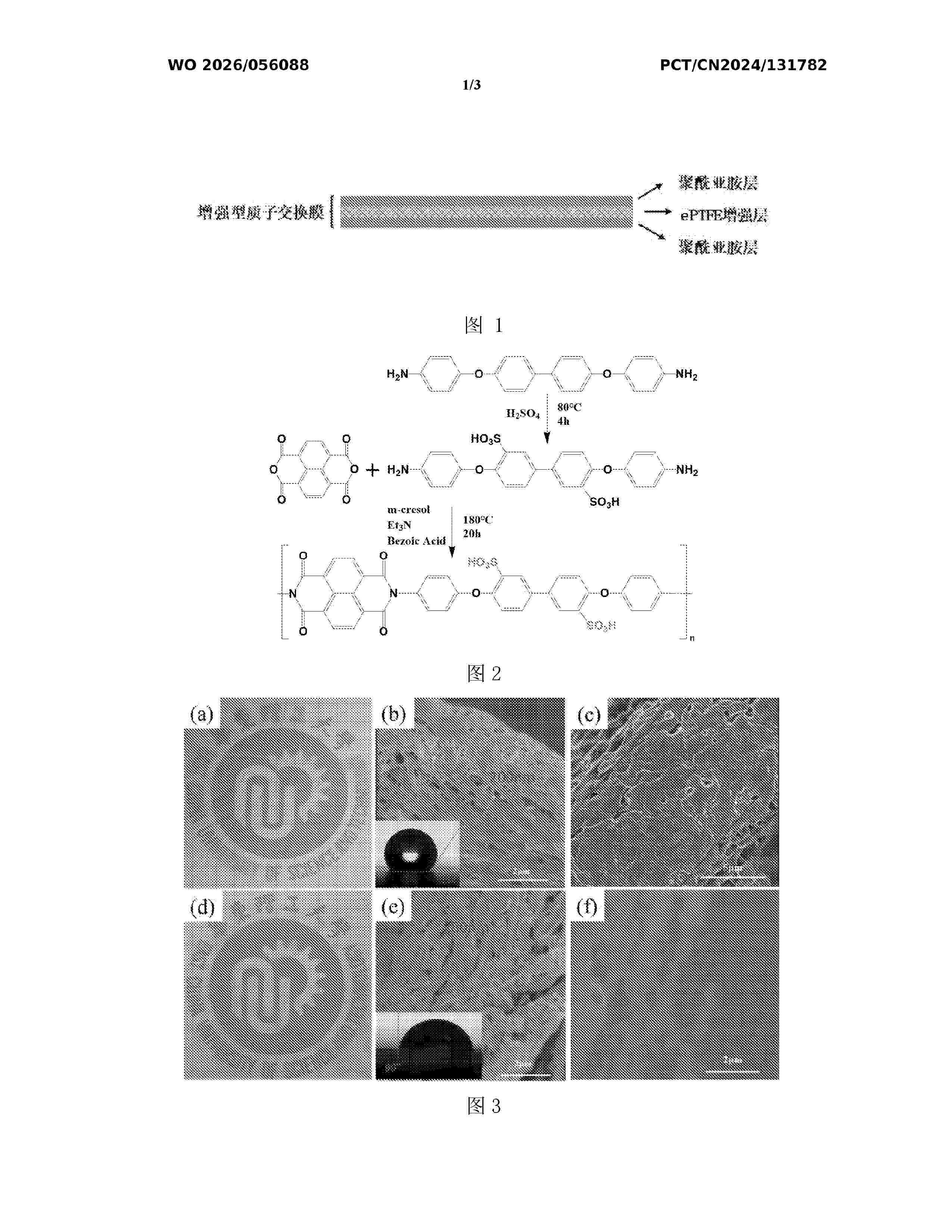
Resumen de: WO2026056088A1
A reinforced fully-sulfonated polyimide proton exchange membrane and a preparation method therefor. The proton exchange membrane comprises an ePTFE layer and polyimide layers, wherein two polyimide layers are provided; and the two polyimide layers are respectively formed on two sides of the ePTFE layer, and the pores of the ePTFE layer are filled with the polyimide layers. The preparation method for a proton exchange membrane comprises the following specific steps: S1: an ePTFE pretreatment; S2: preparation of fully-sulfonated polyimide; and S3: preparation of a composite membrane.
Resumen de: DE102024208863A1
Die Erfindung betrifft einen Redox-Flow-Stack (01). Dieser (01) umfasst ein linkes und ein rechtes Abschlusselement sowie mehrere zwischen diesen Abschlusselementen angeordnete Redox-Flow-Zellen (11). Jede Redox-Flow-Zelle (11) verfügt über eine linke und eine rechte Zellkammer (13, 14) mit entsprechenden Elektroden (17, 18) und Zellrahmen (15, 16) sowie eine Zellmembran (12), die die Zellkammern (13,14) trennt. Zudem sind Zelltrennelemente (19) zwischen benachbarten Zellkammern (13,14) vorhanden.Die Innovation liegt darin, dass alle Zellrahmen (15, 16) aus einem einstückigen, mittels Additive Manufacturing hergestellten Stackrahmen (02) bestehen.
Resumen de: DE102024208942A1
Die vorliegende Entwicklung betrifft ein Heizsystem (10) für ein Kraftfahrzeug (1) umfassend:- einen Fluidkreislauf (60), in welchem ein Wärmetauschermedium (39) zirkuliert,- einen katalytischen Konverter (40), welcher thermisch mit dem Fluidkreislauf (60) gekoppelt, über einen Einlass (41) mit einem Brennstoff (36) versorgbar und dazu ausgestaltet ist, den über den Einlass (41) zugeführten Brennstoff (36) unter Verwendung eines Katalysators (35) und unter Abgabe thermischer Energie an den Fluidkreislauf (60) in ein Reaktionsprodukt (38) umzuwandeln.
Resumen de: DE102024208738A1
Verfahren zum Betreiben eines Brennstoffzellensystems (100), wobei das Brennstoffzellensystem (100) mindestens einen Brennstoffzellenstack (101), einen Luftpfad (10), eine Abgasleitung (12) und eine Brennstoffleitung (20) mit Rezirkulationskreis (50) aufweist. Die Leistung eines ersten Brennstoffzellenstacks (101) wird erhöht, wobei eine durch das Brennstoffzellensystem (100) produzierte Menge an Strom erhöht wird, wenn die Feuchte der Membran des erstens Brennstoffzellenstacks (101) unter einer minimalen Feuchte liegt.
Resumen de: DE102024208868A1
Brennstoffzellensystem (100) mit mindestens einem Brennstoffzellenstack (11), einem Anodensystem (200), durch das ein Brennstoff strömt und einem Kühlkreis (400), durch den ein Kühlmittel rezirkuliert, wobei das Anodensystem (200) über ein Mittel zum Druckausgleich (27) mit dem Kühlkreis (400) verbunden ist.
Resumen de: DE102024208917A1
Die Erfindung betrifft ein Verfahren zum Betreiben eines Brennstoffzellensystems (100) mit mindestens einem Brennstoffzellenstack (101),wobei das Brennstoffzellensystem (100) ein Luftsystem (10) zur Versorgung des mindestens einen Brennstoffzellenstacks (101) mit einem sauerstoffhaltigen Reaktanten aufweist,wobei das Luftsystem (10) einen ersten Luftverdichter (11) und einen zweiten Luftverdichter (12) aufweist,wobei das Verfahren dazu dient, eine Multi-Ziel-Betriebsstrategie zum Betreiben des Brennstoffzellensystems (100) mittels Lastaufteilung zwischen dem ersten Luftverdichter (11) und dem zweiten Luftverdichter (12) bereitzustellen.Ferner betrifft die Erfindung ein Computerprogrammprodukt, eine Steuereinheit (ECU) sowie ein Brennstoffzellensystem (100).
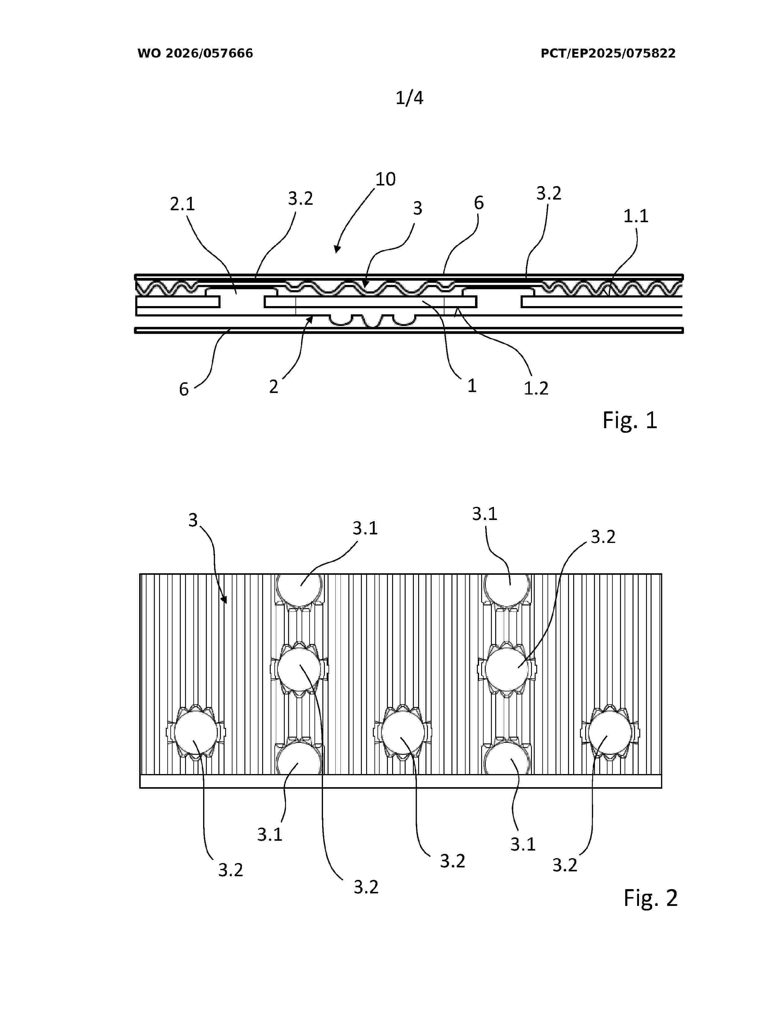
Resumen de: WO2026057666A2
The invention relates to a media separating device (10) for a fuel cell, comprising a carrier plate (1), on the first side (1.1) of which a first medium can flow and on the second side (1.2) of which another medium can flow, wherein a spacer device for arranging a separating layer (6) at a distance is provided on one side (1.1) of the carrier plate (1) such that the medium can flow in a channel having a predefined height between the separating layer (6) and the carrier plate (1), wherein the spacer device is designed as an insert plate (3). The invention further relates to a production method for producing a media separating device (10) and to a fuel cell having a media separating device (10).
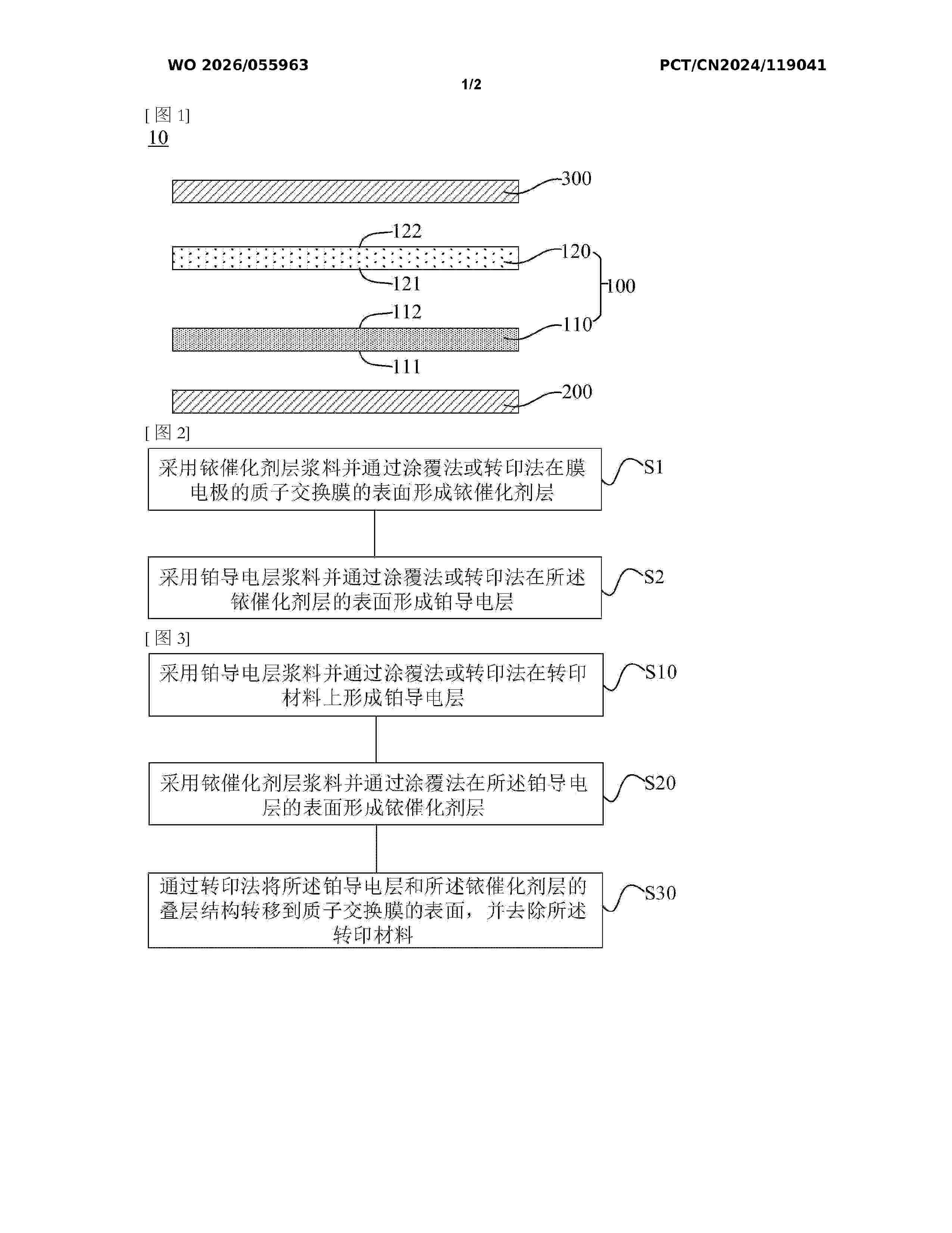
Resumen de: WO2026055963A1
Disclosed in the present application are an anode composite catalyst layer and a slurry thereof, a preparation method, and a membrane electrode. The anode composite catalyst layer is located between a proton exchange membrane and a gas diffusion layer of the membrane electrode, and comprises: an iridium catalyst layer, which has a first surface and a second surface which are opposite to each other, wherein the first surface faces the proton exchange membrane, and the second surface faces the gas diffusion layer, and the iridium catalyst layer comprises a first ionomer and an iridium catalyst dispersed in the first ionomer; and a platinum-conducting layer, which has a third surface and a fourth surface which are opposite to each other, wherein the third surface is in contact with the second surface of the iridium catalyst layer, and the fourth surface faces the gas diffusion layer, and the platinum-conducting layer comprises a second ionomer and platinum nano-particles which are dispersed in the second ionomer and have a particle size of 10-500 nm. The anode composite catalyst layer of the present application can endow the membrane electrode with a relatively low contact resistance and excellent stability.
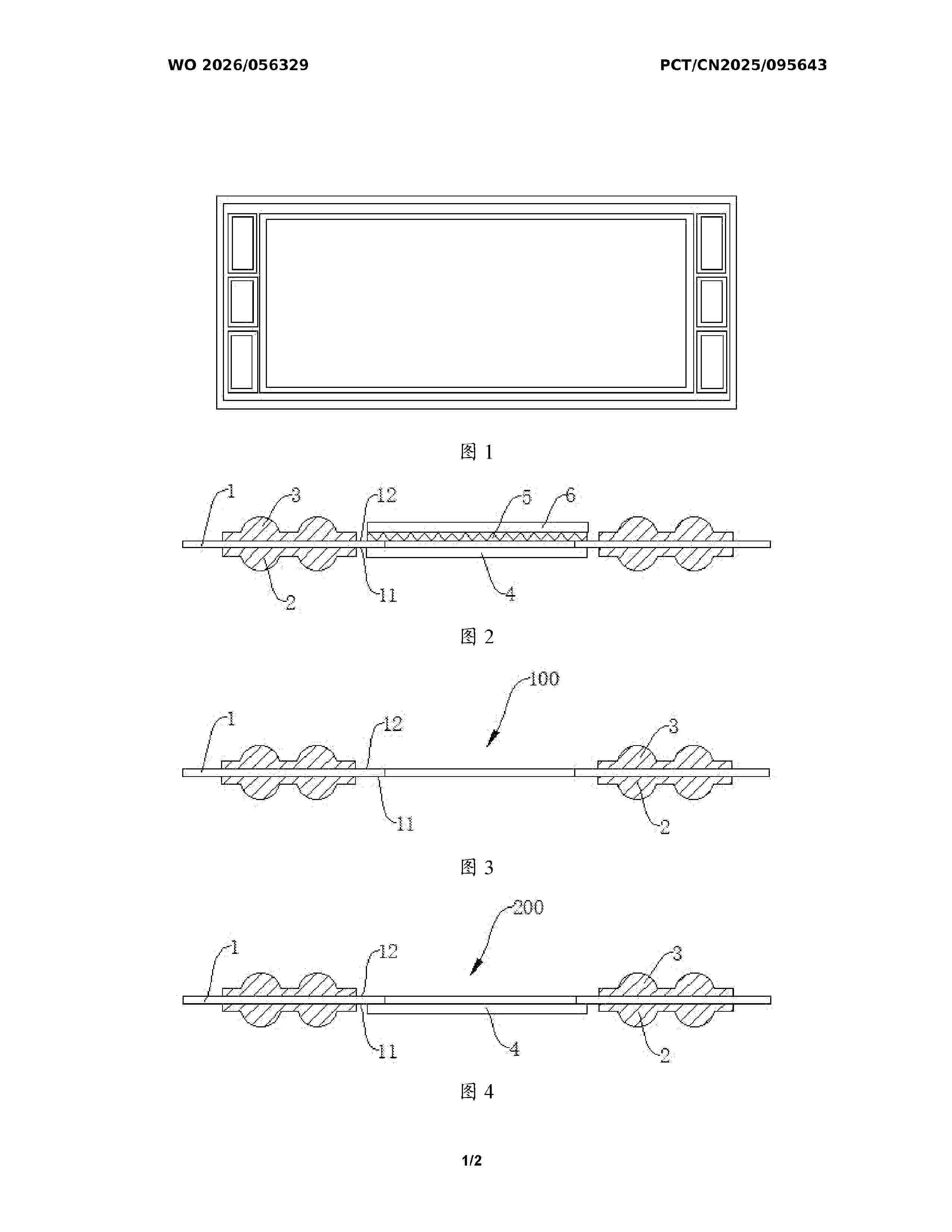
Resumen de: WO2026056329A1
The present invention relates to the field of membrane electrodes. Disclosed are a packaging method and packaging structure for a single-frame membrane electrode. A frame base material is separately connected to a first sealing member and a second sealing member to form a first assembly; the first assembly is connected to a first gas diffusion layer to form a second assembly; a catalyst coating CCM is connected to a second gas diffusion layer to form a third assembly; and the second assembly and the third assembly are assembled and aligned by means of a mold, and hot-pressed to form a single-frame membrane electrode having a sealing member. The present invention has the beneficial effects: a sealing element for stack assembly and a membrane electrode are assembled together in advance, so that the subsequent fuel cell stack assembly process is greatly simplified, the assembly precision is high, and the sealing element and a frame have good adhesion and are not easy to move, avoiding rework caused by misalignment of the sealing element during stack assembly, improving the stack assembly efficiency and yield, and reducing the costs.
Resumen de: DE102024126587A1
Die Erfindung betrifft eine Bipolarplatte (10) mit Hauptflächen (14, 16), einer ersten Mehrzahl von Erhebungen (18) und einer ersten Mehrzahl von Vertiefungen (20), einer zweiten Mehrzahl von Erhebungen und einer zweiten Mehrzahl von Vertiefungen, wobei eine Vertiefung (20) von einer Erhebung überlagert ist, wobei jede Erhebung (18) und jede Vertiefung (20) eine Länge (L), eine Breite (B) und eine Höhe aufweist, wobei jede Erhebung an ihrem in Höhenrichtung betrachteten freien Ende eine Toleranzausgleichseinrichtung aufweist, welche dazu eingerichtet ist, derart elastisch und/oder plastisch verformbar zu sein, dass sich die Höhe einer entsprechenden Erhebung reduziert, wenn eine Kraft auf das freie Ende der Erhebung einwirkt. Ferner betrifft die Erfindung einen Stack, umfassend zwei solcher Bipolarplatten.
Nº publicación: DE102024208974A1 19/03/2026
Solicitante:
BOSCH GMBH ROBERT [DE]
Robert Bosch Gesellschaft mit beschr\u00E4nkter Haftung
Resumen de: DE102024208974A1
Verfahren zum Betreiben eines Brennstoffzellensystems (100) mit mindestens einem Brennstoffzellenstack (11) und einem Anodensystem (200), wobei im Anodensystem (200) ein Drainventil (24) angeordnet ist, wobei folgende Schritte durchgeführt werden:i. Schalten des Drainventils (24), wobei das Schalten einen Übergang des Drainventils (24) von einer geöffneten Schaltposition in eine geschlossene Schaltposition und andersherum beschreibtii. Bestimmen eines Schaltmerkmals aus einer Strom-Kennlinie des Drainventils (24)iii. Ermitteln, ob Brennstoff während des Schaltens des Drainventils (24) durch das Drainventil (24) strömt
 BOPI
BOPI
 Sede Electrónica