Si deseas distinguir tus productos, servicios o ambos de los de otra empresa, es posible que necesites una marca o nombre comercial. Descubre qué son, en qué consiste su procedimiento de registro y qué implica.

Información sobre los plazos de presentación de solicitudes de transformación de marcas de la Unión Europea en marca nacional española. Más información


Si tienes un nuevo dispositivo, producto o procedimiento que resuelva un problema técnico o tenga una ventaja práctica, existen distintas formas de protegerlo en España y en otros países. Descubre cómo hacerlo.

¿Tu innovación reside en la estética, la ornamentación o la apariencia de tu producto? Protégela mediante un diseño industrial. Descubre qué derechos confiere el registro y cómo realizar la tramitación.

Las indicaciones geográficas protegen el nombre de un producto originario de una zona geográfica, a la cual le debe una determinada calidad, reputación u otra característica. Descubre qué son, en qué consiste su procedimiento de registro y qué beneficios conceden.

Las patentes publicadas en todo el mundo son una valiosa fuente de información científica, técnica y comercial.

Si eres emprendedor/a o una empresa y quieres potenciar y mejorar la rentabilidad de tu negocio protegiendo de forma adecuada los activos intangibles de tu organización, en este espacio encontrarás lo necesario.


 557
resultados
557
resultados
 Última actualización
02/04/2026 [06:49:00]
Última actualización
02/04/2026 [06:49:00]


 Resultados 400 a 425 de 557

Resumen de: CN121709663A
本发明公开了一种PEMFC纯氧转富氧阴极循环系统及富氧浓度控制方法。系统包括纯氧转富氧供给回路、阴极循环回路、富氧浓度控制单元。控制方法采用模型预测控制策略,以压力调节阀开度、循环泵转速和尾排阀开度为操纵变量,以氧浓度和压力为被控变量。通过状态观测器估计系统状态,基于状态空间模型进行多步预测,根据负载电流工作点自适应调用参数表中的权重与约束集,滚动求解有限时域优化问题获得最优控制序列并实施首个控制指令,周期滚动执行。本发明实现了对富氧浓度和阴极循环系统的自适应高精度控制,提升了燃料电池在密闭空间中的动态性能与运行安全性。

Resumen de: CN121709664A
本发明涉及钒电池技术领域,提供了一种通过反迁移恢复全钒液流电池性能的方法。本发明在全钒液流电池运行至发生容量衰减时,将正极电解液和负极电解液进行混堆,将混堆后的电解液分成两部分,将两部分电解液分别重新注入正极电解液和负极电解液的储罐内。本发明将正负极电解液进行混堆,混堆过程中,正极电解液中未放电的V5+通过自放电全部变成V4+,将混堆后的电解液重新注入正负极电解液的储罐内,从而确保正负极电解液中钒离子和价态平衡,实现恢复全钒液流电池的性能,恢复电池容量的目的。
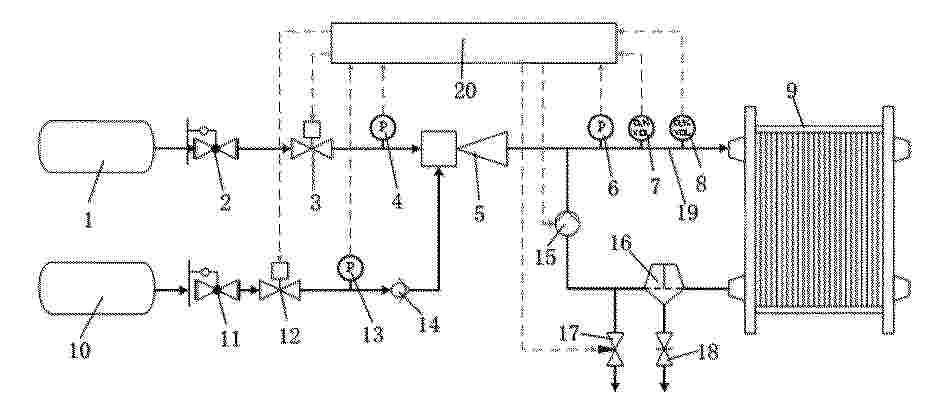
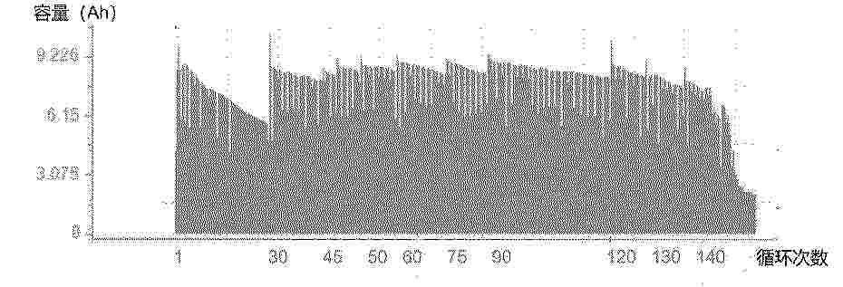
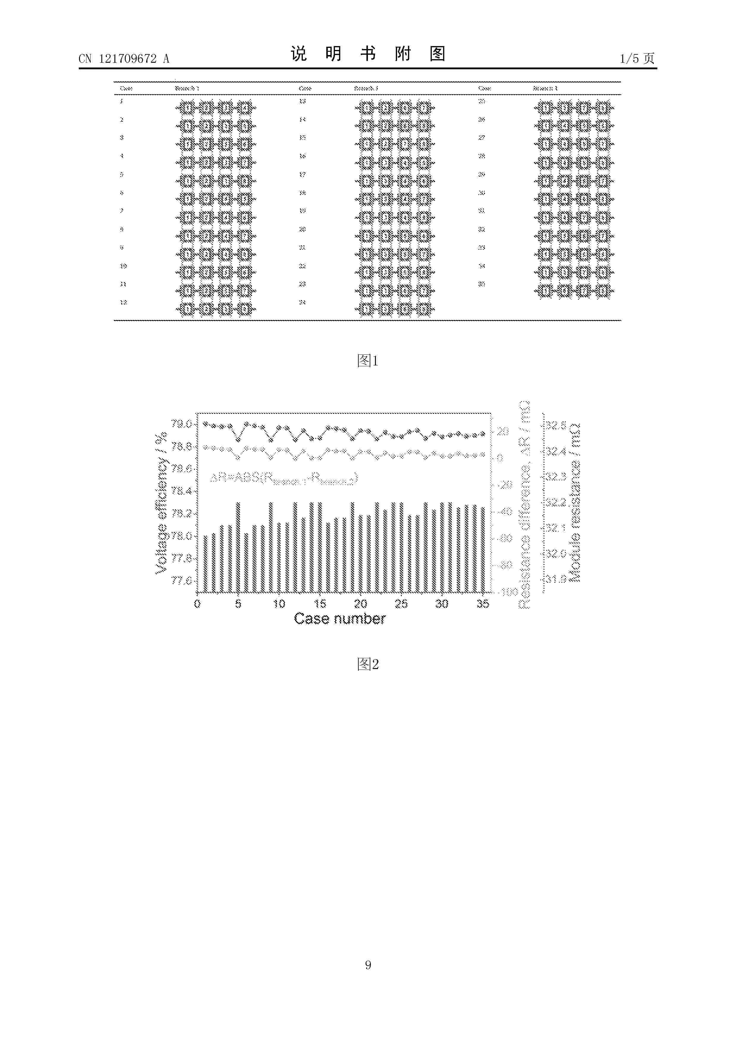
Resumen de: CN121709672A
本发明公开了一种水系有机液流电池及其应用,属于液流电池设计技术领域,针对电堆因材料和装配偏差导致的内阻不一致问题,通过优化电堆在模块中的排布方式,即采用将内阻相近的电堆布置于同一串联支路,并针对性能最差电堆实施流量的单独控制和优化,实现模块容量和效率的提升。通过建立动态模型,进行模拟仿真分析表明,将内阻相近的电堆布置于同一串联支路这一方法可显著提高模块的活性物质利用率,在牺牲较小系统效率的前提下大幅提升充电容量,对大型储能模块的高效、稳定运行具有重要意义。
Resumen de: CN121695886A
本发明属于碱性燃料电池及电解水制氢电催化技术领域,提供了一种用于碱性甲醇氧化与析氢的稀土氟化物复合催化剂,该催化剂以稀土氟化物修饰的过渡金属‑碳复合材料为载体,负载多组分金属活性中心,构建出NM/TM‑REFx/C结构的多元金属催化剂体系,其中NM为贵金属,TM为过渡金属,RE为稀土元素,各组分质量分数分别为:NM:1 wt%‑9 wt%,TM:2 wt%‑15 wt%,RE:0.5 wt%‑5 wt%;本发明通过稀土氟化物的电子调控与界面协同作用,解决了铂基催化剂在碱性甲醇氧化及析氢反应中贵金属用量大、抗CO中毒能力差及成本高等问题,适用于低温、高效、低能耗的碱性甲醇氧化及析氢过程。
Resumen de: CN121709668A
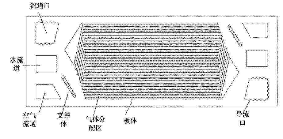
本申请涉及一种燃料电池系统、燃料电池阳极水控制方法和装置。所述系统包括引射器、燃料电池电堆和多层燃料电池双极板;每层燃料电池双极板至少包括流道口,流道口上包括多个导流口;多层燃料电池双极板的流道口形成公共流道,导流口形成导流槽,公共流道与氢气歧管连接;其中:引射器,用于将公共流道的输出口的回流氢气导入氢气歧管的输入口,以使回流氢气与燃料电池系统的氢气进入端口的新氢气进行混合得到混合氢气;氢气歧管,用于在混合氢气的吹扫作用下,将回流氢气与新氢气混合产生的液态水,引向燃料电池系统的导流槽和公共流道,以及通过导流槽和公共流道导入隔离结构中。采用本系统能够提高燃料电池的安全性的。
Resumen de: CN121709670A
本发明涉及钒电池技术领域,提供了一种钒电池电解液及其制备方法,本发明将五氧化二钒、浓硫酸和水混合后加热,然后加入亚酸酯,之后依次进行进行煮沸、冷却和过滤,得到所述钒电池电解液;五氧化二钒和浓硫酸的质量比为1:(1.3~1.5);五氧化二钒和亚酸酯的质量比为1:(1.1~1.3);所述亚酸酯包括以下质量分数的组分:草酸50~51%,亚硫酸钠4~5%,醋酸乙酯45~46%。和传统钒电池电解液相比,本发明使用的浓硫酸和草酸用量大大减少,所得电解液的呈弱酸性,腐蚀性和危险性大大降低,且充放电过程中不易析出,不易堵膜。综上所述,本发明提供的钒电池电解液和传统电解液相比,更加安全、环保、高效。
Resumen de: CN121709660A
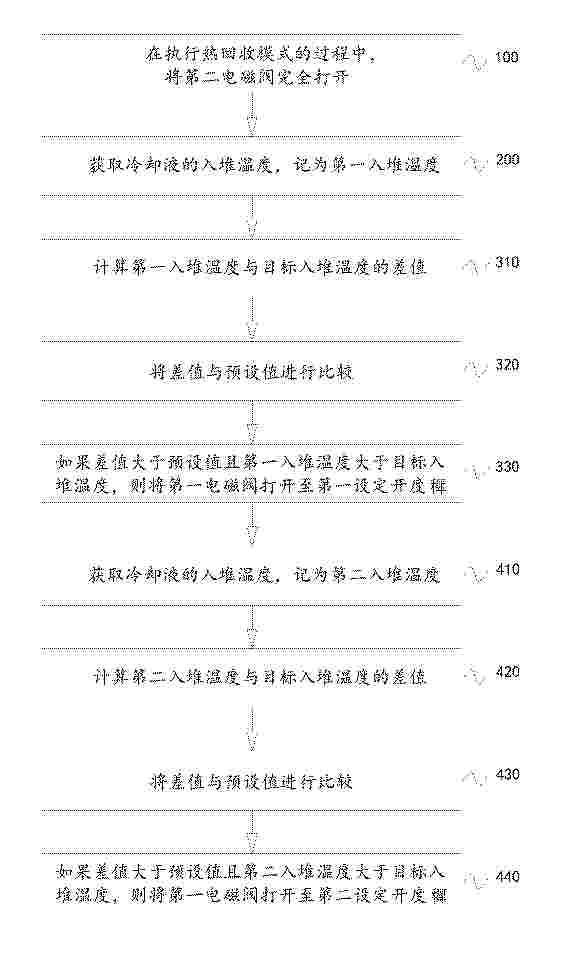
本发明涉及燃料电池技术领域,具体提供一种燃料电池余热回收系统的控制方法及余热回收系统。具体地,本发明的燃料电池余热回收系统包括燃料电池、散热器、换热器和蓄热水箱,散热器的两端和换热器的两端均与燃料电池的冷却液出口和冷却液进口连通,燃料电池与散热器和换热器之间分别设有第一电磁阀和第二电磁阀;换热器与蓄热水箱连通,控制方法包括:在执行热回收模式的过程中,将第二电磁阀完全打开;获取冷却液的入堆温度;根据入堆温度,选择性地打开第一电磁阀。当需要通过散热器对冷却液进行降温时,能够及时的打开第一电磁阀,以避免因为冷却液的温度过高而导致燃料电池的电堆温度偏高,有利于保证燃料电池的电堆温度的稳定性。
Resumen de: CN121709659A
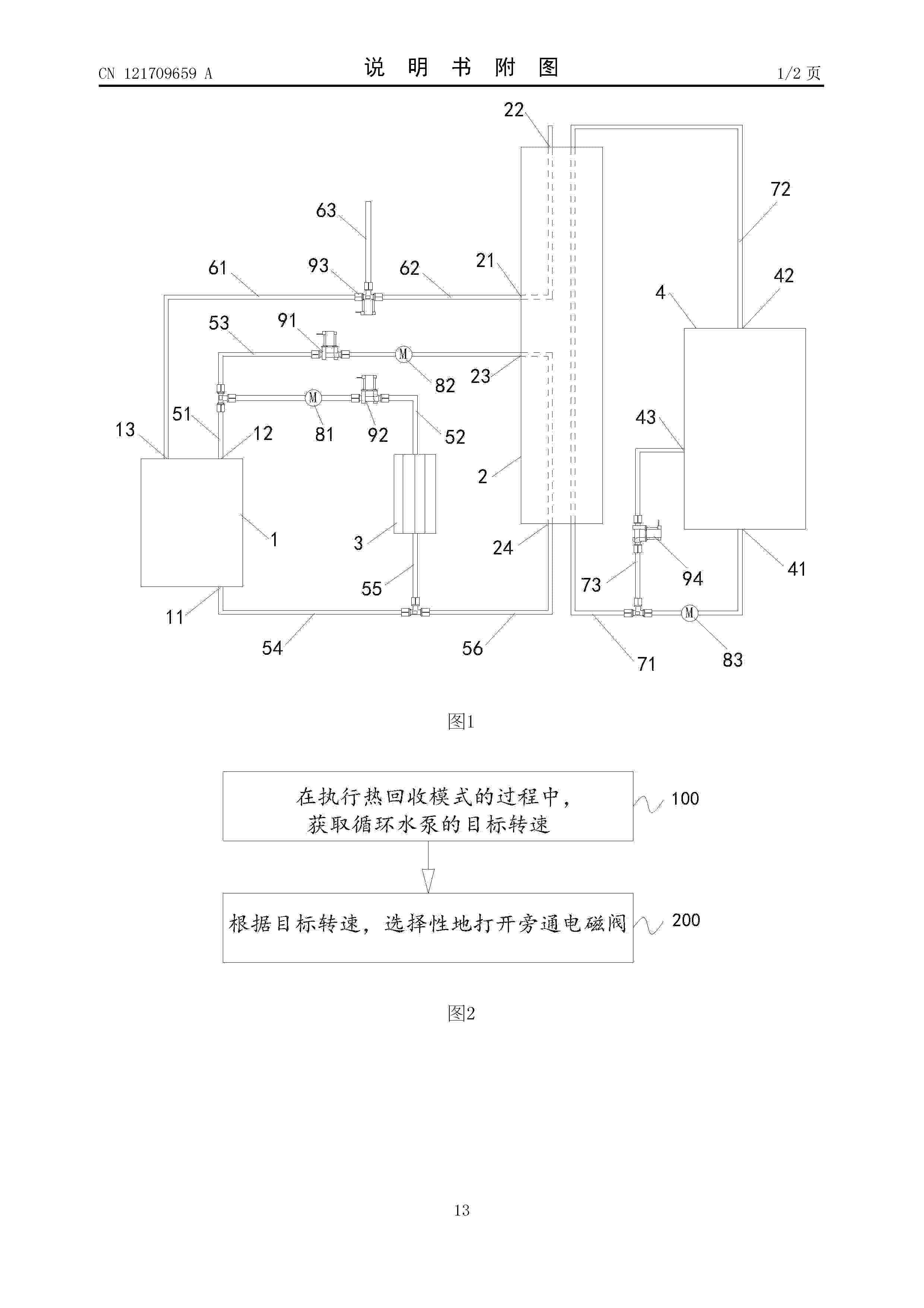
本发明涉及燃料电池技术领域,具体提供一种燃料电池余热回收系统的控制方法及余热回收系统。具体地,本发明的燃料电池余热回收系统包括燃料电池、换热器、蓄热水箱及与换热器并联的旁通水管,换热器的两端与燃料电池的冷却液出口和冷却液进口连通,蓄热水箱通过第一循环管和第二循环管与换热器连通,第一循环管上设有水泵,旁通水管上设有旁通电磁阀,控制方法包括:获取水泵的目标转速;根据目标转速,选择性地打开旁通电磁阀。通过目标转速来判断是否需要打开旁通电磁阀,以便水泵的实际转速无法达到目标转速时,及时地打开旁通电磁阀,从效果上等同于降低水泵的转速,有利于保证冷却液的入堆温度在设计的温度范围内,从而避免电堆温度偏低。
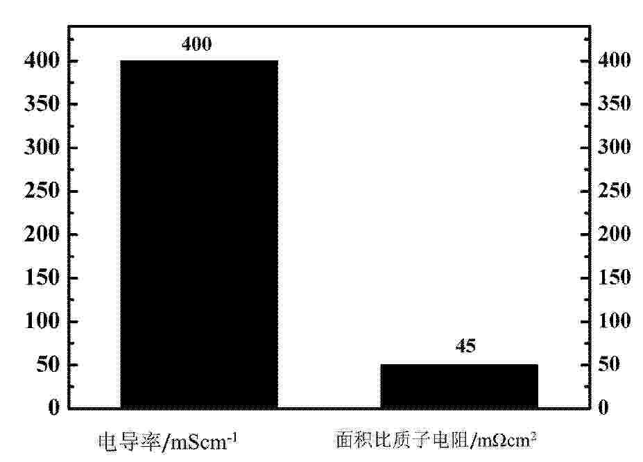
Resumen de: CN121709651A
本申请涉及质子交换膜技术领域,公开了一种以酸掺杂吡啶型侧链的新型纳米复合膜,所述复合膜包括:一种双功能含吡啶侧基聚芳醚酮酮聚合物;六方氮化硼纳米片(h‑BN);磷酸,所述聚合物通过含吡啶侧基的单体(2,6‑二(4‑羟基苯基)吡啶)和含乙烯基侧链的单体(4,4'‑(1,2‑乙烯基)二苯酚)等共聚得到,该复合膜通过将聚合物与h‑BN制成基膜,随后进行磷酸溶液掺杂,最后进行140℃至180℃的热处理以引发乙烯基交联。本发明利用吡啶基团对磷酸的酸碱吸附作用,与热交联网络对磷酸的物理锁定作用,构建了双重掺杂剂保留机制,纳米片则提供了物理阻隔,该复合膜兼具高质子传导率、低钒离子渗透率和优异的长期稳定性。
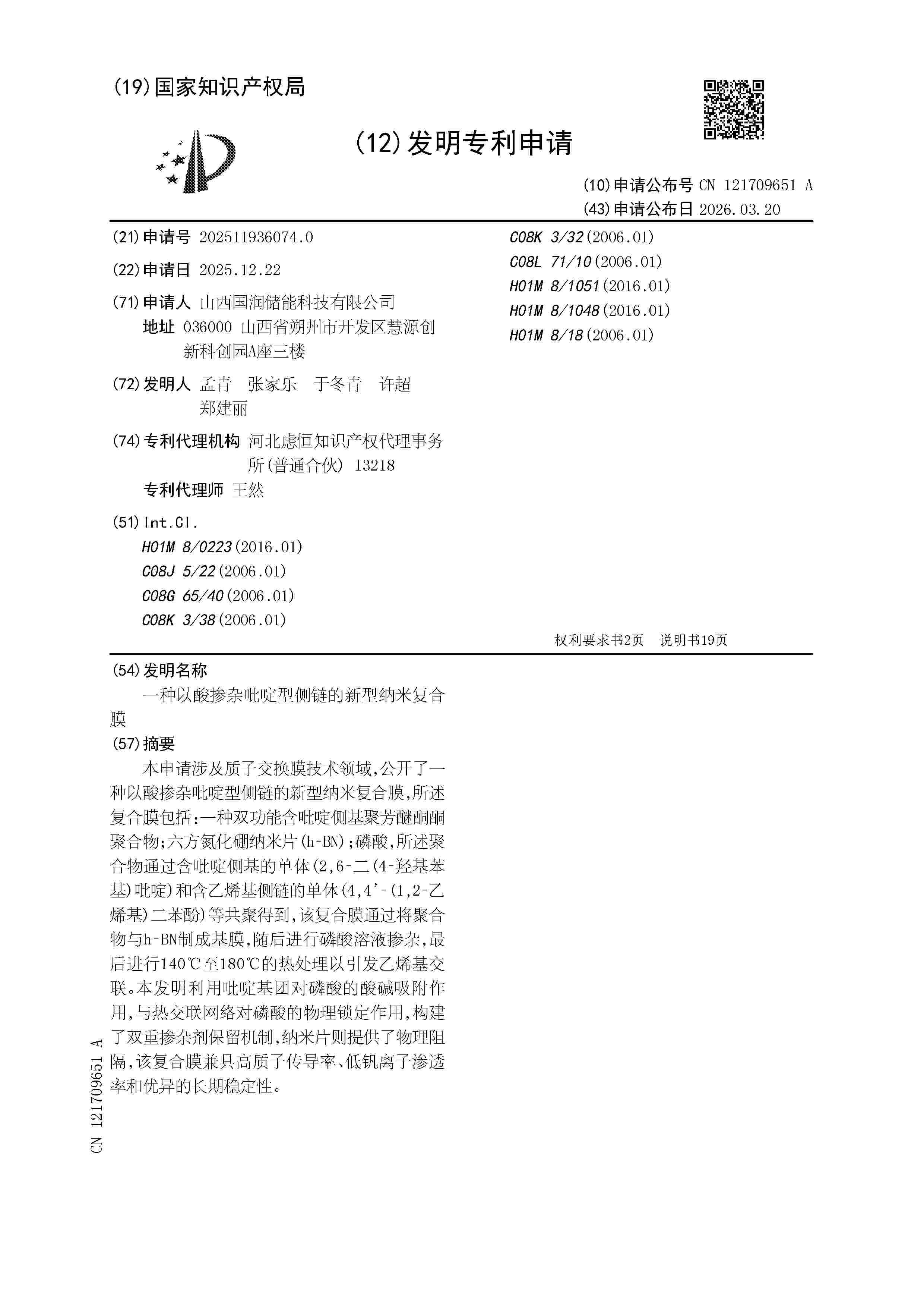
Resumen de: CN121709666A
本发明公开了一种燃料电池用在线EIS检测系统及在线EIS检测方法,所述系统包括DC‑DC变换器、DC‑DC控制模块、EIS测量模块、燃料电池及负载;DC‑DC变换器、燃料电池与负载构成主回路;DC‑DC变换器还设有一控制端;DC‑DC控制模块与DC‑DC变换器连接,用于在控制DC‑DC变换器运行时,向DC‑DC变换器的控制端发送注入特征频率的扰动信号的驱动控制信号,激励燃料电池产生响应信号;DC‑DC控制模块还设有一信号采集端,信号采集端与燃料电池及DC‑DC变换器连接,用于采集所述燃料电池的响应信号;EIS测量模块的信号输入端复用DC‑DC控制模块的信号采集端;EIS测量模块基于采集的所述响应信号,计算所述燃料电池在所述特征频率下的阻抗。本发明实现了在燃料电池的正常工作状态下实时、高效的EIS检测。
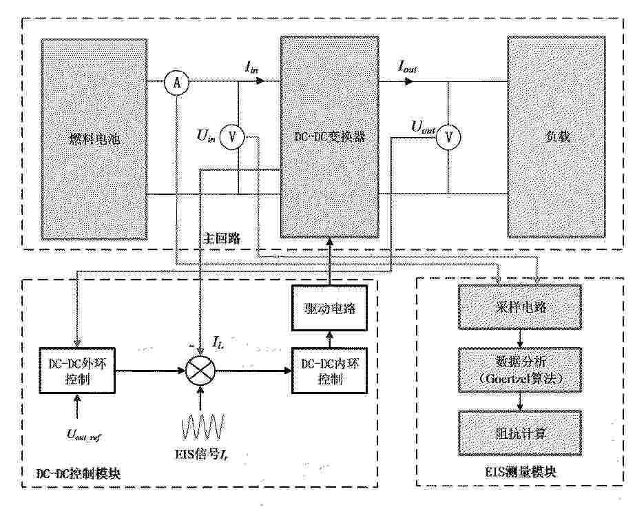
Resumen de: CN121702655A
本申请实施例涉及气密性检测技术领域,尤其涉及一种燃料电池电堆气密性测试方法及检测装置,其中,方法包括通过检测装置向所述燃料电池电堆的目标测试腔体内充入设定压力的测试气体,同时向检测装置内部的参考容积腔体内充入相同压力的相同气体,将所述目标测试腔体和所述参考容积腔体隔离,并监测压力差;在所述目标测试腔体和所述参考容积腔体不存在压力波动后,基于所述预设周期内压力差的变化值、目标测试腔体的容积、测试时间以及气体性质参数,确定燃料电池电堆的气密性是否合格;本申请实施例通过建立等压平衡的差压比较系统并监测压差变化,实现了对燃料电池电堆气密性的精确、高效、自动化检测。
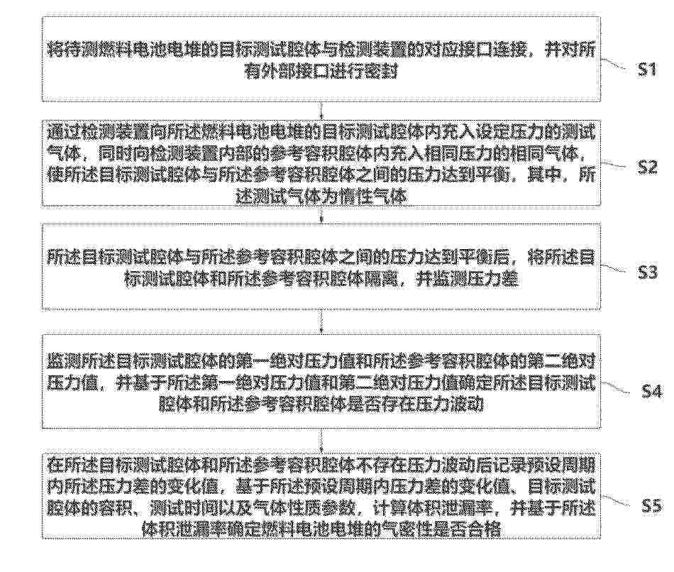
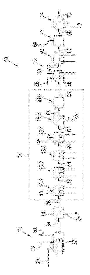
Resumen de: CN121709669A
熔盐供热型甲醇重整燃料电池储能装置及方法,明属于综合能源存储技术领域。熔盐储能系统采用复合相变储热熔盐,其储热密度与热稳定性显著提升;催化重整器采用锯齿螺旋管束式结构以强化传热;燃料电池采用仿生分形流道双极板以提升气体分布均匀性与发电效率。本发明利用熔盐储能系统储存的绿色热能,为甲醇重整制氢系统提供稳定、零碳排的反应热;通过废热回收系统将燃料电池发电系统产生的高温尾气及反应废热进行回收,并回馈至熔盐系统或用于催化重整和蒸汽发生,构建了系统内部的热量闭环。方法部分包括利用廉价能源加热熔盐进行储能,以及利用熔盐热驱动甲醇重整制氢、进而通过燃料电池发电的供能过程。
Resumen de: CN121710740A
本发明涉及热电化学温差发电技术领域,具体为一种基于多溶剂梯级蒸发‑冷凝的电化学热电转化方法及装置,解决了传统TREC系统的电解液因普遍采用单一溶剂体系,受限于溶剂沸点特性,当热源超溶剂沸点时无法稳定工作,同时局限于单一温度水平的热能利用,缺乏有效的梯级利用机制,无法适配热量连续温度下的分布,热量在收集与转换过程中存在明显的能量耗散的问题,基于多溶剂梯级蒸发‑冷凝的电化学热电转化装置,包括多级串联TREC单元、多级蒸汽换热单元、多级蒸汽流通单元及多级溶剂循环复用单元。本发明以双溶剂体系适配中高温工况,梯级传热提升热能回收效率,闭环循环降低溶剂损耗,模块化结构增强场景适配性,在低品位能源利用领域应用前景良好。
Resumen de: CN121709662A
本发明涉及燃料电池技术领域,具体涉及一种用于UUV的氢氧燃料电池阴极闭式循环多模式协同调控系统,包括:氮气供应模块、氧气供应模块、混合模块、气体循环与水热管理模块、检测模块以及控制模块;控制模块用于在电堆的实时温度小于预设的温度阈值时,控制电堆进入预热模式;用于在负载变化率大于阈值时,控制电堆进入动态负载响应模式;用于在单电池电压异常波动时控制系统进入水管理辅助模式;用于在阴极氢气浓度大于氢浓度安全阈值时,控制系统进入安全纯化模式。本发明能够快速、准确地跟踪负载变化,并及时调控电堆氧气分压,避免系统性能的剧烈波动。
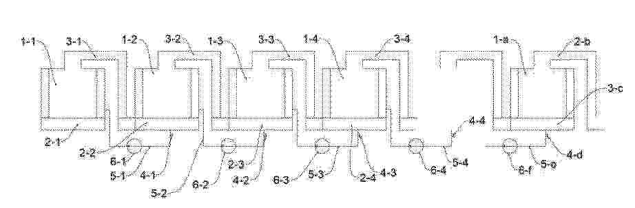
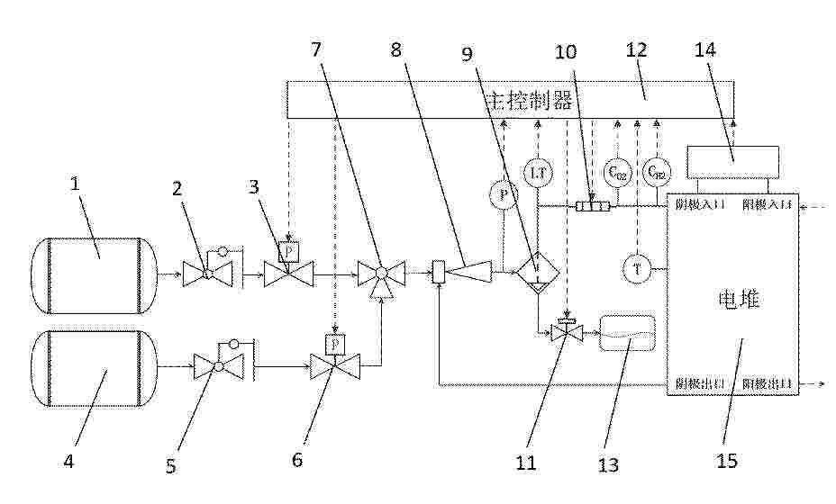
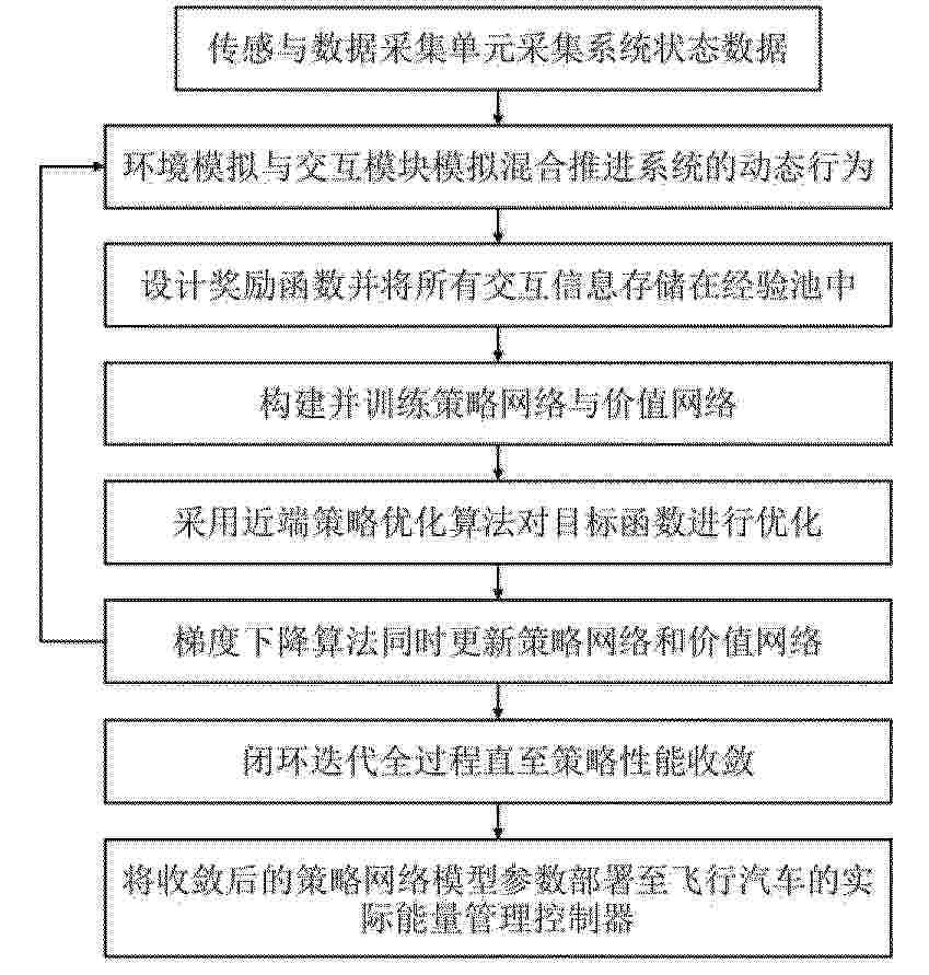
Resumen de: CN121697510A
本发明公开了一种燃料电池混合推进系统及其功率波动‑消耗协同优化方法,系统包括:燃料电池发电单元、锂离子电池单元、电力驱动单元、传感与数据采集单元以及能量管理控制器;基于近端策略优化,通过构建以系统状态、工况信息为输入,以动力源功率分配指令为输出的智能体,并设计融合了总能耗惩罚与功率波动惩罚的奖励函数,驱动智能体在连续动作空间中学习最优能源管理策略。本发明能在满足动态功率需求与安全约束的前提下,抑制锂离子电池功率的频繁剧烈波动,延长电池寿命、保障系统安全的同时最小化整体氢燃料消耗,实现长期运行经济性与系统输出平稳性的协同最优,以实现混合推进系统在动态环境下的高效、平顺、长寿命运行。
Resumen de: CN121709645A
本发明属于膜电极技术领域,涉及一种抗铂毒害的膜电极催化层浆料及其制备方法和应用。该膜电极催化层浆料包含以下组分:铂基催化剂、离聚物、主分散溶剂,以及至少一种多元醇。该膜电极催化层浆料中的多元醇能解决因传统低沸点溶剂快速挥发导致的催化层结构缺陷问题,且能有效抑制和降低离聚物磺酸基团对铂基催化剂的毒害效应,从而提升膜电极的综合性能。
Resumen de: CN121709638A
本发明公开一种宽湿度工况自适应的膜电极及其制备方法,包括质子交换膜,质子交换膜的两侧分别设有阴极催化层和阳极催化层,阴极催化层与阳极催化层的外侧均设有气体扩散层;阴极催化层由至少两层功能梯度层组成,功能梯度层包括催化剂、离聚物、溶剂、水传输通道组分和气体传输通道组分;功能梯度层在从质子交换膜向气体扩散层的方向上,水传输通道组分质量比例连续递减,气体传输通道组分质量比例连续递增;水传输通道组分为孔径分布在2~20 nm的亲水耐酸纳米多孔碳材料,气体传输通道组分为孔径分布在20~120 nm的疏水耐酸纳米多孔碳材料。通过亲水多孔材料与疏水多孔材料协同调控的催化层结构,提升电池性能和耐久性。
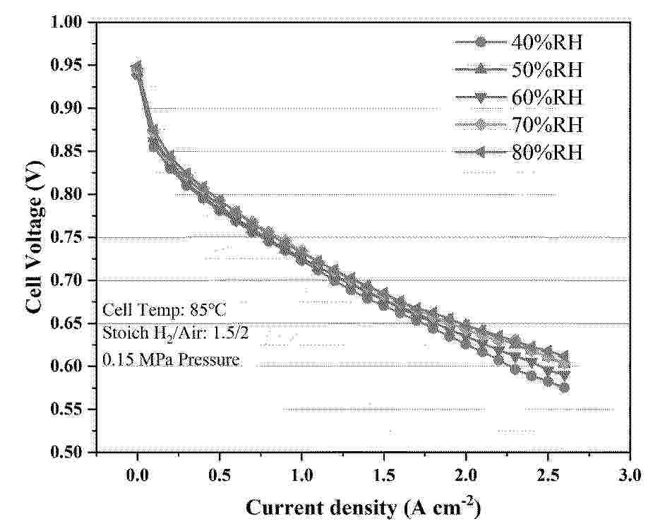
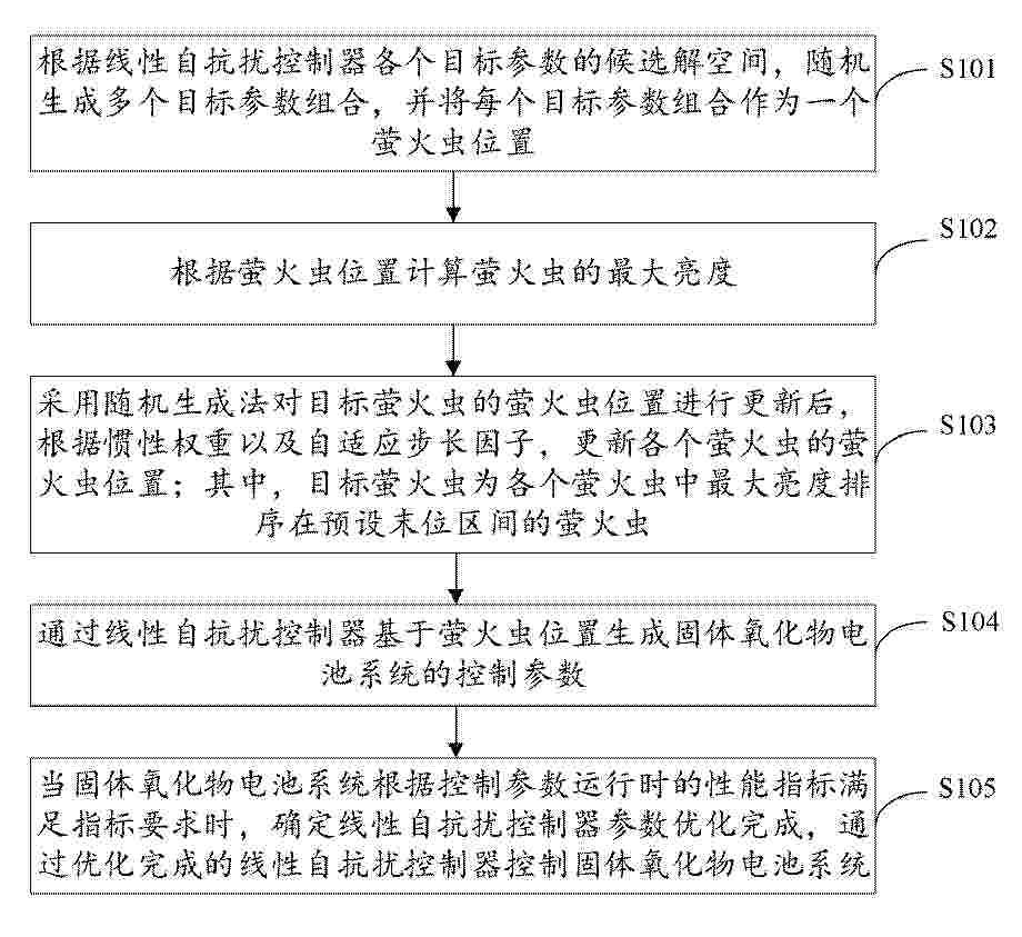
Resumen de: CN121709665A
本发明涉及一种固体氧化物电池自抗扰控制方法,属于自动控制技术领域,其中,该方法包括:根据LADRC各个目标参数的候选解空间随机生成多个目标参数组合,并将每个目标参数组合作为一个萤火虫位置,并根据萤火虫位置计算萤火虫的最大亮度;对最大亮度排序靠后的目标萤火虫的萤火虫位置进行更新后,根据惯性权重以及自适应步长因子更新各个萤火虫的萤火虫位置;然后通过LADRC基于萤火虫位置生成SOC系统的控制参数,当SOC系统根据控制参数运行时的性能指标满足指标要求时,确定LADRC参数优化完成。本发明将改进萤火虫算法应用到SOC系统的自抗扰控制器中进行参数优化,从而提高固体氧化物电池输出电压的抗干扰能力。
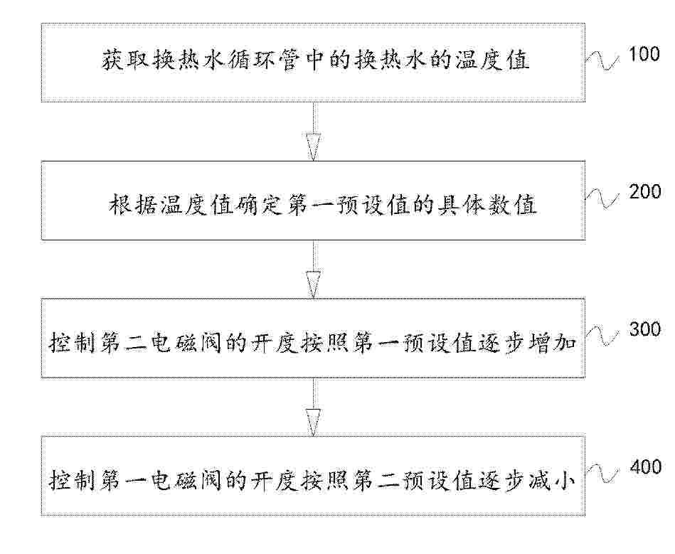
Resumen de: CN121709661A
本发明涉及燃料电池技术领域,具体提供一种燃料电池余热回收系统的控制方法及余热回收系统。具体地,本发明的燃料电池余热回收系统包括燃料电池、换热器、蓄热水箱和换热水循环管,换热器的两端均与燃料电池的冷却液出口和冷却液进口连通,燃料电池与散热器和换热器之间分别设有第一电磁阀和第二电磁阀;换热水循环管将换热器与蓄热水箱连通,控制方法包括:在需要由所述散热模式切换至所述热回收模式时,先控制所述第二电磁阀打开一段时间后再控制所述第一电磁阀关闭。通过这样的设置,有利于避免出现因为换热水温度低导致迅速拉低燃料电池的电堆温度的情况,有利于维持燃料电池的电堆温度的稳定性。
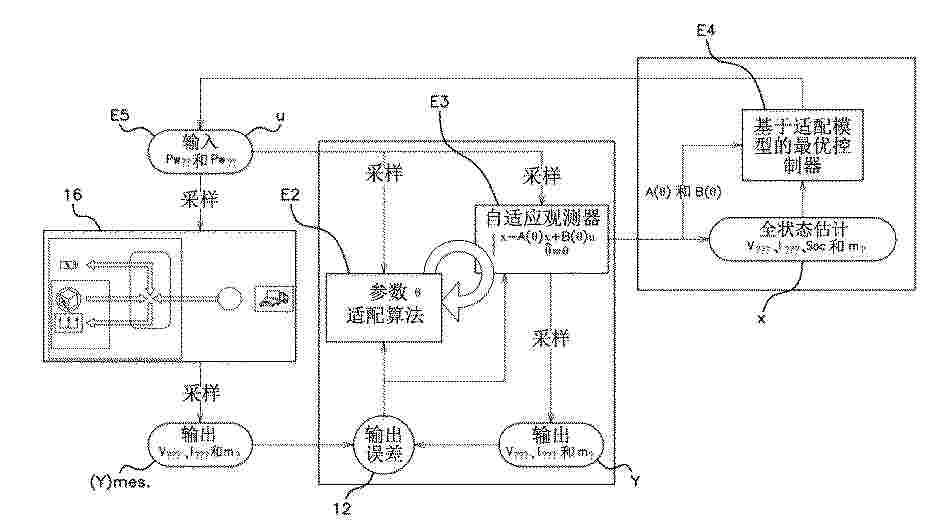
Resumen de: WO2025104148A1
The present invention relates to a method for determining at least one control setpoint ut of a system comprising, at a time t: - a set of input quantities comprising the control setpoint ut and modelled in the form of a vector: Ut, - a set of output quantities modelled in the form of a vector: Yt, and - a set of quantities representing the state of the system and modelled in the form of a vector: xt; the method being implemented in a computing unit and comprising: - a first step E1 of programming a set of linear differential equations relating the input quantities, the quantities representing the state of the system and the output quantities, and - a step E4 of determining the optimal control setpoint by means of the quadratic programming method.
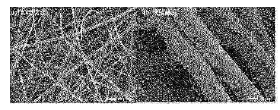
Resumen de: CN121709647A
本发明公开了一种金属氧化物和无机氧化物负载的柔性碳纳米纤维电极材料及其锌锰液流电池,属于电化学储能材料技术领域。本发明以碳毡为基底,采用静电纺丝‑预氧化‑碳化技术,在其表面复合负载金属氧化物和二氧化硅纳米颗粒的碳纳米纤维膜,形成从1微米到100微米孔隙结构的碳电极。该复合电极可利用碳毡的大孔径实现高电解液渗透率与锌离子传输率,同时通过碳纳米纤维中均匀分布的金属氧化物和二氧化硅纳米颗粒,增强亲锌性能、增加锌成核位点,引导锌均匀沉积。本发明应用于锌锰液流电池负极,能显著抑制锌枝晶生长,提升电池库仑效率与能量效率,延长电池寿命,且制备工艺简单、成本低,适合规模化生产,为锌基液流电池在大规模储能领域的应用提供可靠解决方案。
Resumen de: CN121699208A
高温聚合物燃料电池以其良好的耐CO等毒化能力成为目前国际研究的热点。目前PBI/H3PO4膜的常用制备方法为后浸渍法和溶胶‑凝胶法。相比后浸渍法制备PBI/H3PO4膜,溶胶凝胶法具有系列优势,国际上一直致力于开发其制备工艺。然而,高分子量线型聚苯并咪唑是溶胶‑凝胶法制备PBI/H3PO4膜的难点,反应过程中,反应溶液的质、热等很容易出现分布不均的问题,造成反应终止或反应物聚合度在局部明显差异,最终造成无法制备高分子量线型聚苯并咪唑。本方法,通过改变单体比例或/与当反应到一定程度后降低反应液浓度方法能有效地避免由于反应液粘度骤增带来的传质、传热问题,制备出高分子量线型PBI,从而得到高性能的PBI/H3PO4膜。
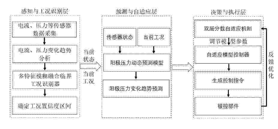
Resumen de: CN121709667A
本发明提供了一种燃料电池阳极压力波动抑制方法及系统,涉及电池智能控制技术领域,包括:对目标燃料电池的电堆运行情况进行实时感知,得到电堆运行状态参数;基于电堆运行状态参数,进行临界工况识别、压力趋势预测和自适应模型预测控制,决策出平衡压力稳定性、动作平滑性和系统能效的最优控制指令;将最优控制指令转化为引射器前端的比例阀开度和阳极循环泵的转速,通过改变开度和转速,最终调节进入阳极的氢气流量和再循环气量,以抑制目标燃料电池的阳极压力波动;本发明通过多层次的信息融合与决策优化,实现对阳极压力的精准、平滑控制,显著提升燃料电池系统的动态性能与可靠性。
Resumen de: WO2025008718A1
A process for producing an iron chromium electrolyte, the process includes leaching iron and chromium from a ferrochrome alloy at an elevated leaching temperature, using hydrochloric acid. A raw iron chromium electrolyte comprising dissolved iron and dissolved chromium is produced. The raw electrolyte is purified and adjusted to produce a functional iron chromium electrolyte.
Nº publicación: CN121713291A 20/03/2026
Solicitante:
松下知识产权经营株式会社
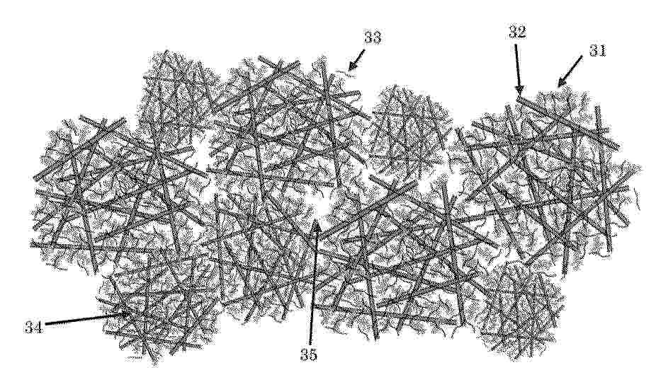
Resumen de: WO2025079699A1
Provided is a gas diffusion layer that maintains the inside of an MEA in a water-containing state and that has sufficient gas permeability and water discharge properties. The gas diffusion layer includes a sheet of a composite powder including conductive particles, conductive fibers, and polymer resin. A grain boundary of the composite powder exists on a surface or in a cross section of the gas diffusion layer, the composite powder including the conductive particles, the conductive fibers, and the polymer resin.
 BOPI
BOPI
 Sede Electrónica