Si deseas distinguir tus productos, servicios o ambos de los de otra empresa, es posible que necesites una marca o nombre comercial. Descubre qué son, en qué consiste su procedimiento de registro y qué implica.

Información sobre los plazos de presentación de solicitudes de transformación de marcas de la Unión Europea en marca nacional española. Más información


Si tienes un nuevo dispositivo, producto o procedimiento que resuelva un problema técnico o tenga una ventaja práctica, existen distintas formas de protegerlo en España y en otros países. Descubre cómo hacerlo.

¿Tu innovación reside en la estética, la ornamentación o la apariencia de tu producto? Protégela mediante un diseño industrial. Descubre qué derechos confiere el registro y cómo realizar la tramitación.

Las indicaciones geográficas protegen el nombre de un producto originario de una zona geográfica, a la cual le debe una determinada calidad, reputación u otra característica. Descubre qué son, en qué consiste su procedimiento de registro y qué beneficios conceden.

Las patentes publicadas en todo el mundo son una valiosa fuente de información científica, técnica y comercial.

Si eres emprendedor/a o una empresa y quieres potenciar y mejorar la rentabilidad de tu negocio protegiendo de forma adecuada los activos intangibles de tu organización, en este espacio encontrarás lo necesario.


 391
resultados
391
resultados
 Última actualización
28/06/2026 [06:47:00]
Última actualización
28/06/2026 [06:47:00]


 Resultados 325 a 350 de 391

Resumen de: CN122224887A
本申请公开了一种燃料电池系统的开机过程控制方法,包括:令燃料电池系统的氢气子系统、空气子系统、和热管理子系统进入各自的第一状态模式中运行预定的第一时间段;在所述第一时间段后,令燃料电池系统的氢气子系统、空气子系统、和热管理子系统进入各自的第二状态模式中运行预定的第二时间段,其中,如果空气子系统在以其第二状态模式运行之前,燃料电池系统的电堆的阳极侧压力或阴极侧压力小于预定的压力值,则在所述空气子系统的第一状态模式中,令所述燃料电池系统的电堆的阴极气体出口与所述燃料电池系统的废气排出子系统之间的流体管路先导通再截止;如果空气子系统在以其第二状态模式运行之前,燃料电池系统的电堆的阳极侧压力或阴极侧压力等于或大于预定的压力值,则在所述空气子系统的第一状态模式中,令所述燃料电池系统的电堆的阴极气体出口与所述燃料电池系统的废气排出子系统之间的流体管路直接截止。

Resumen de: CN122224889A
本发明提供一种智能化多参数调控的液流电池运行系统及方法,属于液流电池技术领域。通过紫外可见吸收光谱仪在线监测电解液中活性物质的价态、浓度及副产物生成情况,结合多传感器对温度、流量、电压等运行参数的实时采集,实现对电池内部状态的全面感知与早期故障诊断,为精准调控提供数据基础。基于实时监测数据,控制模块可动态调节电解液流量、配比、温度及充放电策略,实现多运行参数的协同优化。系统可根据电池荷电状态、工况负载及电解液活性物质浓度,自适应调整充放电策略与电解液补充机制,使电堆始终处于最优反应环境,在保证安全的前提下最大化能量输出,提高能量利用率与系统续航能力。
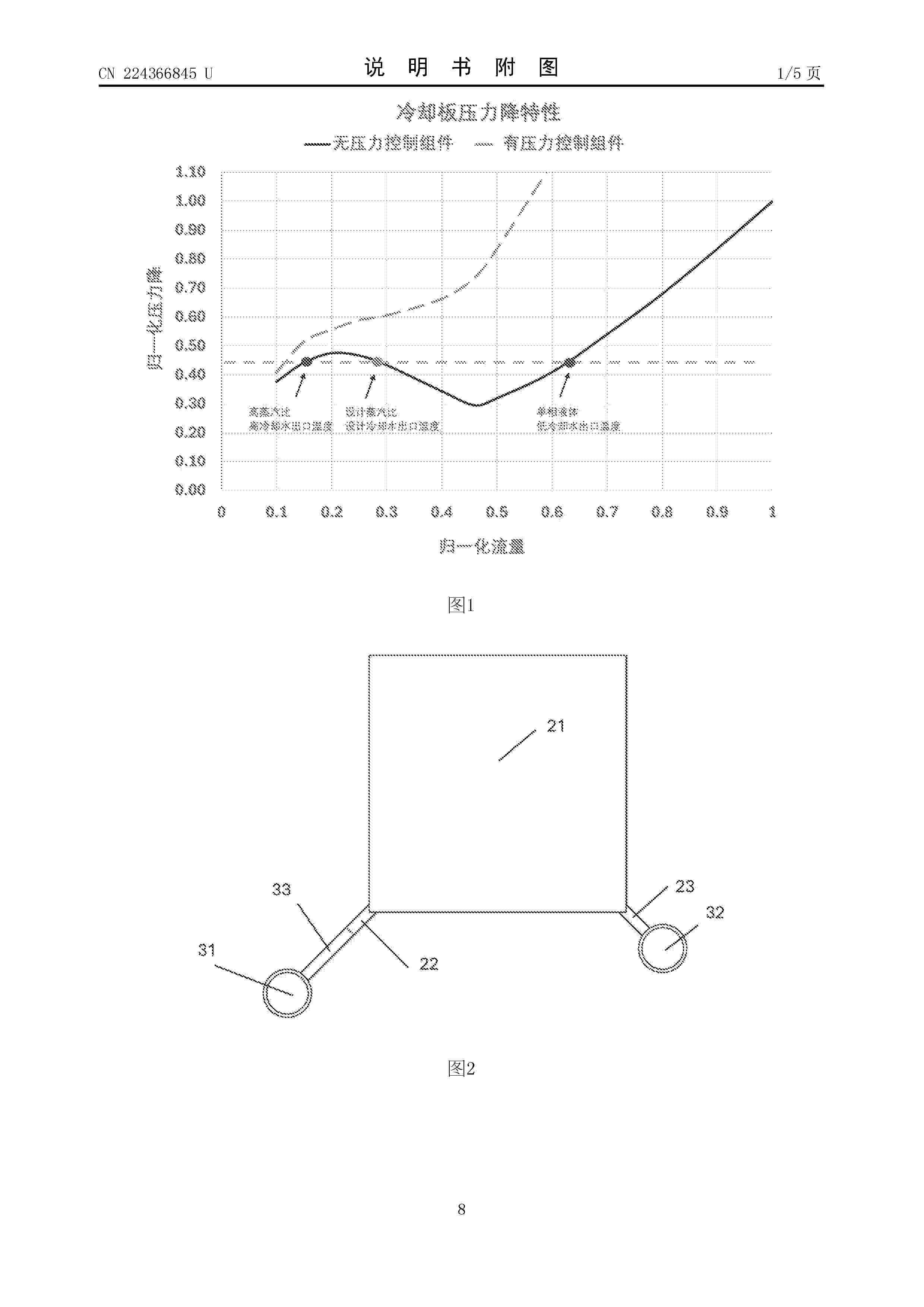
Resumen de: CN224366845U
本实用新型公开了一种磷酸燃料电池冷却组件和磷酸燃料电池电堆,涉及磷酸燃料电池技术领域。其包括:冷却板组件、冷却流体导入歧管、冷却流体导出歧管和流孔结构组件,冷却流体导入歧管和冷却流体导出歧管分别与冷却板组件的冷却流体入口和出口连通;流孔结构组件对应设置在冷却流体导入歧管和冷却板冷却流体入口之间;流孔结构组件由导流孔组成,导流孔从前到后依次包括流体导入区、流体收缩区、流孔、流体扩张区和流体导出区。本实用新型通过在冷却板组件的入口处设置流孔结构组件,并通过流孔结构组件的流孔设计,调整流体通过其的压力降,从而使冷却流体在各个冷却板中均匀分配,提升燃料电池电堆的整体效率并延长电堆组件的使用寿命。
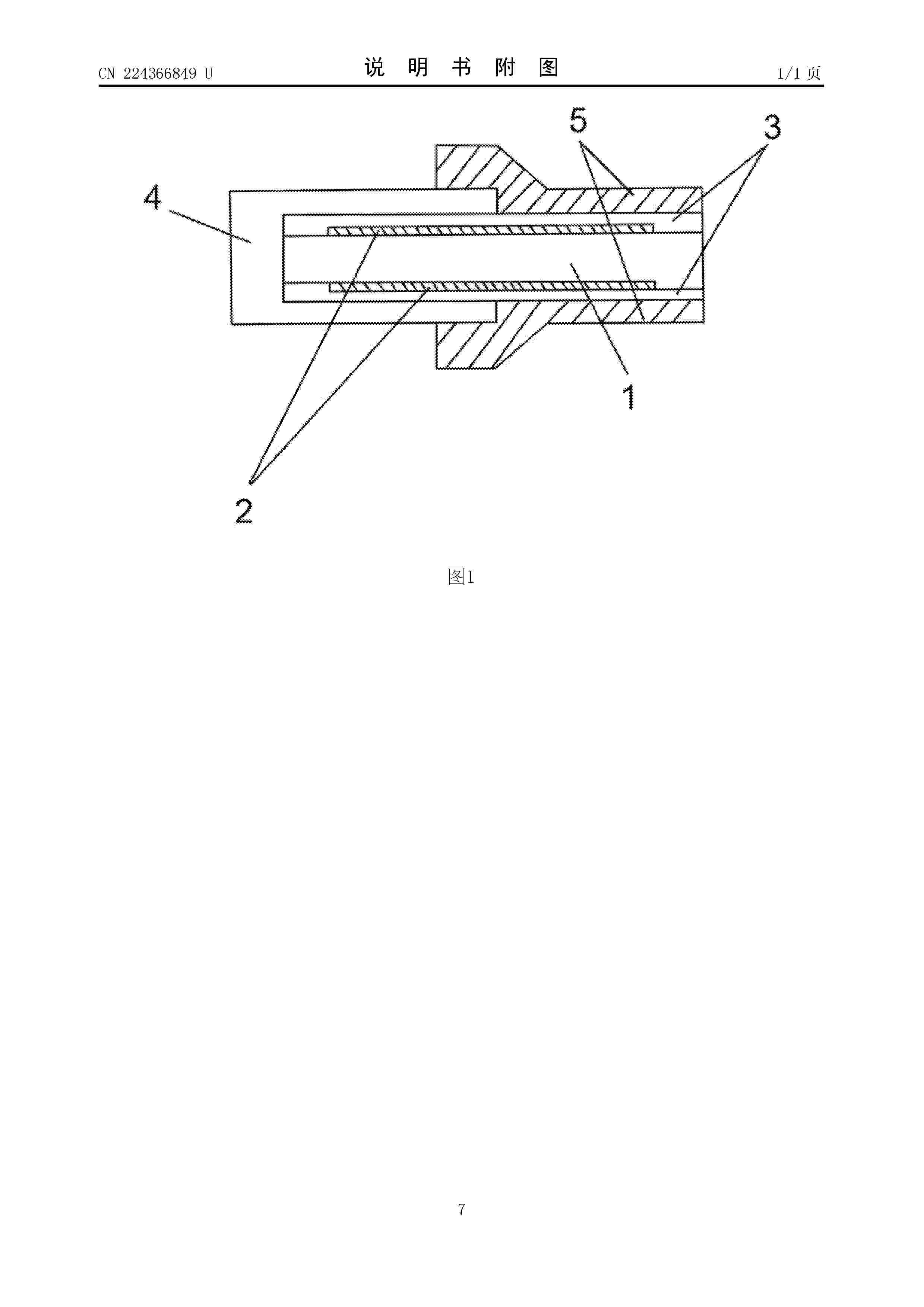
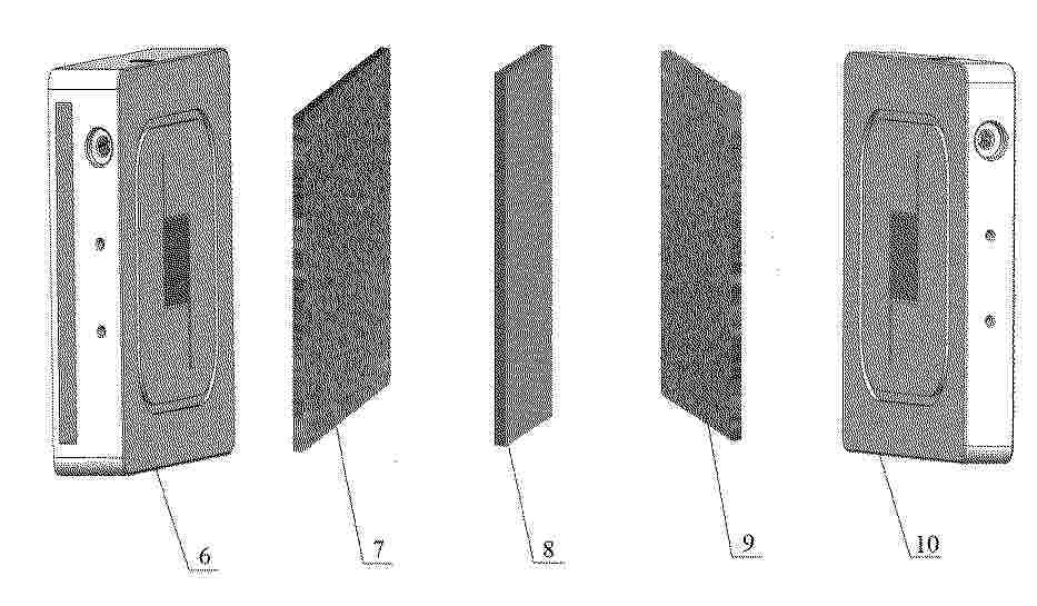
Resumen de: CN224366849U
本实用新型提出了一种简易燃料电池膜电极组件及燃料电池,包括质子交换膜和设置在质子交换膜两侧的电极,所述电极的外侧设有U型边框,且质子交换膜和电极的端部均接触U型边框的内底部。本实用新型采用"U"形边框替代传统多层复合结构,使得质子交换膜和电极刚好嵌入"U"形边框内,避免多次精密对位容易产生偏差影响电极的性能;并且便于U型边框与电极通过热压嵌入工艺进行紧密结合,提升了组装效率。
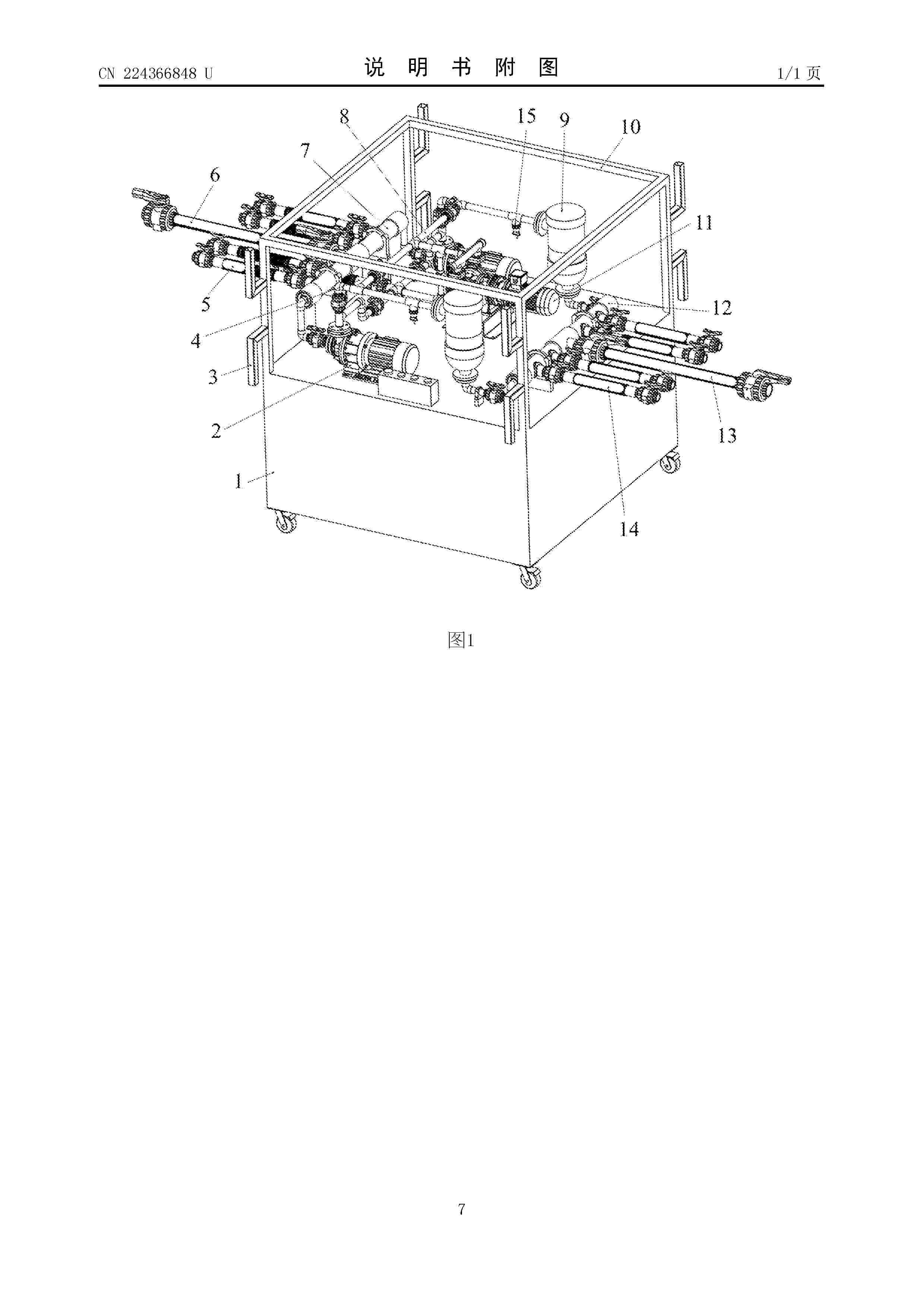
Resumen de: CN224366848U
本实用新型提供一种全钒液流电池的输液设备,涉及液流储能设备领域,针对目前磁力泵及管道初始存在空气导致初始输液需在储罐端临时增加设备填充电解液,引起效率低下的问题,设备配置隔膜泵,其入口端通过第一管路接入过滤器与磁力泵出口端的管道,出口端通过第二管路接入该管道并连通第五输液管,启动时先运行隔膜泵,利用其抽吸能力将电解液从储罐或吨桶中引入,填充第一汇流管、磁力泵及管道,排出空气,使磁力泵快速进入液体工作状态,避免额外临时设备辅助。
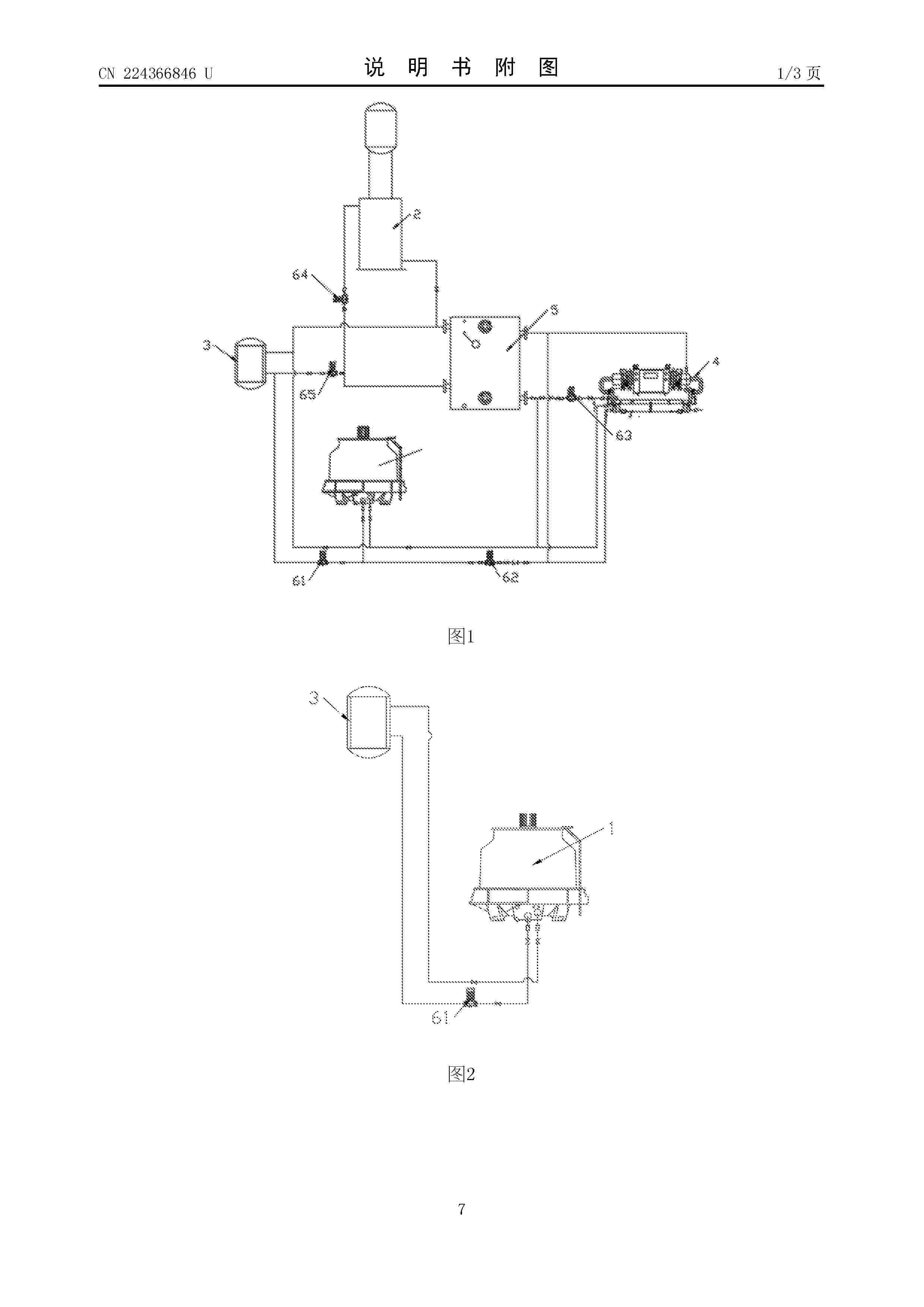
Resumen de: CN224366846U
本实用新型公开了一种全钒液流冷却系统设备,属于全钒液流电池技术领域;包括冷却塔、电解液A罐冷却结构、电解液B罐冷却结构、水冷机组、储水箱;B罐第一冷却线路;B罐第二冷却线路;A罐第一冷却线路;A罐第二冷却线路;本实用新型通过多条冷却线路对电解液A罐冷却结构及电解液B罐冷却结构提供冷却液,能够实现两个电解液罐分别冷却,并且在不同气温条件下,还可以通过切换冷却线路选择不同的冷却条件,适用不同的冷却需求,并节省能耗。
Resumen de: CN122224893A
本公开提供一种基于热/电协同制氢反应器的甲醇燃料电池系统,包括:制热子系统,用于以燃烧方式回收制氢子系统排出的重整尾气,为甲醇水溶液气化与制氢反应提供热能;发电子系统,用于将氢气转化为电能,同时为制氢反应提供电能;制氢子系统,用于在热能与电能的协同驱动下,使甲醇蒸汽与水蒸气发生热化学重整与电化学解离反应,生成高纯度氢气;控制子系统,根据温度反馈动态调节甲醇水溶液输入量及电能分配。本系统通过制热、发电子与制氢温区一致设计与一体化堆叠,实现了系统各部件间的直接接触与零距离氢气输送,大幅减小了系统体积与重量;同时利用燃料电池废热直接用于甲醇水溶液汽化,燃烧室与反应器一体化设计实现热量直接传导,形成了高效的热耦合结构,显著提升了系统的功率密度与能量利用效率。
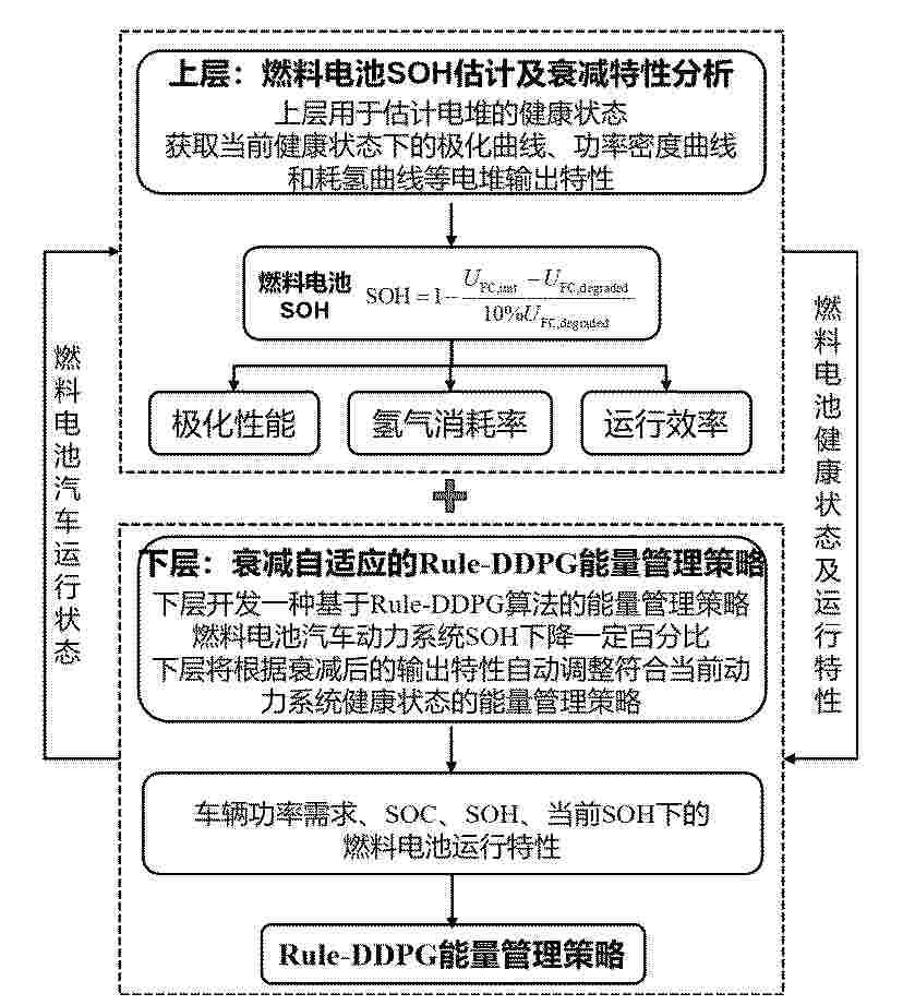
Resumen de: CN122211256A
本发明适用于燃料电池汽车能量管理技术领域,提供了一种自适应健康状态的分层燃料电池汽车能量管理方法,该方法通过分层架构:上层定期估计燃料电池与动力电池的健康状态,获取当前SOH下的输出特性;下层基于Rule‑DDPG算法,根据衰减后的输出特性自适应调整功率分配策略。本发明将SOH、动力电池SOC及需求功率作为状态变量,设计多目标奖励函数,实现了对燃料电池启停、变载、怠速等不良工况的有效抑制。本发明能够使动力系统在全寿命周期内保持最佳工作状态,显著提升燃料电池汽车的经济性与耐久性,具有较强的实时性与工程应用价值。
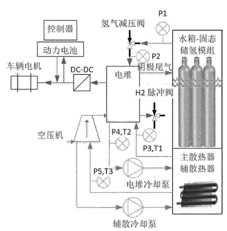
Resumen de: CN122216514A
本发明涉及氢能车载应用技术领域,具体公开了一种固态储氢瓶组在道路洗扫车上的集成方法及应用,解决了固态储氢车载应用中空间占用大、热管理复杂、车辆运营能耗高的技术问题。该方法将固态储氢瓶组集成于洗扫车清水箱内,利用水箱闲置空间实现储氢系统与洗扫车核心部件的深度融合;以水箱水体为热管理介质,通过水循环完成储氢瓶组加氢时的冷却和释氢时的加热,同时回收燃料电池废热加热洗扫用水;并匹配混合动力控制模块实现电堆与动力电池的功率协同调控。本发明实现了空间的极致利用,简化了热管理系统设计,降低了车辆运营能耗和系统成本,优化了洗扫车重心分布,提升了整车行驶稳定性和安全性,同时保证了氢能洗扫车的实用续航里程和洗扫作业效能,为固态储氢在特种车辆上的商业化应用提供了新方案。
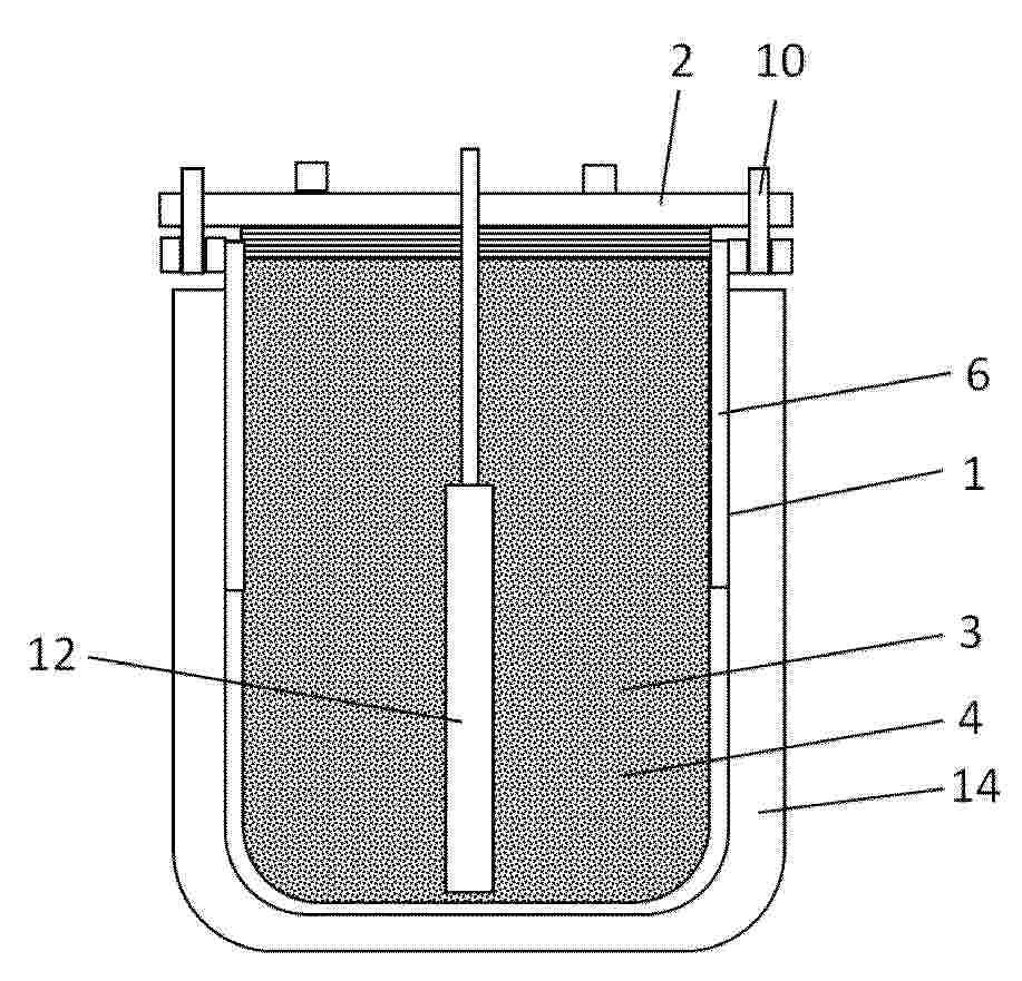
Resumen de: CN122209305A
一种安全可靠的固态氢化物水解制氢燃料罐,上盖通过螺栓与壳体可拆卸连接,从而可以多次重复使用。由于内胆是烧结多孔结构,因此不会形成封闭承压腔,不承受机械压力,不会因压力过高而变形、破裂,压力由壳体承担,而且在外部压力突然下降时,内胆通过孔隙也可以快速泄压,防止破裂而导致粉尘飘出形成粉尘云,降低粉尘爆炸的风险。类似的,以固态氢化物加热分解产氢的设备同样有类似的突然压力失控的问题,该设计同样适用于此类应用。壳体内部设置台阶来固定石墨纸,避免长时间放置后石墨纸下移。上盖的各个出气口的下侧焊接有多孔结构,以避免燃料罐内里的固态氢化物粉颗粒直接从出气口冲出燃料罐。
Resumen de: CN122224865A
本发明公开了一种含单壁碳纳米管的催化剂浆料及其在膜电极和电解池中的应用。该浆料按重量份计,包含催化剂1‑10份、单壁碳纳米管0.1‑5份、离聚物0.5‑8份、分散溶剂80‑98份及分散剂0.01‑2份。其制备方法通过分级超声分散工艺,先将官能团化(羧基或羟基)的单壁碳纳米管与分散剂预分散,再与催化剂、离聚物共混精散,实现了单壁碳纳米管在浆料中的稳定、均匀分散。利用该浆料制备的膜电极,在质子交换膜燃料电池及水电解池中应用时,单壁碳纳米管能在催化剂层内构建高效三维导电网络、优化孔道结构并增强机械稳定性,从而显著提升电化学性能、改善传质并大幅增强耐久性。
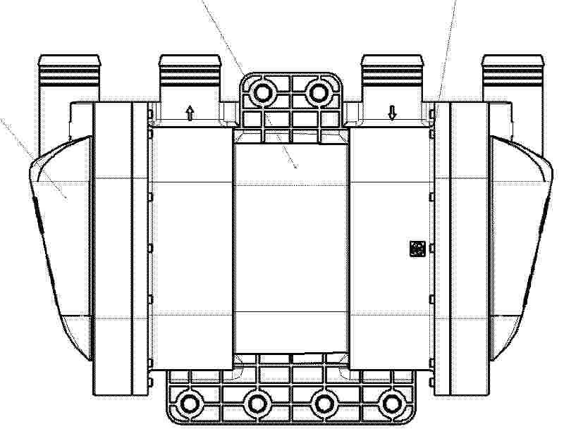
Resumen de: CN122224882A
本发明公开了一种可维护的模块化增湿装置,属于氢燃料电池电堆系统技术领域。针对现有增湿器一体式封装不可维护的问题,提出一种可根据需求灵活配置膜组件数量的模块化架构。该装置包括外壳、端盖、隔板、密封圈、螺栓及若干膜组件,膜组件沿垂直于轴向并排布置于外壳内,两端分别布置隔板,隔板与外壳之间布置防止湿空气与干空气串气的密封圈,隔板与端盖之间布置防止干空气外泄的密封圈,端盖与外壳通过螺栓连接提供轴向压紧力,松开螺栓可拆卸端盖、隔板及密封圈以实现膜组件的单独维护或更换。本发明在保证高气密性防止内外泄漏的前提下实现了膜组件的便捷维护及平台化灵活配置,降低了全生命周期成本,缩短了产品开发周期。
Resumen de: CN122224891A
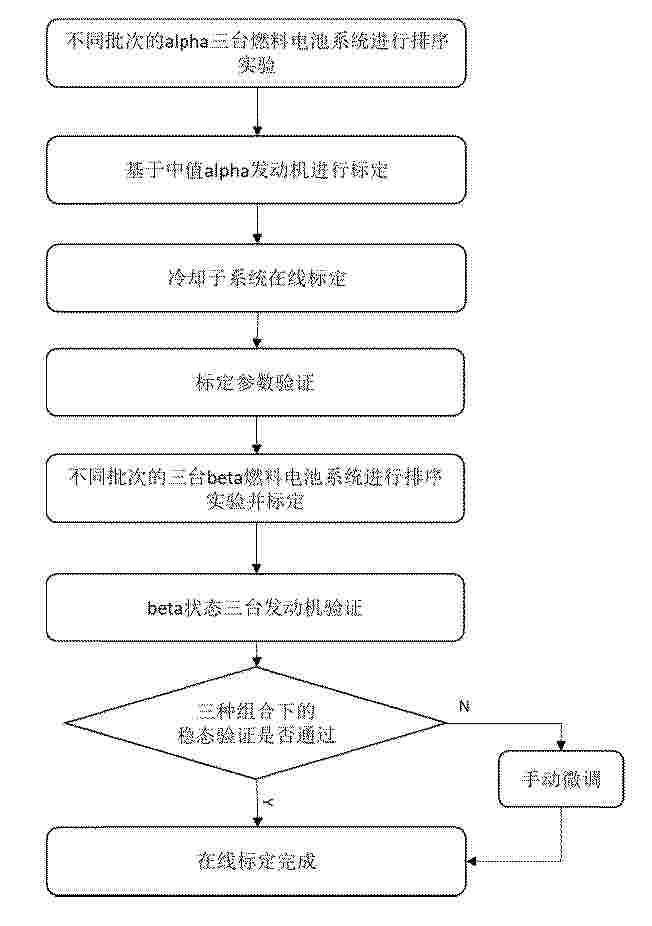
本发明公开了一种氢燃料电池冷却子系统在线标定方法,包括步骤:S1、选取实验用燃料电池系统;S2、确定标定要素:基于标定规则,将冷却子系统的至少三个控制参数作为标定参数,将至少六个反映系统性能的参数作为评价指标,并将所述评价指标写入控制软件;S3、冷却子系统在线标定:冷却子系统处于标定状态时,自动运行标定规则,通过所述评价指标确定最终的标定参数;S4、量产适配标定:对beta状态的燃料电池系统进行标定,使标定结果满足量产要求。本发明的氢燃料电池冷却子系统在线标定方法,通过客观的标定评价指标,保证最终的标定品质在最佳范畴,燃料电池一直运行在最佳操作条件,同时在线标定不需要标定工程师全程跟踪,可以降低企业用人成本,最后通过不间断的标定过程,提高产品研发速度。
Resumen de: CN122224857A
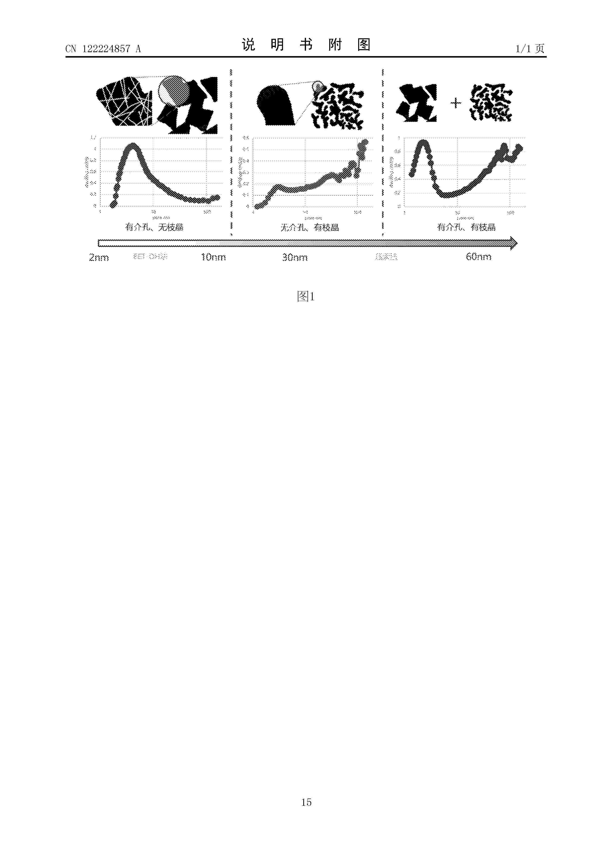
本公开提供了一种燃料电池的催化层,所述催化层中包括催化剂A和催化剂B的组合或催化剂B和催化剂C的组合;所述催化剂A的2~10nm介孔容量小于0.22mL/g,所述催化剂B的2~10nm介孔容量大于0.33mL/g,所述催化剂C的10~20nm介孔容量大于0.22mL/g。本公开还提供了一种燃料电池的催化层的制备方法和一种膜电极。本公开提供的催化层通过引入两种不同介孔类型的催化剂,有效调控了催化层孔隙结构,使膜电极具有高活性高传质性能,从而提高了燃料电池的发电性能。
Resumen de: CN122211560A
本发明提出一种利用可再生资源制氢的海上船舶通过两个氢能系统将可再生能源转化为液氢储存储存至储存单元中,当船舶运行需要能源时,小规模氢能系统中的储存单元将液氢转化氢气输送至燃料电池单元中并产生电能供给船舶使用,大型氢能系统则利用除小规模氢能系统以及船舶所需之外的能源进行生产液氢储存,同时实现向外部输出单元输出液氢,两个氢能系统相互补给,能够完成维持船舶运行同时向外部加注液氢。
Resumen de: CN122219121A
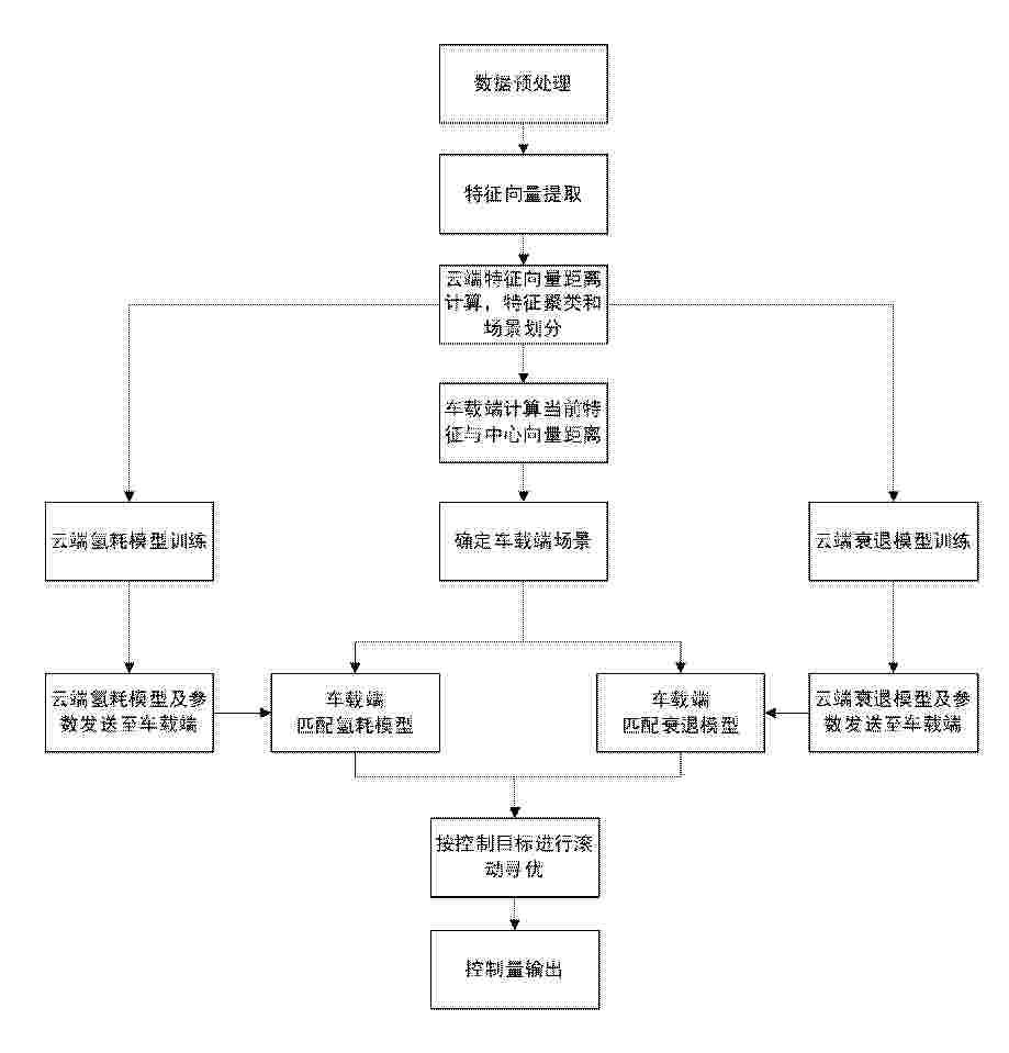
本发明公开了基于云车协同的数据驱动燃料电池系统的预测控制方法,涉及燃料电池动力系统控制与能源管理领域,该方法采集燃料电池车辆运行数据上传至云端;云端对数据进行清洗、特征构建与场景聚类,划分出不同的运行场景;针对每一场景,分别训练数据驱动的氢耗模型与衰退模型;车端控制器基于当前运行场景实时调用对应的氢耗模型与衰退模型,构建以最小化氢耗与电堆衰退速率为目标的模型预测控制优化问题,并在安全约束下求解,输出空气系统与热管理系统的控制指令;本发明通过云端的场景化建模与车端的自适应预测控制,实现了燃料电池系统在全生命周期内效率与寿命的协同优化,可显著降低氢耗并延缓电堆性能衰退。
Resumen de: CN122214888A
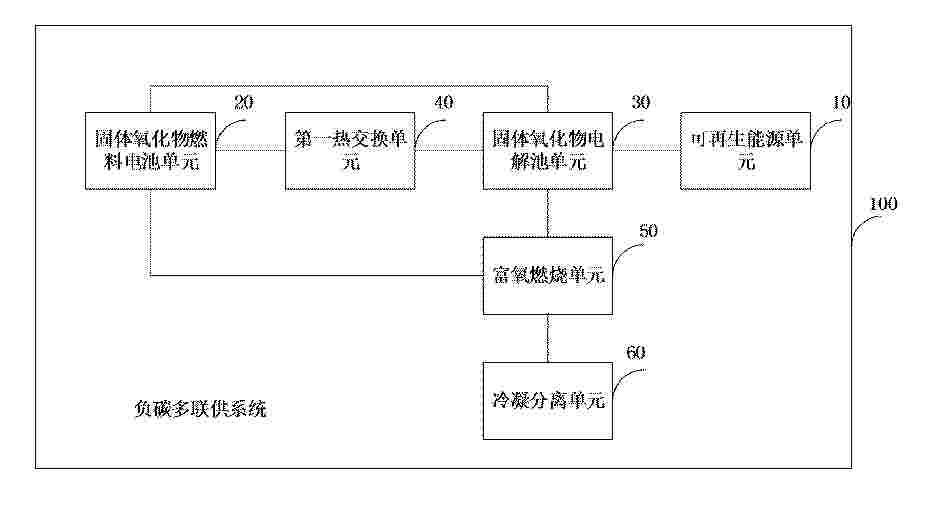
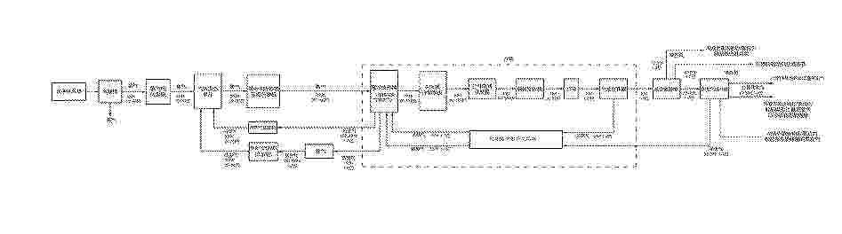
本申请涉及能源利用技术领域,特别涉及一种负碳多联供系统及负碳多联供方法,其中,系统包括:可再生能源单元,用于提供可再生电力;固体氧化物燃料电池单元,用于接收油气区的伴生气和外部的空气,对伴生气和空气进行电化学反应生成第一电力、热能和尾气;第一热交换单元,用于基于热能将电解所需的水加热得到水蒸汽;固体氧化物电解池单元,用于基于可再生电力和/或第一电力、以及热能电解水蒸气,得到第一氢气和氧气;富氧燃烧单元,用于对尾气和氧气进行反应,得到废气;冷凝分离单元,用于对降温后的废气进行分离得到二氧化碳和水。由此,解决了相关技术中伴生气浪费、可再生能源消纳难,且制氢成本较高等问题。
Resumen de: CN122211561A
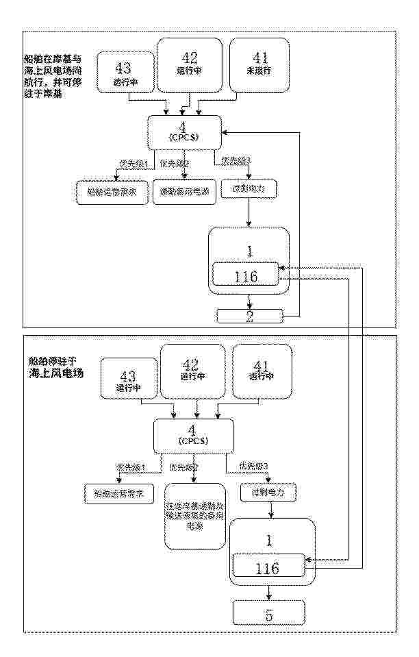
本发明涉及一种海上绿色氢能供应船舶及供应方法,包括船体与船载氢能系统,所述船载氢能系统含利用可再生能源生产液态氢的制氢液化装置、储存液态氢的储罐,以及使用液态氢的燃料电池和商业加注站,储罐被配置为双路径分配液态氢,第一路径供燃料电池为船舶发电,第二路径供商业加注站向其他船舶加注;通过将制氢、储氢、自用发电及商业加注功能集成于船体,形成移动氢能供应枢纽,解决了现有技术中海上绿色氢生产与加注割裂、固定式平台建设维护成本高、供应连续性不足及加注基础设施僵化等问题,实现绿色液态氢自主生产、自我保障与商业化供应一体化运作,填补远海区域绿色氢能加注基础设施空白,为海事领域脱碳提供灵活、高效的解决方案。
Resumen de: CN122224861A
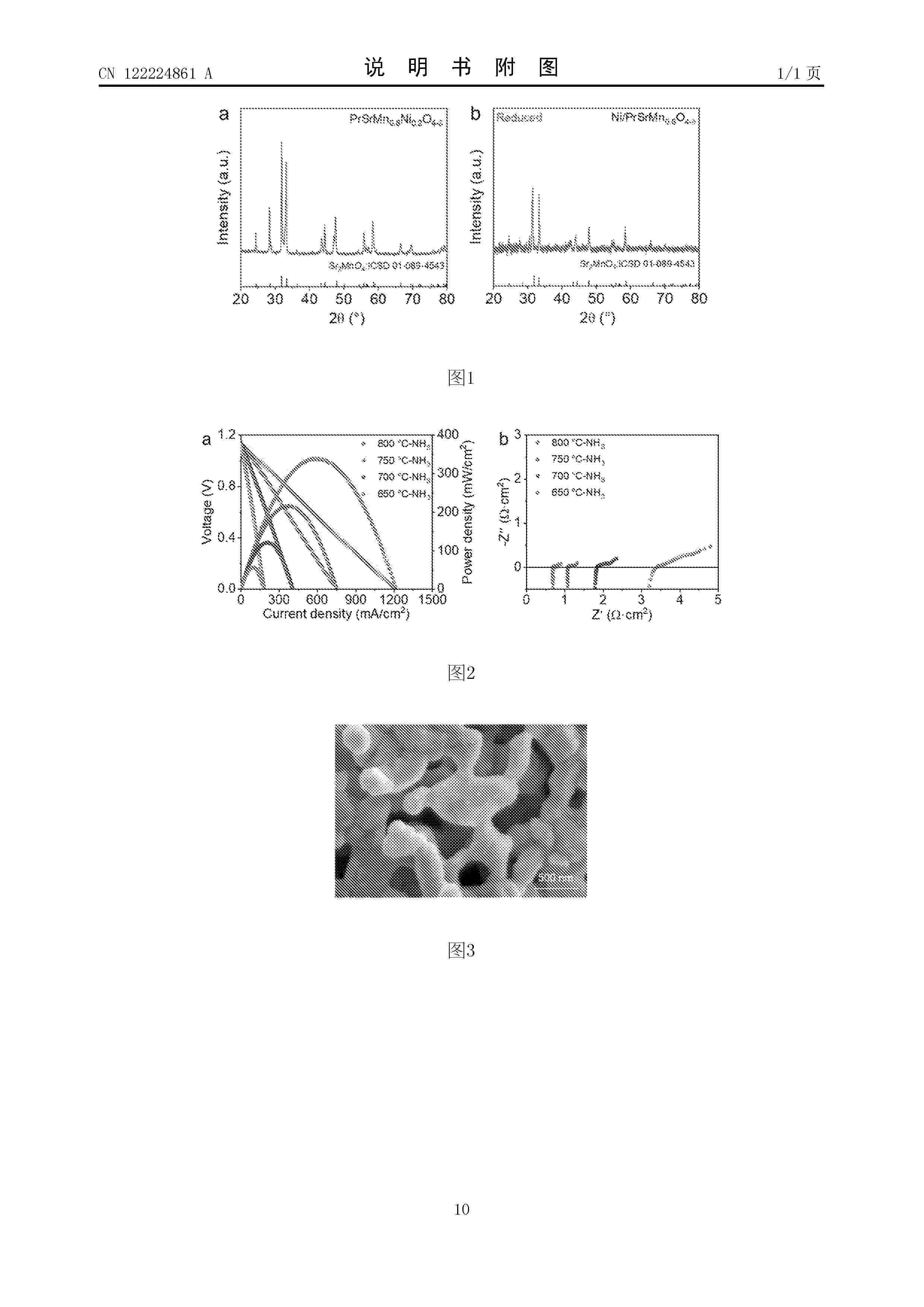
本发明公开了一种基于A位镨元素掺杂的R‑P型钙钛矿阳极催化剂的制备及其在直接氨固体氧化物燃料电池中的应用。通过在A位引入Pr部分取代Sr2Mn0.8Ni0.2O4‑δ的Sr位以制备R‑P型钙钛矿PrSrMn0.8Ni0.2O4‑δ前驱体,该前驱体在还原气氛下发生Ni原位析出,形成Ni纳米颗粒锚定于PrSrMn0.8O4‑δ表面,构建Ni/PrSrMn0.8O4‑δ阳极催化剂。该催化剂表现出优异的氨分解活性与电化学性能,在800 ℃、NH3气氛下的最大功率密度达338 mW·cm‑2,是未掺杂样品的2.1倍。本发明提供的催化剂制备工艺简单、成本低廉,适用于中高温直接氨固体氧化物燃料电池。
Resumen de: CN122213943A
本发明公开了一种氢燃料电池冷却液、制备方法及其应用。所述氢燃料电池冷却液,包含有乙二醇、复合缓蚀剂、铜缓蚀剂、消泡剂和pH值调节剂;所述复合缓蚀剂为R‑联萘酚磷酸酯与N,N‑二(羟基乙基)椰油酰胺的混合物。本发明的氢燃料电池冷却液具备优异的金属缓蚀效果,并且R‑联萘酚磷酸酯和N,N‑二(羟基乙基)椰油酰胺均属于非离子型缓蚀剂,具有较低的电导率,能维持冷却液体系的低电导率水平,不会产生对膜电极造成潜在危害的离子,能有效保证氢燃料电堆的安全运行。
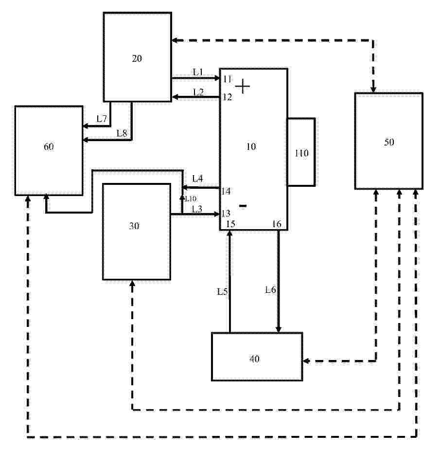
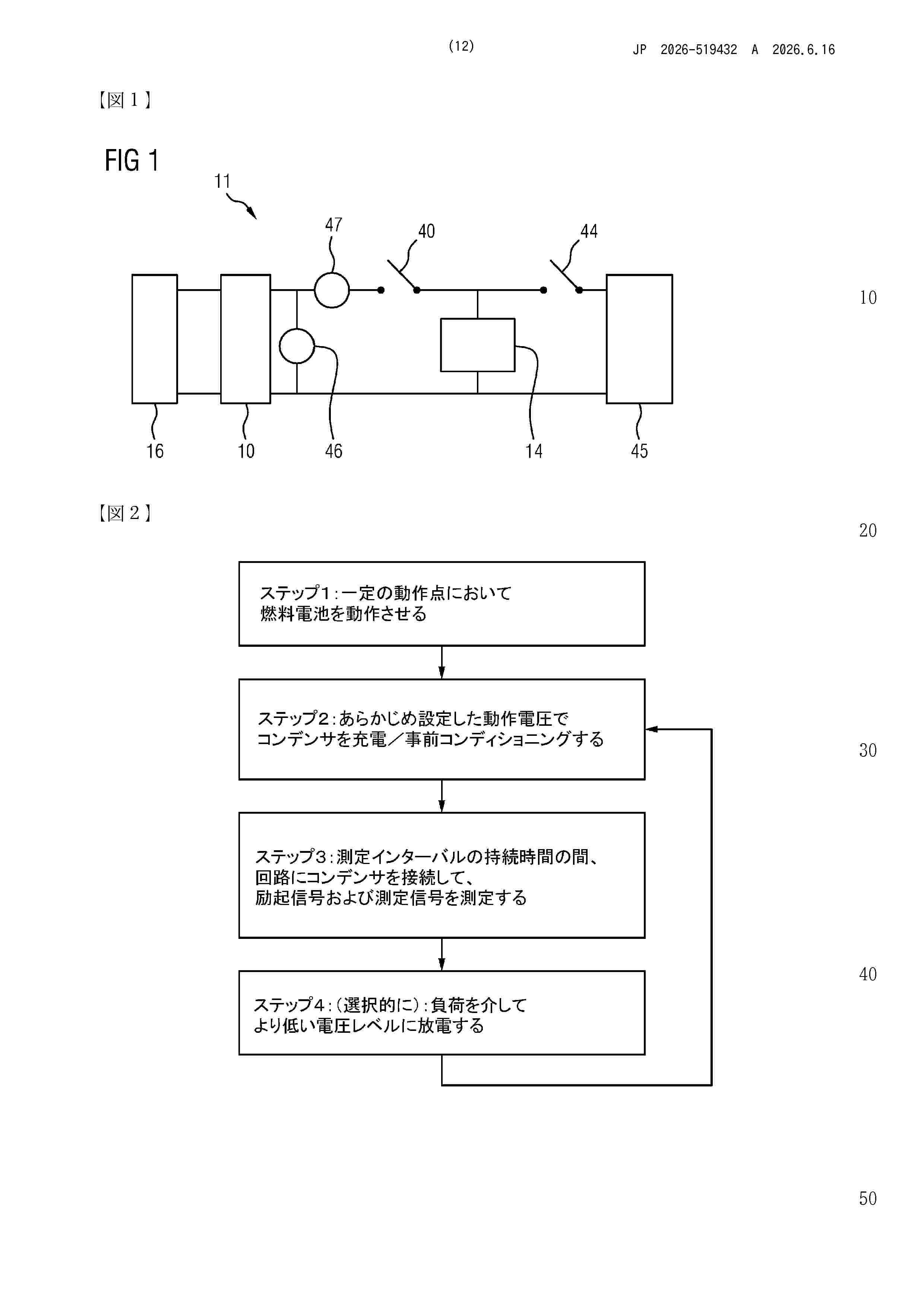
Resumen de: WO2024231357A1
The invention relates to a method and to a measurement arrangement for diagnosing a component to be examined, said method comprising the steps of: operating the component (10) to be examined in an electrical circuit (11) at a predefined operating point for a predefined first measurement interval (12); and, during this first measurement interval, detecting a measurement signal and an excitation signal (13) in the circuit as a function of time, wherein the excitation signal is a signal from a passive component (14) in the circuit, which signal is in a predefined first excitation state (15) at the start of the first measurement interval, and the measurement signal results from a superposition of the excitation signal of the passive component and an operating signal from the component to be examined.
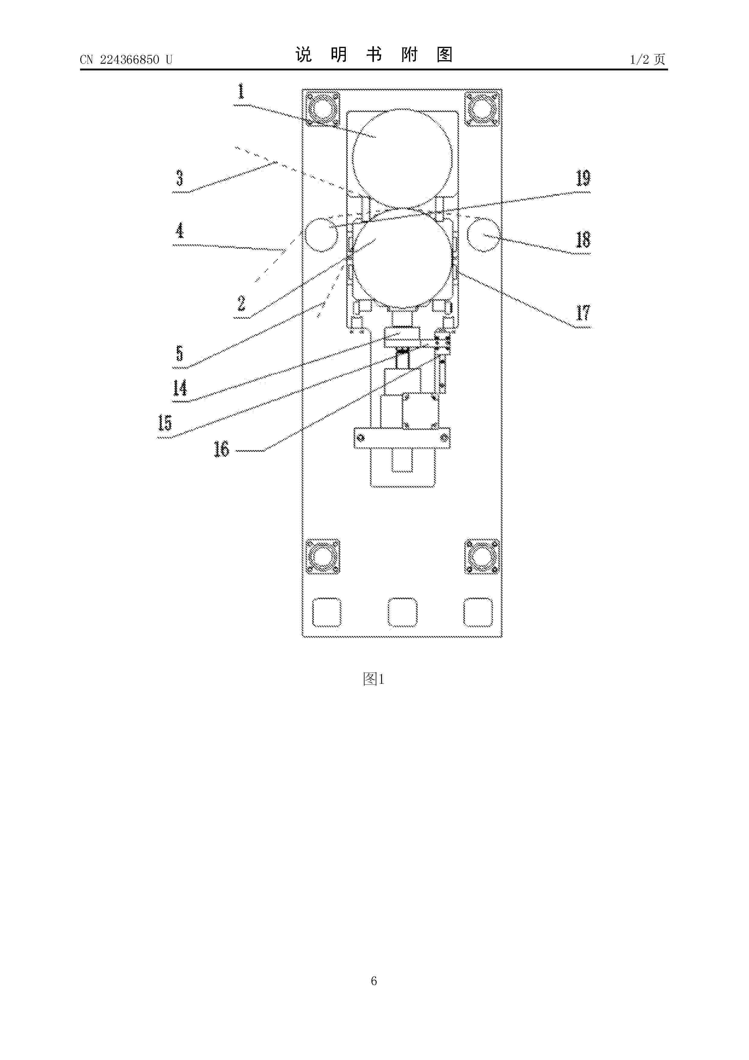
Resumen de: CN224366850U
本实用新型提供了一种用于电池质子交换膜转印生产的热轧复合装置,包括:机架,机架上安装有上下并排紧贴设置的上转印轧辊和下转印轧辊,其中上转印轧辊固定安装在机架上,下转印轧辊安装在机架上设置的滚珠导轨上,下转印轧辊的下方安装有称重传感器安装底座,称重传感器安装底座上安装有称重传感器,称重传感器与下转印轧辊的轴承座接触,称重传感器安装底座安装在机架上设置的直线导轨上,称重传感器安装底座的底部安装有滚珠丝杆升降机,滚珠丝杆升降机的底部安装有丝杆驱动电机。本热轧复合装置结构简单,自动化程度高,可以实现对质子交换膜复合压力的精确控制及多功能多路径的复合转印。
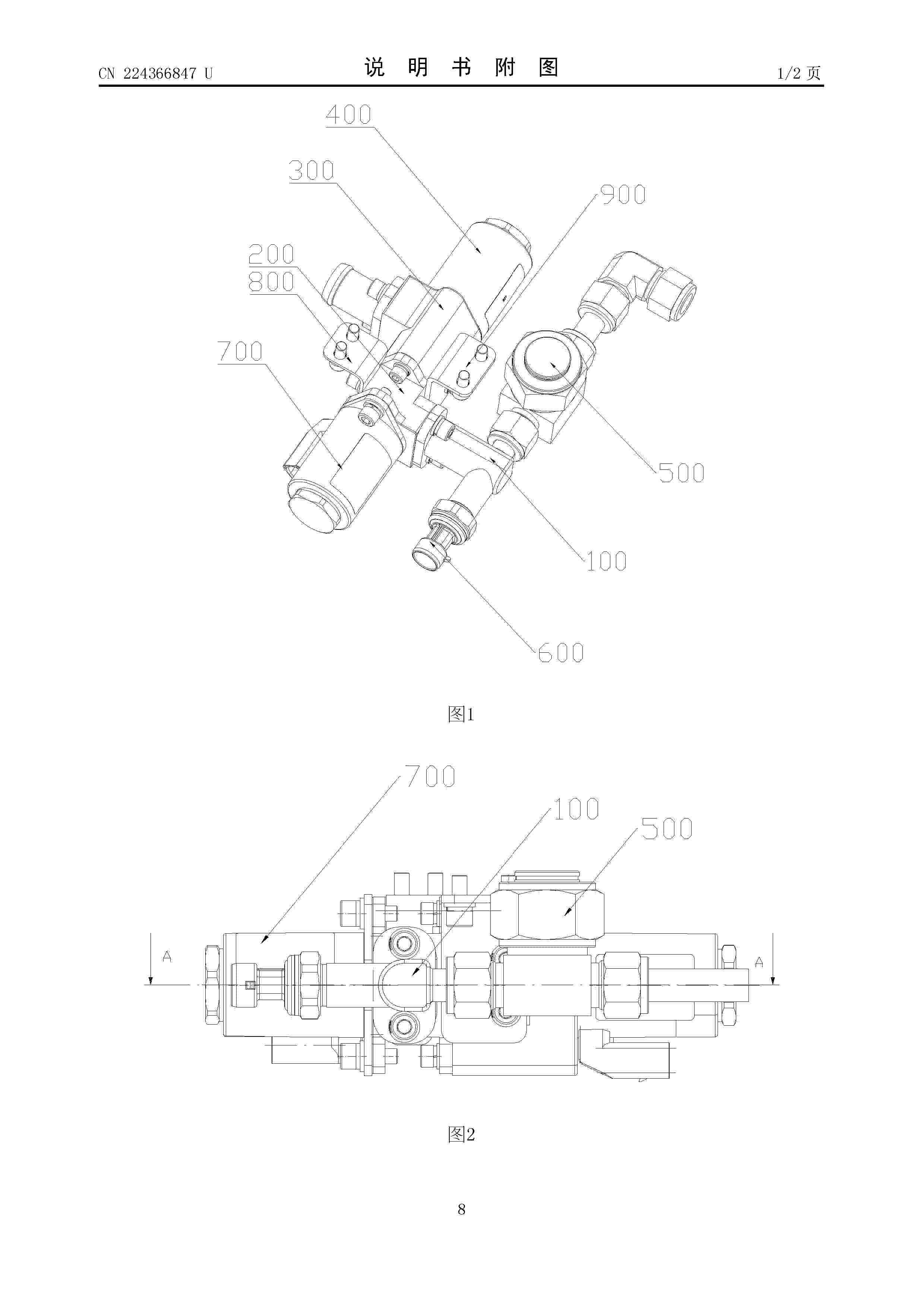
Resumen de: CN224366847U
本实用新型提供了一种燃料电池供氢组件及燃料电池阳极供气系统,涉及新能源电池的技术领域,该燃料电池供氢组件包括供氢第一底座和供氢第二底座;所述氢气过滤器用于过滤进入第三管路内的氢气;所述第二管路的一端设置有进氢阀,另一端设置有比例阀,且在所述比例阀的比例阀座上设置有氢气出口;所述进氢阀用于控制第二管路的通断,所述比例阀用于控制氢气出口的通断。本实用新型提供的一种燃料电池供氢组件的供氢第一底座和供氢第二底座连接,将第一压力传感器、氢气过滤器、比例阀等集成在供氢第一底座和供氢第二底座上,减少了安装孔件,提高了系统集成度,降低了设计复杂性,提高了系统稳定性并减少了氢气泄漏点。
Resumen de: CN122209251A
本发明公开了一种Nafion/氟化COF复合质子交换膜的制备方法,以Nafion为主体,添加氟化COF材料为填充剂,再通过流延法制备得到复合膜。具体而言,采用溶剂热法合成含碱性基团的COF粉末,然后通过接枝全氟烷链制备得到氟化COF粉末,将其与Nafion充分混合,通过流延法制备Nafion/氟化COF复合膜。氟化COF骨架上丰富的胍基与Nafion中的磺酸基团形成质子供‑受体基团结构,降低质子传递能垒,提高质子传递效率。同时,氟化COF中的全氟烷链具有强疏水性,可以抑制Nafion中磺酸基团由于过度吸水而形成尺寸过大的亲水团簇,降低气体渗透率。本方法制备得到的复合膜兼具高质子传导率和低气体渗透率,表现出优异的电化学压缩氢性能和燃料电池性能。
Nº publicación: CN122213413A 16/06/2026
Solicitante:
中北大学
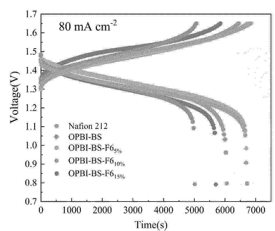
Resumen de: CN122213413A
本发明提供了一种具有超高离子选择性的氟化侧链改性聚苯并咪唑质子交换膜及其制备方法,属于新能源材料与电化学储能技术领域。质子交换膜具有式(I)所示结构,通过同时引入磺酸烷基侧链和全氟烷基侧链对OPBI主链进行功能化修饰,构建兼具高通量质子传输通道和优异钒离子阻隔能力的离子选择性透过膜。本发明实现了膜内离子传输通道尺寸和化学微环境的精细调控,在保持高质子传导率(可达125mS cm‑1)的同时将VO2+渗透率显著降低至3.2×10‑7cm2 h‑1,应用于全钒液流电池的库伦效率高达98.6%以上,能量效率达到92.8%,表现出远超商业Nafion 212膜的综合性能。
 BOPI
BOPI
 Sede Electrónica