Si deseas distinguir tus productos, servicios o ambos de los de otra empresa, es posible que necesites una marca o nombre comercial. Descubre qué son, en qué consiste su procedimiento de registro y qué implica.

Información sobre los plazos de presentación de solicitudes de transformación de marcas de la Unión Europea en marca nacional española. Más información


Si tienes un nuevo dispositivo, producto o procedimiento que resuelva un problema técnico o tenga una ventaja práctica, existen distintas formas de protegerlo en España y en otros países. Descubre cómo hacerlo.

¿Tu innovación reside en la estética, la ornamentación o la apariencia de tu producto? Protégela mediante un diseño industrial. Descubre qué derechos confiere el registro y cómo realizar la tramitación.

Las indicaciones geográficas protegen el nombre de un producto originario de una zona geográfica, a la cual le debe una determinada calidad, reputación u otra característica. Descubre qué son, en qué consiste su procedimiento de registro y qué beneficios conceden.

Las patentes publicadas en todo el mundo son una valiosa fuente de información científica, técnica y comercial.

Si eres emprendedor/a o una empresa y quieres potenciar y mejorar la rentabilidad de tu negocio protegiendo de forma adecuada los activos intangibles de tu organización, en este espacio encontrarás lo necesario.


 391
resultados
391
resultados
 Última actualización
28/06/2026 [06:47:00]
Última actualización
28/06/2026 [06:47:00]


 Resultados 300 a 325 de 391

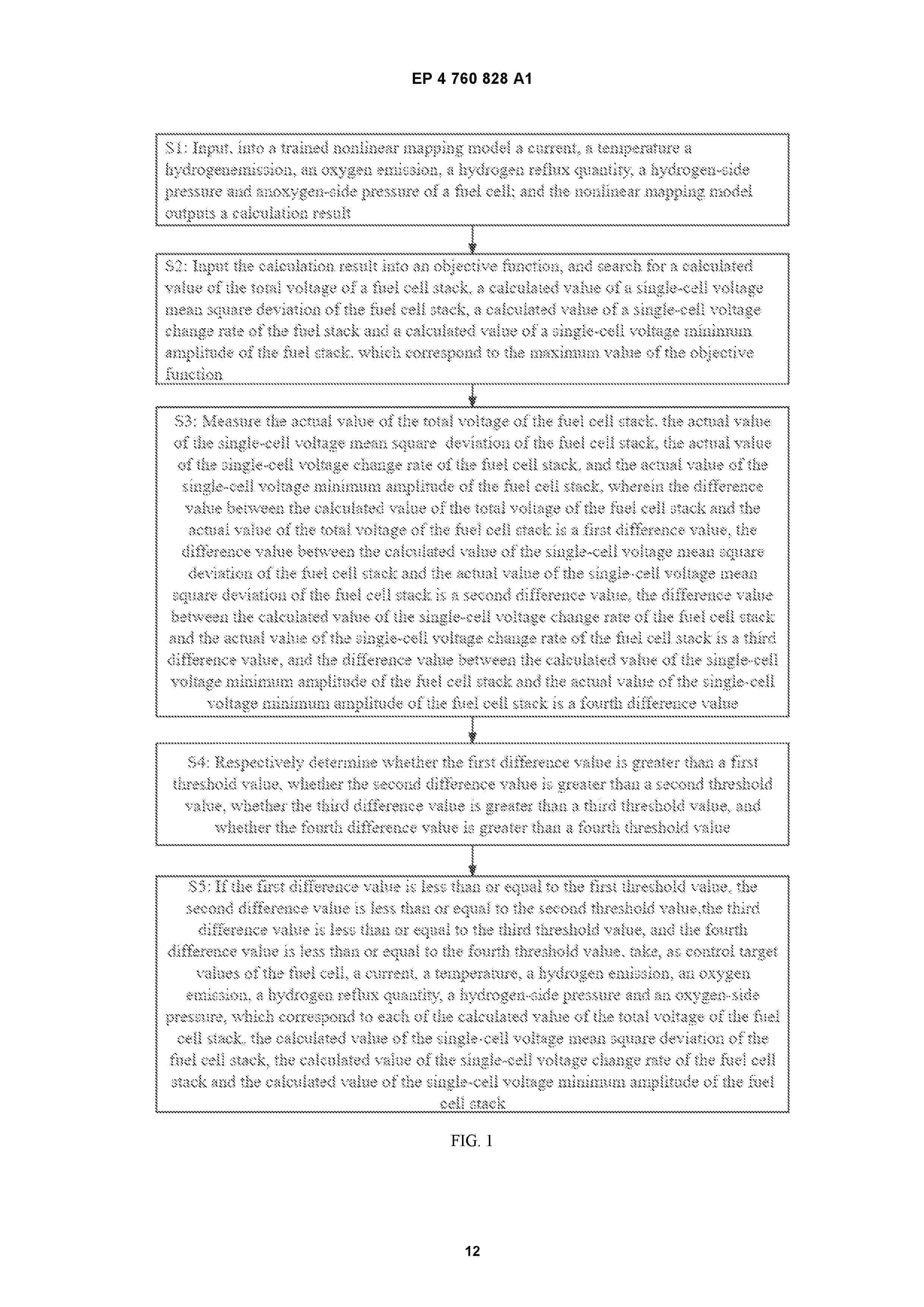
Resumen de: EP4760828A1
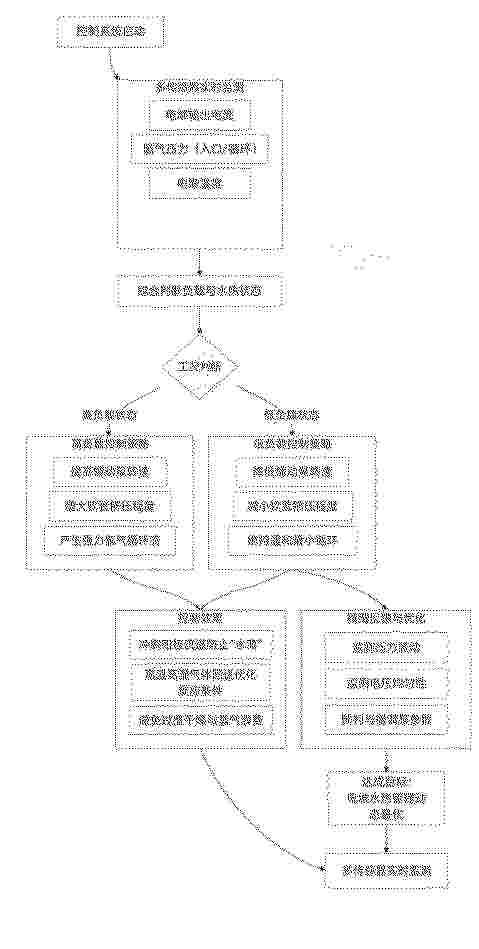
Provided in the present invention is a method for controlling intelligent health management of a fuel cell. The method comprises: taking, as control target values of a fuel cell, a current, a temperature, a hydrogen emission, an oxygen emission, a hydrogen reflux quantity, a hydrogen-side pressure and an oxygen-side pressure, which correspond to each of a calculated value of the total voltage of a fuel cell stack, a calculated value of a single-cell voltage mean square deviation of the fuel cell stack, a calculated value of a single-cell voltage change rate of the fuel cell stack and a calculated value of a single-cell voltage minimum amplitude of the fuel cell stack, or correspond to each of an optimized value of the total voltage of the fuel cell tack, an optimized value of the single-cell voltage mean square deviation of the fuel cell stack, an optimized value of the single-cell voltage change rate of the fuel cell stack and an optimized value of the single-cell voltage minimum amplitude of the fuel cell stack, and thus a membrane electrode is always in a "water balance" state, thereby improving the performance of cells, reducing the occurrence of cell faults, and improving the self-adaptability, reliability and stability of a fuel cell system.

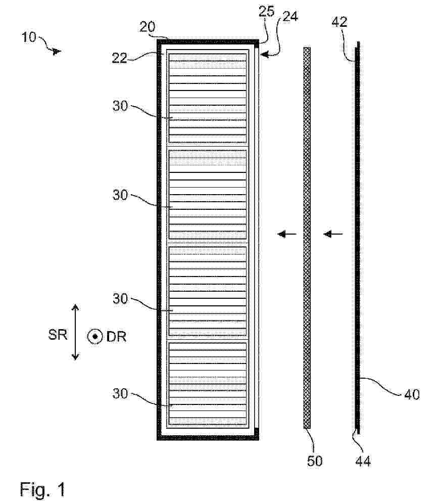
Resumen de: WO2025118010A1
The present invention relates to a fuel cell tower (10) of a fuel cell system having a housing (20), which has a housing space (22), in which at least one fuel cell stack (30) is arranged, wherein the housing (20) has at least one side opening (24), which is closed by means of a side wall (40), wherein at least one compressible compression layer (50) is arranged between the side wall (40), which closes the at least one side opening (24), and the at least one fuel cell stack (30), which compressible compression layer at least in sections contacts the fuel cell stack (30) and an inner side (42) of the side wall (40) in a sealing manner.
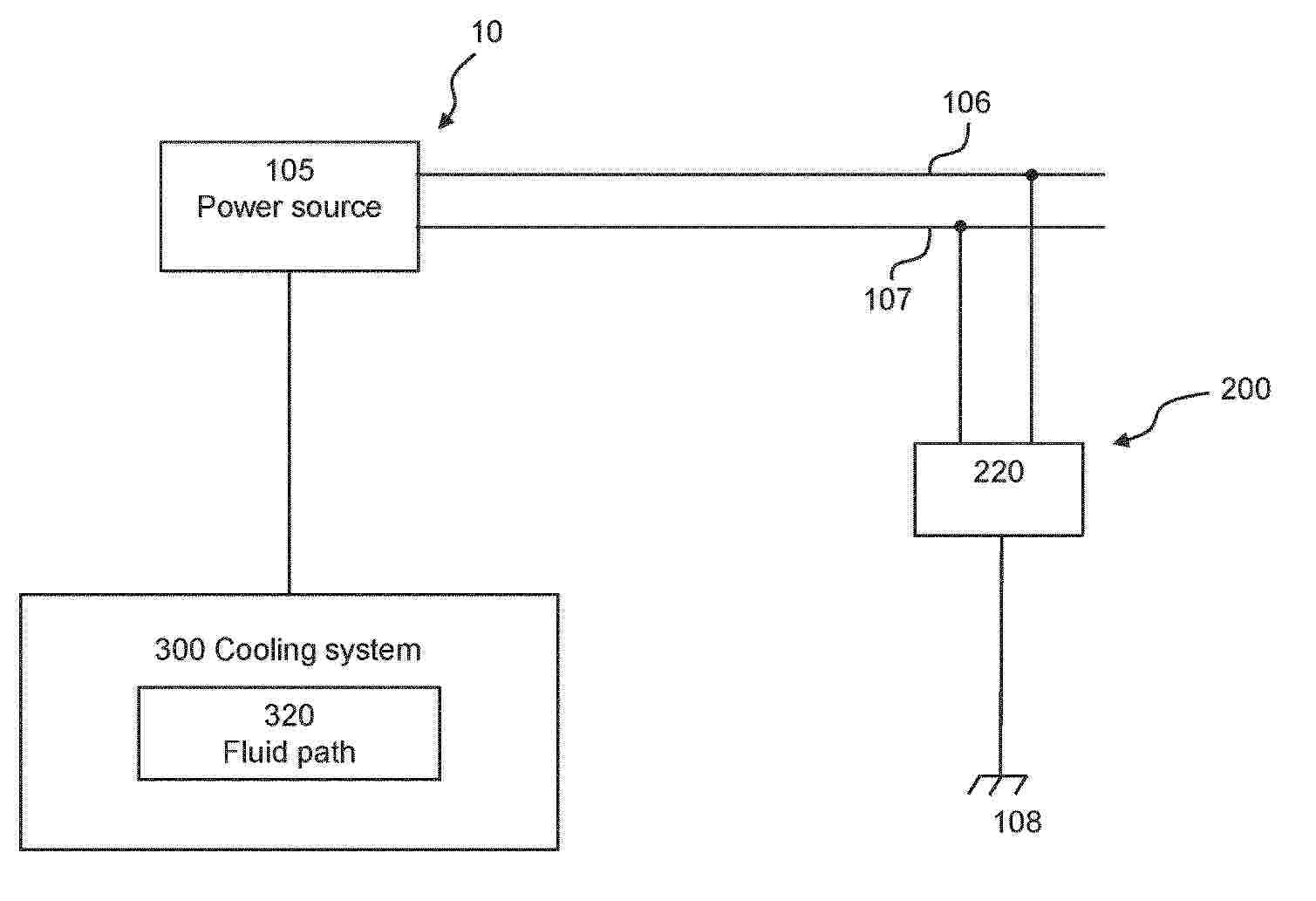
Resumen de: EP4759609A1
Computer system comprising processing circuitry configured to obtain first isolation resistance data associated with an isolation resistance between poles of a vehicle subsystem of a vehicle and a ground connection wherein a fluid path of a cooling system configured to cool the vehicle subsystem is in a first state, obtain second isolation resistance data associated with an isolation resistance between the poles and the ground connection wherein the fluid path is in a second state, where the coolant in the fluid path is electrically energized at least in the second state and determine a change in isolation resistance.
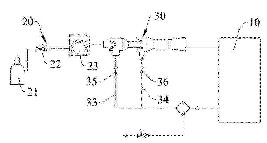
Resumen de: CN122224880A
本申请涉及航空燃料电池氢气循环技术领域,具体而言,涉及一种航空燃料电池氢气引射循环分配系统及控制方法。系统包括燃料电池电堆、供氢组件、引射组件;供氢组件由依次连通的氢气源模块、减压阀、氢喷阀组成;引射组件含第一引射器、第二引射器、两路回流管及对应控制阀;第一引射器设有第一引射管、第一进气管与第一引射口;第二引射器设有第二引射管、第二进气管与第二引射口;第一引射管出口连通第二进气管,第二引射管出口接燃料电池电堆氢气入口;电堆氢气出口分别经带第一控制阀的第一回流管、带第二控制阀的第二回流管,对应连通第一引射口、第二引射口;从而解决氢气引射器无法满足航空燃料电池高稳定、高可靠的使用需求的问题。
Resumen de: CN122211208A
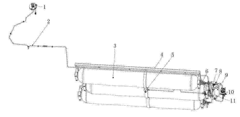
本发明公开了一种车载氢系统和燃料电池汽车,包括氢系统框架、容纳腔、减压阀以及多个储氢瓶;储氢瓶的两端分别设有连接端,氢系统框架上设有连接板,连接端与连接板分别对应连接;位于中部的储氢瓶的瓶口处设有瓶口TPRD,位于边侧的储氢瓶的瓶口通过接头和高压管路与瓶口TPRD连接,瓶口TPRD还与容纳腔连接,容纳腔的瓶口通过高压管路与减压阀连接,且容纳腔的瓶口处设有瓶阀,以控制容纳腔与减压阀之间的连通,减压阀将高压氢气减压至燃料电池所需要的压力并供给至燃料电池系统。本发明满足安全法规的基础上,可以实现减少瓶阀及TPRD的数量,有效简化布局,提升装配效率及降低成本的作用。
Resumen de: CN122224874A
本发明公开了一种汽车燃料电池双极板组件的极板密封装置,涉及密封装置技术领域,包括双极板本体和MEA边框,所述双极板本体上方设置有MEA边框,所述双极板本体上安装有支撑组件,所述支撑组件用于实现上密封结构、下密封机构位置的锁定和二次紧固密封作用。该汽车燃料电池双极板组件的极板密封装置,通过在下密封机构中设置波浪型底垫、溢流槽和弹性膜片,波浪型底垫的波浪形凹槽可实现胶水的临时储存,当胶水过量时,下压作用力可推动膜片偏转,使多余胶水进入溢流槽内,有效解决了传统密封件组装时胶水外溢的技术难题,同时,波浪型底垫上的缺口槽增加了与胶水的接触面积,确保胶水凝固后密封件与双极板本体之间连接的稳定性。
Resumen de: WO2025105390A1
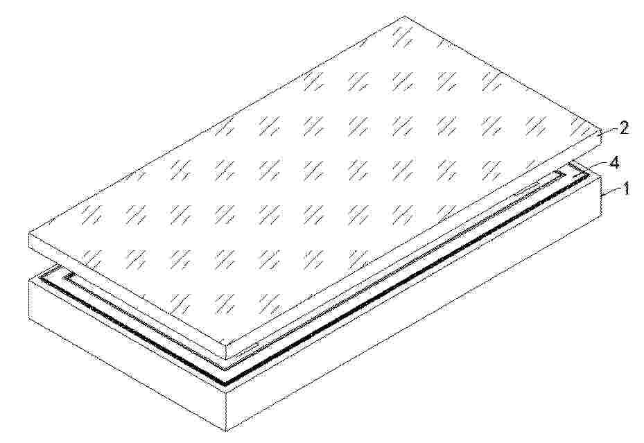
Provided is a catalyst coated electrolyte membrane which has a low voltage in an anion exchange membrane-type water electrolysis test, has excellent water electrolysis performance, and has extremely high durability to such an extent that there is no problem even when used in the AEMWE method. A catalyst coated electrolyte membrane (100) has: (A) an electrolyte membrane (11) having a rupture point stress of 85 MPa or more; and (B) catalyst layers (12, 13).
Resumen de: WO2025105224A1
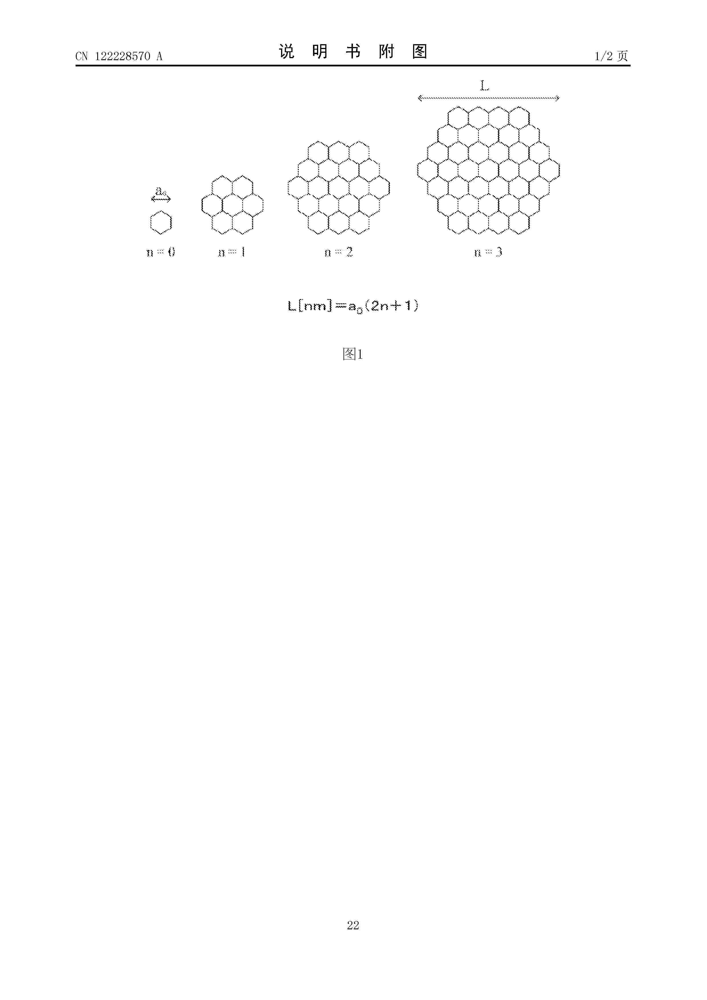
The present invention provides: a carbon catalyst which has both high catalytic activity and high durability; an electrode; and a battery. The carbon catalyst has an L/La ratio of 18 or more, the L/La ratio being the ratio of the average carbon mesh surface size L, which is obtained by programmed-temperature desorption analysis in which the temperature can be increased to 1600°C, to the crystallite size La, which is obtained from a diffraction peak near a diffraction angle (2θ) of 43° in an X-ray diffraction pattern obtained by means of powder X-ray diffraction using a CuKα ray, and a ratio of the halogen atom concentration (atom%) to the carbon atom concentration (atom%) of 0.0005 or more as obtained by X-ray photoelectron spectroscopy.
Resumen de: WO2025103713A1
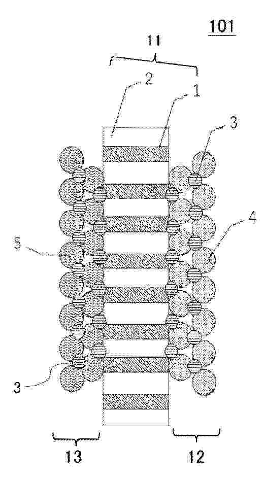
The invention relates to a membrane electrode assembly (MEA) comprising a membrane (4) arranged between two electrodes and made of a polymer ion-conducting material, and a flat sealing element (5) surrounding an outer peripheral edge and embedded in the membrane (4) at least in an edge region, wherein the sealing element (5) is designed such that it is anchored in the membrane (4) by means of an integral bond. Furthermore, a method for manufacturing such an MEA (10) is described.
Resumen de: CN122224864A
本发明涉及燃料电池领域,尤其涉及一种合金催化剂及其制备方法、应用。所述催化剂包括活性组分和载体,所述活性组分为铂与过渡金属形成的PtM合金颗粒,所述载体为部分石墨化的介孔碳,所述PtM合金纳米颗粒担载在部分石墨化的介孔碳的外表面及介孔中;所述部分石墨化的介孔碳的平均孔径为3‑10nm。本发明采用一步热处理,在过渡金属元素的作用下,实现低温催化石墨化,降低了石墨化催化剂的制备难度,同时依旧有效具备高稳定、耐久性以及高活性的优势,可以应用于80‑120℃中高温燃料电池或者水电解池。
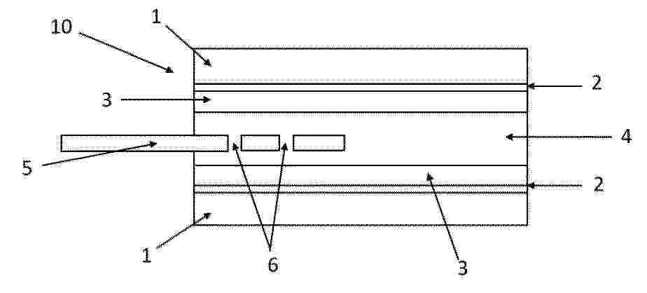
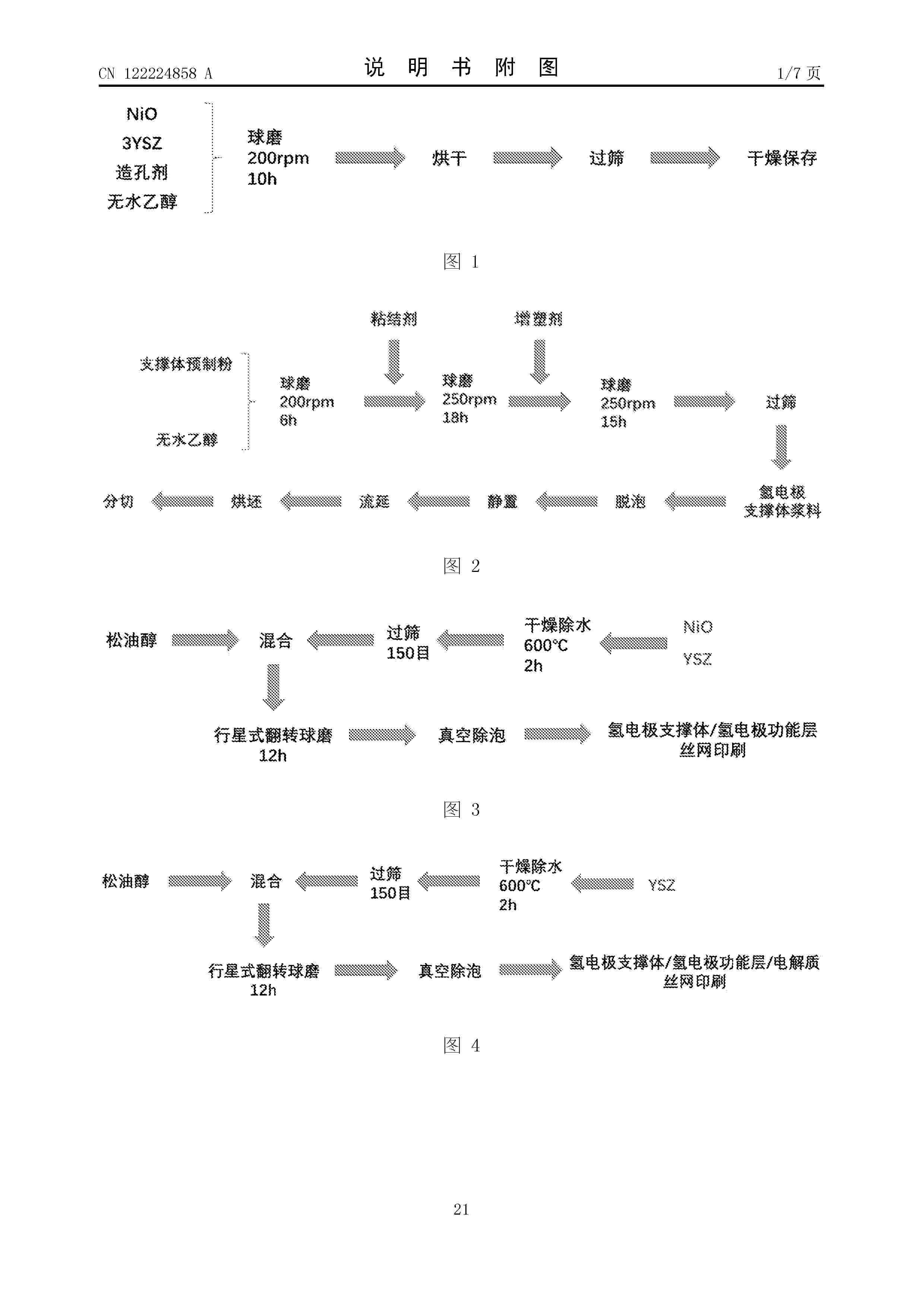
Resumen de: CN122224858A
本发明提供了氢电极支撑体在制备SOEC的单体电池片中的应用;所述氢电极支撑体,按原料计,包括:氧化镍、氧化钇稳定氧化锆、造孔剂石墨、粘结剂、增塑剂和溶剂。本发明还提供了工艺稳定的大尺寸单体电池片制备方法,提升了支撑体结构完整性,消除内部孔隙、微裂纹等缺陷,增强电池片力学强度与气密性;改进了电极与电解质层的涂覆工艺及浆料分散性,实现大尺寸基底上各功能层的厚度精准控制,促进活性物质均匀分散,保障电池片不同区域电导率、催化活性的一致性,提升整体电解性能稳定性;适配各功能层的有机载体成分与烧结收缩特性,释放热应力,减少层间剥离、翘曲变形等界面缺陷,强化各功能层间的结合强度,延长电池使用寿命。
Resumen de: CN122209313A
本发明公开了一种氮掺杂石墨烯复合气凝胶微球及其制备方法与应用,所述制备方法包括以下步骤:S1:配制氧化石墨烯复合分散液,所述氧化石墨烯复合分散液包括氧化石墨烯、含氮基团的小分子化合物、溶剂;S2:采用静电喷雾将所述氧化石墨烯复合分散液制成氧化石墨烯复合冰微球;S3:对所述氧化石墨烯复合冰微球进行冷冻干燥、高温碳化,获得所述氮掺杂石墨烯复合气凝胶微球。本发明能够制得具有丰富三维多孔结构、较高比表面积以及掺杂N原子的氮掺杂石墨烯复合气凝胶微球,其负载铂基催化剂后得到的催化剂能够在酸性条件下表现出优异的甲醇氧化电催化性能。
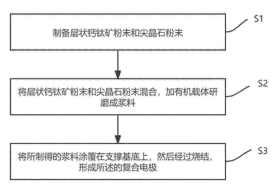
Resumen de: CN122224863A
本发明涉及固体氧化物燃料电池领域,尤其涉及一种复合电极、制备方法及其在固体氧化物燃料电池中的应用。所述复合电极,主要由层状钙钛矿和尖晶石构成;所述层状钙钛矿和尖晶石的质量比为0.5~2.0:1。本发明通过将一定质量比的高热膨胀系数的层状钙钛矿和低热膨胀系数的尖晶石复合,通过优化两者比例,能够使其热膨胀系数与电解质的热膨胀系数相匹配,从根本上消除了因热应力导致的界面分层、微裂纹等机械失效问题,显著提高了电池在热循环和长期运行过程中的结构稳定性。
Resumen de: CN122224895A
本发明公开了一种全钒液流电池多功能电解液及其制备方法和应用,属于电化学储能技术领域,方法包括:将支持电解质、硫酸氧钒和1‑(3‑氨基丙基)咪唑依次加入去离子水中,搅拌至完全溶解,得到正极电解液;将支持电解质、硫酸氧钒和硫酸肼依次加入去离子水中,搅拌至完全溶解,得到负极电解液;正极电解液和负极电解液构成全钒液流电池多功能电解液。本发明正极添加的1‑(3‑氨基丙基)咪唑,其质子化铵基能在Nafion膜表面静电阻钒,咪唑环可提升V(IV)/V(V)电对催化活性并增强热稳定性。负极添加的硫酸肼,作为强还原剂保护V(II)不被氧化,其肼基可吸附至碳毡表面形成富含催化活性的含氮官能团,提升V(II)/V(III)反应动力学并抑制析氢副反应。二者协同,全面提升电池性能与稳定性。
Resumen de: CN122224879A
本发明公开了一种无人机用氢燃料控制系统,包括氢瓶、减压阀、氢气进堆阀、第一压力传感器、燃料电池堆、汽水分离器、双变量蠕动泵、第二压力传感器、控制器、排水阀、温度传感器及电流传感器。系统构成闭式氢气循环回路以回收未反应氢气。控制器通过由双压力传感器、温度传感器和电流传感器组成的感知网络,实时监测氢气循环压力、电堆温度及负载电流,并基于内置程序分析负载变化与水热状态,从而协同调控双变量蠕动泵的转速与挤压程度,动态优化氢气循环的流量与冲刷强度。该系统解决了无人机燃料电池在动态工况下的水热管理难题,在提升氢气利用率的同时,有效防止水淹与膜干涸,保障了系统的高效、稳定与长寿命运行。
Resumen de: CN122224881A
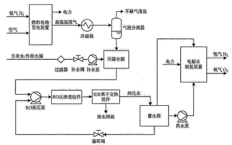
本发明属于氢能储能技术领域,公开了一种氢储能水循环回收系统和水循环智能回收方法以及应用。该系统包括燃料电池发电装置、集成了冷凝、反渗透及离子交换组件的冷凝纯化装置、蓄水箱、电解水制氢装置及智能控制器;系统特别设置了水循环回路与外部补水回路,形成双重安全保障。本发明通过建立产水与储能功率的定量模型实现蓄水容量的精准设计,并利用智能控制器基于深度学习预测工况趋势、结合强化学习算法动态优化泵送策略,实现对水质与能耗的自适应调控。本发明有效解决了氢储能系统水循环效率低、容量匹配难及长时运行稳定性差的问题,实现了水热平衡与高效回收,显著提升了系统的集成度与自动化水平。
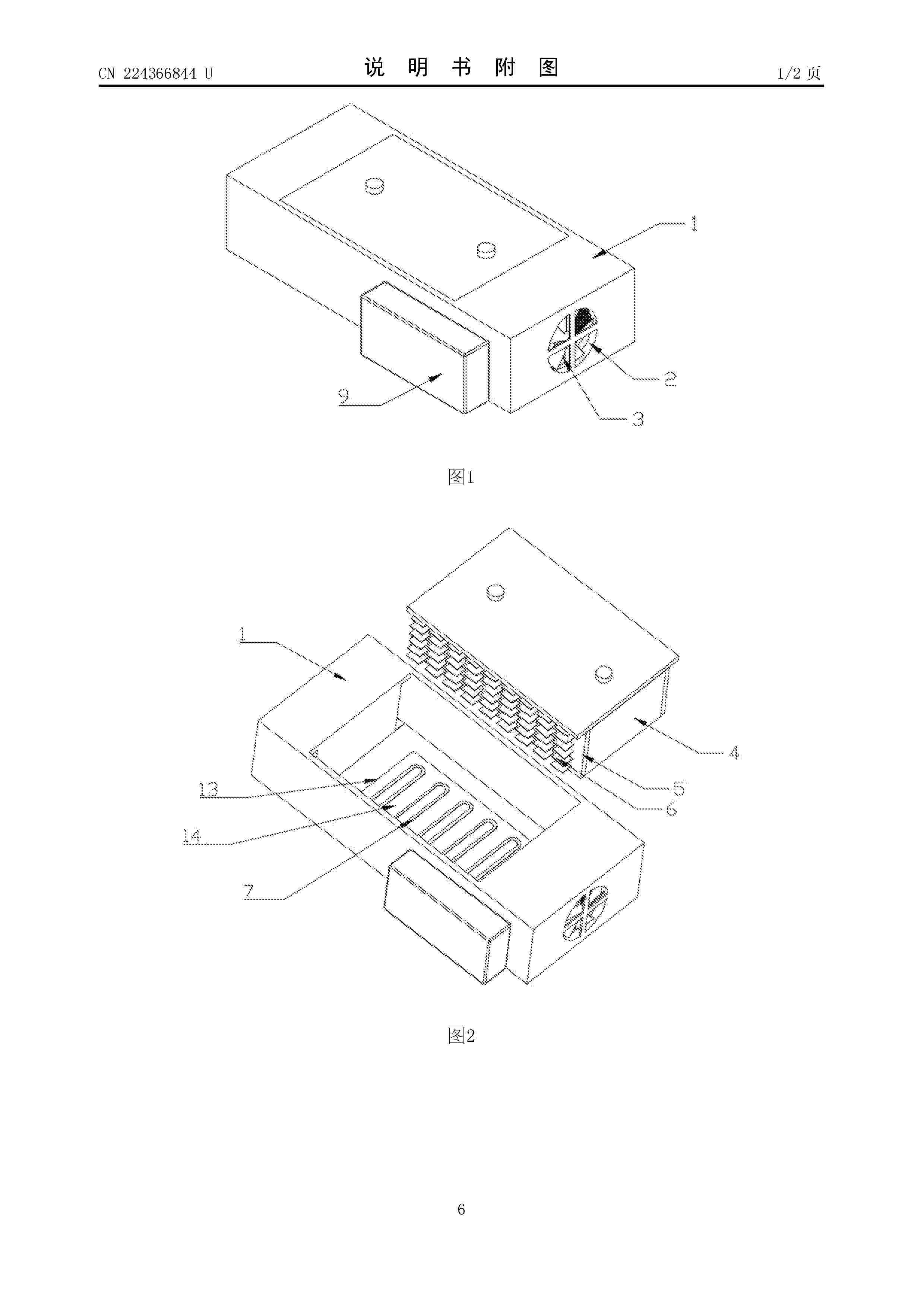
Resumen de: CN224366844U
本实用新型公开了一种氢燃料电池电堆散热器,属于氢燃料电池技术领域,包括两侧开设有通风孔的盒体,两个所述通风孔处均固定安装有风扇组件,所述盒体内部中心处固定安装有电堆本体,所述电堆本体两侧均固定贴合设有均热块,并在所述均热块背向电堆本体的一侧设有多个散热鳍片。该氢燃料电池电堆散热器,通过电堆本体两侧的均热块与散热鳍片配合风扇组件实现低负载下的风冷散热,通过水冷组件配合冷排与风扇组件,实现高负载下的水冷散热,同时,均热块与散热鳍片与冷排在同一风道内,实现高负载下的风冷辅助散热,相较现有的装置,避免了高低负载下难以保持最佳工作温度区间的问题,提高了散热器使用的灵活性。
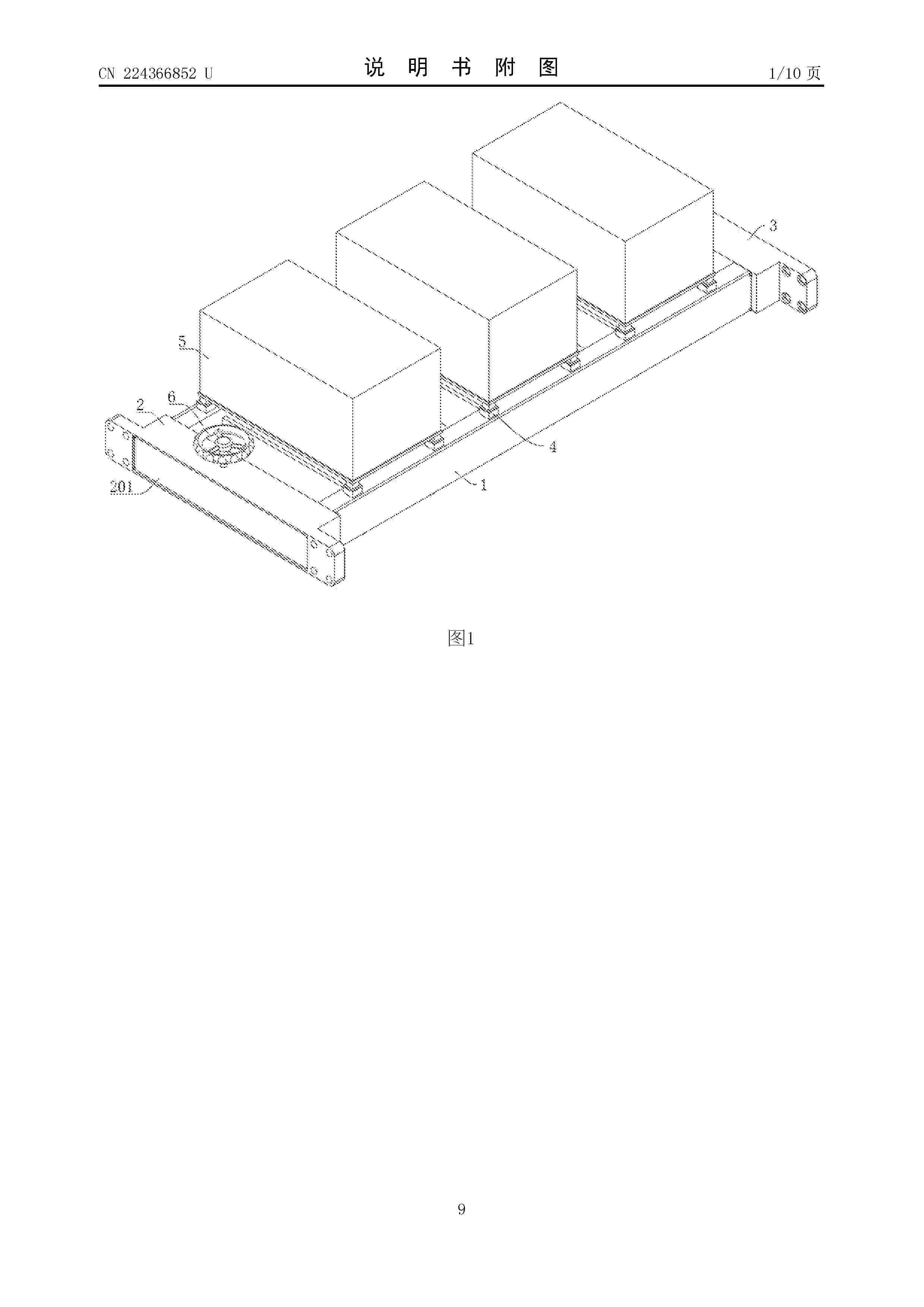
Resumen de: CN224366852U
本实用新型提供了氢能源电池安装结构,包括两个横梁以及设置于电池本体底部的插柱;插柱的侧壁上开设有嵌槽;横梁的两端分别固定有第一侧座和第二侧座;第一侧座内设置有槽体;还包括多组套筒,单组套筒用于供单个电池本体底部的插柱配合插接;多组套筒等间距固定于两个横梁上,且套筒的底端与设置于横梁内的腔体连通;第一侧座的槽体和横梁的腔体内设置有驱动机构,且驱动机构的输入端连接有手轮,手轮转动安装于第一侧座上;横梁的腔体内设置有多组压座,且多组压座均与驱动机构连接,驱动机构用于同步驱动多组压座移动,以使压座压入或离开嵌槽。其可同步进行多个电池本体的锁定和解锁,安装操作便捷,有效提高电池本体的安装和拆卸效率。
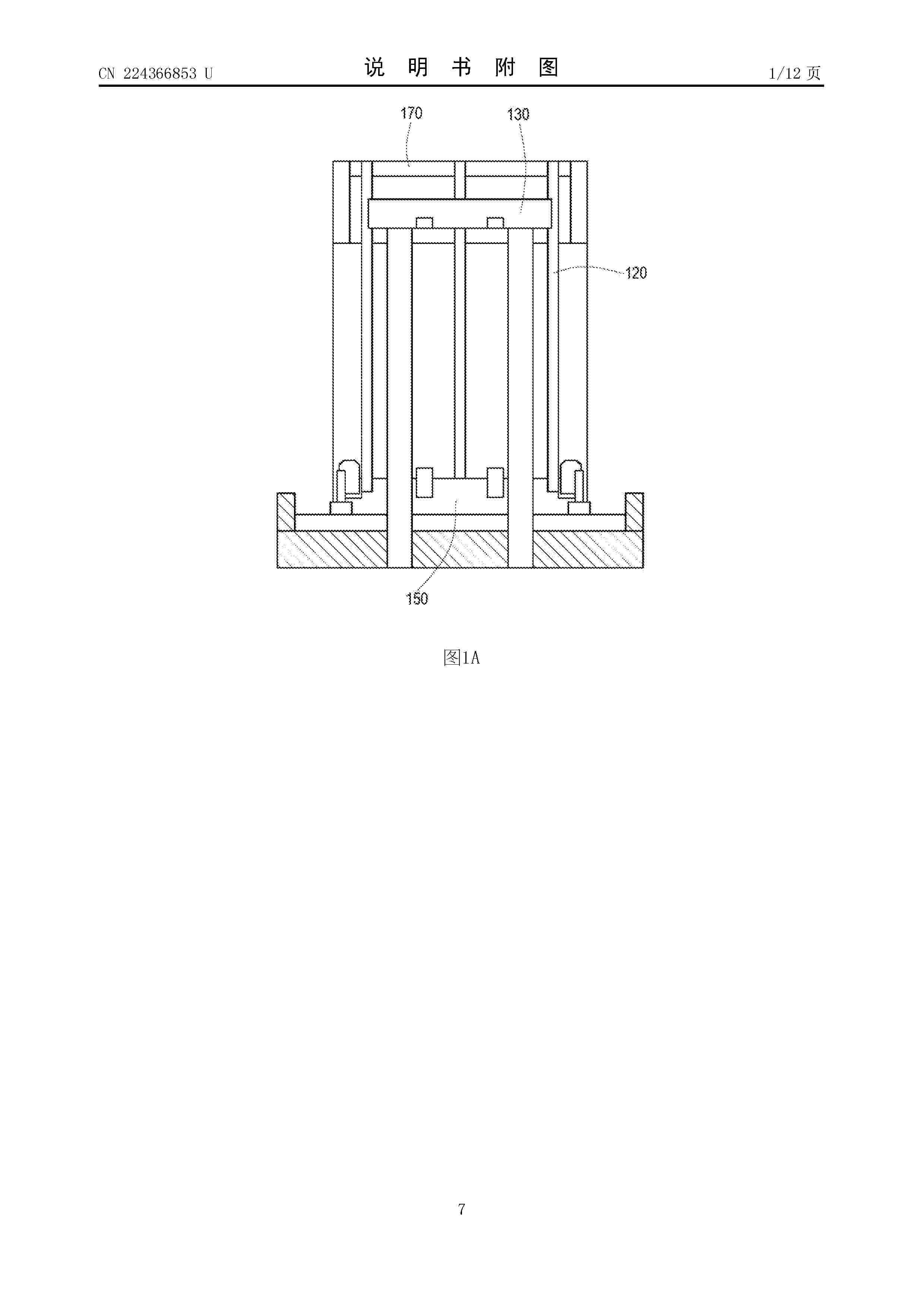
Resumen de: CN224366853U
本实用新型提供一种燃料电池结构,可提高燃料电池组的组装精度且可抑制电池变形。燃料电池结构包括:燃料电池组,包括相互堆叠的多个电池,当沿所述多个电池的堆叠方向观察时,所述多个电池中的每一者的外缘具有凹槽;以及杆状的延伸轴,沿所述堆叠方向延伸,所述延伸轴设置在对应于所述凹槽的位置,当沿垂直于所述延伸轴的轴向的至少一方向观察时,所述延伸轴的端部的形状沿着往所述端部的末端的方向逐渐变细,所述凹槽的内缘包括多个直线部,所述端部具有锥形接触平面。
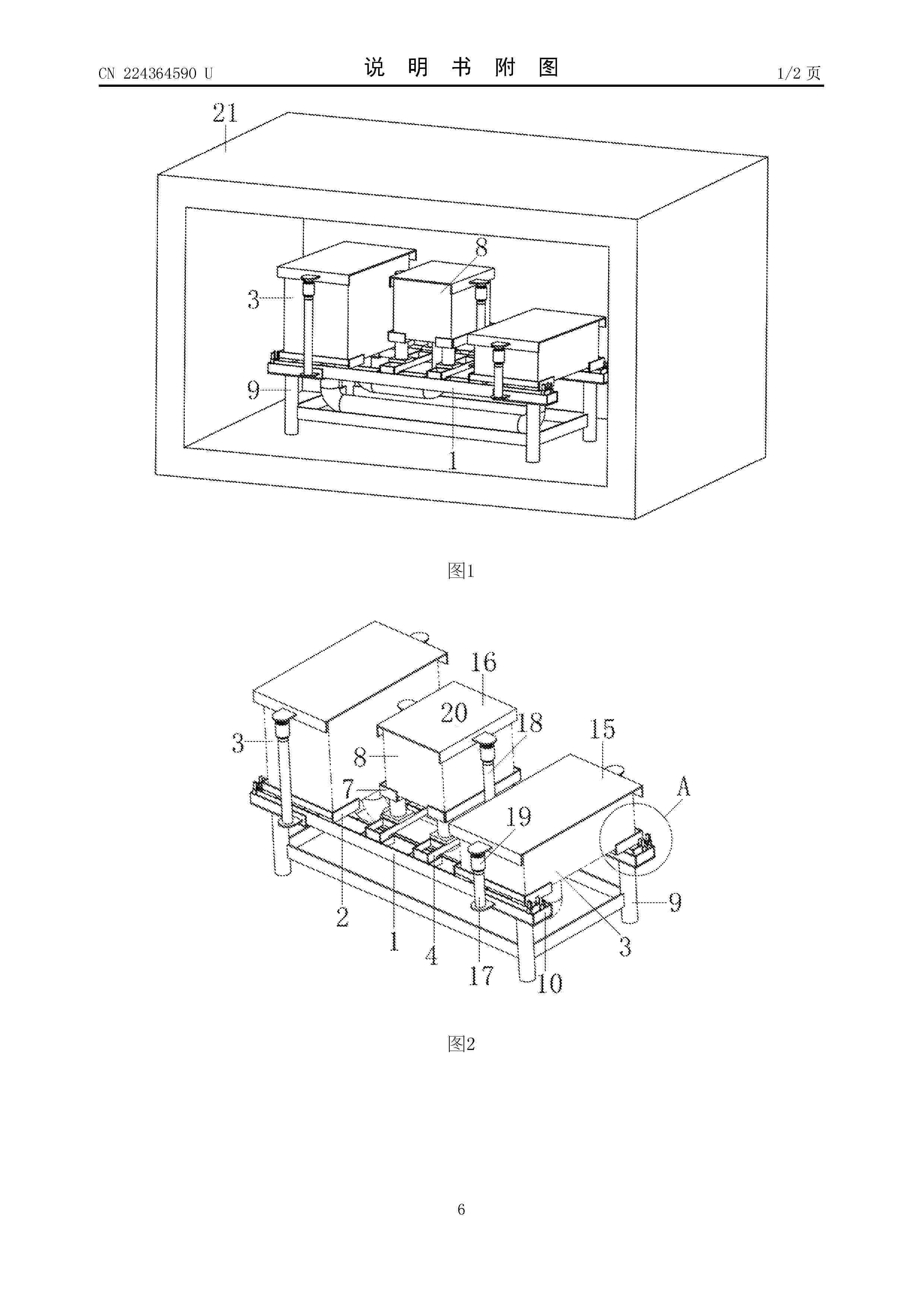
Resumen de: CN224364590U
本实用新型涉及一种用于高温环境的自调节支撑装置,包括相对设置的两个第一支撑梁,第一支撑梁的顶部设有第一限位槽,一号设备底部的相对两侧分别放置在两个第一限位槽上,第一限位槽的内壁与一号设备之间设有间隙,两个第一支撑梁之间设有相对设置的两个第二支撑梁,第一支撑梁的顶部设有若干卡槽,第二支撑梁的底部设有与卡槽卡接的卡块,第二支撑梁的顶部设有第二限位槽,二号设备底部的相对两侧分别放置在两个第二限位槽上,卡槽的内壁与卡块之间设有间隙,第二限位槽的内壁与二号设备之间设有间隙,第一支撑梁底部的两端均设有支撑脚;本实用新型允许设备和支撑装置在产生热膨胀位移情况下自动调节位置,避免产生较大的热膨胀应力。
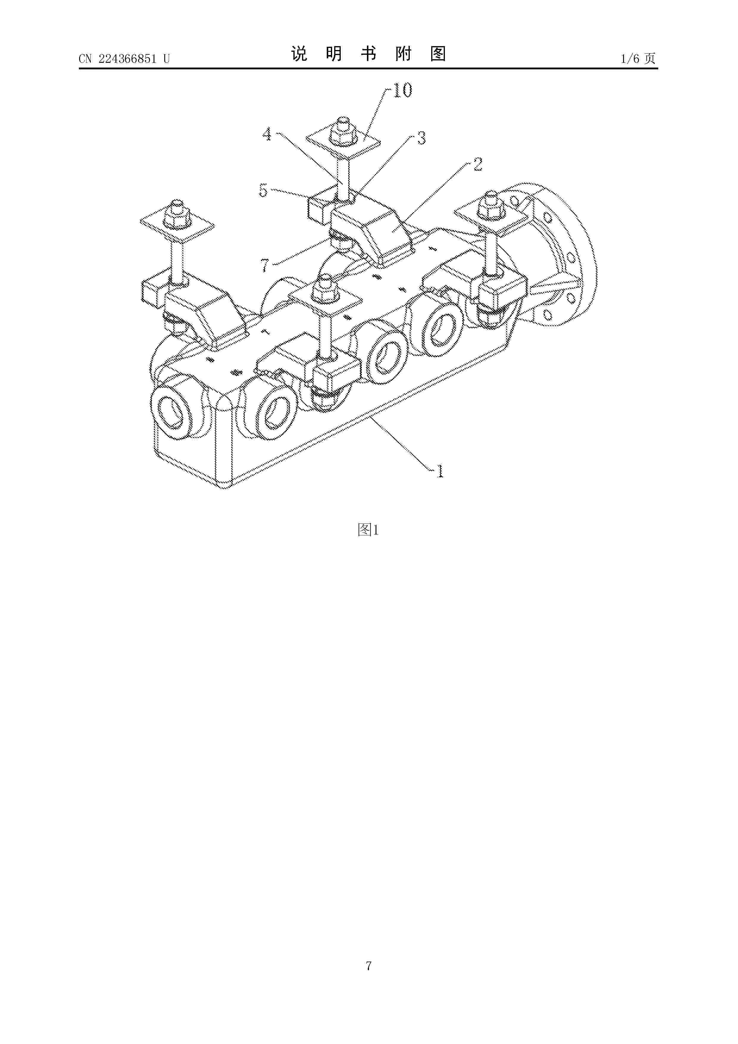
Resumen de: CN224366851U
本实用新型属于液流电池储能技术领域,具体为一种液流储能分配器总成,包括分配器,所述分配器由相同材料的分流箱和连接头组成,所述分流箱通过吹塑成型且具有数个支流接头与支管道连接,所述连接头通过注塑成型,所述连接头包括直管与分流箱热熔焊接,还包括法兰与主管道连接,所述分流箱上端成型有若干吊耳;本实用新型采用吹塑成型制造分流箱结合注塑成型连接头的工艺方案:吹塑确保分流箱壁厚均匀、轻量化且适合量产,注塑保证连接头结构精度防漏液,分体制造显著降低模具复杂度与成本。
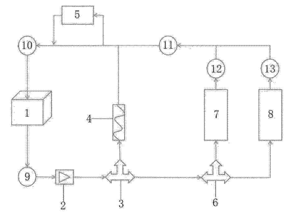
Resumen de: CN122224883A
本发明涉及一种燃料电池重卡发动机热管理系统及冷启动控制方法,电池电堆的冷却液出口通过高温循环水泵与节温器的输入端连接;节温器依次与水热PTC、氢气加热器连接,氢气加热器与电池电堆连接,形成第一循环回路;节温器与三通阀连接后与第一散热器串联,第一散热器通过氢气加热器与电池电堆连接,形成第二循环回路;三通阀与第一散热器、第二散热器并联后,与氢气加热器串联,氢气加热器与电池电堆连接,形成第三循环回路;热管理控制器基于电池电堆的冷却液进出口水温、功率,确定节温器、三通阀开启时间和分流比例,确定流经水热PTC、第一散热器、第二散热器的冷却液流量;实现温度的平稳快速升高,缩短冷启动过程,提高了用户体验。
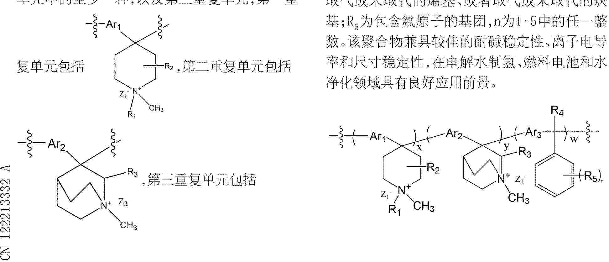
Resumen de: CN122213332A
本申请提供了一种聚合物及其制备方法、阴离子交换膜、阴离子交换离聚物溶液、膜电极和应用,所述聚合物包括第一重复单元和第二重复单元中的至少一种,以及第三重复单元;第一重复单元包括,第二重复单元包括,第三重复单元包括,其中,Ar1、Ar2、Ar3分别独立地选自芳香族多环基团,Z1‑、Z2‑表示阴离子;R1、R2、R3、R4分别独立地选自氢、取代或未取代的烷基、取代或未取代的烯基、或者取代或未取代的炔基;R5为包含氟原子的基团,n为1‑5中的任一整数。该聚合物兼具较佳的耐碱稳定性、离子电导率和尺寸稳定性,在电解水制氢、燃料电池和水净化领域具有良好应用前景。
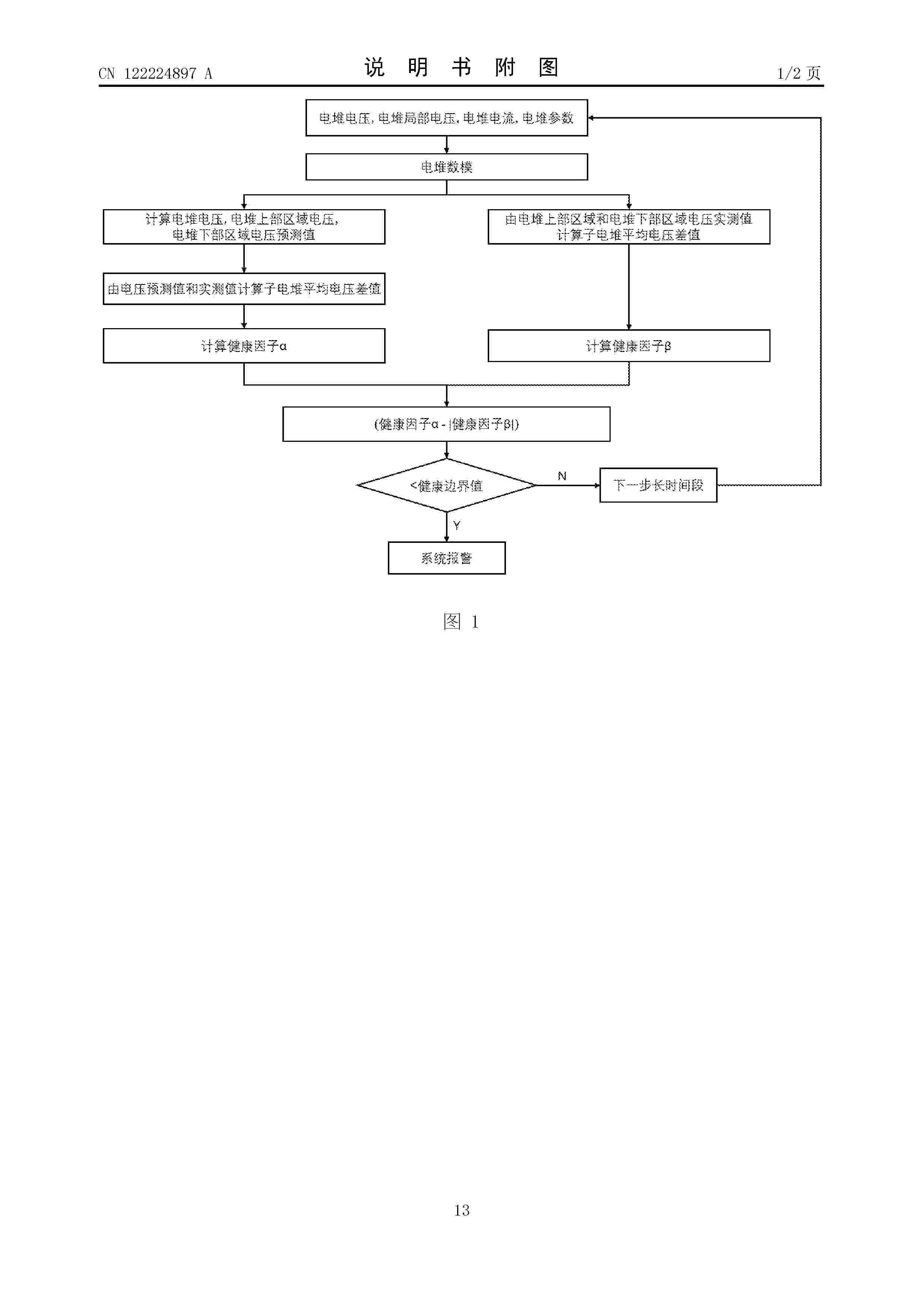
Resumen de: CN122224897A
本申请提供了一种磷酸燃料电池用电堆以及其健康检测方法,磷酸燃料电池用电堆由多个子电堆串联叠加组成,每个子电堆之间由冷却板隔开;计算磷酸燃料电池用电堆的健康因子α和健康因子β,并且健康因子α和健康因子β与健康边界值比较,实现对其健康监控。本发明不需要子电堆电压巡检监测设备,基于监控电堆整体电压和电堆局部电压,通过电堆电压以及电堆局部电压和模型预测值比较产生健康因子,实现对子电堆的健康监控,该方法可有效发现子电堆的非正常性能衰减,提供故障早期预警并采取相应电堆控制措施,避免了子电堆的失效并提高了电堆整体运行的稳定性和可靠性,同时降低了电堆的巡检和监测成本。
Nº publicación: CN224366854U 16/06/2026
Solicitante:
浙江氢源智能科技有限公司
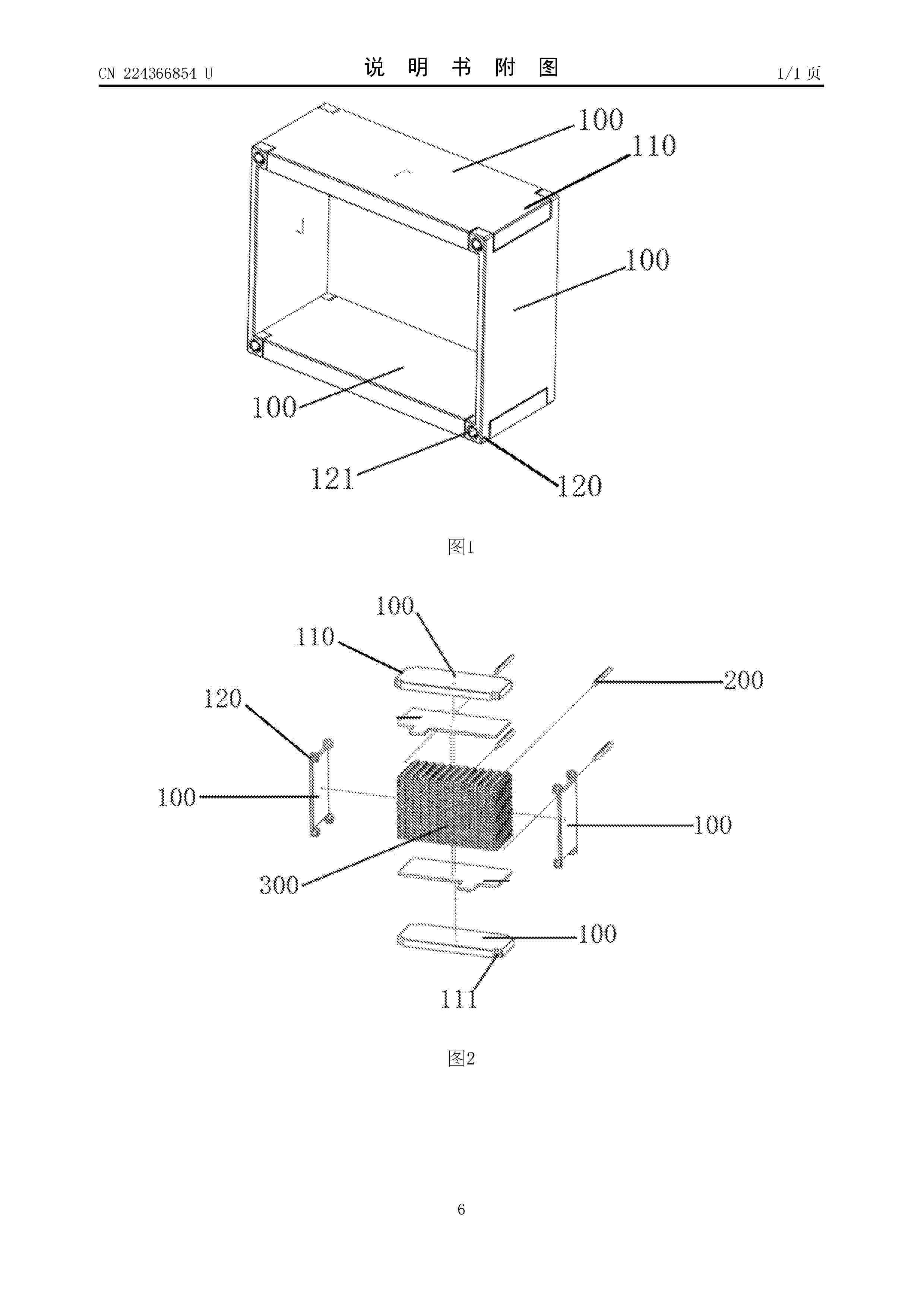
Resumen de: CN224366854U
本实用新型公开了一种氢氧燃料电池电堆固定装置,包括四块板体,各板体围合形成容纳电堆的矩形固定空间;其中两相对的板体两端设有连接端,另外两相对的板体两端对应连接端外侧设有连接头,连接头外侧设有用于固定连接端的紧固螺丝。本实用新型中的固定装置采用板体结构围合构成,使电堆能够固定在内部的固定空间内,各个板体端部通过连接端和连接头相互固定,利用紧固螺丝完全固定连接位置,使各个板体能够对电堆本体提供均匀的紧固力,确保电堆运行过程中的稳定性,具有较高的实用价值。
 BOPI
BOPI
 Sede Electrónica