Si deseas distinguir tus productos, servicios o ambos de los de otra empresa, es posible que necesites una marca o nombre comercial. Descubre qué son, en qué consiste su procedimiento de registro y qué implica.

Información sobre los plazos de presentación de solicitudes de transformación de marcas de la Unión Europea en marca nacional española. Más información


Si tienes un nuevo dispositivo, producto o procedimiento que resuelva un problema técnico o tenga una ventaja práctica, existen distintas formas de protegerlo en España y en otros países. Descubre cómo hacerlo.

¿Tu innovación reside en la estética, la ornamentación o la apariencia de tu producto? Protégela mediante un diseño industrial. Descubre qué derechos confiere el registro y cómo realizar la tramitación.

Las indicaciones geográficas protegen el nombre de un producto originario de una zona geográfica, a la cual le debe una determinada calidad, reputación u otra característica. Descubre qué son, en qué consiste su procedimiento de registro y qué beneficios conceden.

Las patentes publicadas en todo el mundo son una valiosa fuente de información científica, técnica y comercial.

Si eres emprendedor/a o una empresa y quieres potenciar y mejorar la rentabilidad de tu negocio protegiendo de forma adecuada los activos intangibles de tu organización, en este espacio encontrarás lo necesario.


 391
resultados
391
resultados
 Última actualización
28/06/2026 [06:47:00]
Última actualización
28/06/2026 [06:47:00]


 Resultados 275 a 300 de 391

Resumen de: US20260166482A1
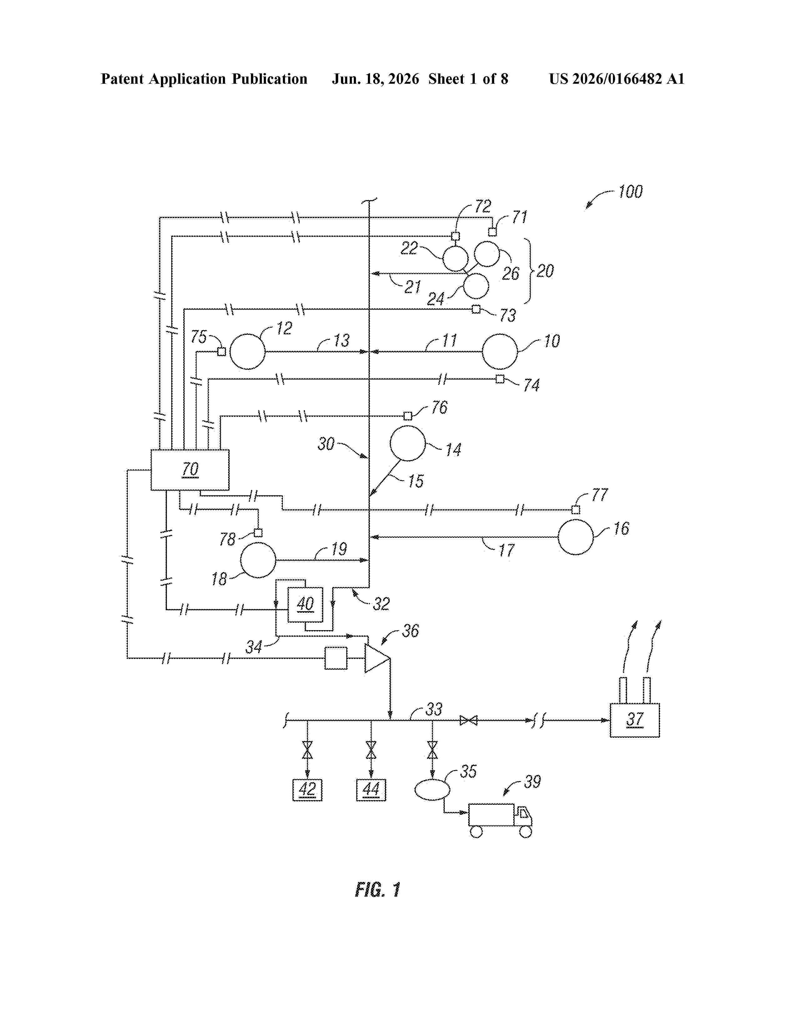
0000 A biogas collection and purification system that includes a plurality of sources of biogas and a network of conduits configured to convey the biogas from the sources to a central processing facility for processing the biogas into methane. The central processing facility removes impurities to convert biogas to biomethane and may include an H2S removal stage; an activated carbon scrubber; a gas drier; and a carbon dioxide removal stage. The facility also has a biomethane gas compressor configured to deliver the biomethane for use in power plants, for CNG production. Ancillaries to the system include fuel cells for direct electricity generation from biogas/biomethane.

Resumen de: US20260171454A1
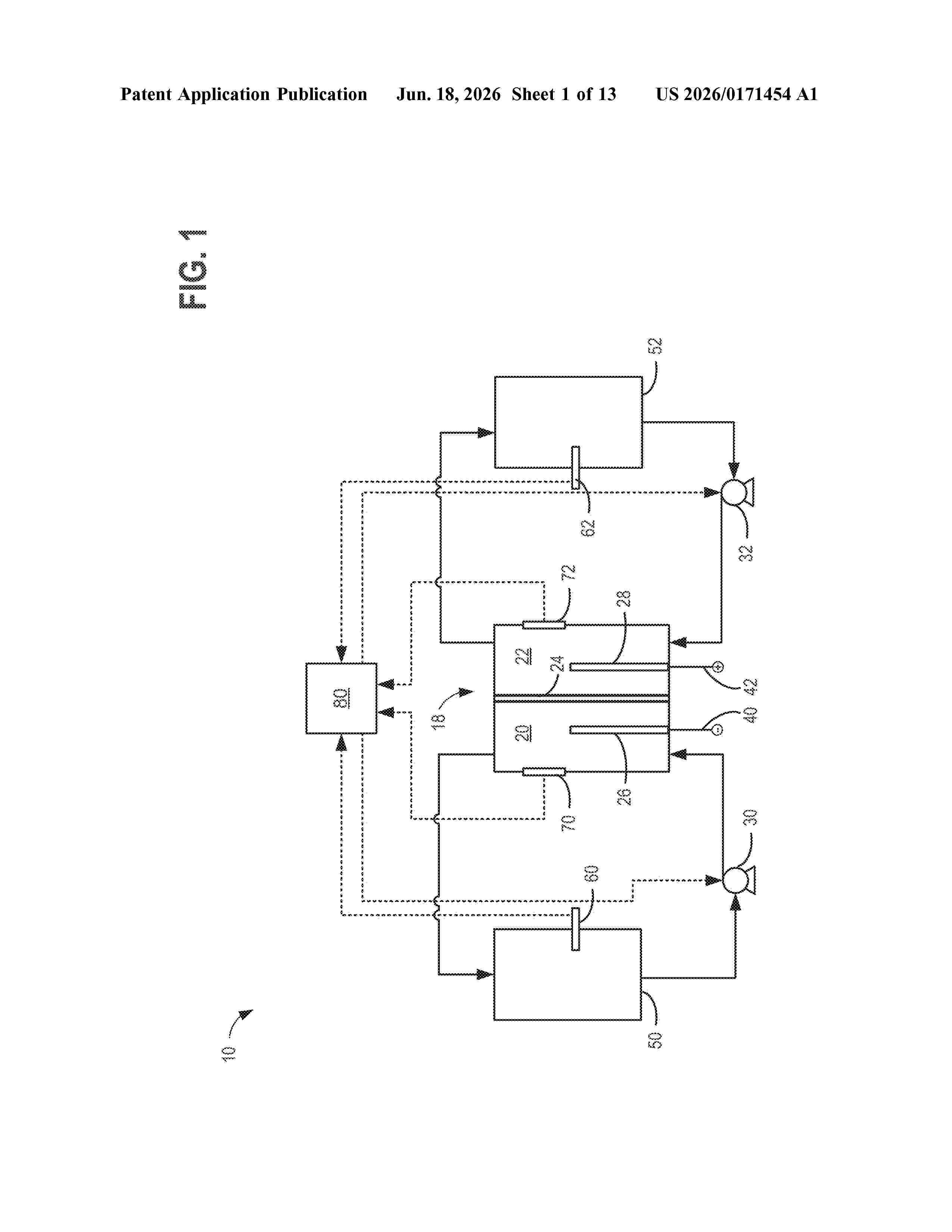
0000 A method of rebalancing electrolytes in a redox flow battery system comprises directing hydrogen gas generated on the negative side of the redox flow battery system to a catalyst surface, and fluidly contacting the hydrogen gas with an electrolyte comprising a metal ion at the catalyst surface, wherein the metal ion is chemically reduced by the hydrogen gas at the catalyst surface, and a state of charge of the electrolyte and pH of the electrolyte remain substantially balanced.
Resumen de: EP4560740A1
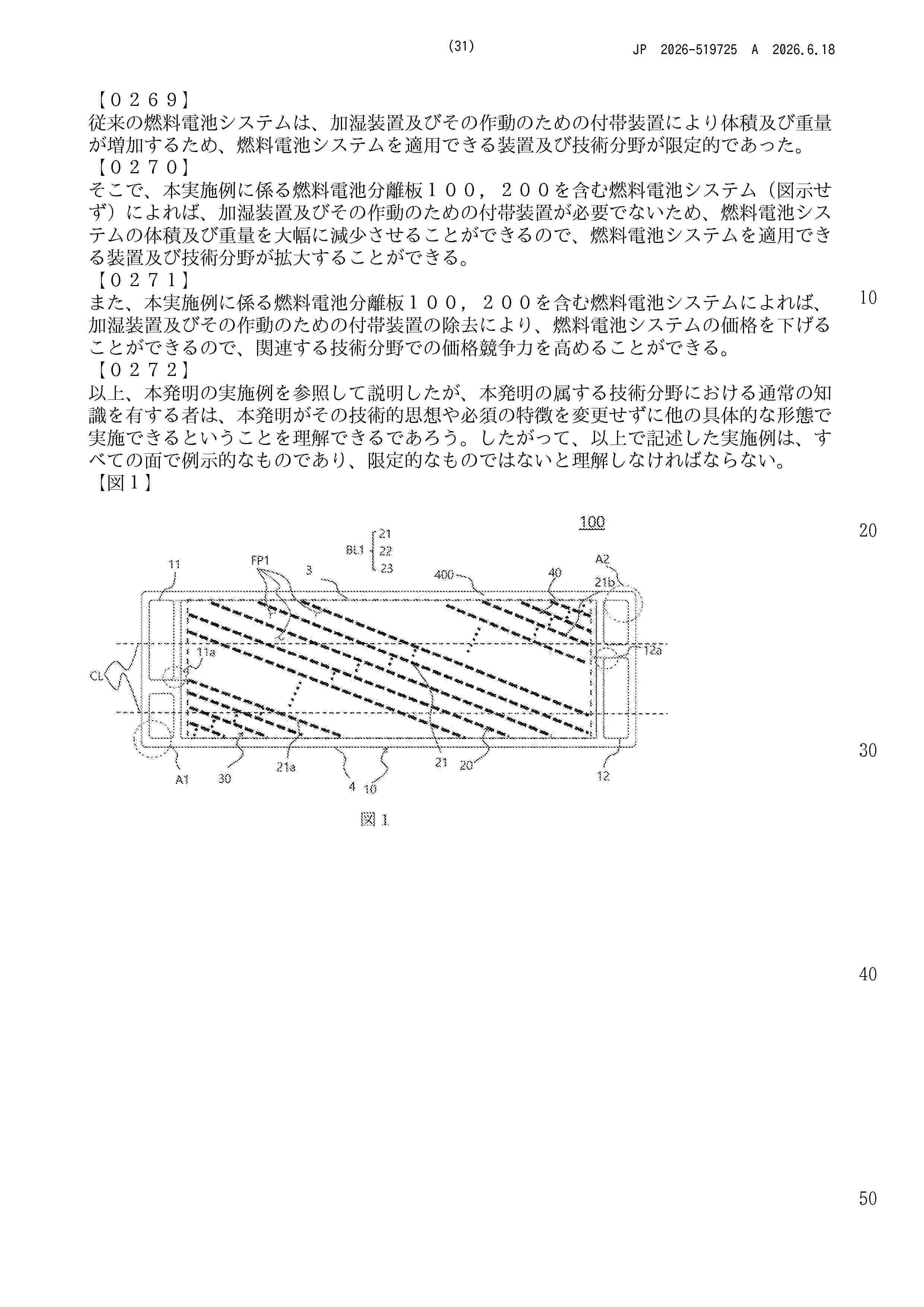
0001 The present invention relates to a fuel cell separator. More particularly, the fuel cell separator of the present invention may include a body including a gas inlet formed along a first side and a gas outlet formed along a second side facing the first side and located in the diagonal direction of the gas inlet; a first block installed in the body in a diagonal direction and configured to fluidly connect the gas inlet and the gas outlet; a second block installed adjacent to the first corner area of the first side and located on the opposite side of the gas inlet so as to be fluidly connected to the first block; and a third block installed adjacent to the second corner area of the second side and located on the opposite side of the gas outlet so as to be fluidly connected to the first block.
Resumen de: WO2026128841A2
A method and system of generating electrical power or hydrogen from thermal energy is disclosed. The method includes adding heat to (or removing heat from) a salinity gradient generator configured to generate a more concentrated and a less concentrated saline solution. The method further includes drawing the more concentrated saline solution and the less concentrated saline solution from the salinity gradient generator and feeding the more concentrated saline solution and the less concentrated saline solution into a power generator. Feeding the saline solutions into the power generator causes the power generator to receive the saline solutions and generate power by performing a controlled mixing of the more concentrated saline solution and the less concentrated saline solution. The method further includes drawing, from the power generator, a combined saline solution comprising the mixed saline solutions and feeding the combined saline solution to the salinity gradient generator.
Resumen de: US20260166463A1
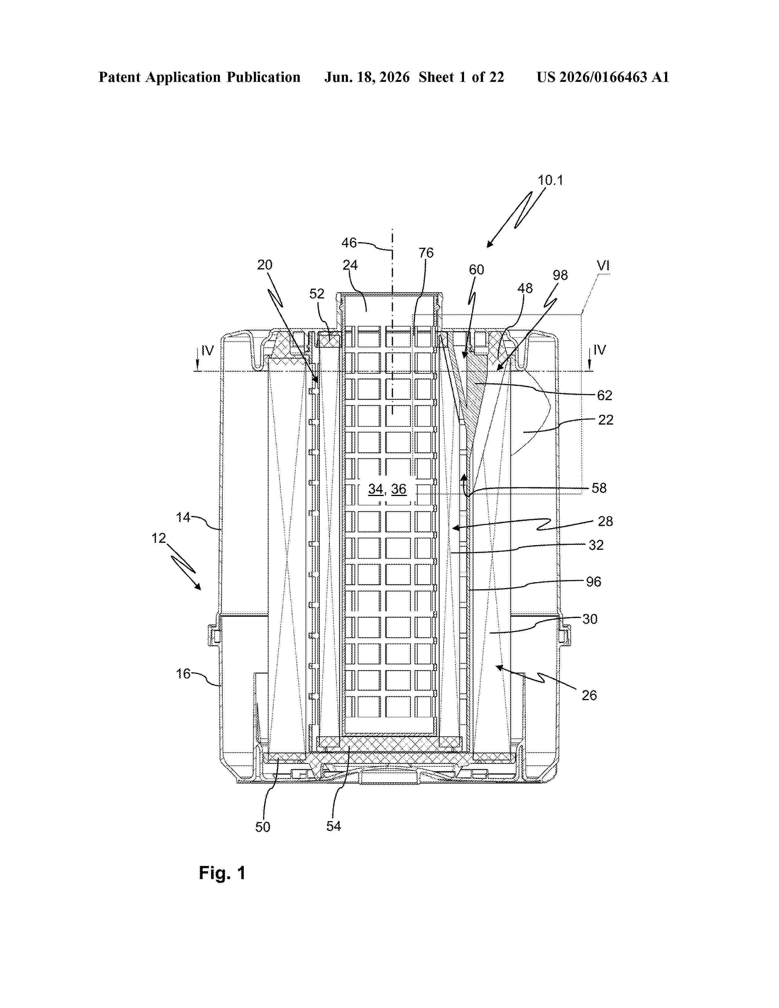
0000 A ring filter element for air filtration has a filter medium body enclosing an interior. An open end disc and a closed end disc delimit seal-tightly the filter medium body axially. The filter medium body has a folded bellows and an inner wall surface provided with a fold expansion. The open end disc has a cutout aligned with the fold expansion. A filter device has a filter housing with fluid inlet and fluid outlet. A ring filter element arrangement arranged in the filter housing separates fluid inlet from fluid outlet. The ring filter element arrangement has a ring filter element. A positioning device has an engagement element which extends radially outwardly and engages a counter engagement element of the ring filter element which is at least partially formed by the fold expansion at the inner wall surface of the filter medium body of the ring filter element.
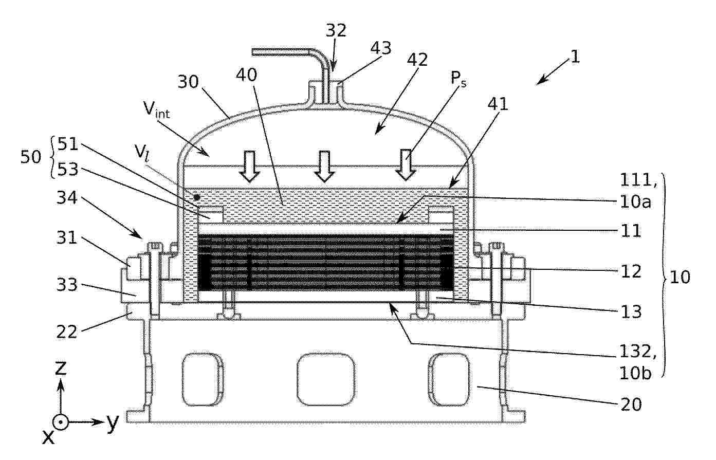
Resumen de: EP4760831A1
L'invention concerne un réacteur électrochimique (1), configuré pour recevoir un empilement (10), le réacteur comprenant une plaque d'appui (22), l'empilement étant positionné en contact avec la plaque d'appui, caractérisé en ce que le réacteur comprend en outre un dôme (30), présentant un volume interne (Vint), destiné à recevoir l'empilement, de la fritte de verre (40) liquide présentant un volume (Vl) et une face supérieure dite surface libre (41) et configurée pour recouvrir l'empilement, le volume interne comprenant en outre un gaz de couverture (42) positionné en contact de la surface libre du volume de fritte liquide, le gaz de couverture étant configuré pour être mis sous pression par un module à une pression de serrage (Ps), celle-ci étant configuré de sorte à maintenir en compression l'empilement sur la plaque d'appui sous un effort mécanique proportionnel à la pression de serrage.
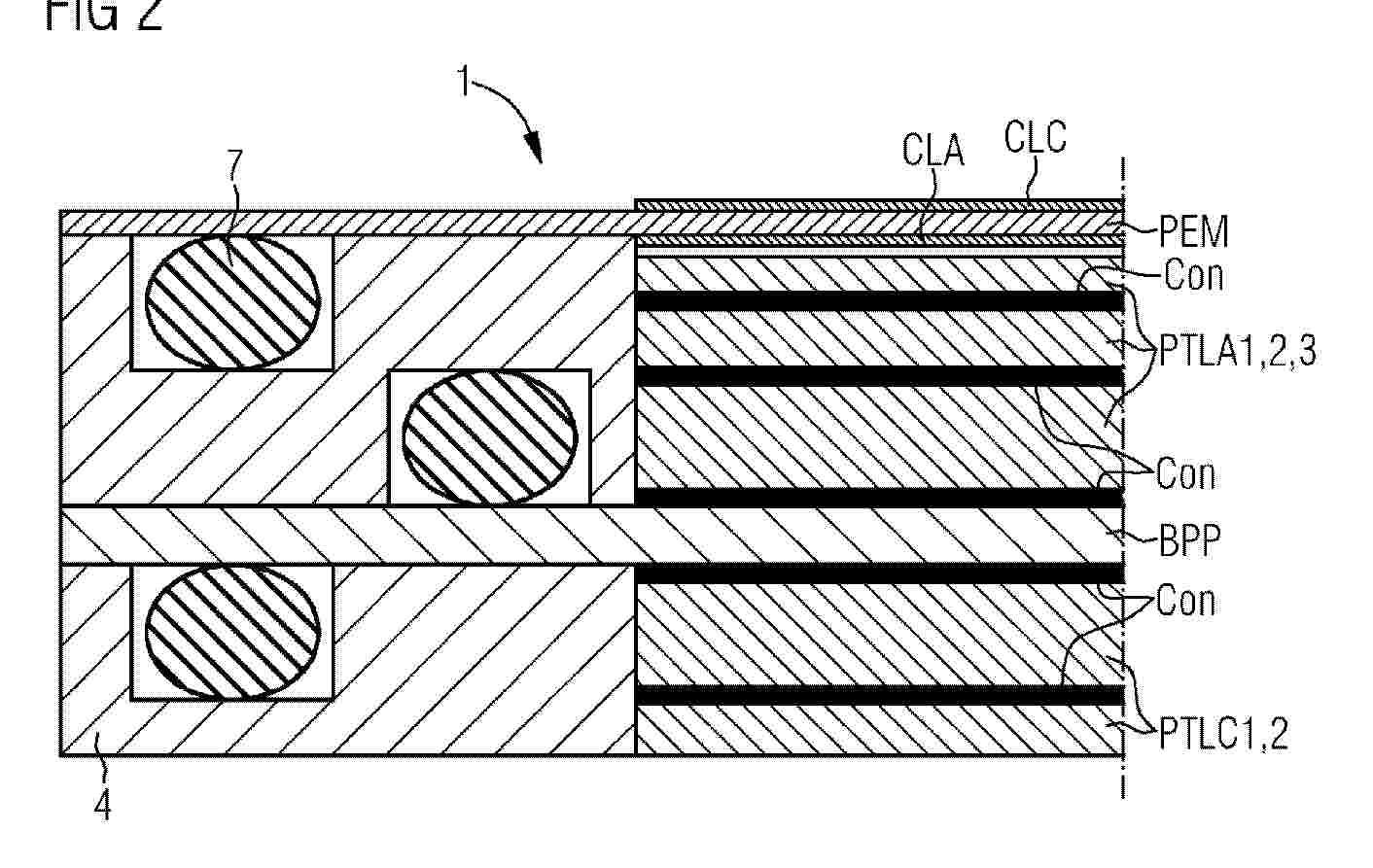
Resumen de: WO2025087586A1
The invention relates to a cell (1) for electrolysis, at least having: a layer sequence consisting of a bipolar plate (BPP), at least one cathodic gas diffusion layer (PTLC), a proton exchange membrane (PEM) between catalyst layers (CLC, CLA) or catalyst-coated membrane (CCM), at least one anodic gas diffusion layer (PTLA), which are arranged in a frame (4), wherein there is an integral bond (Con) between the individual layers of at least the BPP, PTLAC(s) and/or PTLBC(s).
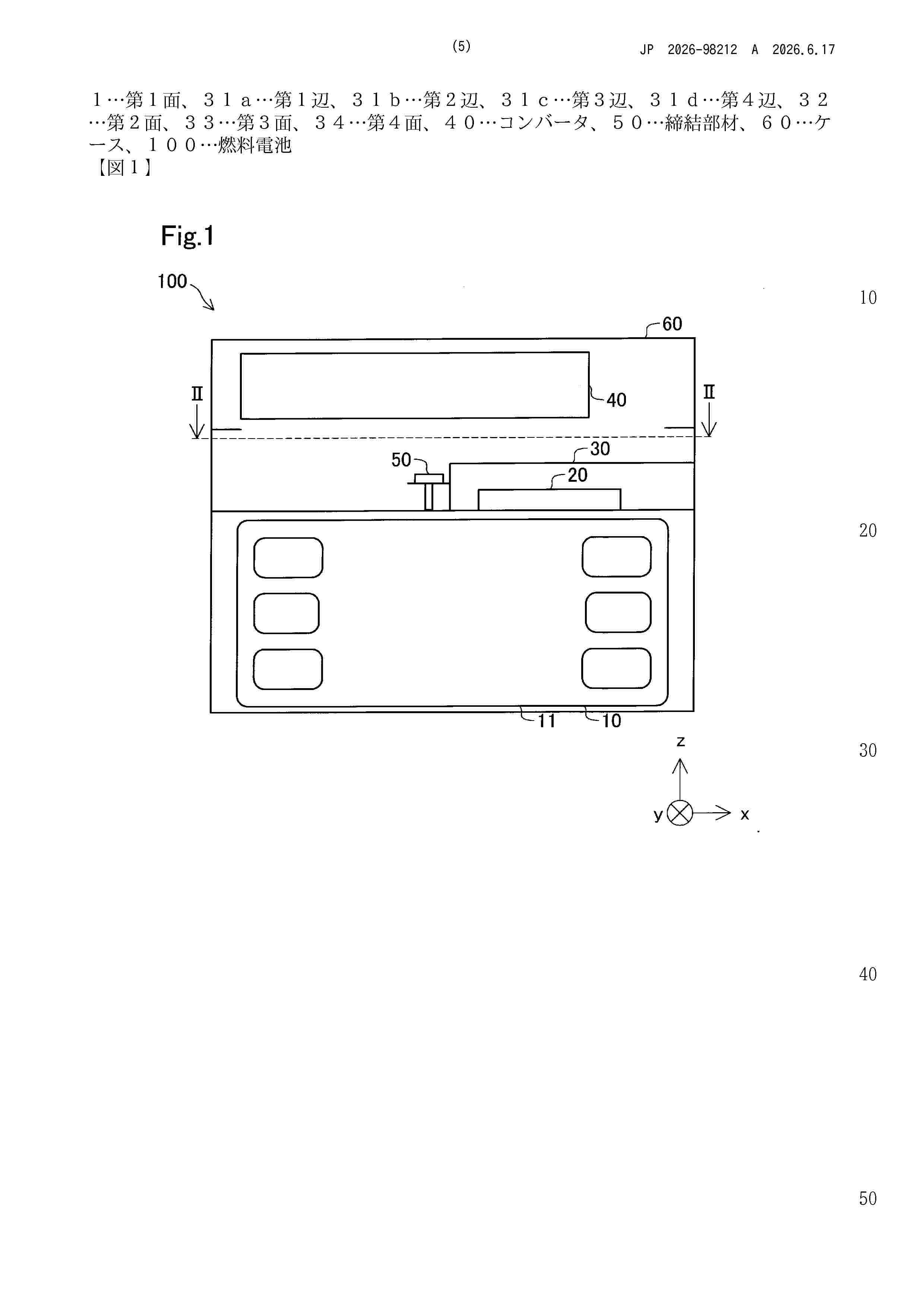
Resumen de: JP2026098212A
【課題】セルモニタを覆うカバーの放熱性能を向上できる技術を提供する。【解決手段】燃料電池は、複数の燃料電池セルが積層された燃料電池スタックと、燃料電池スタック上に配置され、燃料電池スタックの電圧と電流との少なくとも一方を検出するセルモニタと、セルモニタの少なくとも一面を覆うカバー部と、燃料電池スタックとセルモニタとカバー部とを一体的に収容するケースと、を備える。カバー部は、セルモニタと対向する第1面と、第1面と連結され、ケースの内側に面接触する第2面と、を有する。【選択図】図1
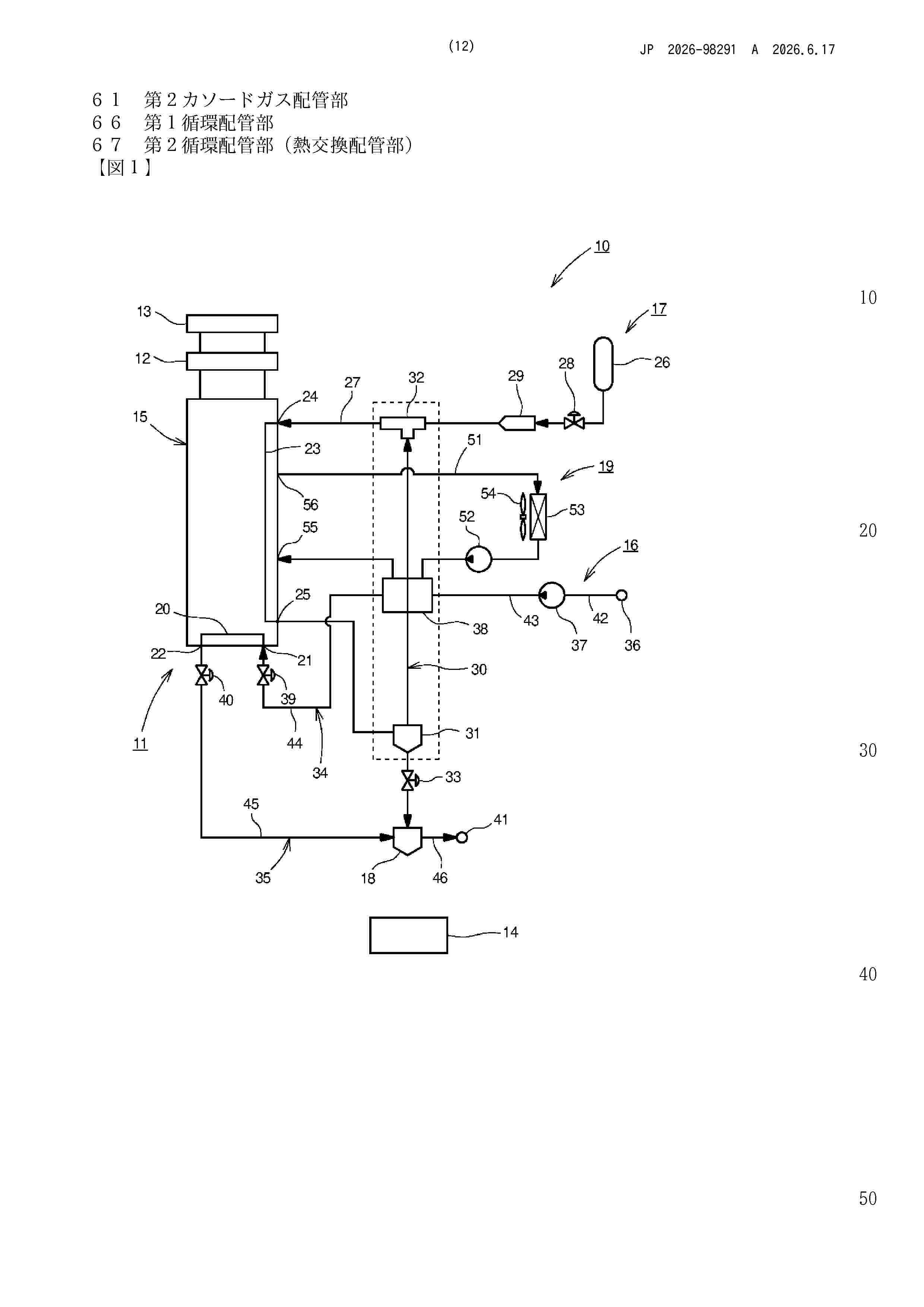
Resumen de: JP2026098291A
【課題】燃料電池スタック内への結露水の進入を可及的に低減する燃料電池システムの提供にある。【解決手段】アノードガスおよびカソードガスを反応させて電気エネルギーを生成する燃料電池スタック15と、燃料電池スタック15で使用されなかったアノードガスを含むアノードオフガスを再循環させるアノードオフガス循環路30と、アノードガス供給源から供給されるアノードガスとアノードオフガス循環路30を通じて再循環されたアノードオフガスとを混合するエジェクタ32と、カソードガスを燃料電池スタック15に供給する前に冷媒により冷却するインタークーラ38と、を有する燃料電池システム10である。アノードオフガス循環路30は、インタークーラと接触し熱伝導する熱交換配管部を有した。【選択図】 図2
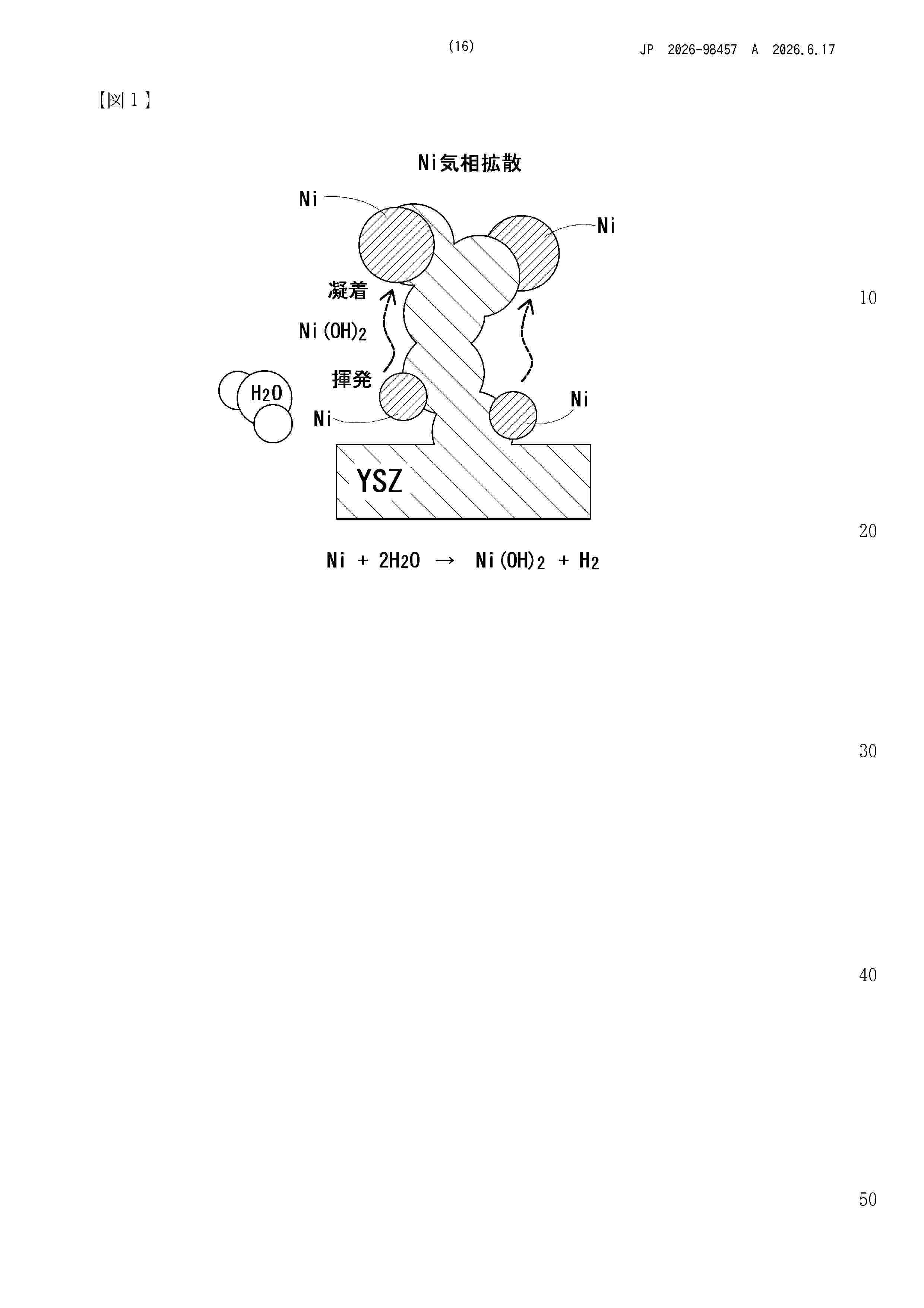
Resumen de: JP2026098457A
【課題】高温の水蒸気に曝されても電極構造の変化が少ない電極を提供すること。【解決手段】電極は、電解質粒子と、Ni系粒子とを備えている。前記電解質粒子は、La及びSmがドープされたCeO2(LSDC)を含む。前記Ni系粒子は、Ni又はNi基合金からなるコアの表面の一部又は全部がNiO又はNiを含む複合酸化物からなるシェルで被覆されたコアシェル粒子からなる。前記LSDCは、前記La及び前記Smの総含有量が0mol%超20.0mol%以下であるものが好ましい。【選択図】図6
Resumen de: GB2702429A
A power system 1100 for an aircraft includes a plurality of fuel cells having at least a first fuel cell and a second fuel cell arranged such that, in use, the first fuel cell receives a coolant 116 for cooling the first fuel cell and provides the coolant to the second fuel cell for cooling the second fuel cell. The first and second fuel cells are each arranged in use to progressively increase the temperature of the coolant. The fuel cells may be of the same type or may be of a different type. The first fuel cell may have a lower nominal operating temperature than the second fuel cell. The arrangement may further comprise a third fuel cell, wherein the third fuel cell receives the coolant from the second fuel cell. The fuel cells may comprise polymer electrolyte membrane (PEM) fuel cells. The system may comprise a coolant bleed arrangement arranged in use between the first fuel cell and the second fuel cell to bleed a proportion of the content before it is received by the second fuel cell. The coolant may be air. The coolant may be a cooling liquid, and the system further comprise a radiator arrangement. Refer to original abstract doc for image FIG. 11
Resumen de: WO2025032256A1
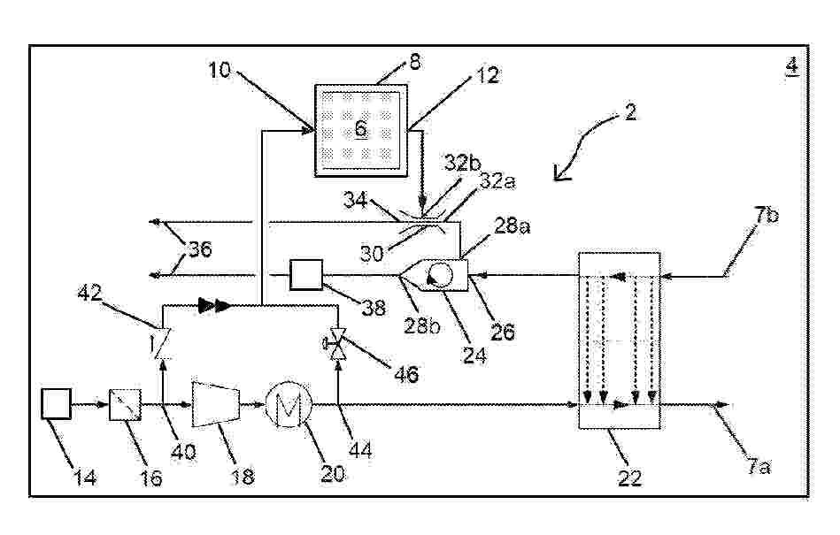
The invention relates to a fuel cell system (2), which comprises: - a fuel cell stack (6) comprising an anode and a cathode; - a housing (8), in which the stack is arranged, having a ventilation inlet (10) and a ventilation outlet (12); - a compression device (18) arranged upstream of an inlet pipe (7a) of the cathode; - a water separator (24) connected to an outlet pipe (7b) of the cathode and configured to separate an incoming cathode gas flow (26) into a first outgoing flow comprising water-rich air, exiting via a first outlet (28a) of the water separator (24), and a second outgoing flow comprising water-poor air, exiting via a second outlet (28b) of the water separator (24); - an ejector (30) comprising a primary inlet (32a) connected to the first outlet (28a) of the water separator (24) and a secondary inlet (32b) connected to the ventilation outlet (12) of the housing (8); and - a turbine (38) arranged downstream of the second outlet (28b) of the water separator (24).
Resumen de: WO2025031894A1
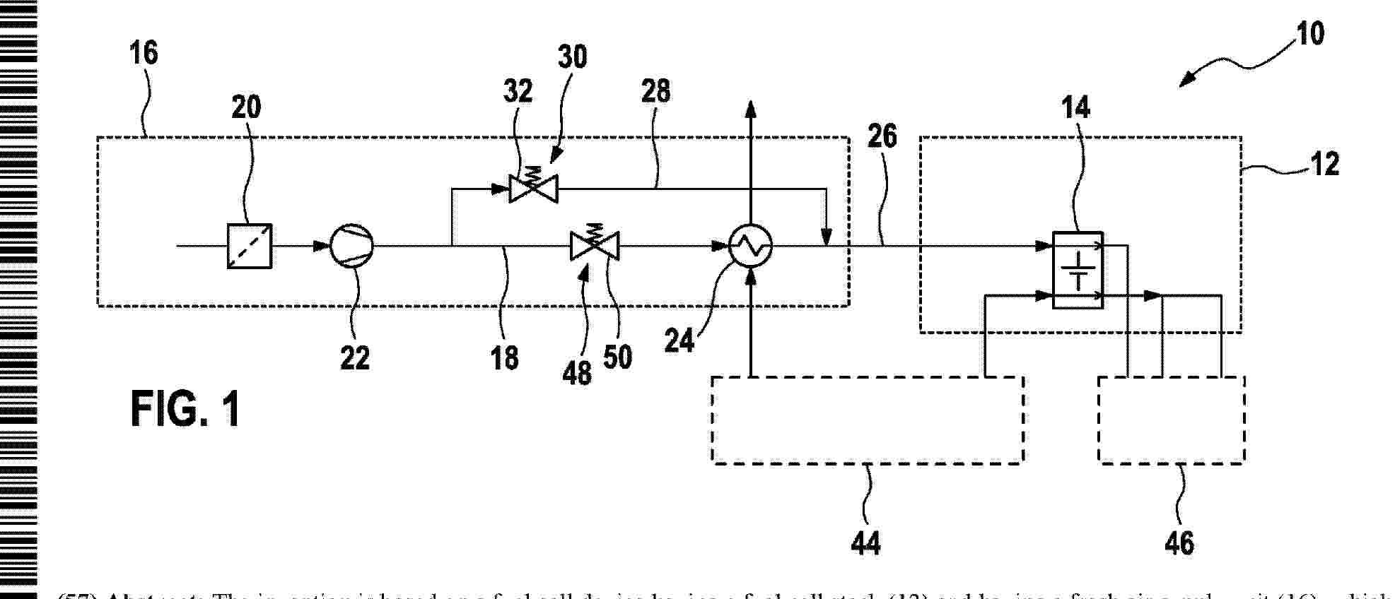
The invention is based on a fuel cell device having a fuel cell stack (12) and having a fresh air supply unit (16), which is provided for supplying the fuel cell stack (12) with fresh air, and having a heat exchanger (24) for heating the fresh air, wherein the fresh air supply unit (16) has at least a first fresh air line (18) leading through the heat exchanger (24), and a bypass line (28) leading past the heat exchanger (24), and having a flow adjustment unit (30) which is positioned in the bypass line (28) and is provided for adjusting a flow through the bypass line (28). It is proposed that the flow adjustment unit (30) has a throttle valve (32) which is provided so as, when deactivated, to move automatically into a closed position.
Resumen de: CN121713377A
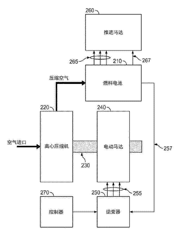
Estimation of motor rotor position includes measuring a voltage drop in the inverter during initialization of the electric motor at zero revolution per minute, and estimating a rotational speed and position of the electric motor in response to the back electromotive force and the voltage drop during increasing the rotational speed of the electric motor from zero revolution per second to a steady state rotational speed.
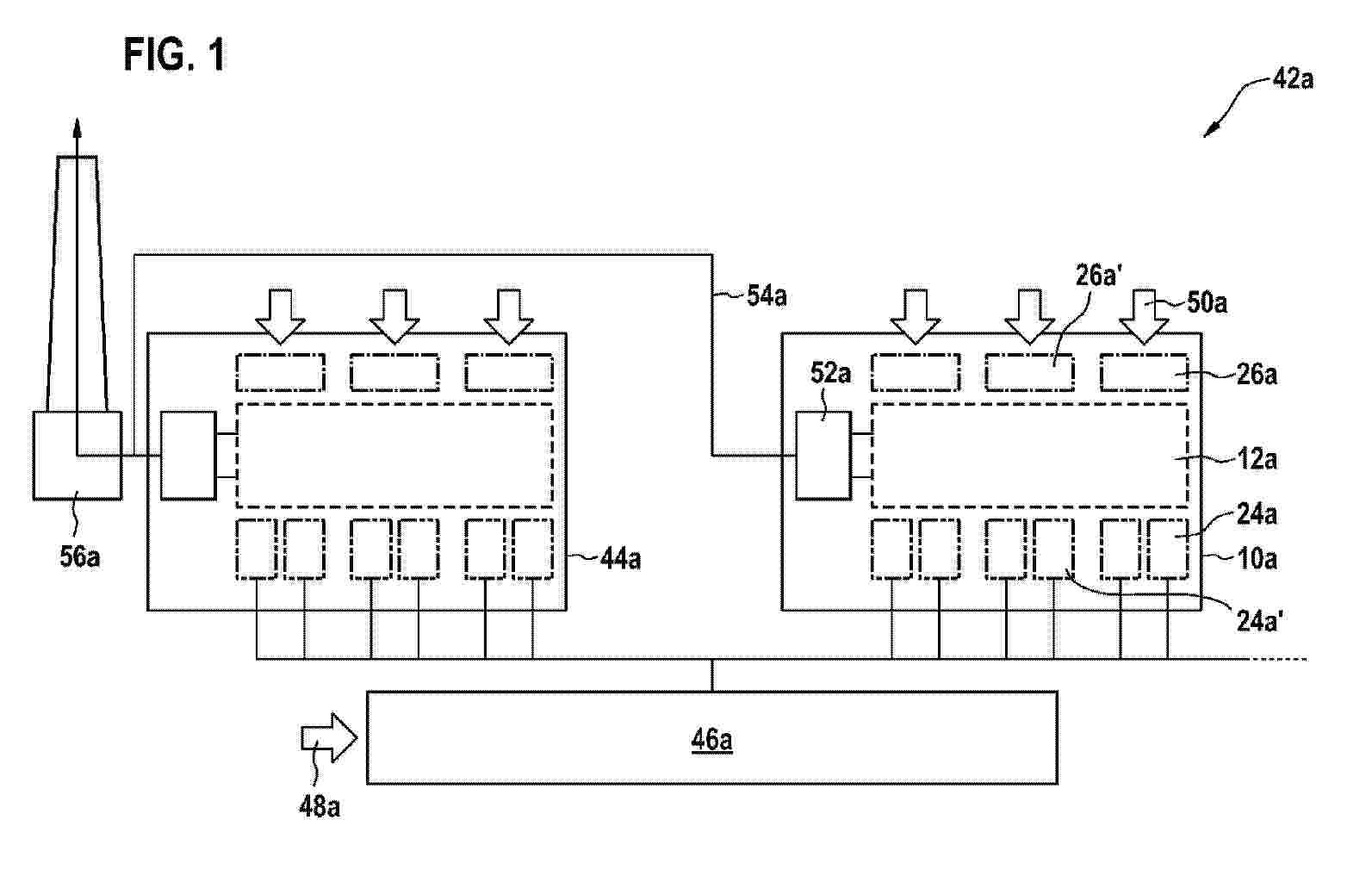
Resumen de: WO2025032151A1
The invention relates to an electrochemical device (10a; 10b; 10c; 10d; 10e) comprising at least one electrochemical module (12a; 12b, 14b; 12c; 12d; 12e) which comprises a first cell unit (16a) and at least one further cell unit (18a, 20a, 22a) for electrochemically converting at least one starting material into at least one product, and comprising at least one peripheral fluid module (24a, 26a; 24b, 26b; 24c, 26c; 24d, 26d; 24e, 26e) for supplying the starting material to the at least one electrochemical module (12a; 12b, 14b; 12c; 12d; 12e) and/or for discharging the product. It is proposed that a total number of electrochemical modules (12a; 12b, 14b; 12c; 12d; 12e) is different from a total number of peripheral fluidic modules (24a, 26a; 24b, 26b; 24c, 26c; 24d, 26d; 24e, 26e) of the same type.
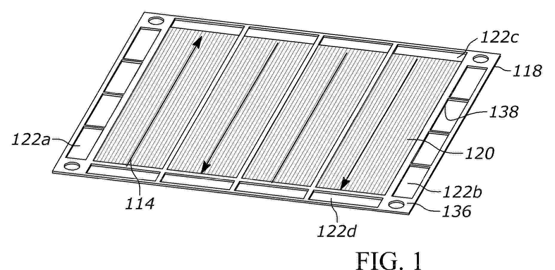
Resumen de: EP4760826A1
Systems and methods for manufacturing a large-sized electrochemical assembly (200) are described herein. In some approaches, the electrochemical assembly (200) comprises a first gas manifold plate (202), a second gas manifold plate (206) and a plurality of electrochemical cell repeating unit (210) disposed between the first gas manifold plate (202) and the second gas manifold plate (206). Each electrochemical cell repeating unit (210) includes a large-size metal sheet substrate (220) with isolated smaller size porous metal structures (224) on the large-size metal sheet substrate (220). An anode layer (116A), an electrolyte layer (116B) and a cathode layer (116C) are fabricated on the large-size metal substrate (220) using thin film deposition technology. The electrochemical assembly (200) comprises a flow field design including a plurality of risers (232) of the electrochemical each large-size metal sheet substrate (220) and interconnect (222) of each electrochemical cell repeating unit to uniformly distribute a first feed stream (236) and a second feed stream (238) to each electrochemical cell repeating unit (210).
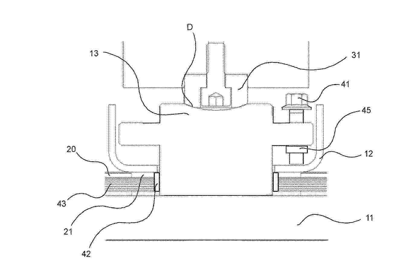
Resumen de: EP4760830A1
The present invention relates to a system (100) for accommodating electrochemical cell stacks (10A, 10B) comprising a housing (20) and a compression system (30). According to the invention, a receptive element (13) separate from the housing (20), is arranged to an end of the at least one electrochemical cell stack (10A, 10B) and extending through a wall of the housing (20) for receiving the compression force exerted by compression system (30) and transmitting it on said end of the at least one electrochemical cell stack (10A, 10B), a gasket structure (42, 43) is arranged between the housing (20) and one of the end elements (11) of the at least one electrochemical cell stack (10A, 10B), wherein the receptive element (13) provides an adjustable clamping structure (12, 14, 15, 41; 17, 18, 19, 44) for providing compressive function for the gasket structure (42, 43) sealing the gas volume inside the housing (20) from the outside of the housing (20).
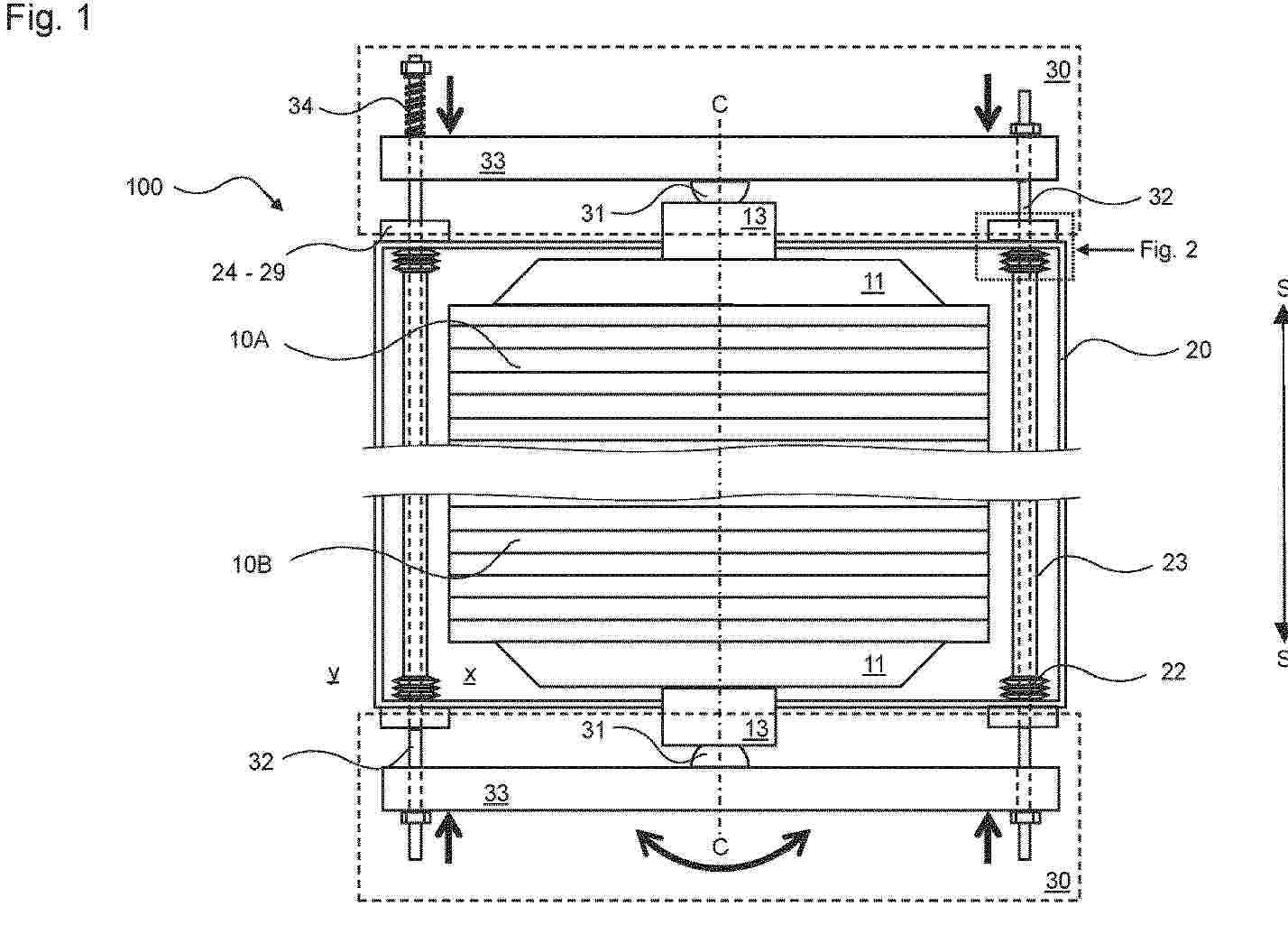
Resumen de: EP4760829A1
The present invention relates to a system (100) for accommodating electrochemical cell stacks (10A, 10B) comprising a housing (20) and a compression system (30) for applying a compression force on the electrochemical cells in the stacking direction (S). According to the invention, the system (100) comprises internal liners (23) extending through the housing (20) in a stacking direction (S) having open ends to the outside of the housing (20), for separating a gas volume (y) inside the liners (23) from an inner space gas volume (x) of the housing (20); wherein each of the tensioning means (32) of the compression system (30) extends through one of the liners (23).
Resumen de: CN121666314A
The invention relates to a device (10, 10 ') for guiding and/or transferring heat between at least two fluid flows (FS1, 2, 3), in particular a process fluid (FS3) and a heat exchange fluid (FS1, 2), having a heat transfer element body (12), the heat transfer element body (12) having a coil structure (14) with a primary coil (16) and a secondary coil (18), the primary coil (16) and the secondary coil (18) are designed to be interleaved in the form of nested coils (14 ') when forming at least one first and one second channel system (20, 22) and when forming a gap system (24), the first and second channel systems (20, 22) each having a first flow width (DW1), the gap system (24) having a second flow width (DW2), the first flow width (DW1) being different from the second flow width (DW2) being different from the second flow width (DW2), and the second flow width (DW2) being different from the second flow width (DW2) being different from the first flow width (DW1). Wherein the first and the second channel system (20, 22) are spatially isolated from a gap system (24), and wherein the gap system (24) has a support structure (26) which passes through the gap system (24).
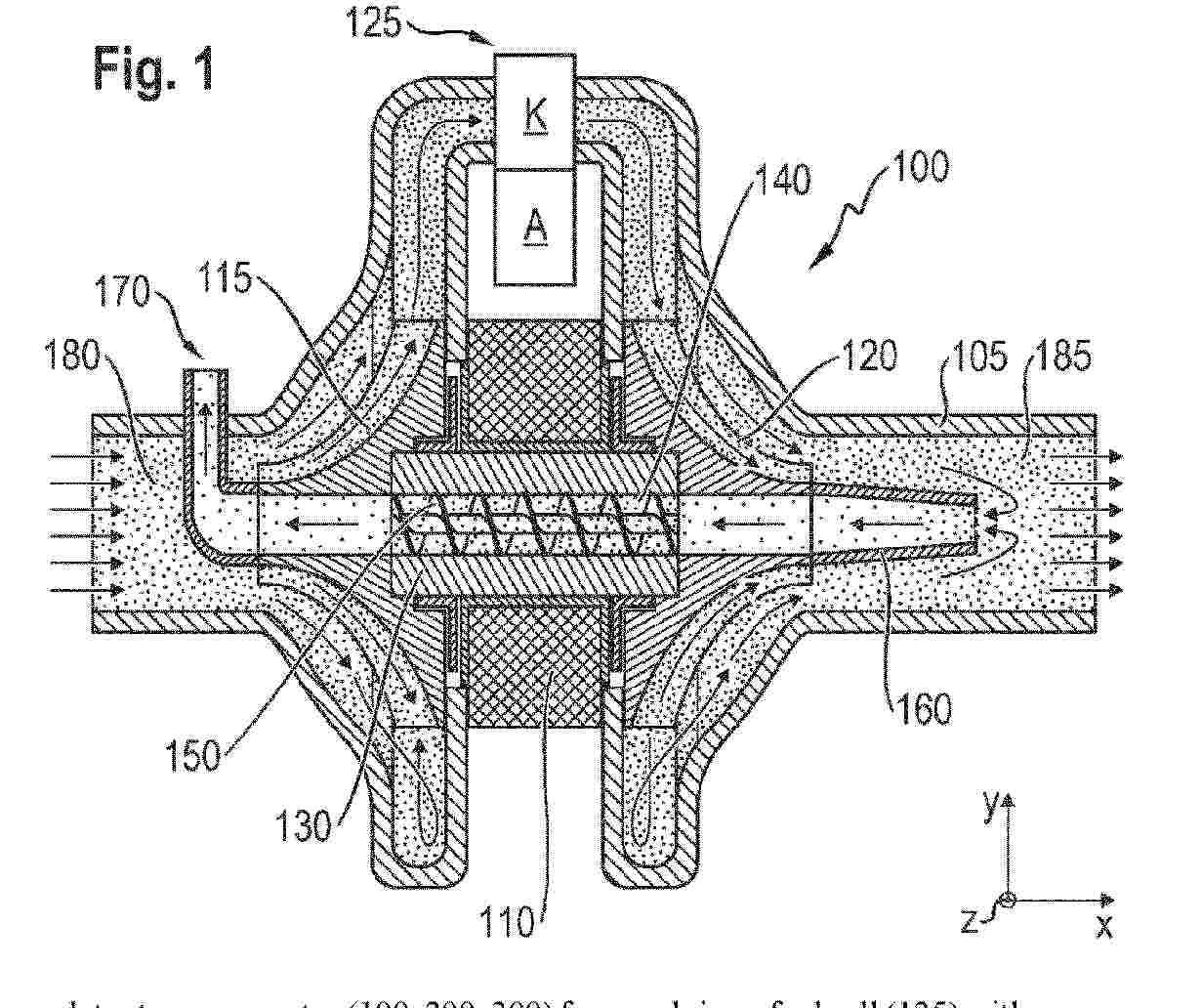
Resumen de: WO2025032105A1
The invention relates to an apparatus (100, 200, 300) for supplying a fuel cell (125) with a gas, comprising: a compression device (115), which is designed to intake and compress the gas and supply it to a cathode (K) of the fuel cell (125); an expansion device (120), which is designed to expand an exhaust gas of the cathode (K); wherein the compression device (115) has an electric motor (110) with a shaft (130) which can rotate about its longitudinal axis, wherein the shaft (130) has, along the longitudinal axis, a cavity (140); a pump device (150, 310), which is designed to pump a portion of the expanded exhaust gas (185) through the cavity (140) of the shaft (130) toward the compression device (115).
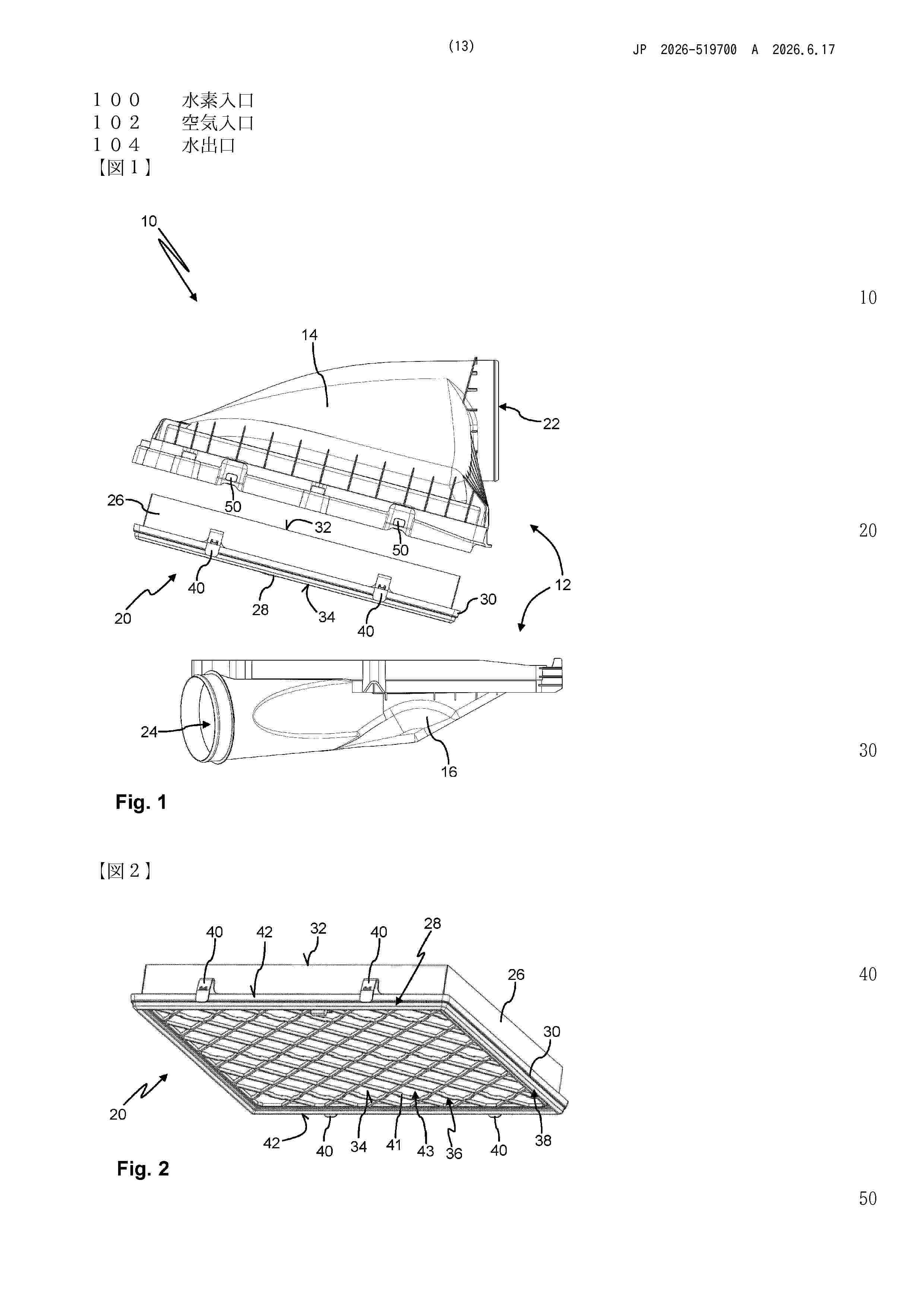
Resumen de: WO2024251472A1
The invention relates to a filter insert with at least one filter medium body. Downstream, the filter insert is supported by a grid section of a support element. The grid section has planar flow openings and is preferably formed with ribs which cross one another. The support element has at least one latching means which is designed integrally with the grid section and by means of which the filter insert can be latched to a housing cover of a filter device. A sealing element is held on the support element and, in the latched state, seals the filter insert with respect to the housing cover. When a filter housing is opened, the filter insert remains held by virtue of the latching to the housing cover. Dirt which has accumulated on the unfiltered raw side (between the filter insert and the housing cover) thus does not enter a housing lower part which has a clean-side outlet.
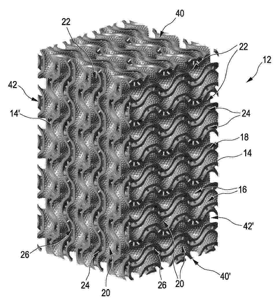
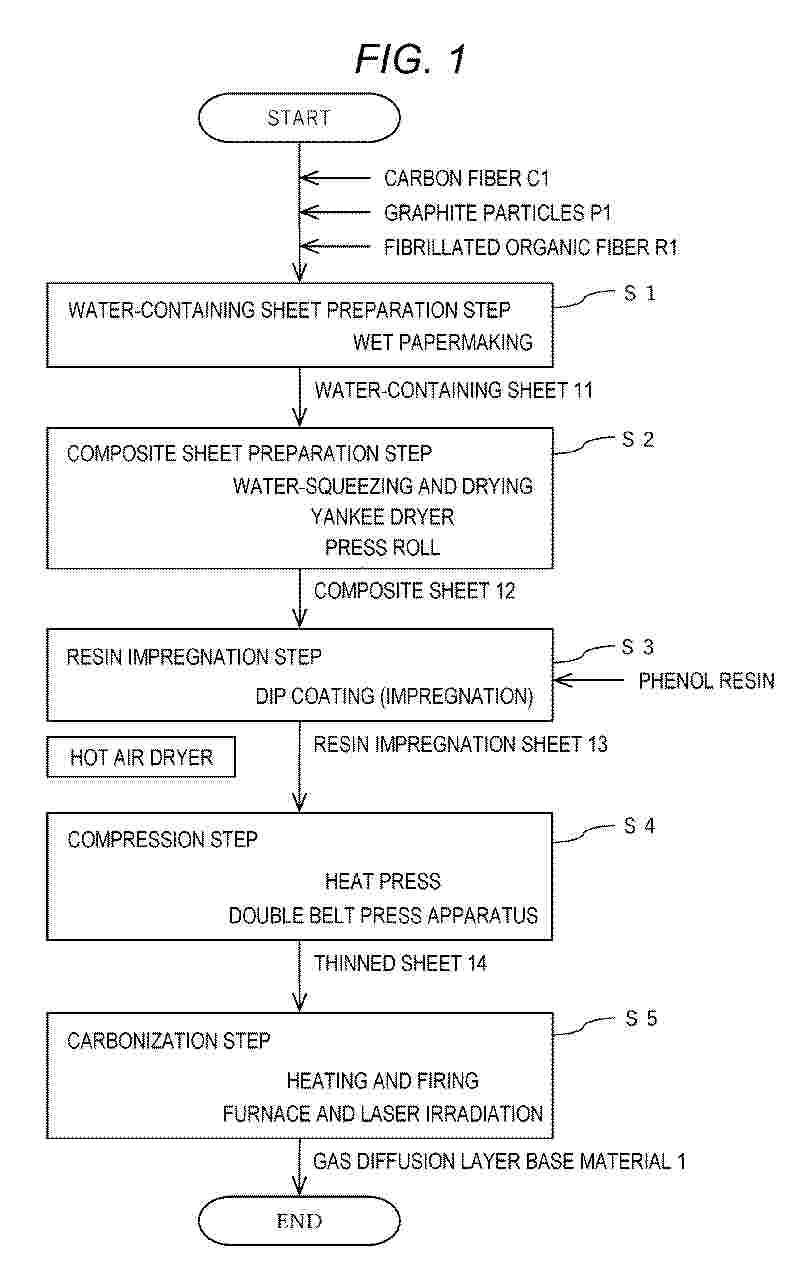
Resumen de: EP4759786A1
A method for producing a fuel cell gas diffusion layer base material sequentially Includes: a water-containing sheet preparation step (S1) of preparing a water-containing sheet (11) containing a carbon fiber (C1), graphite particles (P1) having a particle diameter more than 120 µm as measured by a laser diffraction/scattering method, and a fibrillated organic fiber (R1), which is to be carbonized in a subsequent carbonization step (S5), by using a slurry containing the carbon fiber, the graphite particles, and the fibrillated organic fiber; a composite sheet preparation step (S2) of preparing a composite sheet (12) by water-squeezing and drying the water-containing sheet; a resin impregnation step (S3) of preparing a resin impregnation sheet (13) by impregnating the composite sheet with a carbon precursor resin to be carbonized in the subsequent carbonization step; a compression step (S4) of preparing a thinned sheet (14) by compressing the resin impregnation sheet; and the carbonization step of heating and firing the thinned sheet in a non-oxidizing atmosphere.
Resumen de: WO2025031908A1
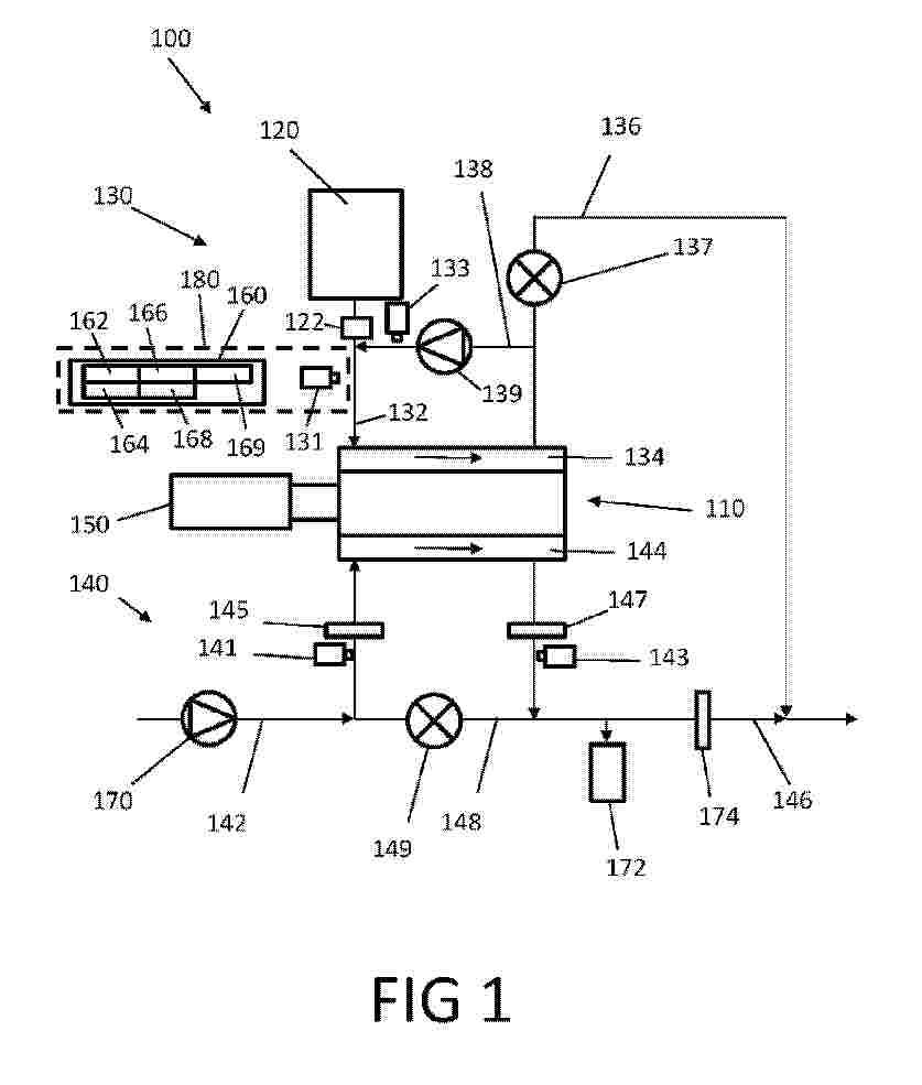
The present invention relates to a method, a control device (160) and a computer program for determining a moisture content in a gas mixture present in an anode conducting system (130) of a fuel cell system (100), and to a gas mixture analysis device (180) and a fuel cell system (100). The anode conducting system (130) fluidically connects a hydrogen injector (122) to an anode of the fuel cell system (100) and has at least one thermal conductivity sensor (131, 133), which is designed to generate a gas signal which is representative of the thermal conductivity in the gas mixture. The method according to the invention comprises receiving a first gas signal from the at least one thermal conductivity sensor (131, 133) at a first time (t1), transmitting a hydrogen supply signal, which indicates a predefined hydrogen supply rate, to the hydrogen injector (122) at a second time (t2), receiving a second gas signal from the at least one thermal conductivity sensor (131, 133) at a fourth time (t4), at which hydrogen is supplied to the anode conducting system (130), and determining the moisture content in the anode conducting system (130) at least partially based on the first gas signal, the second gas signal and the predefined hydrogen supply rate.
Resumen de: GB2702505A
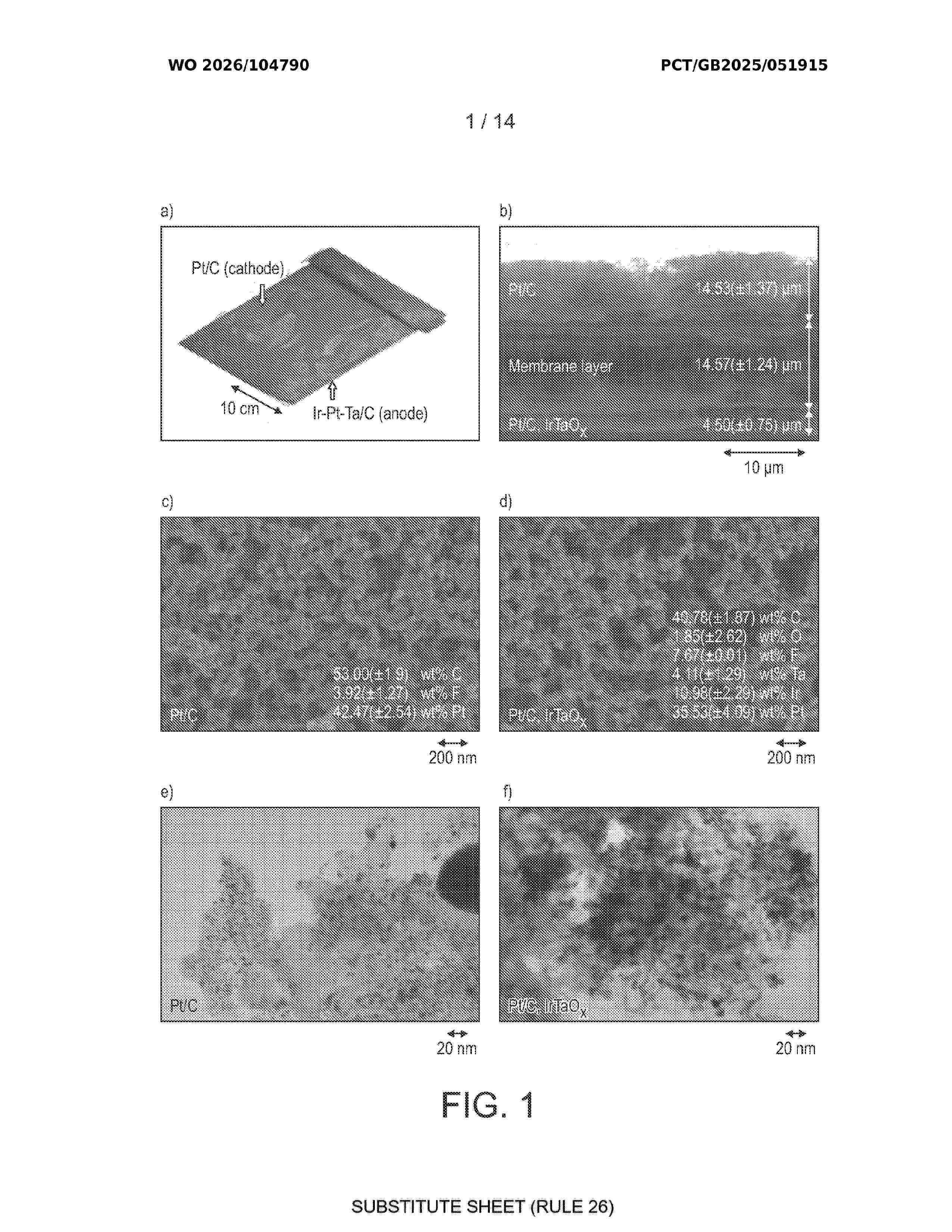
A process for preparing a catalyst, as well as a catalyst, the catalyst comprising an oxygen evolution reaction electrocatalyst OER, a hydrogen oxidation reaction HOR electrocatalyst, and a particulate solid support are described. The OER electrocatalyst and the HOR catalyst are both supported on the particulate solid support. The OER is deposited from an aqueous mixture comprising a particulate solid support and a halide free metalate which comprises iridium and/or ruthenium. The pH of the mixture is reduced to ≤7 to precipitate the oxygenated metal into the solid particulate support. In the process, the OER electrocatalyst is deposited before the HOR electrocatalyst. The catalyst may be incorporated into a catalyst coated membrane (CCM) and used in a fuel cell. Figure 1a
Nº publicación: GB2702524A 17/06/2026
Solicitante:
JOHNSON MATTHEY PUBLIC LIMITED CO [GB]
UNIV OF LEICESTER [GB]
Johnson Matthey Public Limited Company
University of Leicester
Resumen de: GB2702524A
A method for recycling a catalyst coated membrane comprising an ionomer membrane coated on either side by catalyst layers. The method comprises soaking the catalyst coated membrane in a first solvent such as ethanol, transferring the catalyst coated membrane from the first solvent into a second solvent, such as a mixture of water and propanol, which is different to the first solvent and subjecting the catalyst coated membrane in the second solvent to an ultrasonic treatment to delaminate the catalyst layers from the ionomer membrane. The method provides a process which can completely delaminate the catalyst layers while safely avoiding any hazardous gas released and results in delaminated components in a desired (e.g. aqueous) solvent after delamination ready for further processing. Figure 7
 BOPI
BOPI
 Sede Electrónica