Si deseas distinguir tus productos, servicios o ambos de los de otra empresa, es posible que necesites una marca o nombre comercial. Descubre qué son, en qué consiste su procedimiento de registro y qué implica.

Información sobre los plazos de presentación de solicitudes de transformación de marcas de la Unión Europea en marca nacional española. Más información


Si tienes un nuevo dispositivo, producto o procedimiento que resuelva un problema técnico o tenga una ventaja práctica, existen distintas formas de protegerlo en España y en otros países. Descubre cómo hacerlo.

¿Tu innovación reside en la estética, la ornamentación o la apariencia de tu producto? Protégela mediante un diseño industrial. Descubre qué derechos confiere el registro y cómo realizar la tramitación.

Las indicaciones geográficas protegen el nombre de un producto originario de una zona geográfica, a la cual le debe una determinada calidad, reputación u otra característica. Descubre qué son, en qué consiste su procedimiento de registro y qué beneficios conceden.

Las patentes publicadas en todo el mundo son una valiosa fuente de información científica, técnica y comercial.

Si eres emprendedor/a o una empresa y quieres potenciar y mejorar la rentabilidad de tu negocio protegiendo de forma adecuada los activos intangibles de tu organización, en este espacio encontrarás lo necesario.


 467
resultados
467
resultados
 Última actualización
27/07/2026 [08:49:00]
Última actualización
27/07/2026 [08:49:00]


 Resultados 100 a 125 de 467

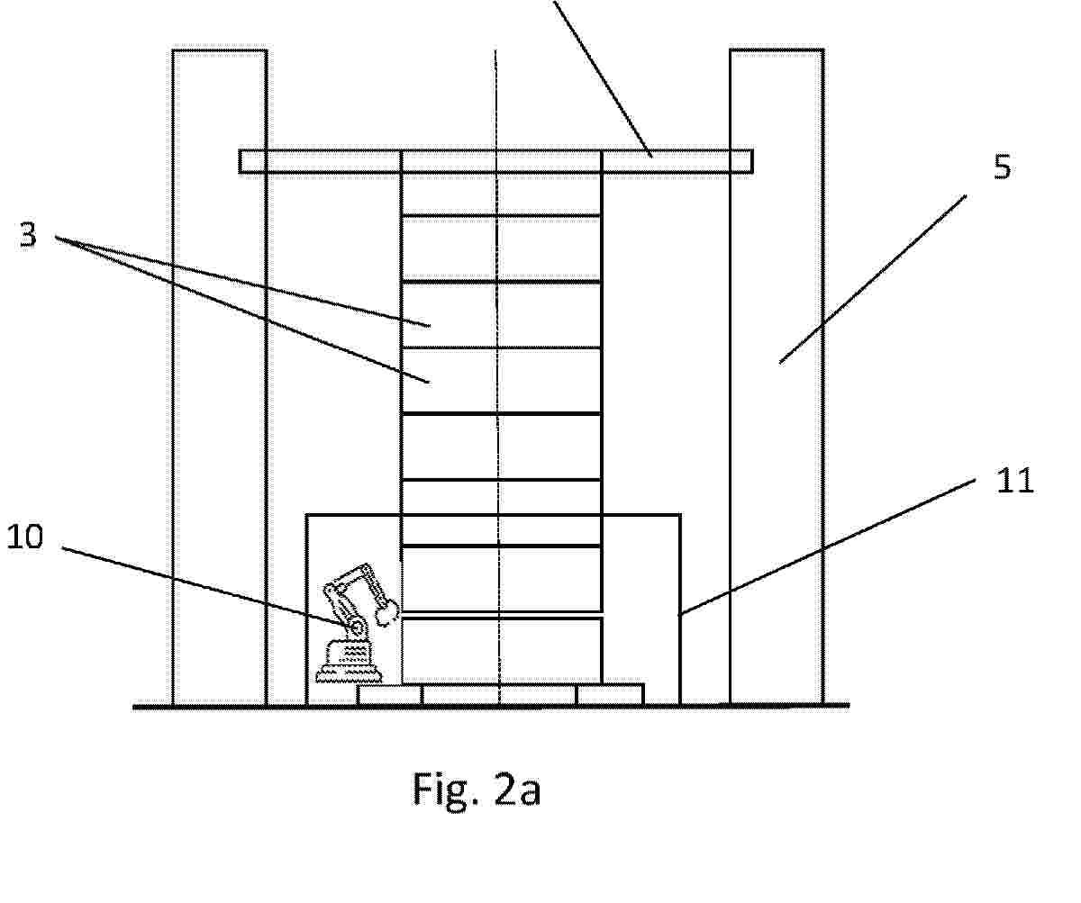
Resumen de: AU2023476825A1
The invention relates to a method for assembling and automatically lifting a wind turbine tower, characterised in that different ferrules (3) composed of wedges (4) are formed in situ using robotised elements (10) that travel along circular guides (9). Welding, inspection and painting elements are simultaneously applied to the inside and outside of the ferrule (3), and work is done at two heights by replicating the circular guides (9) and raising same by means of vertical columns (16). As the ferrules (3) are formed, they are raised by a triangle (6) that travels between columns (5) of the automatic lifting system. Subsequently, by horizontally welding ferrules (3) together, a tower section (2) is formed. The method is applied to tubular towers and frustoconical towers that are 6-8 m in diameter and at least 200 m high.

Resumen de: WO2025016518A1
A method for introducing a component (7) in a nacelle (6) of a wind turbine by means of a guiding tool is disclosed The guiding tool comprises a first part (1) mounted at or near an upper opening (5) of the nacelle (6) and a second part (9) mounted on or forming part of the component (7) being introduced. The first part (1) comprises at least one guiding portion (3) having a wide entrance (3a), a narrow track (3b) and a tapered portion (3c) interconnecting the wide entrance (3a) and the narrow track (3b), and the second part (9) comprises at least one protruding portion (10). The component (7) is lifted to a position above the nacelle (6), and subsequently lowered while causing the at least one protruding portion (10) of the second part (9) of the guiding tool to engage with the wide entrance (3a) of the at least one guiding portion (3) of the first part (1) of the guiding tool and guiding the at least one protruding portion (10) of the second part (9) of the guiding tool along the tapered portion (3c) and the narrow track (3b), so as to position the component (7) relative to the nacelle (6), during the lowering of the component (7).
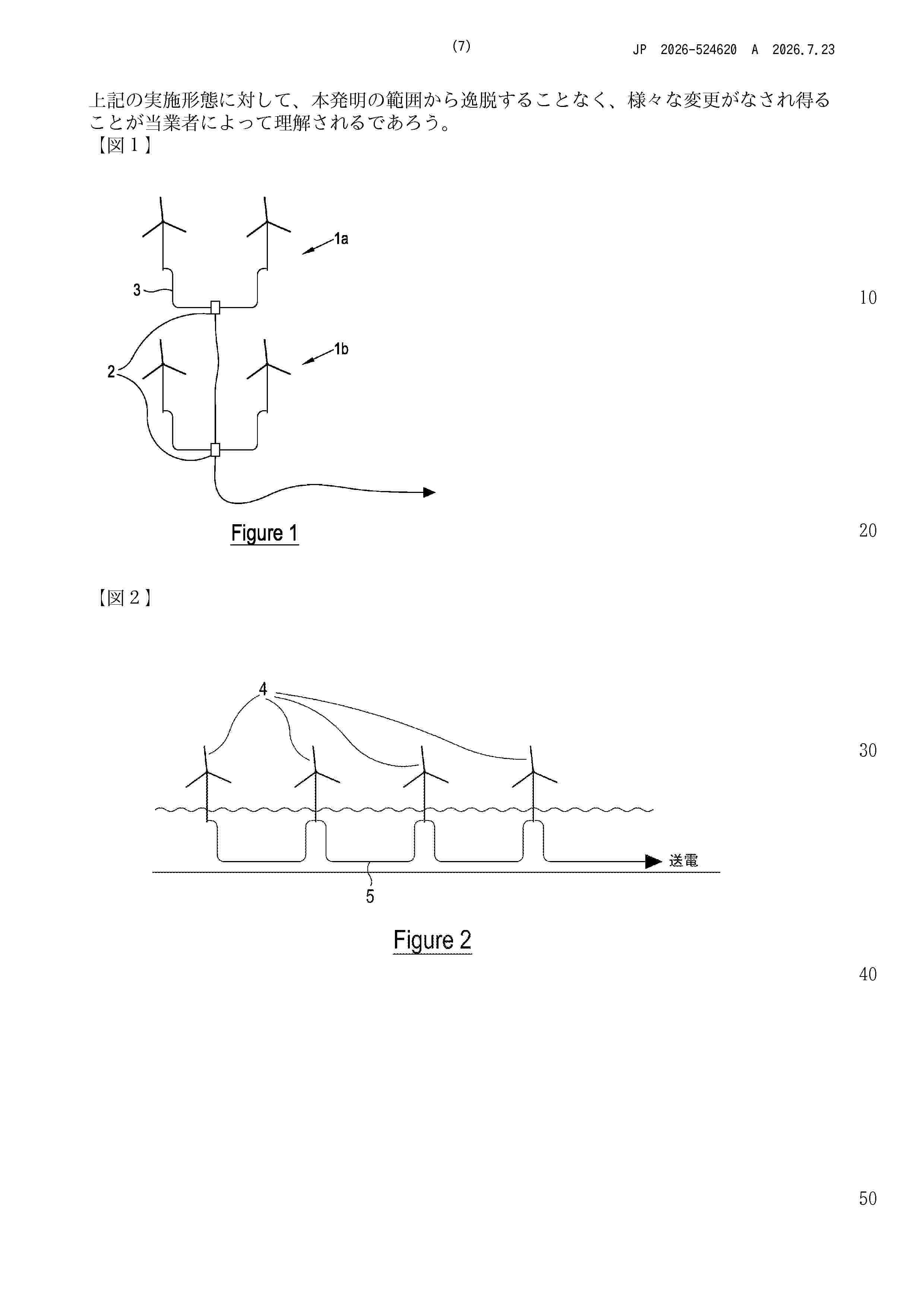
Resumen de: GB2631682A
An electrical protection system of an offshore wind farm comprising one or more arrays of wind turbine generators 13, wherein, for the or each array, a first wind turbine generator provides a connection point 14 connected (a) via a tower cable to a generator of the wind turbine generator, (b) via a collector cable to a subsea substation, and (c) via an inter-array cable to one or more further wind turbine generators of the array. This allows power generated by the array to be routed through the connection point of the first wind turbine generator. The system comprises a circuit breaker located on the first wind turbine generator and above the water, and between the connection point and the collector cable.
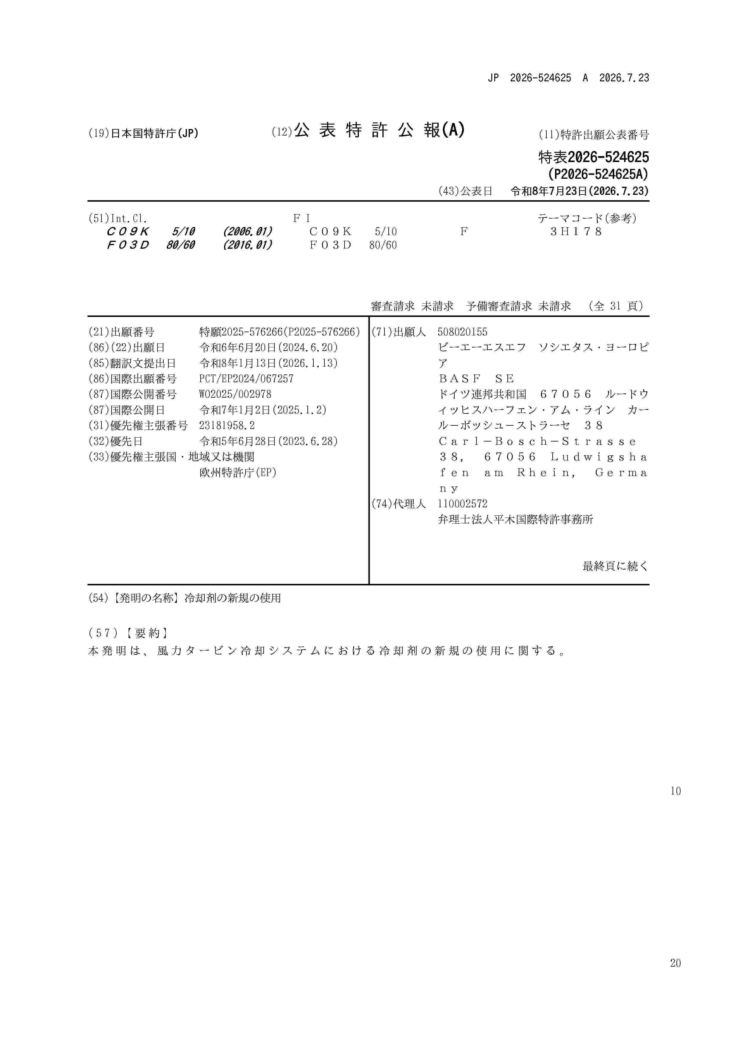
Resumen de: WO2025002978A1
The present invention relates to new uses for coolants in wind turbine cooling systems.
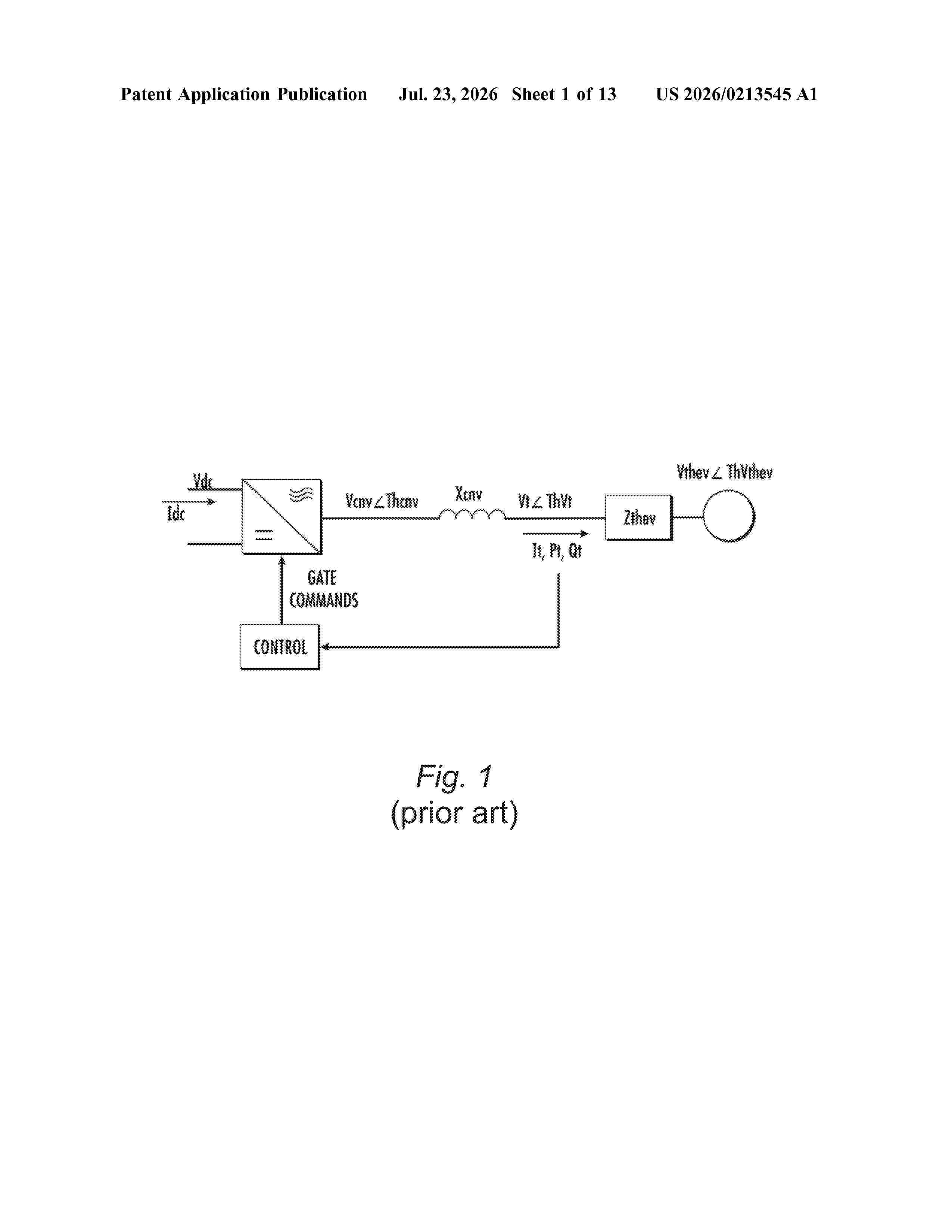
Resumen de: US20260213545A1
A system and method operate a renewable energy source having an inverter-based resource (IBR) system and controlled by a power converter controller. The IBR system is operated in grid-forming mode (GFM) control. The power converter controller receives a control signal that is derived based on a frequency droop function performed on a detected grid frequency at an upstream controller. The power converter controller generates an output power actuator signal based on a frequency droop function performed on the detected grid frequency at the power converter controller. A first compensation is applied to the upstream controller that reduces or eliminates changes in the control signal received by the power converter controller due to changes in the grid frequency.
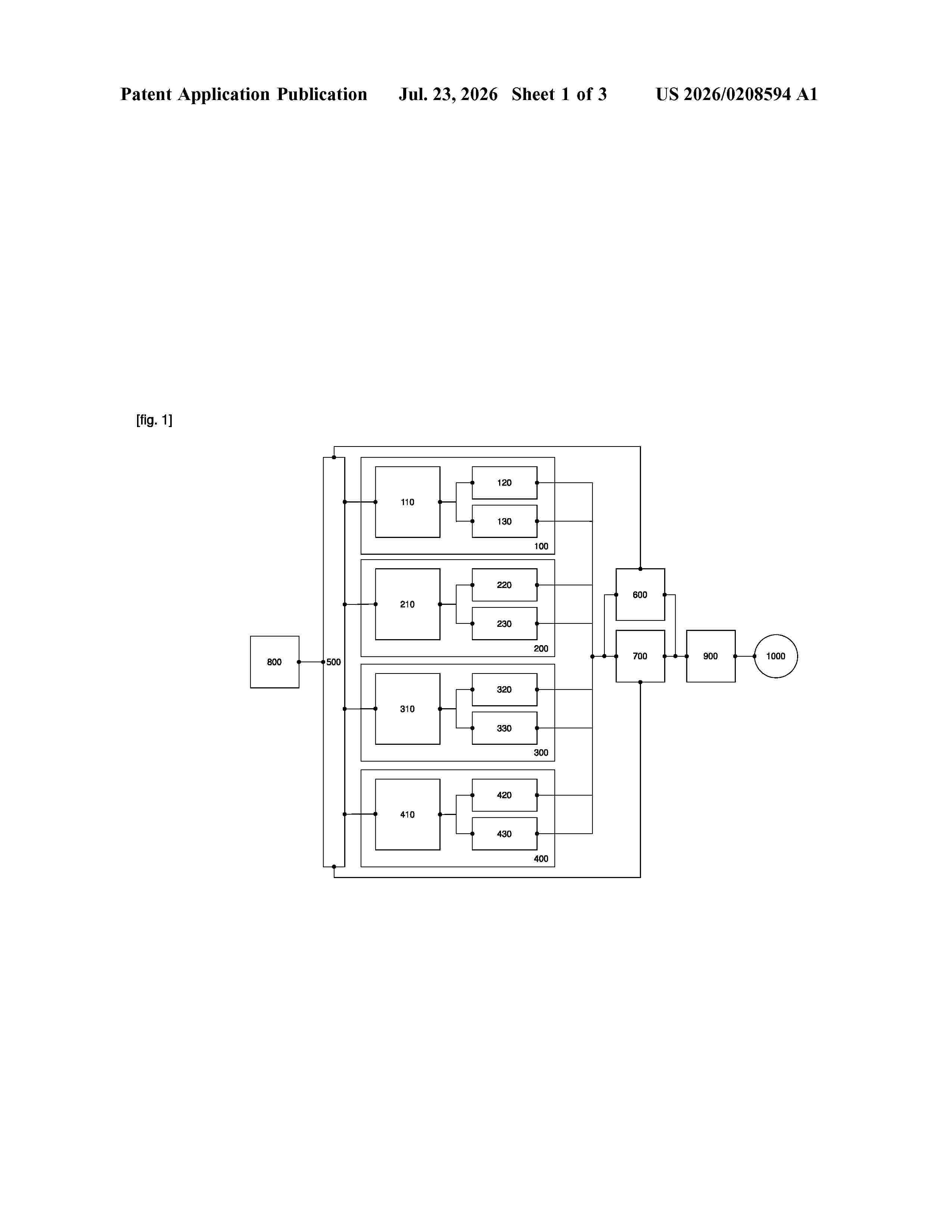
Resumen de: US20260208594A1
0000 The invention relates to power sources for electric vehicles and may be used in the transport industry. The purpose of the present invention is to reduce the risk of damage to the electronic components of an electric vehicle during the operation of the modular battery (100,200,300,400). The purpose is achieved by the modular battery (100,200,300,400) of the electric vehicle due to the fact that the control unit (110,210,310,410) enables the execution of the traction motor inverter capacitor precharge logic.
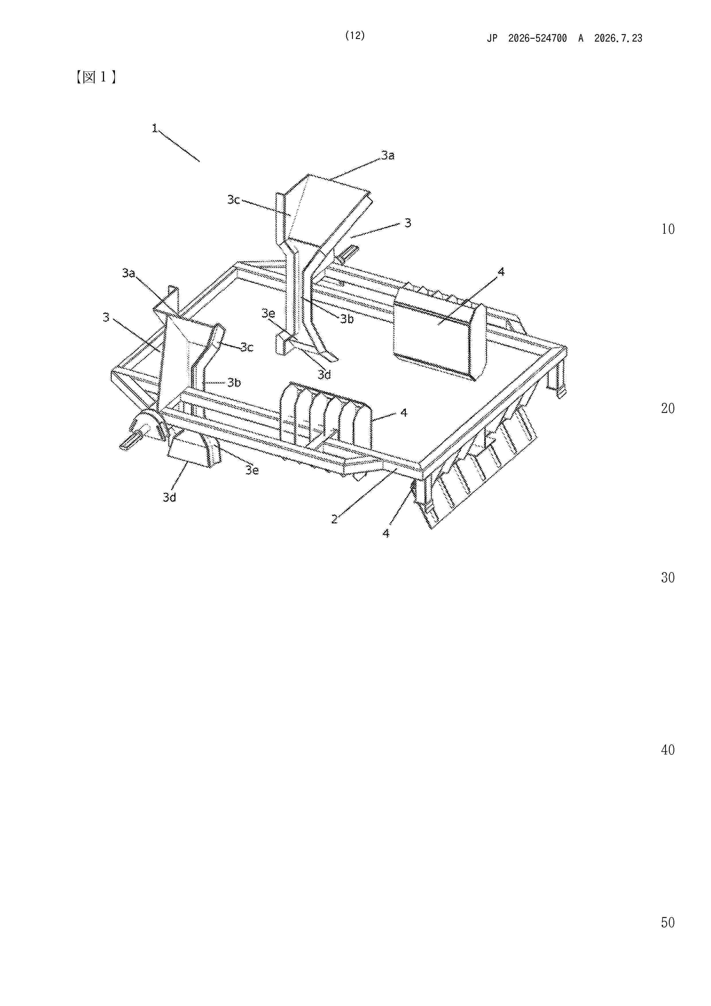
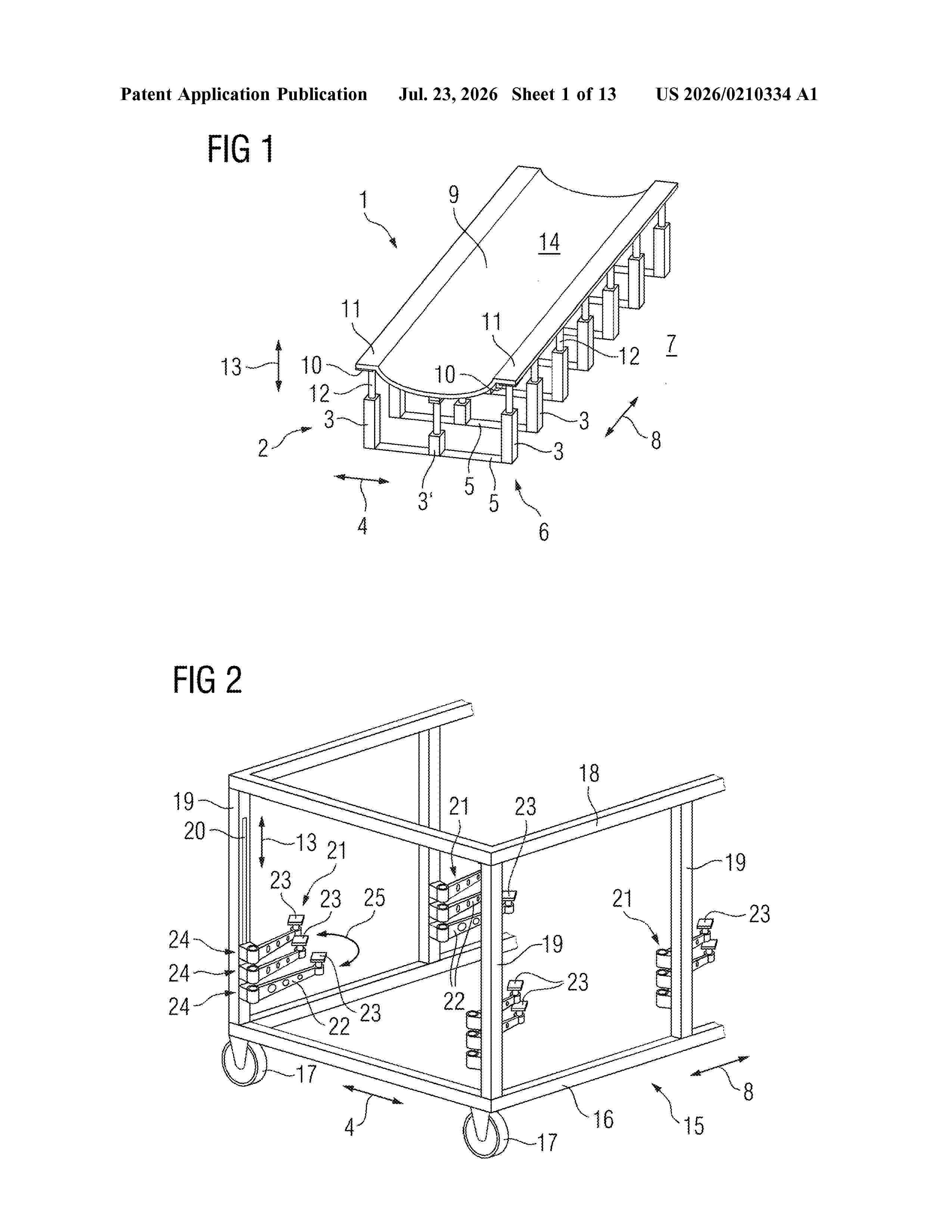
Resumen de: US20260210334A1
Rack as a transport and/or storage device for preform element and/or precast element manufacturing for a wind turbine blade includes a longitudinal frame structure, to which lateral support elements are mounted, which each includes a support portion and which form multiple support assemblies for multiple longitudinal items to store and transport horizontally in the frame structure. The items have a horizontal manufacturing process orientation for use in the manufacturing process. The support assemblies includes width adjustment means for adjusting the distance of support portions of the support assemblies in a width direction to different widths of the items, and/or shape adjustment means for adjusting to different height profiles of supported items in the width direction.
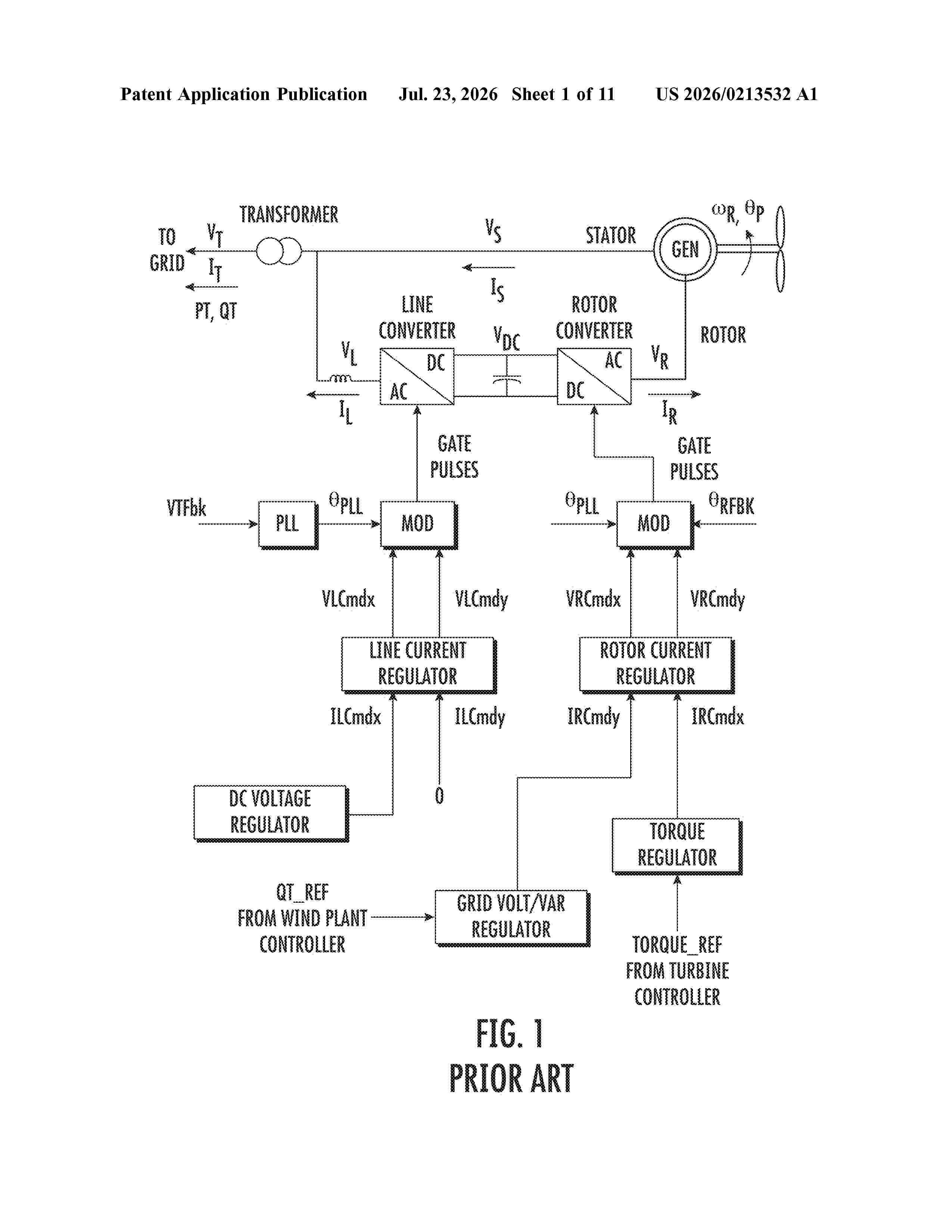
Resumen de: US20260213532A1
0000 A method for constraining grid frequency support of a wind turbine connected to an electrical grid to prevent a trip event in the wind turbine includes receiving, via a controller, one or more speed feedback signals from the wind turbine. Further, the method also includes adjusting, via the controller, one or more parameters of a power regulator of the wind turbine based on the one or more speed feedback signals such that a power output of the wind turbine is less sensitive to changes in at least one of grid frequency or phase angle.
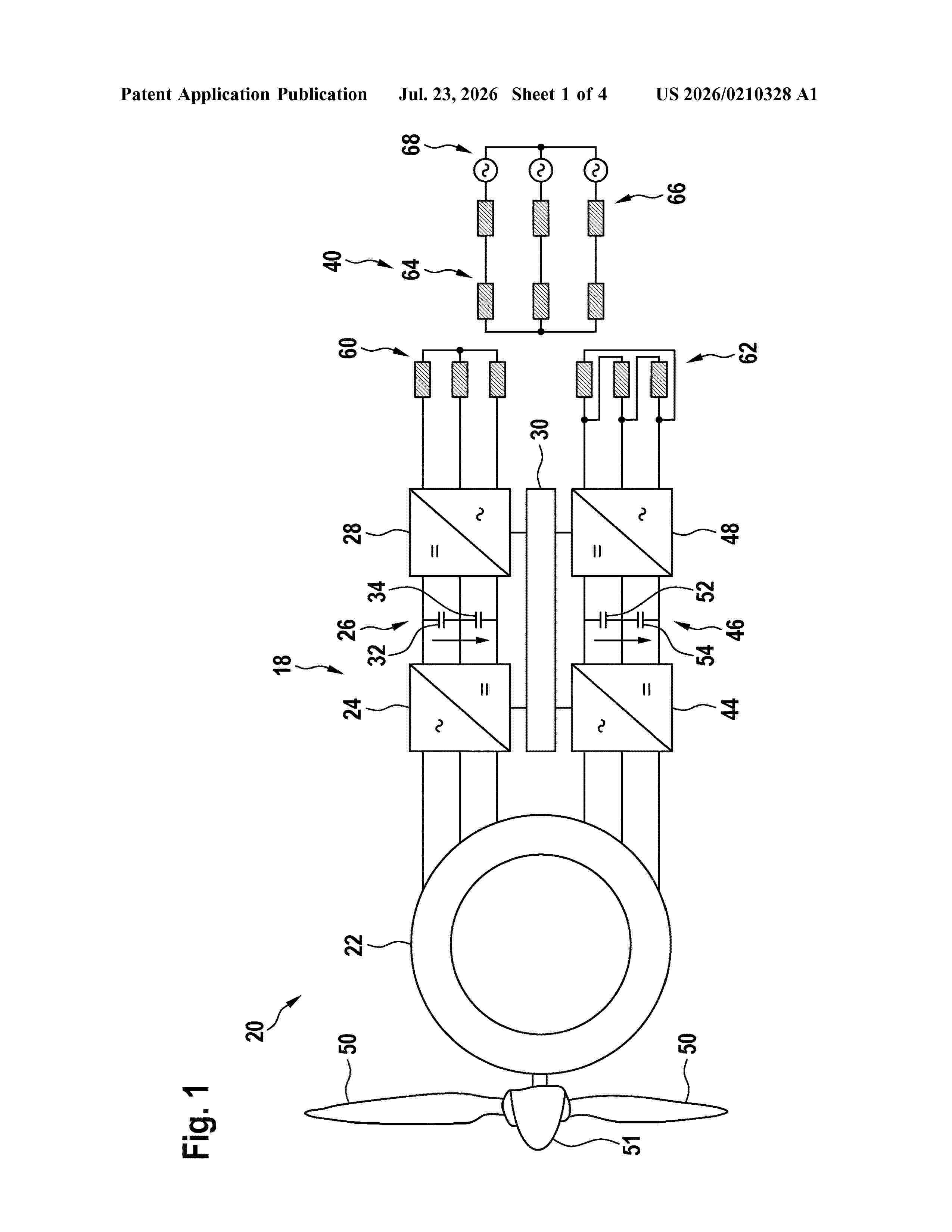
Resumen de: US20260210328A1
0000 A method for avoiding an unintended fall of a blade of a wind turbine when the blade or another blade of the wind turbine is arranged at a rotor hub of the wind turbine is provided. The wind turbine comprises the rotor hub, a rotating electrical machine mechanically coupled to the rotor hub, a machine-side converter electrically coupled to the rotating electrical machine and comprising several semiconductor switches, a DC-link electrically coupled to the machine-side converter, and a grid-side converter electrically coupled to the DC-link and to an electrical grid. The method comprises: generating a short circuit at the DC-link by activating all of the semiconductor switches at the same time.
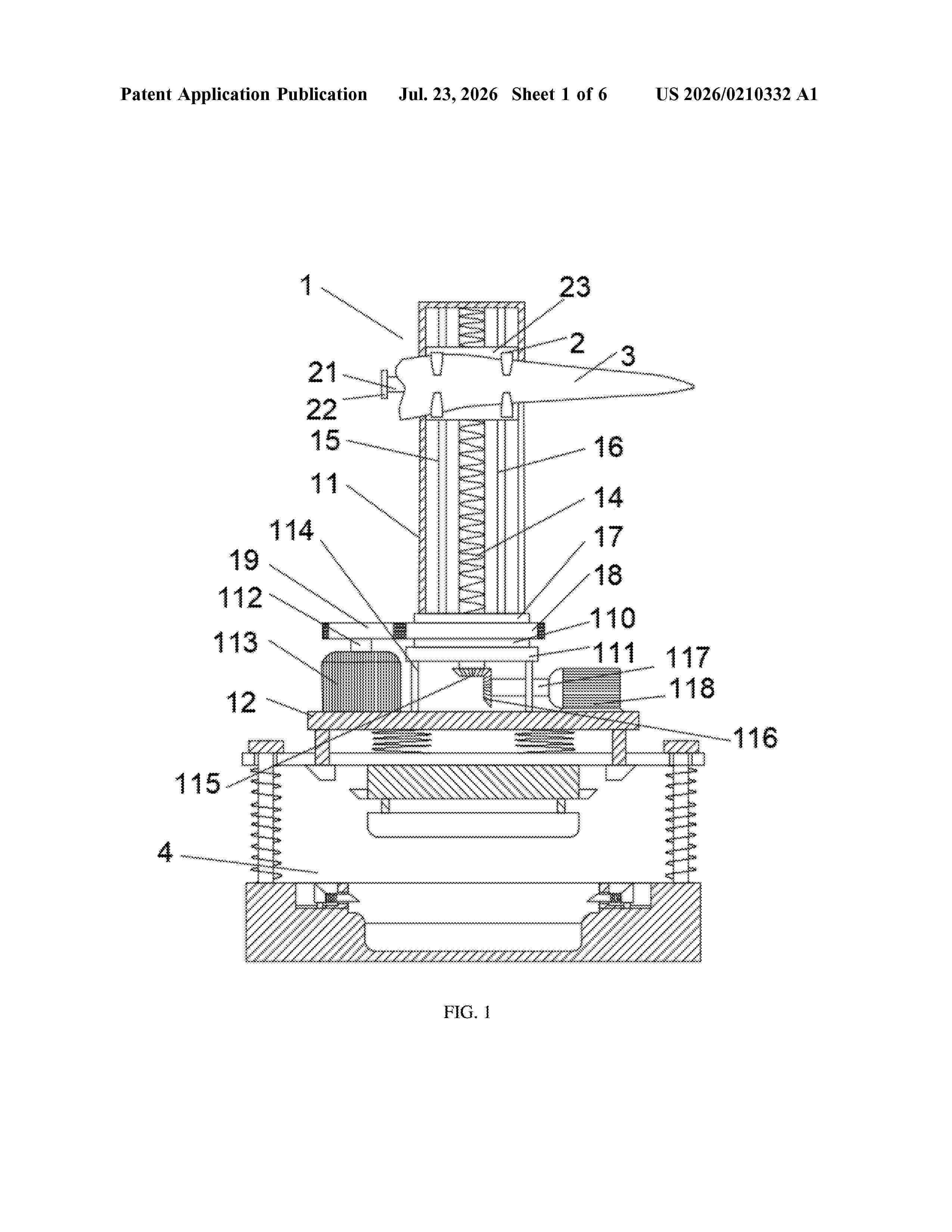
Resumen de: US20260210332A1
0000 The device includes a supporting device body, where the supporting device body includes a shell and a bottom plate, the shell is located above the bottom plate, a lifting block is arranged in the shell, and a lifting device is arranged in the shell, and a lifting end of the lifting device is connected with the lifting block, the shell is fixedly connected to an upper end of a fixed plate, the fixed plate is rotatably connected to an upper end of an support plate, the support plate is fixedly connected to an upper end of a support frame, and a lower end of the support frame is fixedly connected to an upper end of the bottom plate, and the lifting block is connected with a clamping device, and the clamping device clamps a wind turbine blade.
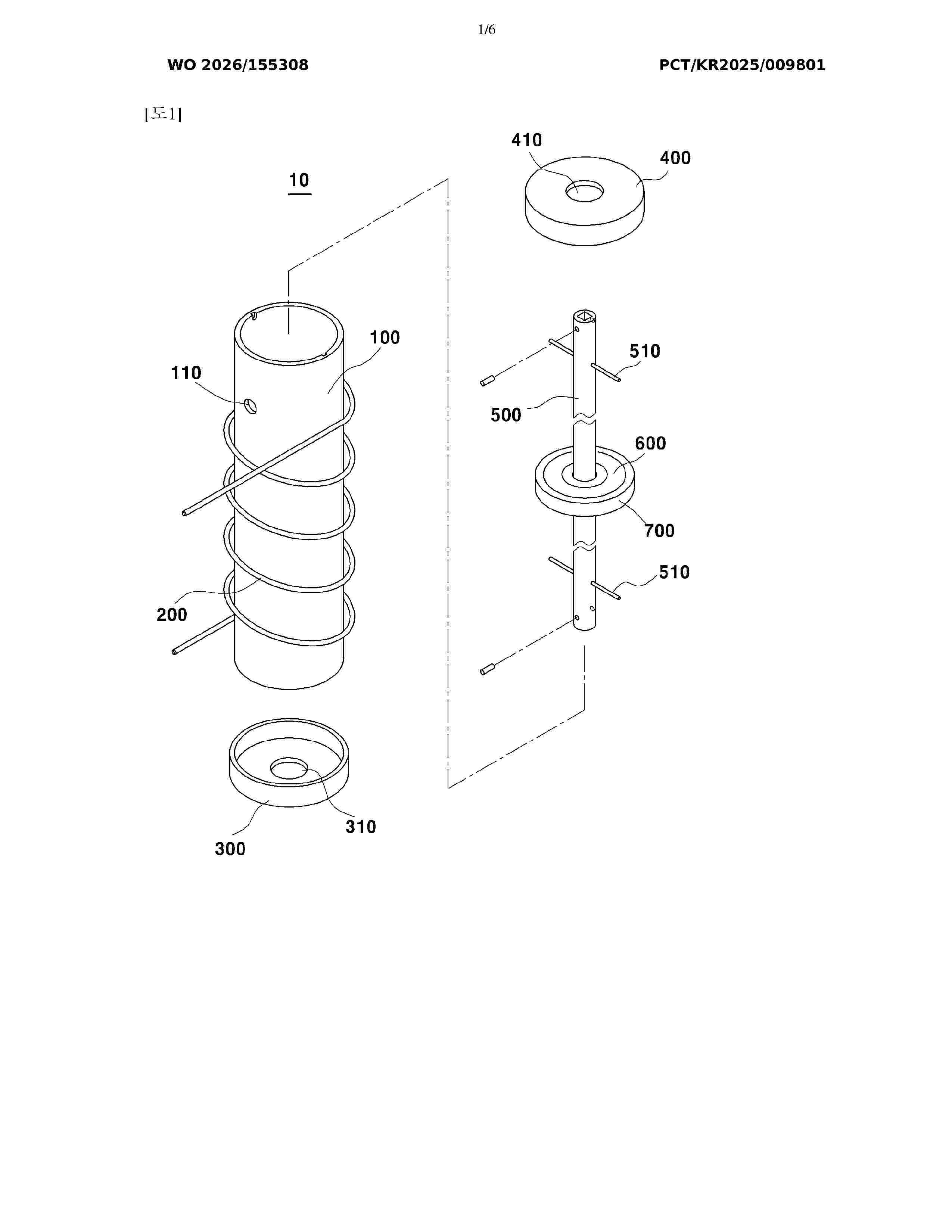
Resumen de: WO2026155308A1
A wind power generation module according to an embodiment of the present invention comprises: a cylindrical housing having a hollow portion; a coil surrounding the housing; a first cap which is coupled to one end of the housing so as to close off the housing, and which has a first ventilation hole; a second cap which is coupled to the other end of the housing so as to close off the housing, and which has a second ventilation hole; a guide rod fixed inside the housing; a magnetic body fitted and coupled to the guide rod so as to be capable of moving back and forth along the guide rod; and a packing coupled to the edge of the magnetic body so as to prevent air leakage between the magnetic body and the inner surface of the housing, wherein, when air is fed through the first ventilation hole, the magnetic body is lifted by means of the pressure of the air, the air above the magnetic body is discharged through the second ventilation hole as the magnetic body is lifted, and the magnetic body is lowered again by gravity and moves back and forth.
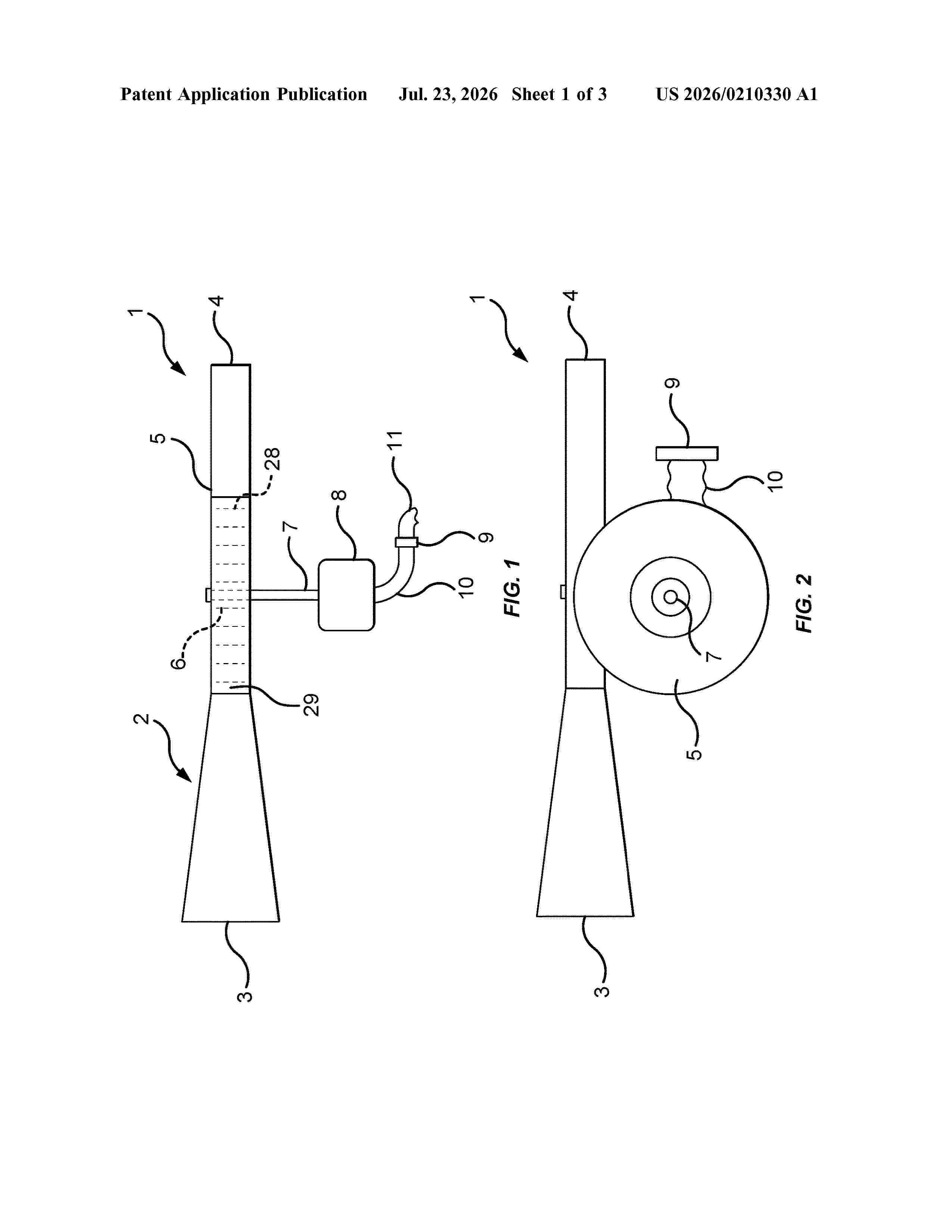
Resumen de: US20260210330A1
Electric generating assemblies wherein such assemblies are intended to be mounted on a vehicle, such that a front of a hollow funnel is directed to the front of the vehicle. As the vehicle moves forward, the funnel picks up wind which is passed through the funnel and turns a fan which contains vanes that have leading edges wherein the leading edges are one inch or greater distance from the inside wall of the funnel, which generates electricity.
Resumen de: DE102025101937A1
Die Erfindung betrifft eine Befestigungsanordnung zum Befestigen eines Antriebsstrangs an einer Windkraftanlage (10). Die Windkraftanlage (10) weist einen Turm (28) und eine daran angeordnete Gondel (20) auf. Die Befestigungsanordnung weist wenigstens eine antriebsstrangseitige Befestigungsschnittstelle (52, 54, 56, 58) und einen gondelseitigen Endabschnitts des Turms (28) auf, wobei der Antriebsstrang an der antriebsstrangseitigen Befestigungsschnittstelle (52, 54, 56, 58) mit der Gondel (20) verbunden ist. Die antriebsstrangseitige Befestigungsschnittstelle (52, 54) ist in einem Bereich über einer gondelseitigen Kante (70) einer umlaufenden Wand des gondelseitigen Endabschnitts des Turms (28) angeordnet. Zudem bezieht sich die Erfindung auf eine Windkraftanlage (10).
Resumen de: WO2026153625A1
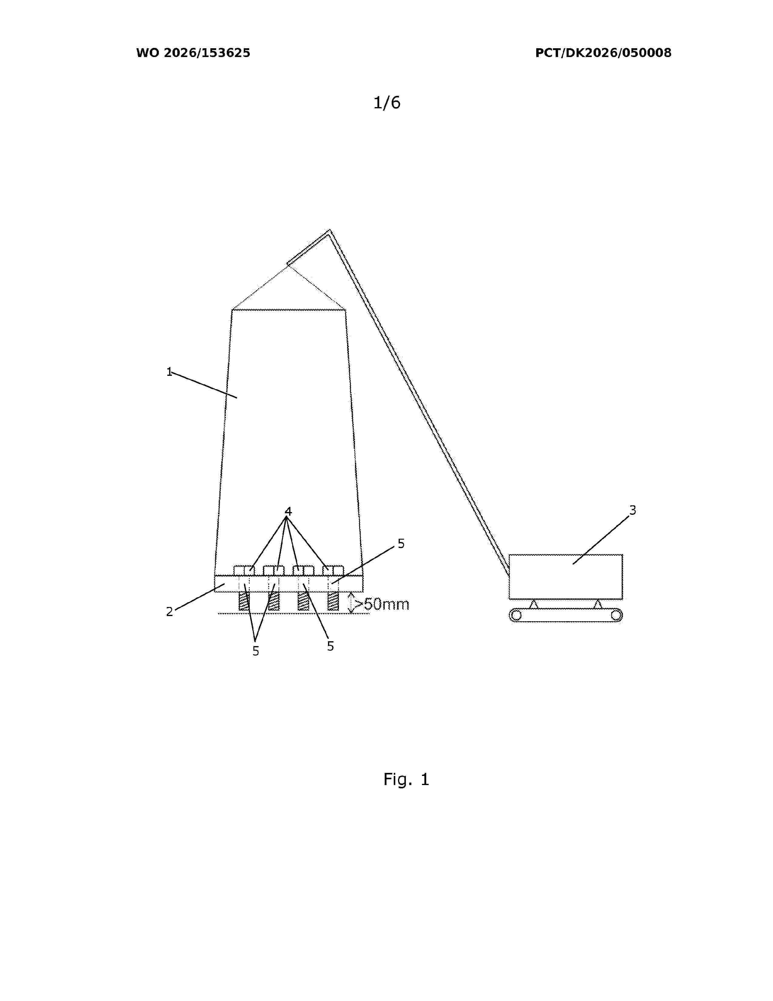
A method for assembling a wind turbine tower is disclosed A first tower section (6) comprises an upper flange (7) provided with a plurality of holes (8), each configured to receive a fastening element (4). At least one cover element (9) is arranged adjacent to the upper flange (7) of the first tower section (6), the at least one cover element (9) covering the plurality of holes (8) of the upper flange (7). A second tower section (1) comprises a lower flange (2) provided with a plurality of holes (5), and fastening elements (4) are arranged in at least some of the holes (5) of the lower flange (2) of the second tower section (1). The second tower section (1) is hoisted to a position above the first tower section (6), and the fastening elements (4) are arranged in abutment with the at least one cover element (9). The second tower section (6) is moved into alignment with the first tower section (1), the at least one cover element (9) is removed, allowing the fastening elements (4) to enter the holes (8) of the upper flange (7), and the second tower section (1) is attached to the first tower section (6) by means of the fastening elements (4, 12).
Resumen de: WO2026153675A1
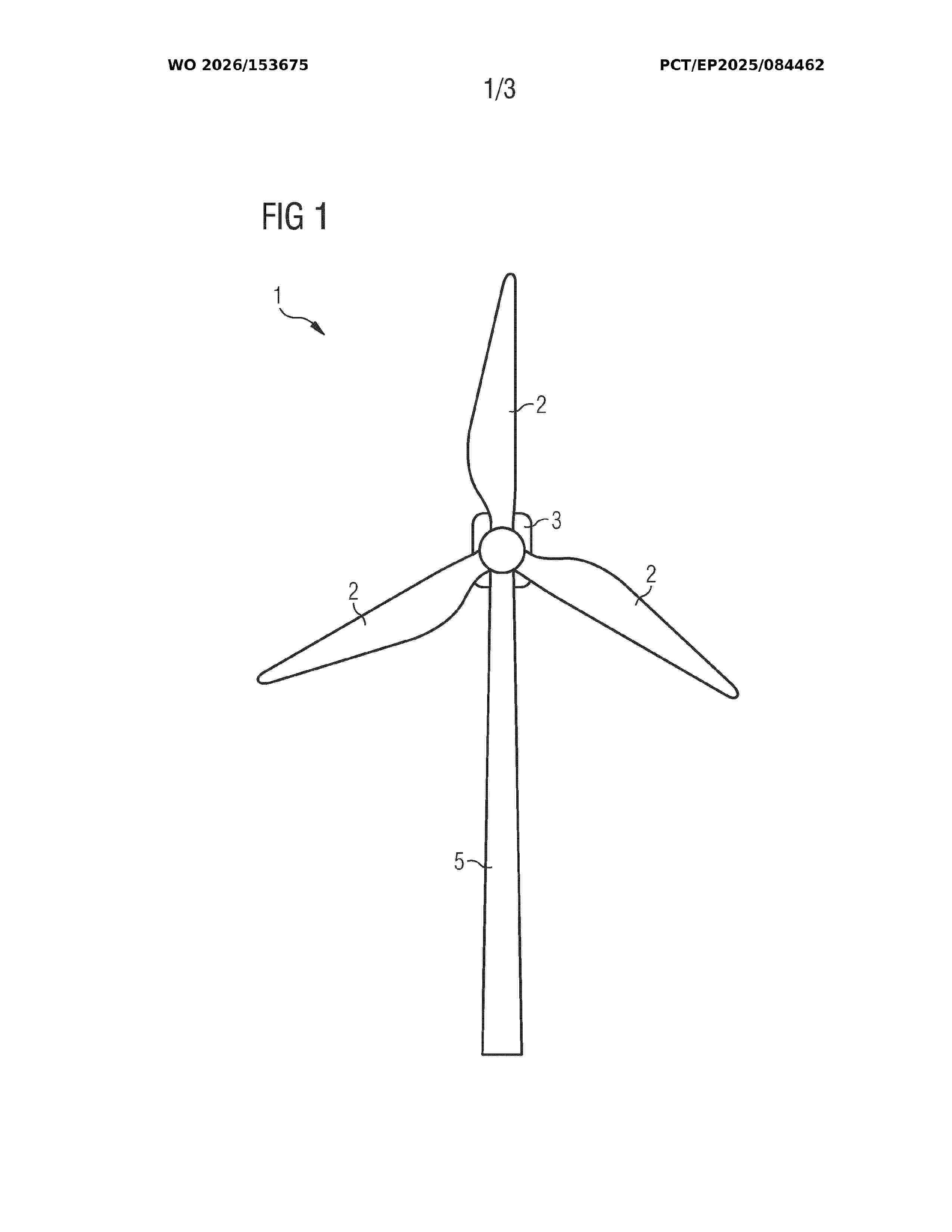
A rotor blade (2) for a wind turbine (1) comprising a vibration damping system (10) is provided. The vibration damping system comprises at least one liquid damping device (11) mounted in the rotor blade, wherein the liquid damping device (11) comprises a vessel (20) that is partially filled with a liquid (21) and with particles (22). The at least one liquid damping device (11) is arranged and tuned to damp vibrations of the rotor blade (2) that occur during a standstill of the rotor blade (2) when the rotor blade (2) is mounted to the wind turbine (1).
Resumen de: US20260213694A1
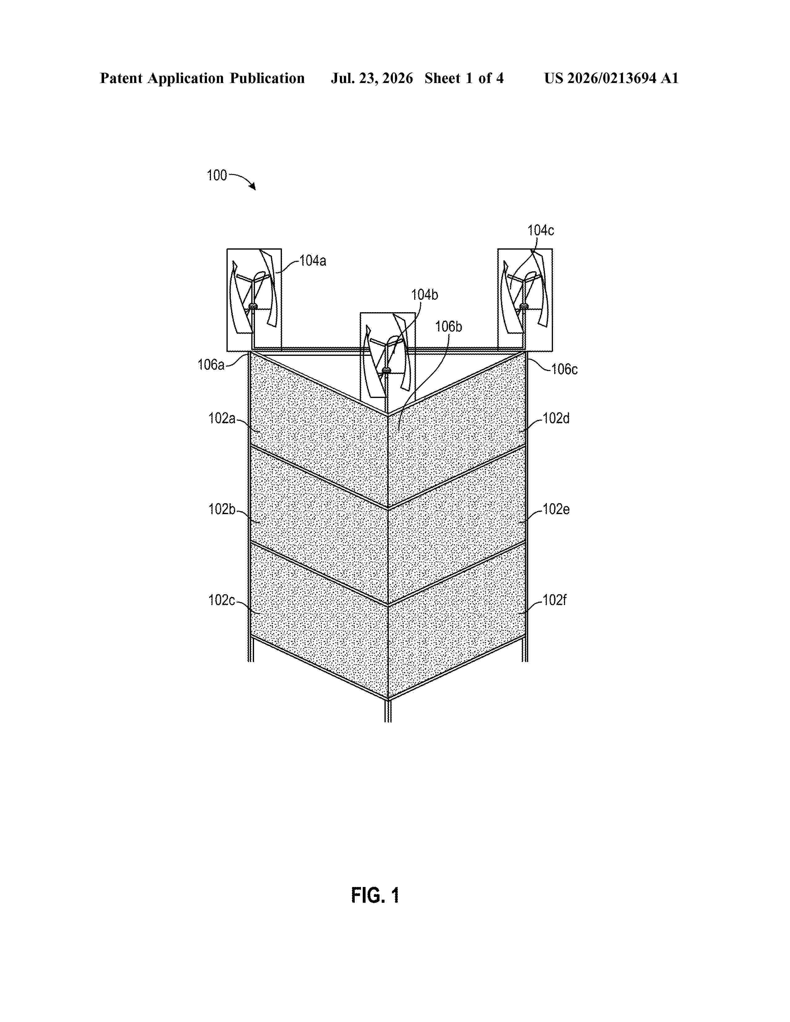
Systems and devices provided herein facilitate offshore energy production. Systems may include a mounting frame including at a first vertical side and a second vertical side, wherein the first and second vertical sides are arranged at an angle relative to one another; a first set of modular photovoltaic (PV) panels affixed to the first vertical side, the first set of modular PV panels configured to capture light incident on the first set of modular PV panels and convert the light incident into energy; a second set of modular PV panels affixed to the second vertical side, the second set of modular PV panels configured to capture light incident on the first set of modular PV panels and convert the light incident into energy; and a set of turbines affixed to each top corner of the mounting structure and configured to capture wind energy and convert the wind energy into energy.
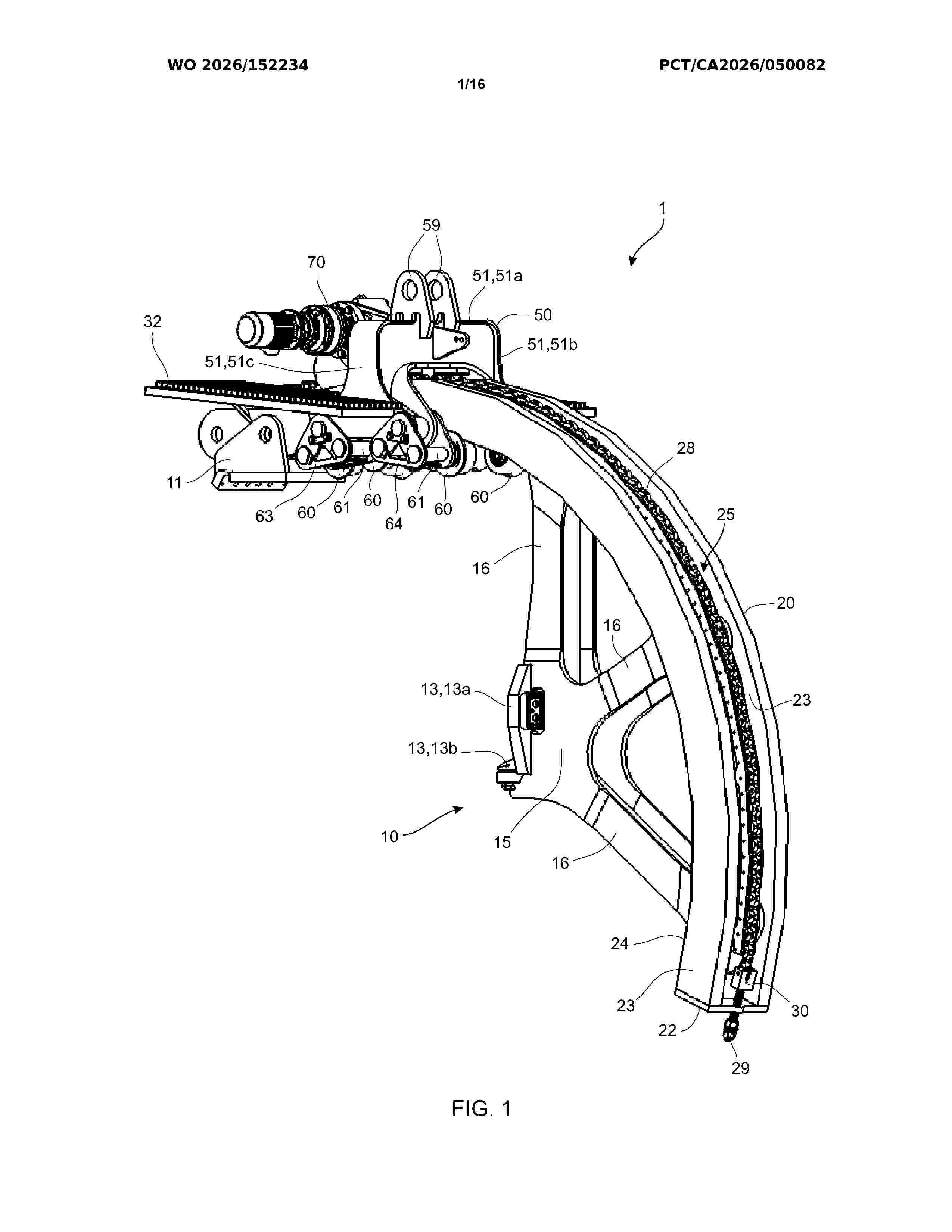
Resumen de: WO2026152234A1
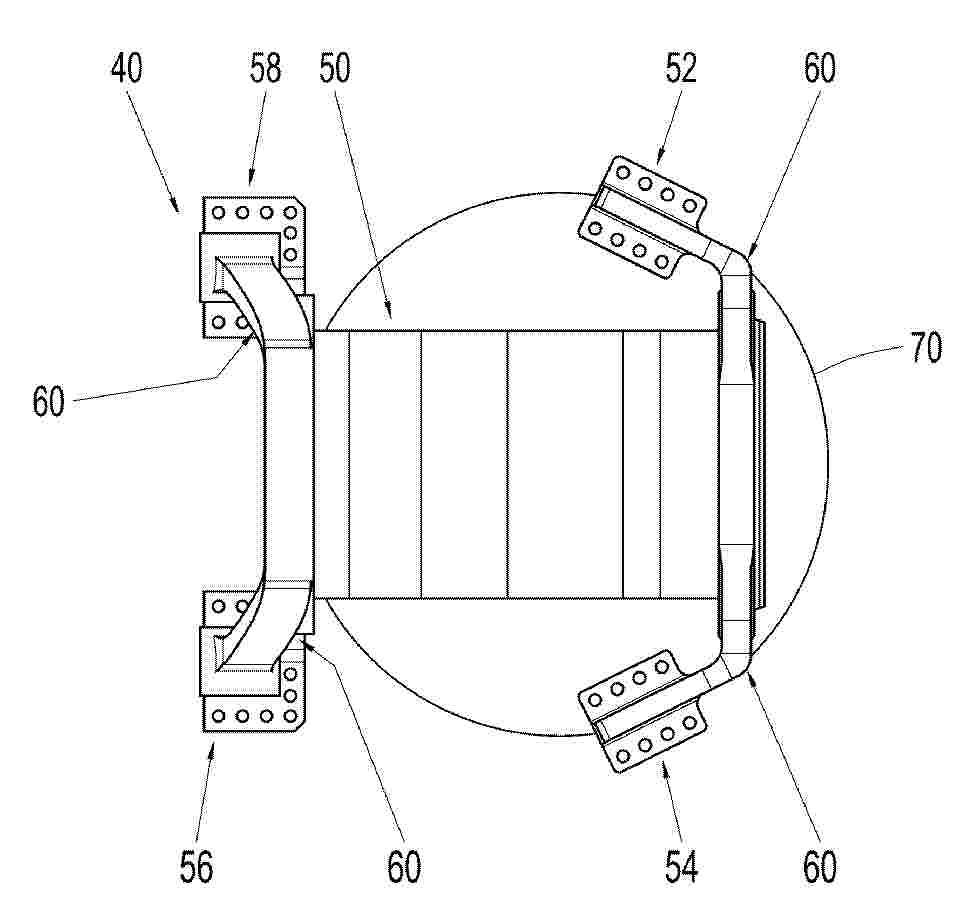
A rotor handling device for handling a rotor of a wind turbine comprises a track assembly comprising an arcuate track. The arcuate track extends between a top of a rotor hub of the rotor and a front of the rotor hub when the rotor is mounted on the wind turbine and the track assembly is mounted on the rotor hub. The rotor handling device further has a carriage on which the arcuate track is movably mounted. The carriage has: at least one lifting lug for connection to a lifting device; at least one wheel on which an underside of the arcuate track rides; and, a motor operatively connected to the arcuate track to drive the arcuate track on the carriage. The device allows turning a rotor so that rotor blades of the rotor are in a substantially horizontal plane without using a ground-based crane.
Resumen de: US20260210001A1
0000 A method of recycling composite material, the composite material comprising reinforcement fibres embedded in a matrix material. The method comprises: loading the composite material into a container; treating the composite material in the container with a liquid; transporting the container to a recycling station, wherein the liquid degrades the matrix material in the container during the transporting of the container; and at the recycling station, recycling the reinforcement fibres by separating them from the matrix material. WO
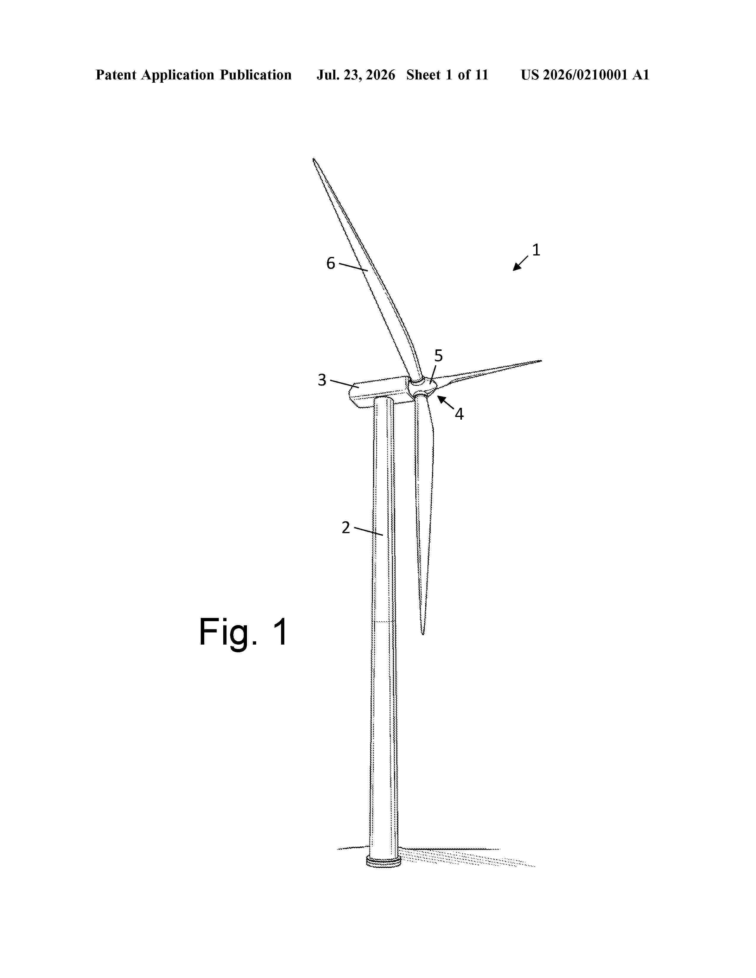
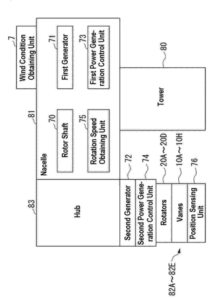
Resumen de: EP4779147A1
0001 The wind power generation device includes a rotor shaft rotatable around a first rotation axis, a first generator for converting rotational energy of the rotor shaft into electric power, a rotator connected to the rotor shaft and rotatable around a second rotation axis which is different from the first rotation axis, a vane fixed to the rotator, and a second generator for converting rotational energy of the rotator into electric power.
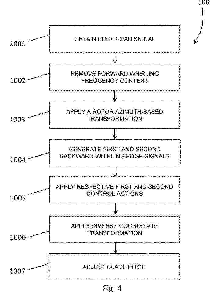
Resumen de: WO2025056131A1
The invention relates to adjusting individual pitch of wind turbine rotor blades. The invention involves obtaining an edge load signal indicative of edge loading on the individual rotor blades in a wind turbine rotor rotational frame, removing forward whirling frequency content corresponding to forward whirling motion from the edge signal, and applying a rotor azimuth-based transformation operation to obtain a backward whirling edge signal in a wind turbine rotor azimuth fixed frame. The backward whirling edge signal is split into first and second signals corresponding to disturbances at an edge frequency and at the edge frequency minus 2P, respectively. First and second control actions for mitigating backward whirling motion are applied to the first and second signals, respectively. The resulting signals are transformed back into rotor rotational frame to obtain individual pitch offset values which are then used to adjust pitch of the rotor blades.
Resumen de: WO2025056132A1
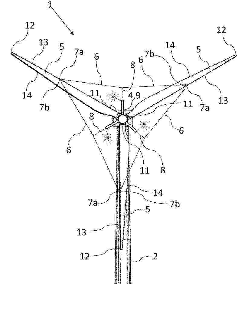
A pitch controlled wind turbine has a tower, a nacelle mounted on the tower, a hub mounted rotatably on the nacelle, and at least three wind turbine blades. Each wind turbine blade extends between a root end connected to the hub via a pitch mechanism, and a tip end. The wind turbine also has at least three blade connecting members, each blade connecting member extending from a connection point on one wind turbine blade towards a connection point on a neighbouring wind turbine blade, where the connection point on a given wind turbine blade is arranged at a distance from the root end and at a distance from the tip end of the wind turbine blade. The wind turbine also has at least three pre-tension members, each pre-tension member being connected to one of the blade connecting members and to the hub via a tensioning device, the tensioning device provides radial movement of a radially inward end of the pre-tension member with respect to an axis of rotation of the hub due to extension or retraction of the tensioning device, each pre-tension member thereby providing pre-tension in the blade connecting member to which it is connected. A lightning protection system protects each of the tensioning devices from lightning current and provides a lightning current path towards ground.
Resumen de: EP4524395A1
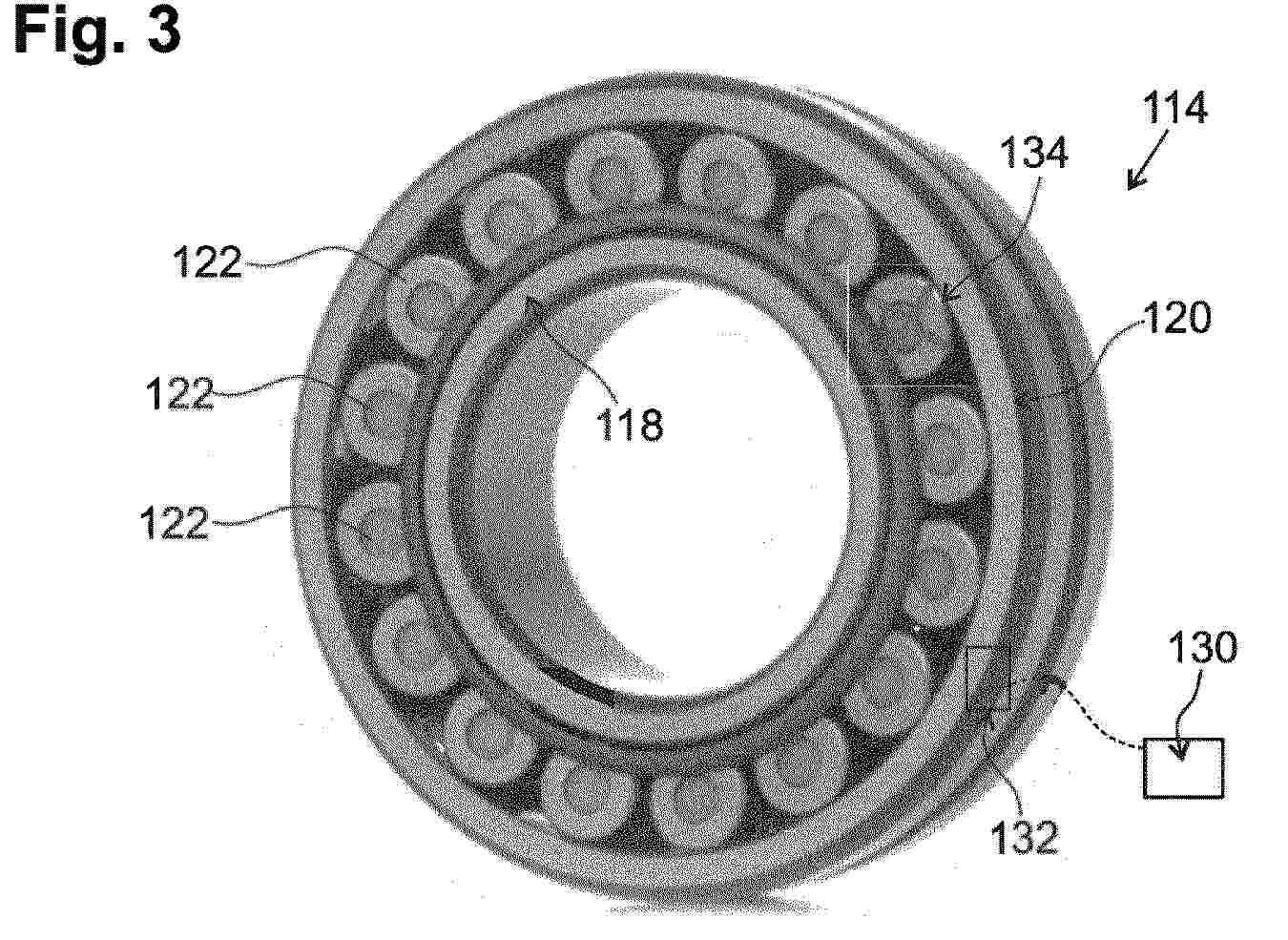
The invention concerns a method for operating a wind turbine (110), the wind turbine (110) comprising at least a roller bearing (114) for supporting the rotor shaft (160), wherein the roller bearing (114) comprises a bearing inner ring (118), a bearing outer ring (120) and a plurality of rolling elements (122, 124) being arranged between the bearing outer ring (120) and the bearing inner ring (118), the method comprising the following steps:- detecting, during operation of the wind turbine (110), a damaged rolling element (134) of the plurality of rolling elements (122, 124),- removing the damaged rolling element (134) from the rotor bearing (114),- operating the wind turbine (110) with the roller bearing (114) comprising the remaining rolling elements (122, 124).
Resumen de: WO2025056450A1
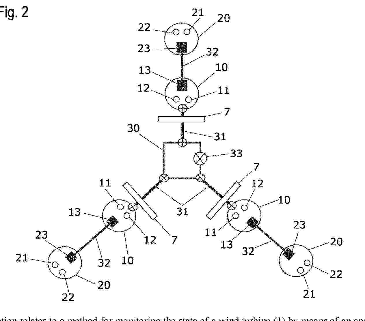
The invention relates to a method for monitoring the state of a wind turbine (1) by means of an analysis of vibrations of at least one rotor blade (6) of a rotor (4) of the wind turbine (1). The method comprises the following steps: - sensing vibrations of the at least one rotor blade (6) by means of at least one vibration sensor disposed in or on the rotor blade (6); - sensing at least one acceleration value and/or rotation rate value at at least one position of an acceleration sensor (11, 21) and/or gyrosensor (12, 22) which is disposed in or on the rotor blade (6); - determining an operating state of the rotor (4) and/or the rotor blade (6) on the basis of the at least one acceleration value and/or rotation rate value; - analyzing the vibrations of the at least one rotor blade (6) taking into account the operating state of the rotor (4) and/or the rotor blade (6). The invention also relates an assembly for monitoring the state of a wind turbine (1), comprising at least one vibration sensor for sensing vibrations of the at least one rotor blade (6), said vibration sensor being disposed in or on at least one rotor blade (6) of the wind turbine (1). The assembly is characterized in that an acceleration sensor (11, 21) and/or a gyrosensor (12, 22) is disposed in or on the rotor blade (6), and in that an evaluation device for carrying out a method of this type in order to analyze the sensed vibrations is provided.
Resumen de: EP4779150A1
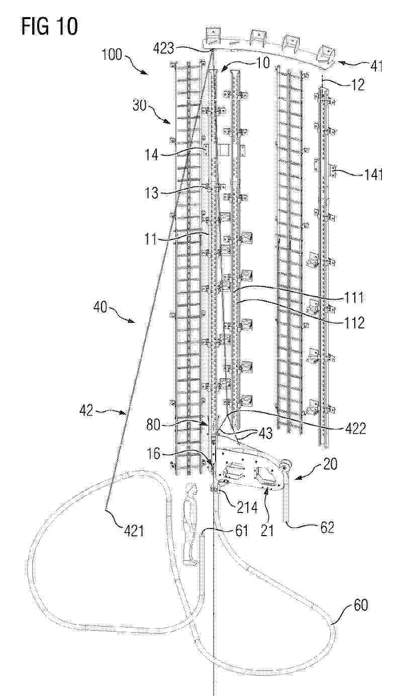
The present invention relates to a system (100) for handling a power cable (60) of a wind turbine comprising a cable support arrangement (20) adapted to support a portion of the power cable (60) and at least one guiding arrangement (10) being fixedly connectable or connected to at least one structure (51) within a wind turbine tower (50) and adapted to guide the cable support arrangement (20) along a linear track (12) provided by at least one guide rail (11). Furthermore, a wind turbine comprising the system (100) is disclosed.The disclosed system (100) for handling a power cable (60) is advantageous for improved operational safety, requires less installation space within the wind turbine tower (50) and provides improved operational flexibility.
Nº publicación: EP4778823A2 22/07/2026
Solicitante:
TRIVANE LTD [GB]
Trivane Ltd
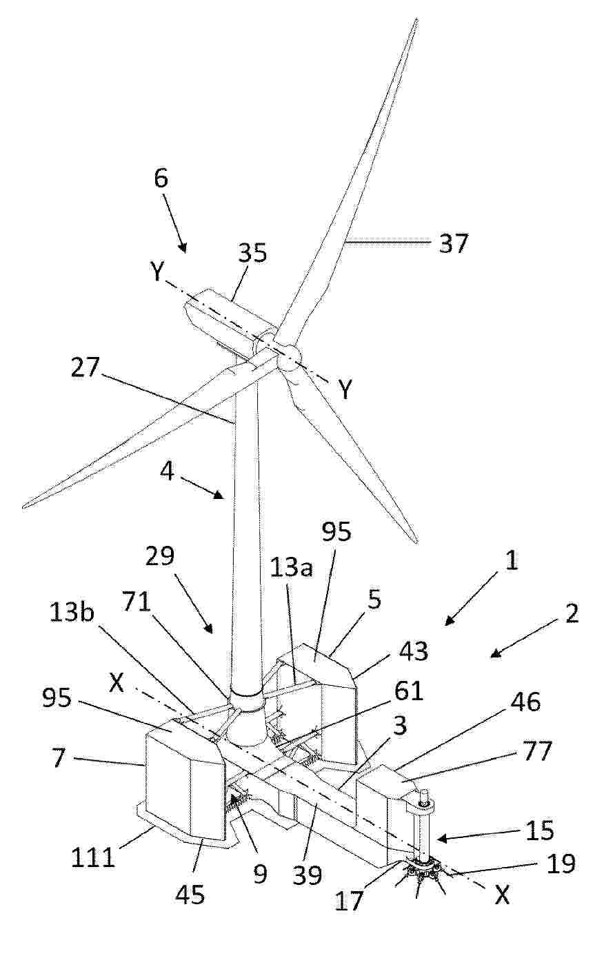
Resumen de: EP4778823A2
0001 A floating structure (1) having three buoyant bodies (3,5,7) for supporting a horizontal axis wind turbine (6) and wind turbine tower (27). The floating structure (1) is provided with a geostationary mooring system that permits it to weathervane in order to head the wind turbine (6) into the wind and has a wind turbine tower mount (29) for supporting the wind turbine tower (27). A central buoyant body (3) is located partially above water during assembly and tow out from port and is ballasted so that it is underwater when moored offshore, such that the floating structure (1) becomes a semi-submersible. The three buoyant bodies (3,5,7) are ship-shaped in form which reduces loads in the mooring system, and are made from stiffened flat plates, which are easier for many yards and fabrication shops to make, compared to cylindrical hulls.
 BOPI
BOPI
 Sede Electrónica