Si deseas distinguir tus productos, servicios o ambos de los de otra empresa, es posible que necesites una marca o nombre comercial. Descubre qué son, en qué consiste su procedimiento de registro y qué implica.

Información sobre los plazos de presentación de solicitudes de transformación de marcas de la Unión Europea en marca nacional española. Más información


Si tienes un nuevo dispositivo, producto o procedimiento que resuelva un problema técnico o tenga una ventaja práctica, existen distintas formas de protegerlo en España y en otros países. Descubre cómo hacerlo.

¿Tu innovación reside en la estética, la ornamentación o la apariencia de tu producto? Protégela mediante un diseño industrial. Descubre qué derechos confiere el registro y cómo realizar la tramitación.

Las indicaciones geográficas protegen el nombre de un producto originario de una zona geográfica, a la cual le debe una determinada calidad, reputación u otra característica. Descubre qué son, en qué consiste su procedimiento de registro y qué beneficios conceden.

Las patentes publicadas en todo el mundo son una valiosa fuente de información científica, técnica y comercial.

Si eres emprendedor/a o una empresa y quieres potenciar y mejorar la rentabilidad de tu negocio protegiendo de forma adecuada los activos intangibles de tu organización, en este espacio encontrarás lo necesario.


 467
resultados
467
resultados
 Última actualización
27/07/2026 [08:49:00]
Última actualización
27/07/2026 [08:49:00]


 Resultados 75 a 100 de 467

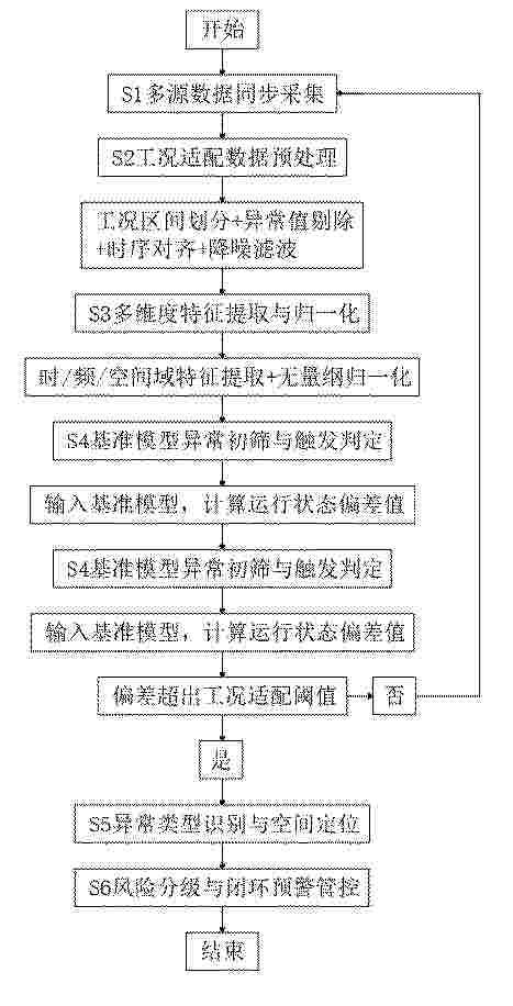
Resumen de: CN122447268A
本发明涉及风力发电叶片监测技术领域,且公开了一种风力发电机叶片异常监测方法及系统,方法包括:多源数据同步采集,匹配统一时间戳与编号完成原始数据归集;工况适配数据预处理,划分工况区间并适配规则得到标准化有效数据;多维度特征提取与归一化,得到标准特征数据集;基准模型异常初筛与触发判定,偏差超阈值则触发后续识别;异常类型识别与空间定位;风险分级与闭环预警管控,划分风险等级并输出预警与策略,同步将异常数据纳入模型增量学习数据集。通过多源数据与差异化预处理等保障数据有效性,两级监测架构提升响应实时性,全闭环体系实现差异化管控与模型迭代,提升监测适配性与可靠性。

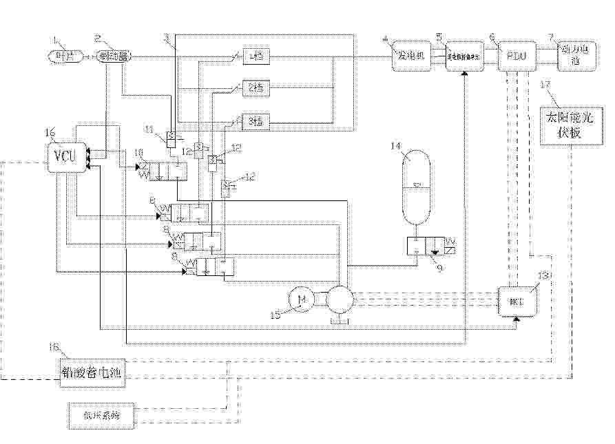
Resumen de: CN122447262A
本发明涉及发电的风力发电技术领域,提供一种用于风力发电调控的风速预测方法及系统,包括以下步骤:步骤1、实时获取垂直轴风力发电机的运行状态数据发送至主控制器MCU;步骤2、将步骤1的运行状态数据输入至主控制器MCU上预设的物理与数据融合的混合预测模型中算出预测瞬时转矩;步骤3、将步骤2主控制器MCU得到的预测瞬时转矩和预测转速交互至变流器控制单元VCU,变流器控制单元VCU计算最优传动速比,并且变流器控制单元VCU根据最优传动速比通过控制叶片连接的多档变速箱换挡调控以使发电机运行于发电高效区实现最大功率点跟踪调控。本发明解决现有垂直轴风力发电机反馈控制严重迟滞、风能捕捉效率低的问题。
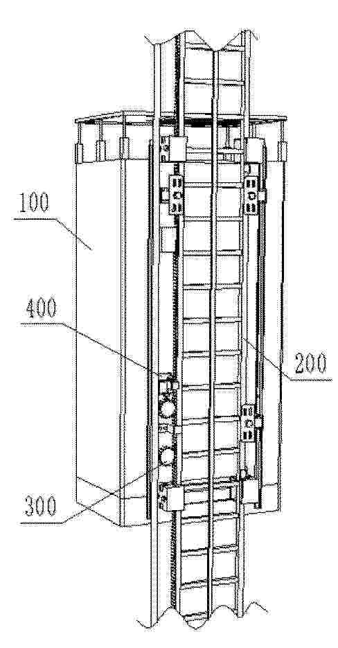
Resumen de: CN122444051A
本发明提出了一种用于风力发电施工的带自动清理与润滑的升降结构,涉及风力发电施工设备领域,包括升降机本体、齿条爬梯、传动齿轮、安装基体、容纳罩、清理部件、负压产生部件、过滤部件、联动驱动机构和供油组件。联动驱动机构包括由负压产生部件进气气流驱动的气流驱动件,以及将气流驱动件的旋转运动转换为至少两个不同方向往复直线运动的运动转换机构。运动转换机构的一个输出端驱动清理部件沿齿条爬梯轮齿横向往复移动以进行清理;另一个输出端连接供油组件的活塞式储油单元的活塞,驱动活塞往复运动,将润滑油通过滴油管路滴至传动齿轮。该结构实现了在升降运行过程中同步、自动地完成齿条爬梯的清理除尘与传动齿轮的润滑。
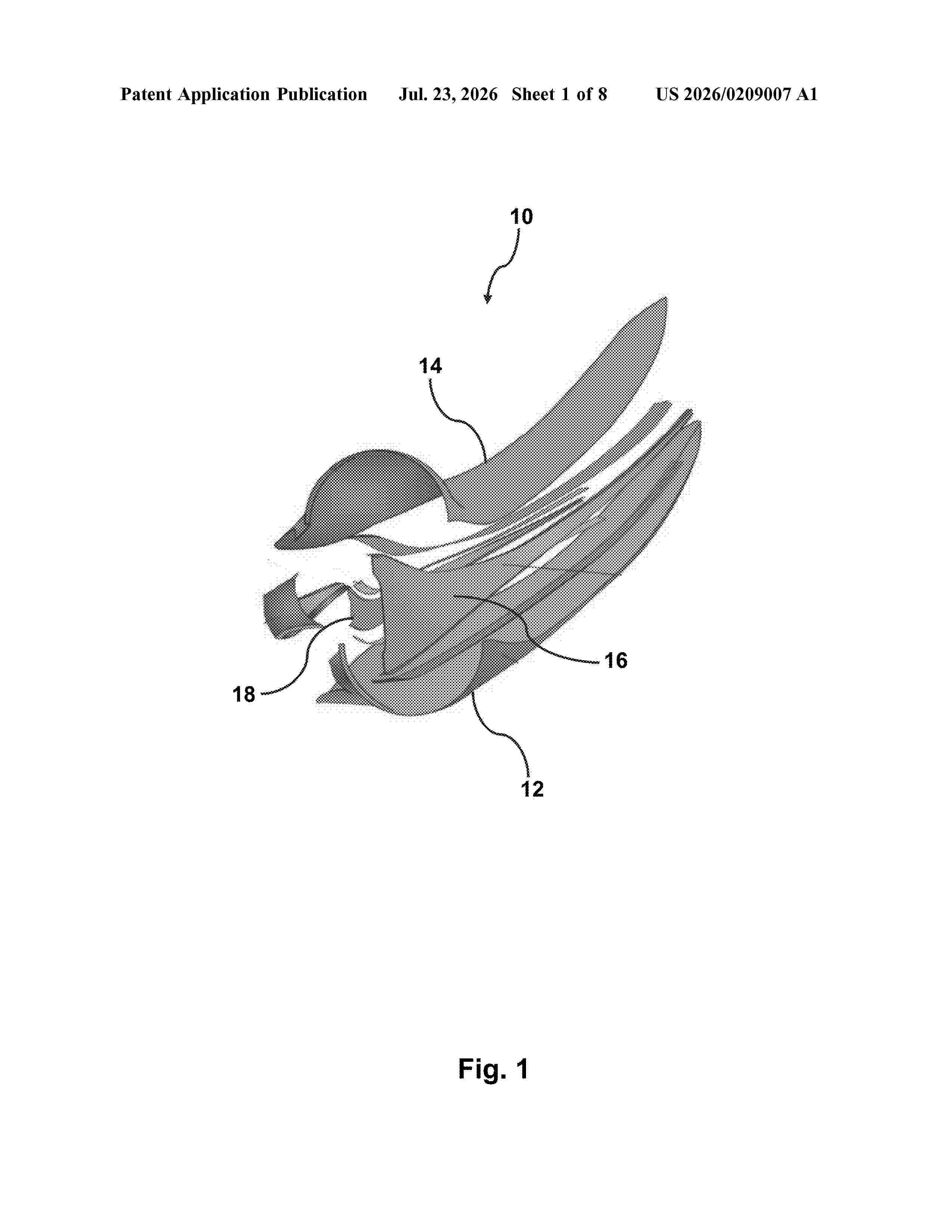
Resumen de: CN122447254A
本发明涉及气流产生技术领域,提供一种叶轮组件及风力机。其中,叶轮组件包括:轮毂;多组叶片,分布于所述轮毂的外周且连接所述轮毂,每组所述叶片均包括前翼片和后翼片,所述后翼片位于所述前翼片的压力面所在一侧,且所述前翼片和所述后翼片之间存在间隙。根据本申请实施例的叶轮组件,后翼片可以避开前翼片的气流干扰影响,防止振动和噪声,且后翼片可以提升前翼片尾缘位置气流的升力,以提升叶轮组件的效率。并且,由于后翼片设置在前翼片的压力面,进而后翼片可以对前翼片压力面的空间进一步利用,提升叶轮组件的空间利用率,在不明显增加叶轮组件占用空间和重量的前提下,提升叶轮组件的升力。
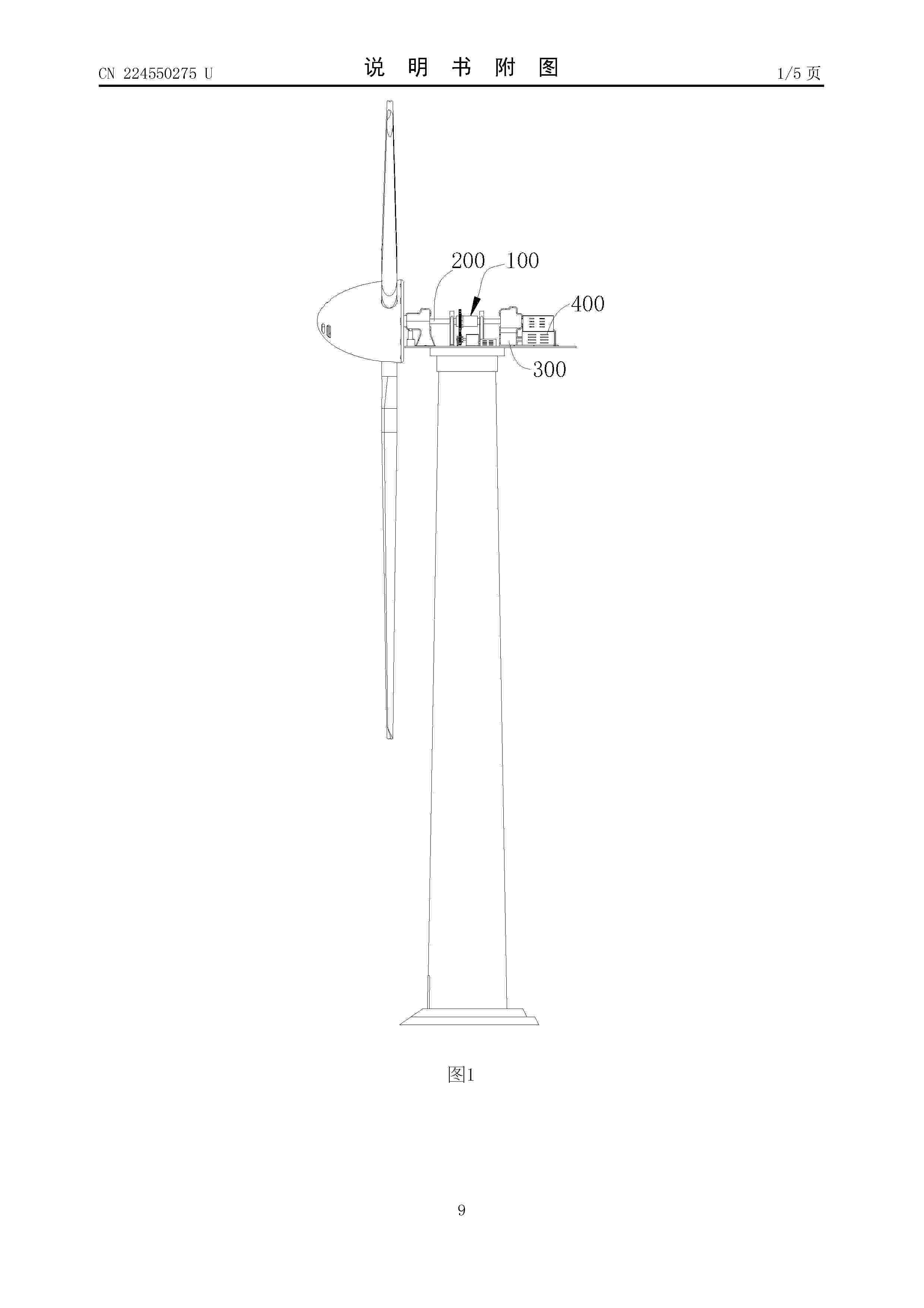
Resumen de: CN224550275U
本实用新型公开了一种限速装置及风力发电机组,该限速装置安装于风力发电机组并与主轴连接,包括轴套、转筒、连接组件和减速组件。其中,轴套固定套设于主轴,沿轴套的周向开设有啮合槽;转筒套设于主轴,且转筒与主轴同轴设置,转筒内部形成有容置腔,轴套容置于容置腔,主轴穿设于容置腔;连接组件安装于转筒的内壁,连接组件包括驱动结构和啮合块,驱动结构用于驱动啮合块伸入啮合槽;减速组件包括齿轮组、从动轴和发电机组,齿轮组包括相互啮合的主动齿轮和从动齿轮,主动齿轮套设于转筒,从动轴与从动齿轮同轴连接,从动轴与发电机组连接。本实用新型提供的限速装置具有能够降低主轴转速和回收主轴的动能等优点。
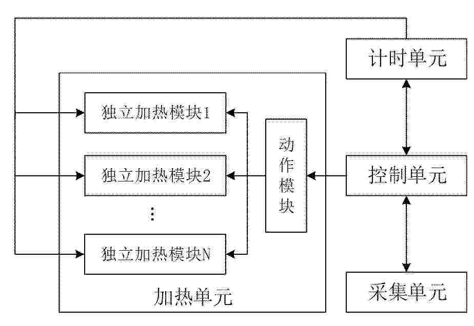
Resumen de: CN122447272A
本发明公开了一种基于智能感知的风电机组叶片阶梯式除冰系统及方法,涉及风电设备除冰技术领域。系统中采集单元实时采集风电机组各叶片的环境信息;控制单元对环境信息进行判断,利用阶梯式加热启动逻辑根据预设时间间隔依次发送加热启动信号;动作模块根据加热启动信号按序阶梯式启动各独立加热模块对叶片进行加热;计时单元统计记录加热时长,在加热时长大于预设时长时发送停止请求信号;控制单元接收停止请求信号后发送加热停止信号,动作模块关闭对应的独立加热模块。本发明通过多叶片阶梯式分时启停加热和独立计时闭环管控,实现了叶片覆冰快速精确去除,保证风电机组正常运行,提高了发电效率,降低了叶片的维护成本。
Resumen de: US20260213682A1
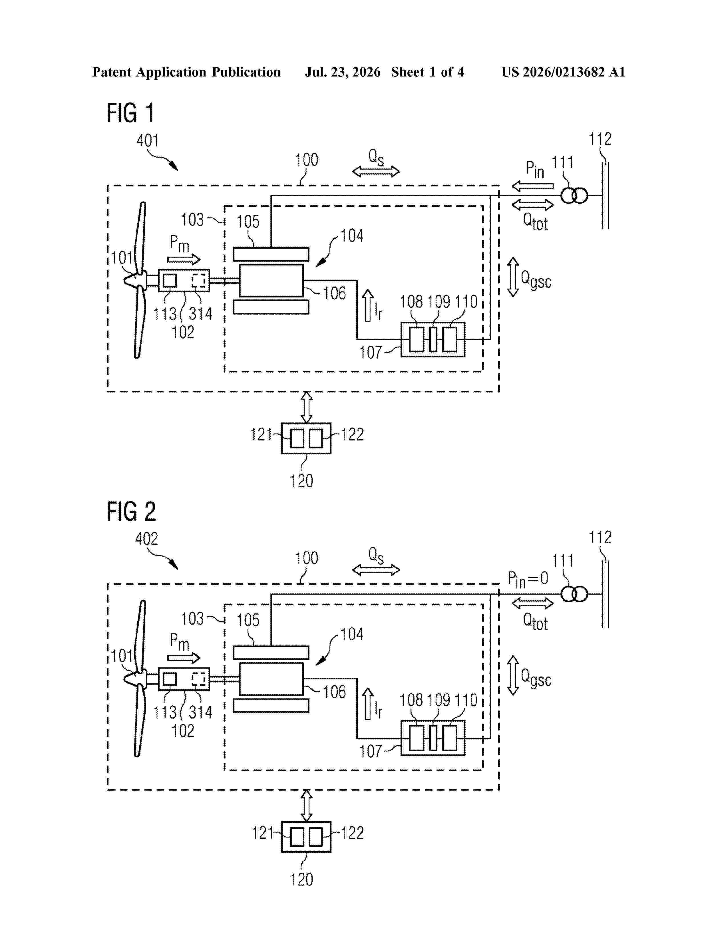
A method of operating a wind turbine including a wind turbine rotor and an electrical power system including a doubly-fed induction generator mechanically coupled to the wind turbine rotor, wherein the electrical power system is configured to exchange electrical power with a power grid. The method includes obtaining a grid requirement for the wind turbine to exchange reactive power with the power grid, wherein providing the reactive power in accordance with the grid requirement by the electrical power system requires the electrical power system to consume an active power amount, and operating the generator as a variable-speed rotating condenser to provide at least a part of the reactive power to the power grid.
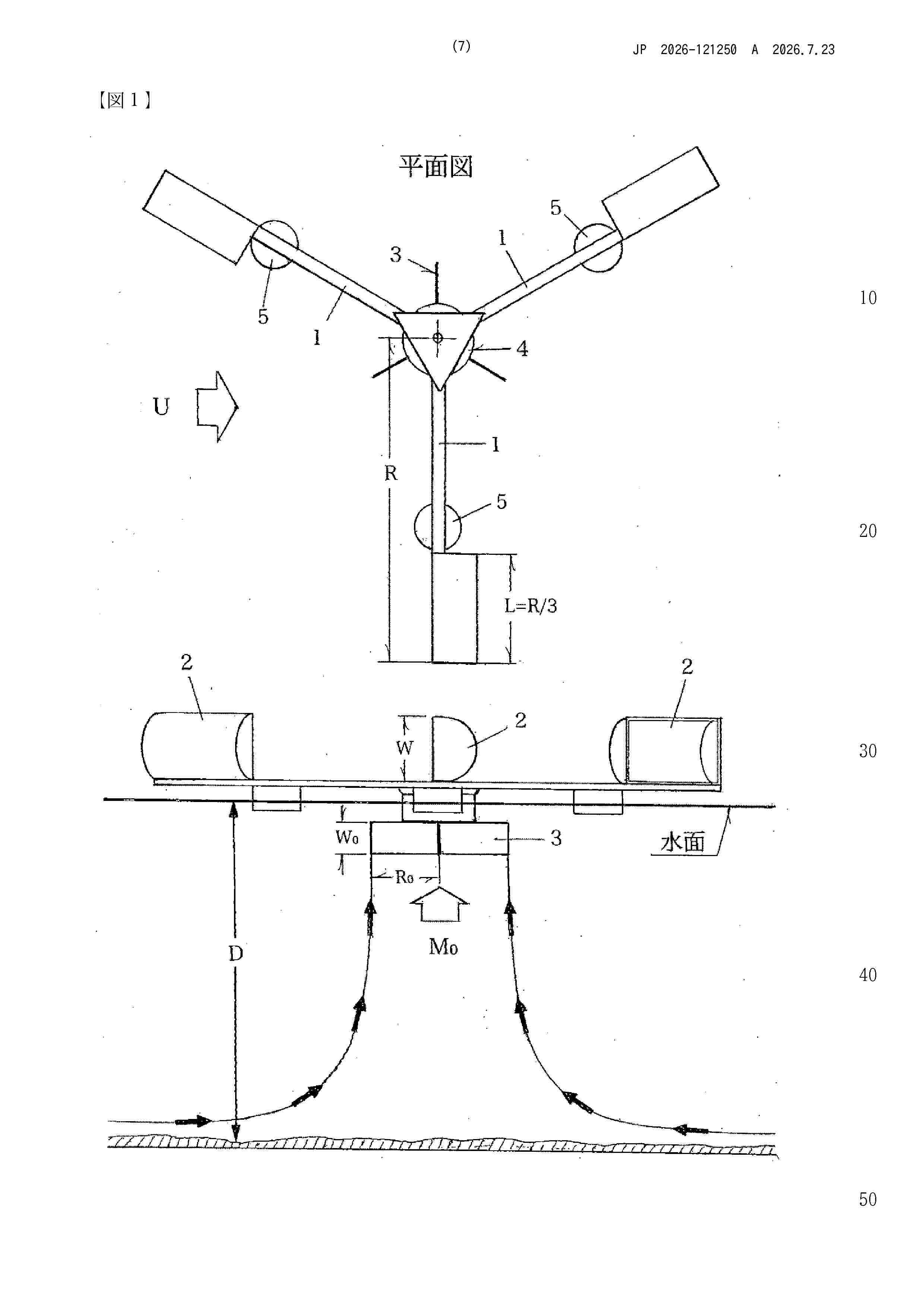
Resumen de: JP2026121250A
【課題】わずかな風力で水底から引き上げた水を水面方向に広げるようにした風力式バイオファンを提供する。【解決手段】水掻き板を回すパワーはアームの長さとそアームに作用する風力の積に比例するという特性を活かして、風力式新型バイオファンの設計に必要な四つの基本式を導入し、広大な水域の光合成を活発にして生じた膨大な酸素で湖や湾や海洋を大漁場に再生し、海洋の酸性化も抑制できる新型バイオファンの開発を可能にした。【選択図】図1
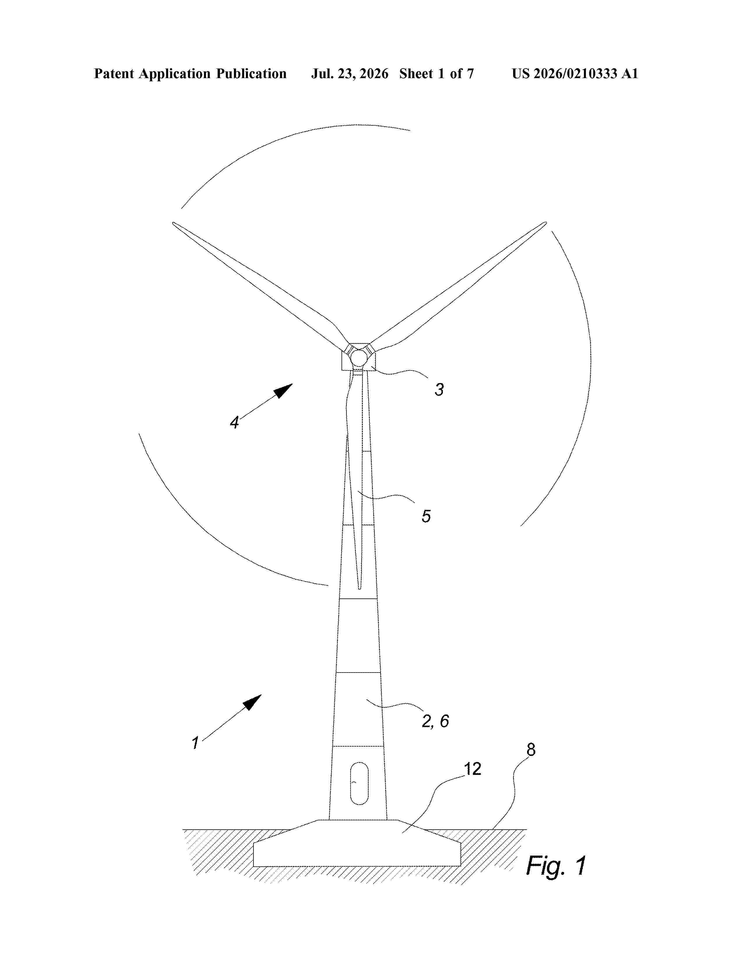
Resumen de: US20260210333A1
A method for assembling a tower part of a wind turbine. The method includes placing an elongated tubular tower section of the wind turbine so that it is laying down and so that at least a part of an outer elongated surface of the tower section is supported by an underlying surface and forming an electrical module. The electrical module includes at least one electronic subsystem of the wind turbine. The method further includes transporting the electrical module into the elongated tubular tower section and tilting the electrical module substantially 90 degrees, and connecting the electrical module to at least two opposing inside surfaces of the elongated tubular tower section.
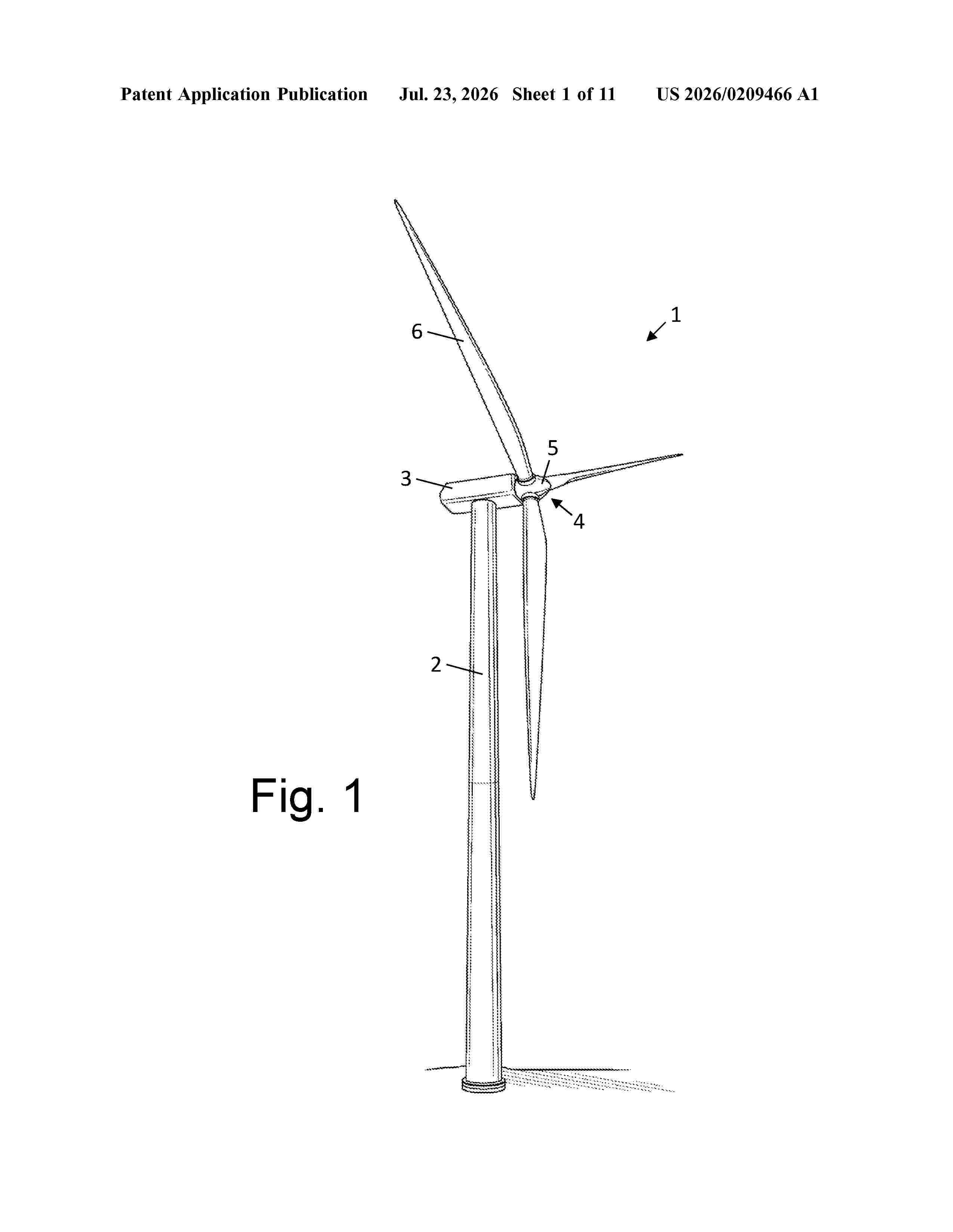
Resumen de: US20260209466A1
A method of transporting pieces of composite material, the pieces of composite material comprising reinforcement fibres embedded in a matrix material. The method comprises: loading the pieces into a container; and then transporting the container, the method further comprising softening the matrix material before transporting the container by treating the pieces with a liquid, wherein the liquid transforms the pieces into softened pieces, the softened pieces form a pile of softened pieces in the container, and at least some of the pieces change shape after they have been softened.
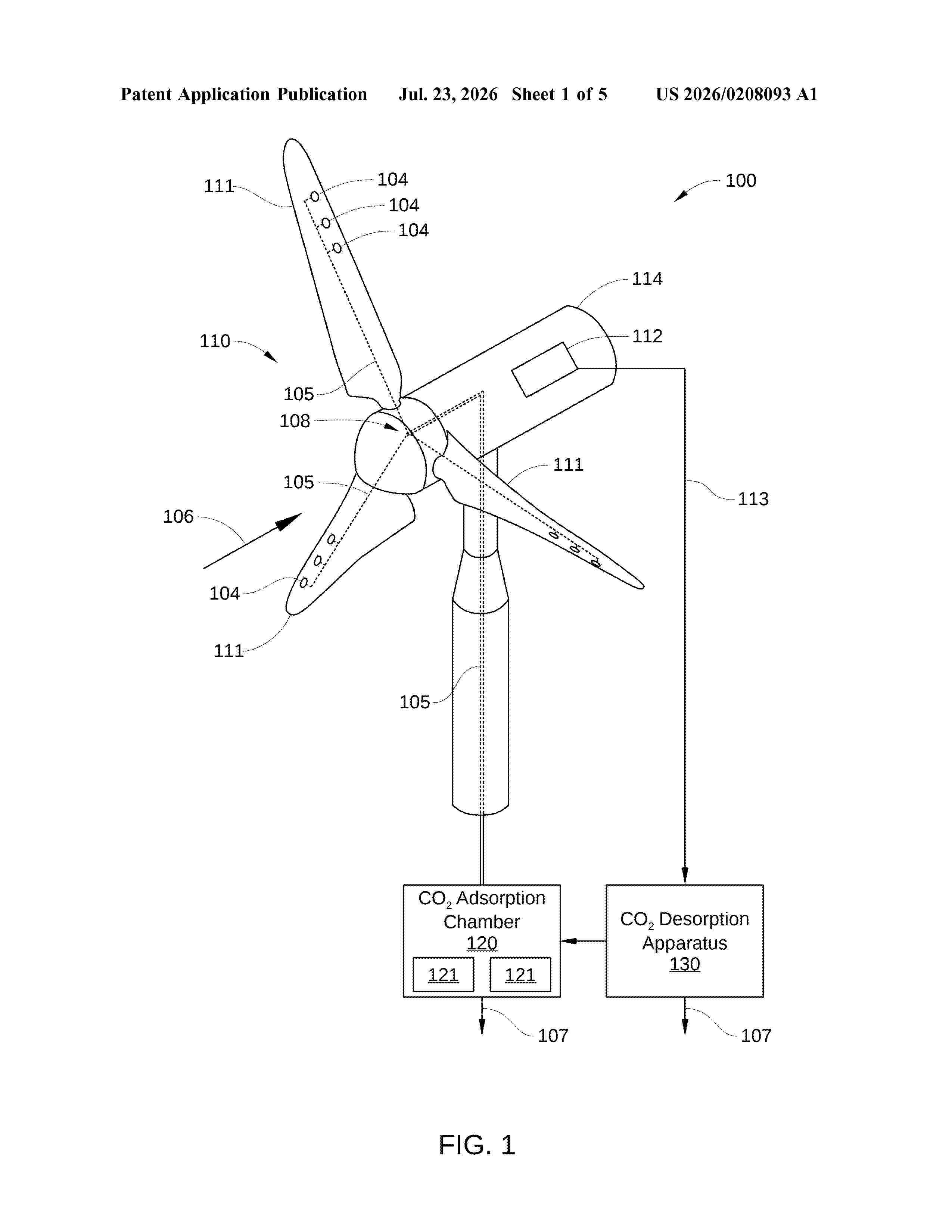
Resumen de: US20260208093A1
According to various embodiments, a direct air capture system includes: a wind turbine that includes at least one blade that includes one or more openings, wherein, in operation, first air flows across the at least one blade, causing the wind turbine to generate electrical energy, and causing the one or more openings to receive second air; a conduit that fluidly couples the one or more openings to a carbon dioxide (CO2) adsorption chamber that includes one or more amine-based CO2 adsorbers, wherein, in operation, the CO2 absorption chamber receives the second air via the one or more openings; and a carbon desorption apparatus that desorbs CO2 from the one or more amine-based CO2 adsorbers.
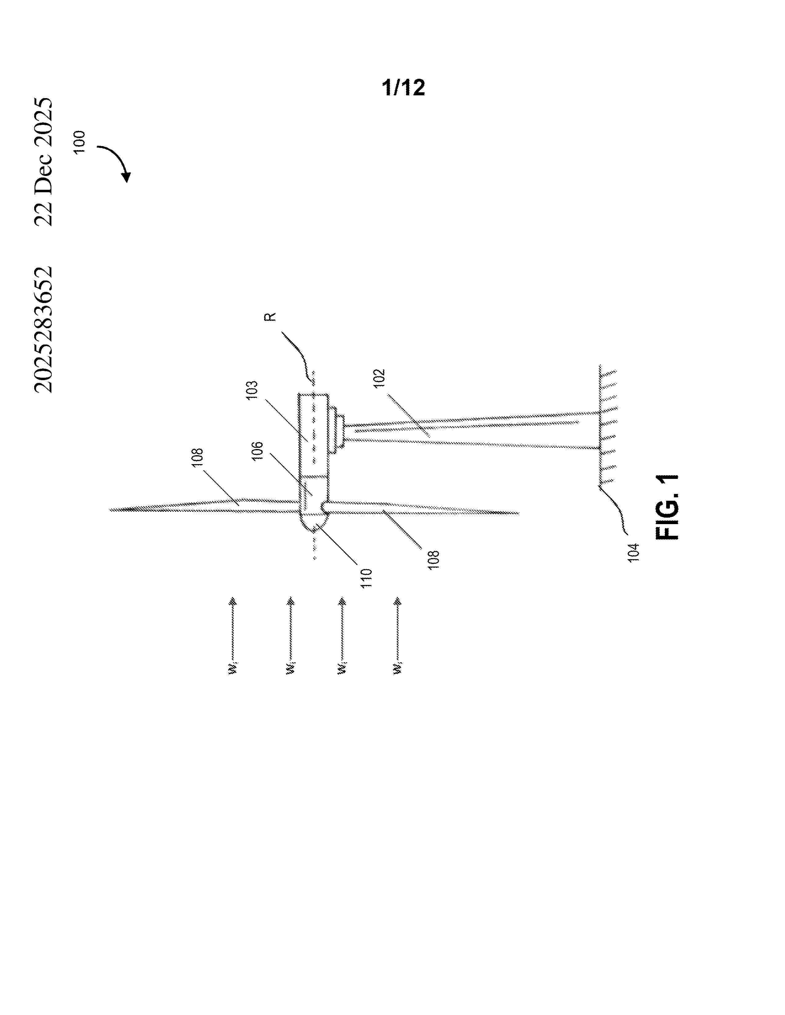
Resumen de: AU2025283652A1
- 60 - CAN_DMS: \1008757416 A structure is proposed for traversing a fluid environment and reducing the interference of the fluid flow vector at a trailing edge of the structure. The structure comprises an elongate body having a root, a wingtip, a leading edge and the trailing edge. The structure has a plurality of flexible projections positioned along the trailing edge extending from a base to a tip. The plurality of flexible projections bend to conform to a curvature of the fluid flow vector at the trailing edge and have a first resonant frequency above an oscillating force generated by the fluid flow vector. - 60 - ec e c - - ec e c
Resumen de: US20260209007A1
A lifting yoke for placing and positioning items on an inner surface of a shell half of a wind turbine blade is provided. The lifting yoke includes—a longitudinal beam, —a plurality of landing pads positioned along the longitudinal beam configured for standing on the inner surface of the shell half. Also included is: —a plurality of global adjustment arrangements for pivoting the plurality of landing pads, wherein the landing pads include—a contact surface for being in contact with the inner surface, and —a local adjustment arrangement for adjusting a curvature of the contact surface to the curvature of the inner surface.
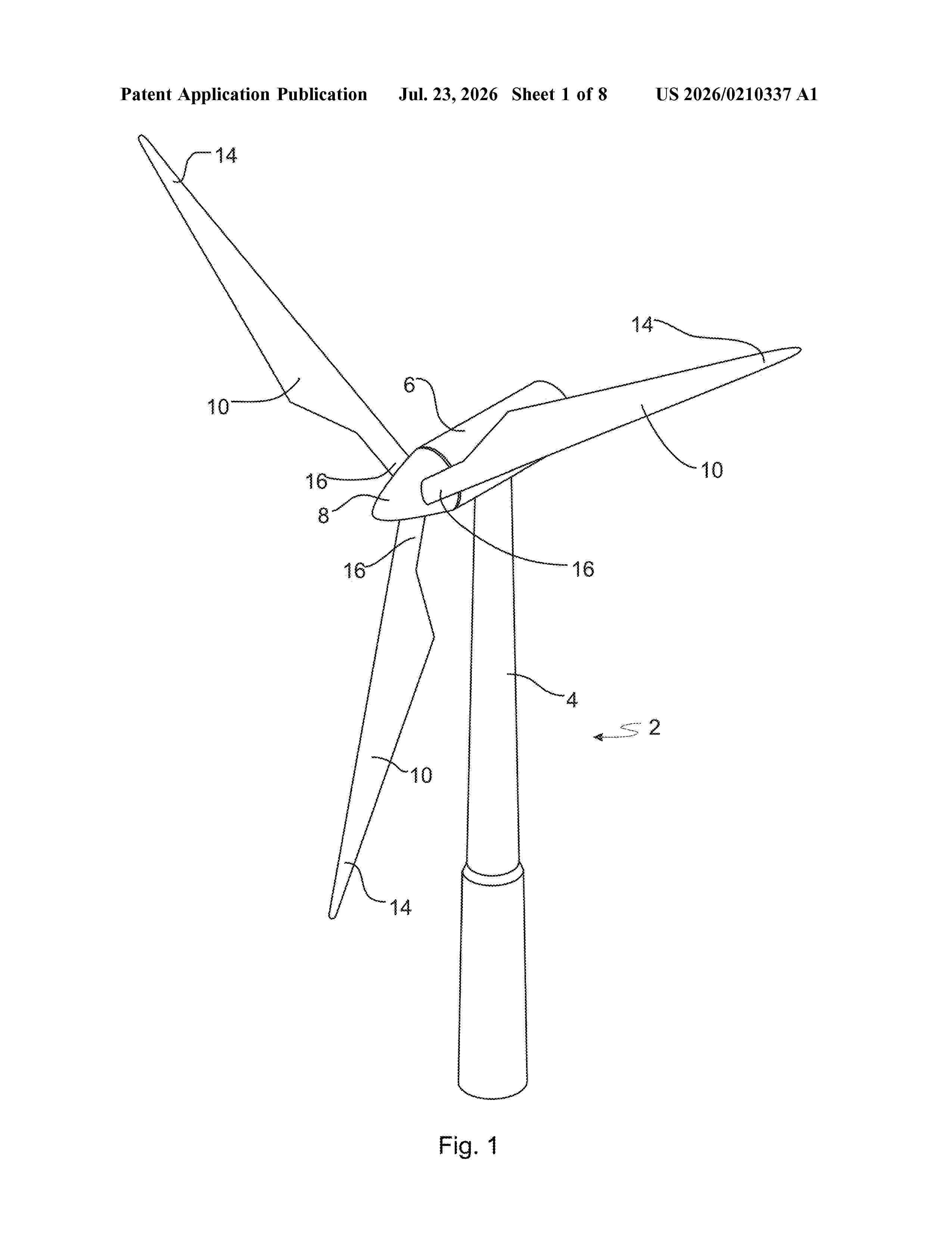
Resumen de: US20260210337A1
A wind turbine blade includes a leading-edge heating element extending along at least a portion of the leading edge and is configured for deicing a corresponding portion of an exterior surface of the leading edge. The wind turbine blade also includes a first plurality of heating strips, each heating strip extending in a substantially spanwise direction of the wind turbine blade and the first plurality of heating strips forming part of a first shell portion of the wind turbine blade. In the first shell portion is the pressure side shell portion or the suction side shell portion, the first plurality of heating strips being spaced apart from one another and from the leading-edge heating strip in a chordwise direction, each heating strip having a first end and a second end, the first end being closer to the tip end, and each heating strip including carbon-fibre yarn and/or tow material.
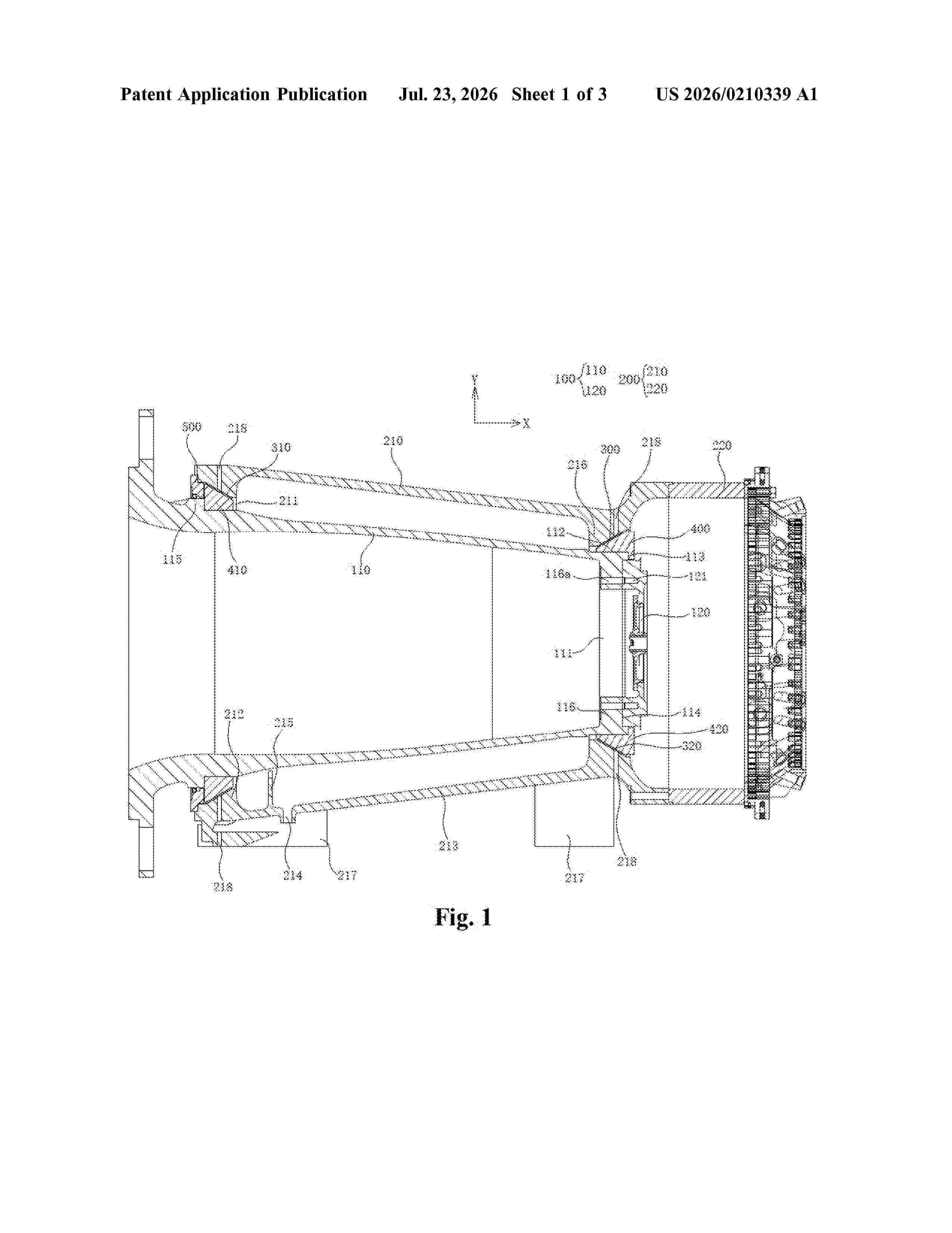
Resumen de: US20260210339A1
0000 Embodiments of the present application provide a transmission system and a wind turbine, the transmission system is used for the wind turbine, and the transmission system includes: a transmission section including a first transmission shaft and a second transmission shaft that are distributed along a first direction and fixedly connected to each other; a fixation section fitting around an outside of at least part of the transmission section, in which the fixation section includes a bearing base and a gear box body that are distributed along the first direction and fixedly connected to each other; and a bearing provided between the transmission section and the fixation section, in which the transmission section is rotatable relatively to the fixation section through the bearing. The transmission system according to the embodiments of the present application has advantages, for example, stable transmission ratio, simple structure, and easy maintenance.
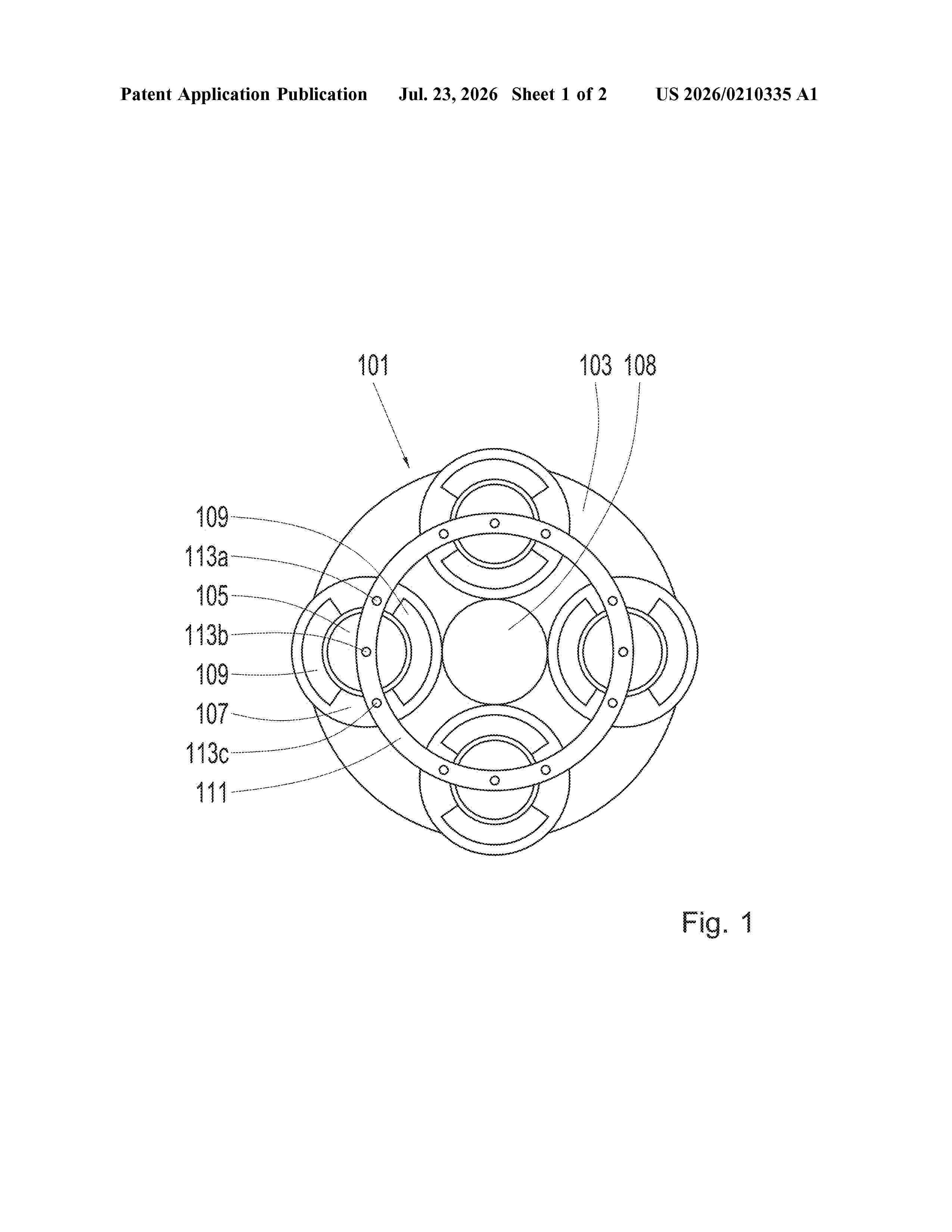
Resumen de: US20260210335A1
A drive arrangement for a wind turbine includes a planetary carrier and a planetary gear. The planetary gear is rotatably mounted in the planetary carrier. The planetary carrier has at least one lubricant line which opens into a space between the at least one planetary gear and a side plate of the planetary carrier.
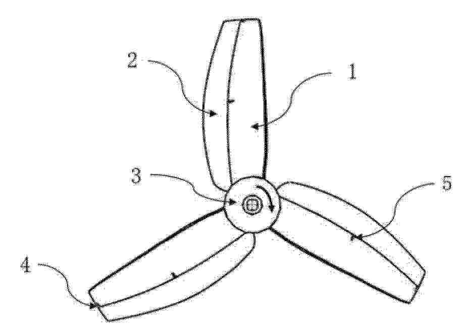
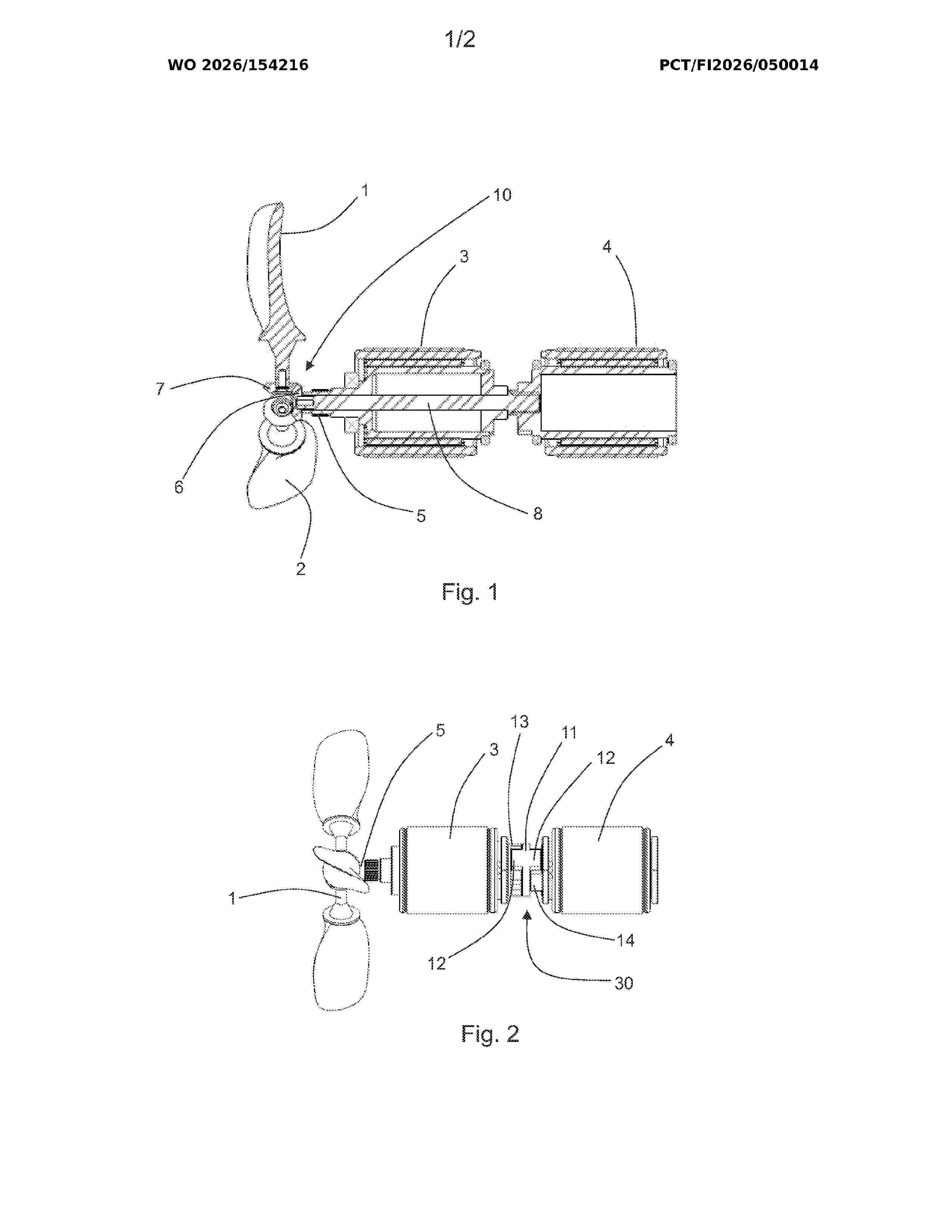
Resumen de: WO2026154216A1
The object of the invention is an arrangement for adjusting the pitch angle of a propeller (1) in an electric propulsion system, the system comprising two electric motors (3, 4), which motors are connected to a propeller (1) that is used for forward drive, reverse drive and also, if necessary, as a generator for recharging accumulators, whereby the propeller (1) comprises a propeller hub and at least two blades (2) fastened to the hub of the propeller ( 1 ), in which case the first shaft (5) of the first electric motor (3) is hollow and its end is connected to the blades (2) of the propeller (1) by means of a bevel gear (6) of the end of the first shaft (5) of the first electric motor (3) and the bevel gears (7) of the blades (2) of the propeller (1), and in that the electric motors (3, 4) are situated concentrically one after the other, in which case the second shaft (8) of the second electric motor (4) passes through the hollow first shaft (5) of the first electric motor (3) and is connected to the propeller (1) for rotating the propeller, and in that the arrangement also comprises motor controllers for driving and adjusting the electric motors (3, 4) as well as position sensors for monitoring the position ratio, i. e. the angular difference or phase difference, of the electric motors (3, 4).
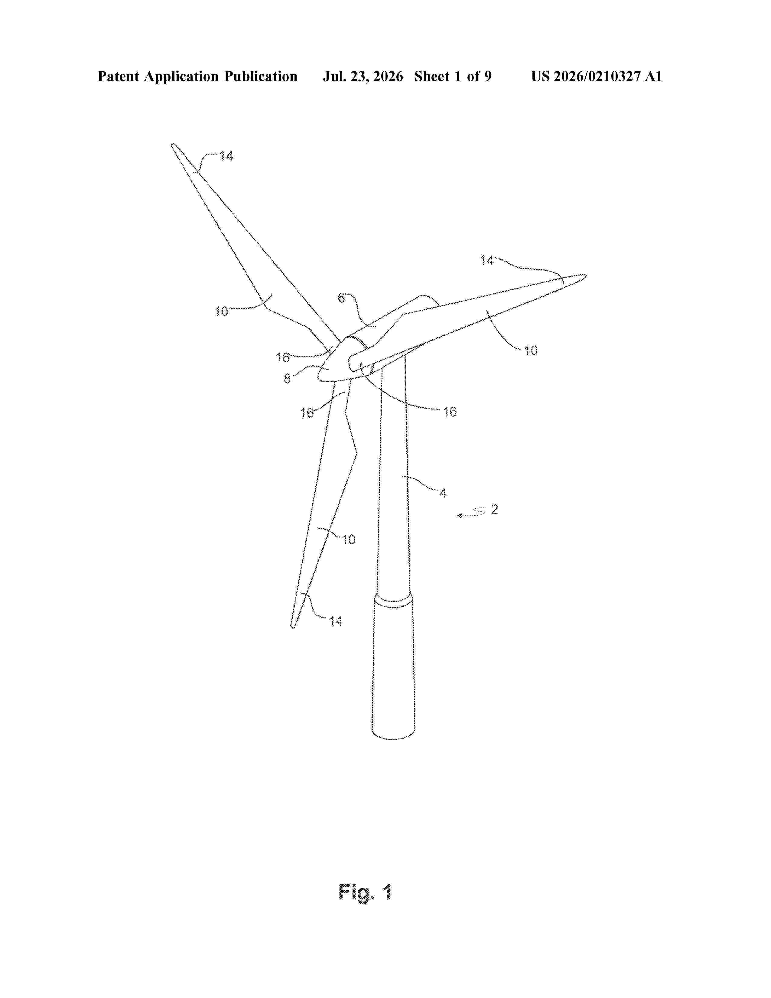
Resumen de: US20260210327A1
The present invention relates to a wind turbine blade having a profiled contour including a pressure side and a suction side and a leading edge and a trailing edge with a chord having a chord length extending therebetween, the wind turbine blade extending in a spanwise direction between a root end and a tip end, wherein the wind turbine blade comprises a trailing edge section defined between a first trailing edge section end and a second trailing edge section end, wherein the trailing edge section comprises a plurality of slits, including: a first plurality of slits extending a first distance from the first trailing edge section end toward the second trailing edge section end, and a second plurality of slits extending a second distance from the first trailing edge section end toward the second trailing edge section end, wherein the second distance is smaller than the first distance, andwherein the trailing edge section is part of the wind turbine blade or wherein the trailing edge section is part of a trailing edge panel attached to the wind turbine blade.
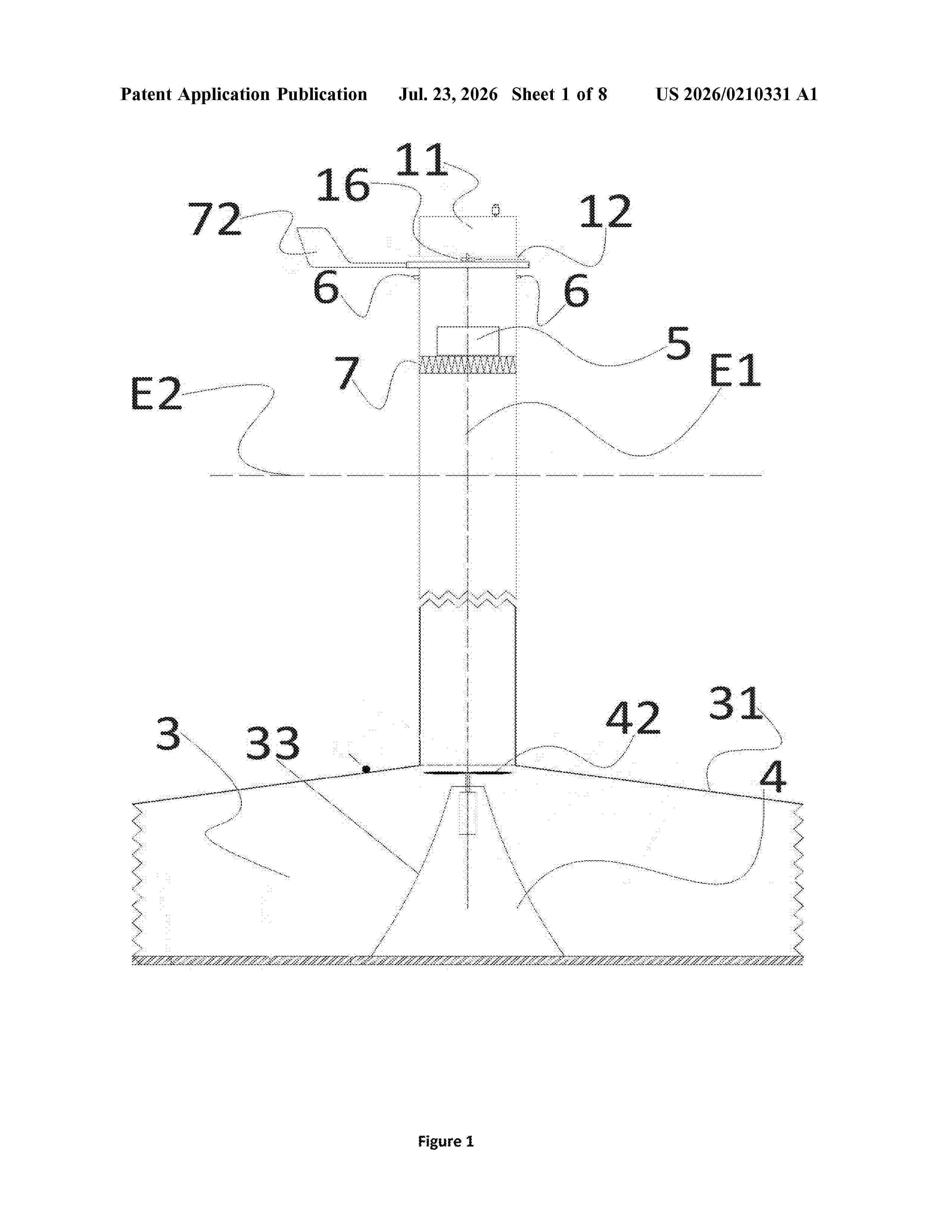
Resumen de: US20260210331A1
0000 Disclosed herein is a hybrid solar chimney to provide energy gain, including at least one chimney where the suction-draft process (vacuum effect) results in air whose density is reduced by the horizontal wing and at least one greenhouse to heat the air in the chimney.
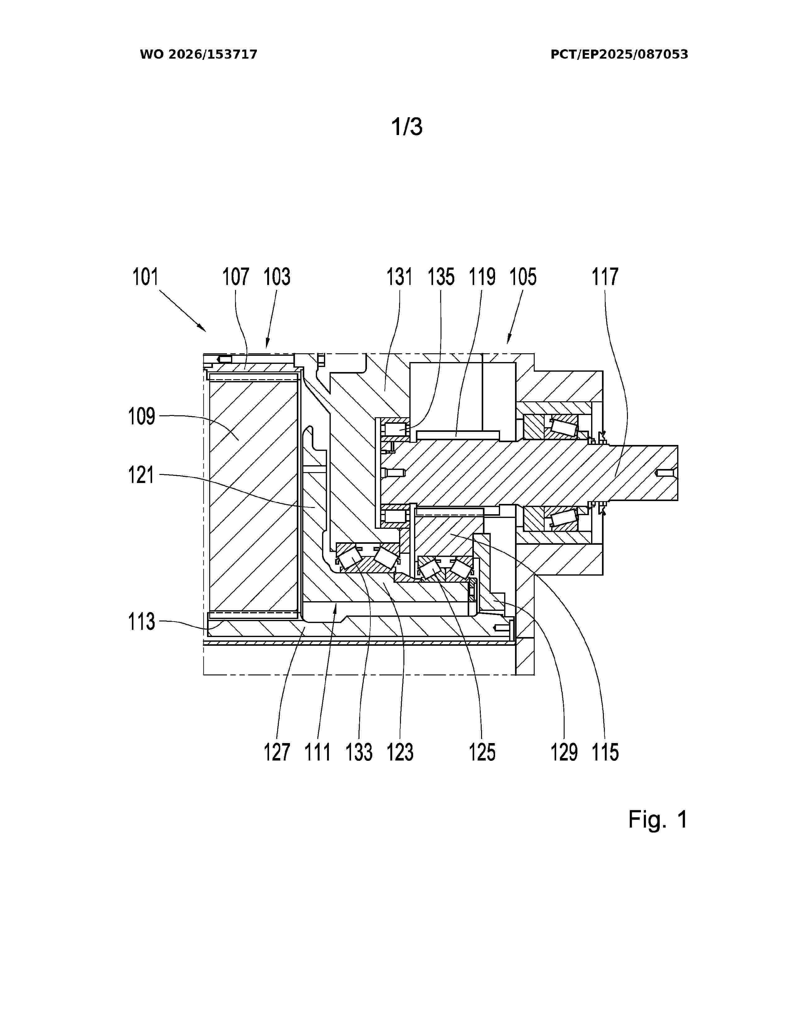
Resumen de: WO2026153717A1
The invention relates to a drive arrangement (101) for a wind turbine, comprising a rotatably mounted planet carrier (111) and a spur gear (115) arranged coaxially with the planet carrier (111). The spur gear (115) is rotatably mounted on a hub (123) of the planet carrier (111).
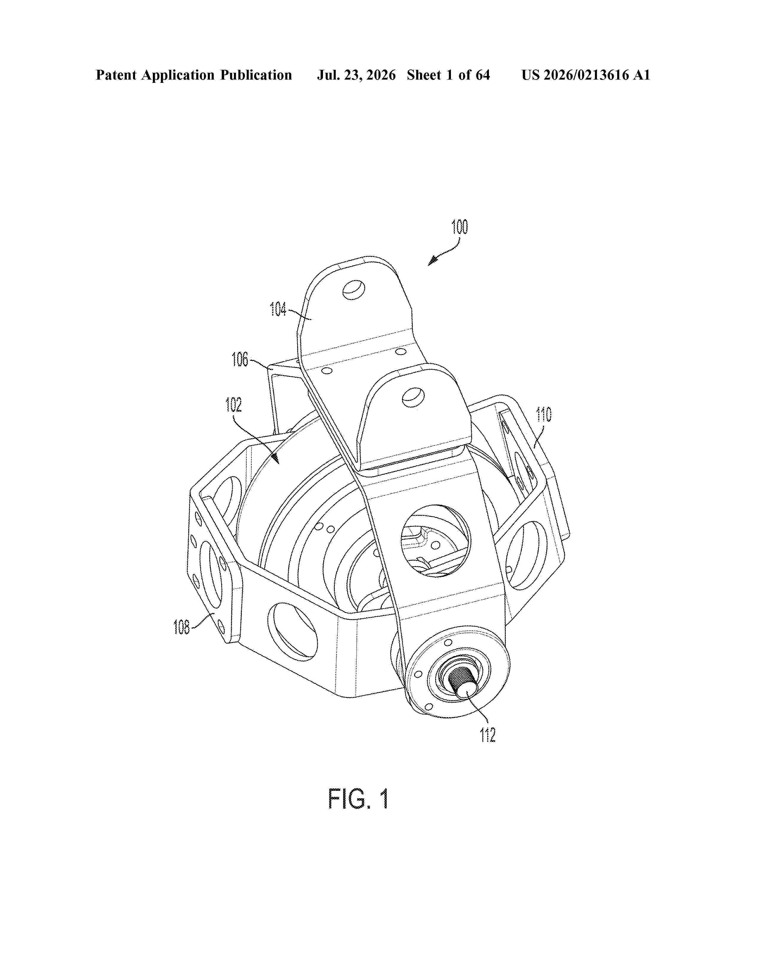
Resumen de: US20260213616A1
0000 An energy conversion device may include a shaft including a first portion and a second portion wherein the first portion of the shaft is configured to rotate relative to the second portion of the shaft. A rotor may be coupled to the first portion of the shaft and a stator may be coupled to the second portion of the shaft. A first one-way bearing may be coupled to the first portion of the shaft and configured to transfer rotational input to the first portion of the shaft in a first direction. A second one-way bearing may be coupled to the second portion of the shaft and configured to transfer rotational input to the second portion of the shaft in a second direction opposite the first direction.
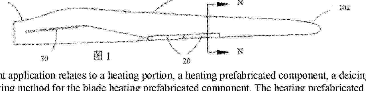
Resumen de: AU2024415751A1
The present application relates to a heating portion, a heating prefabricated component, a deicing apparatus, a blade, a wind turbine, and a mounting method for the blade heating prefabricated component. The heating prefabricated component comprises a heating portion and a first protection portion; the first protection portion is stacked on the heating portion and covers the heating portion, the heating prefabricated component is connected to the blade via the heating portion, and the heating portion is configured to provide heat to the blade.
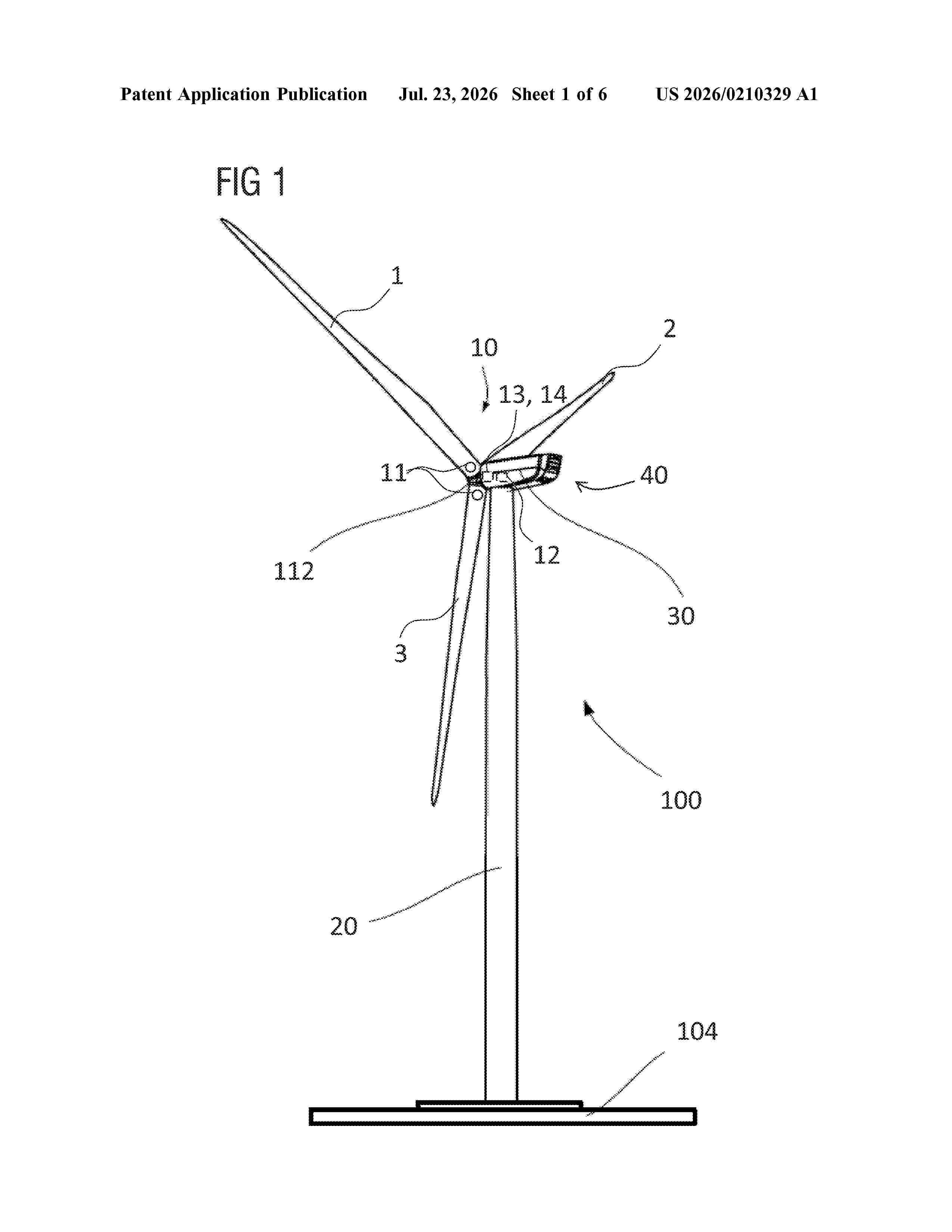
Resumen de: US20260210329A1
0000 A method is for operating a wind turbine having a rotor with at least one rotor blade and a rotor speed setting system for setting the speed of rotation of the rotor. The method includes a step of providing first information which is representative for whether an edge-wise movement of at least one rotor blade exceeds a threshold while the rotor is rotating. If this is the case, an output signal is generated, wherein the output signal is configured to cause the rotor speed setting system to change the speed of rotation of the rotor without stopping rotation of the rotor in order to reduce the edge-wise movement of the at least one rotor blade.
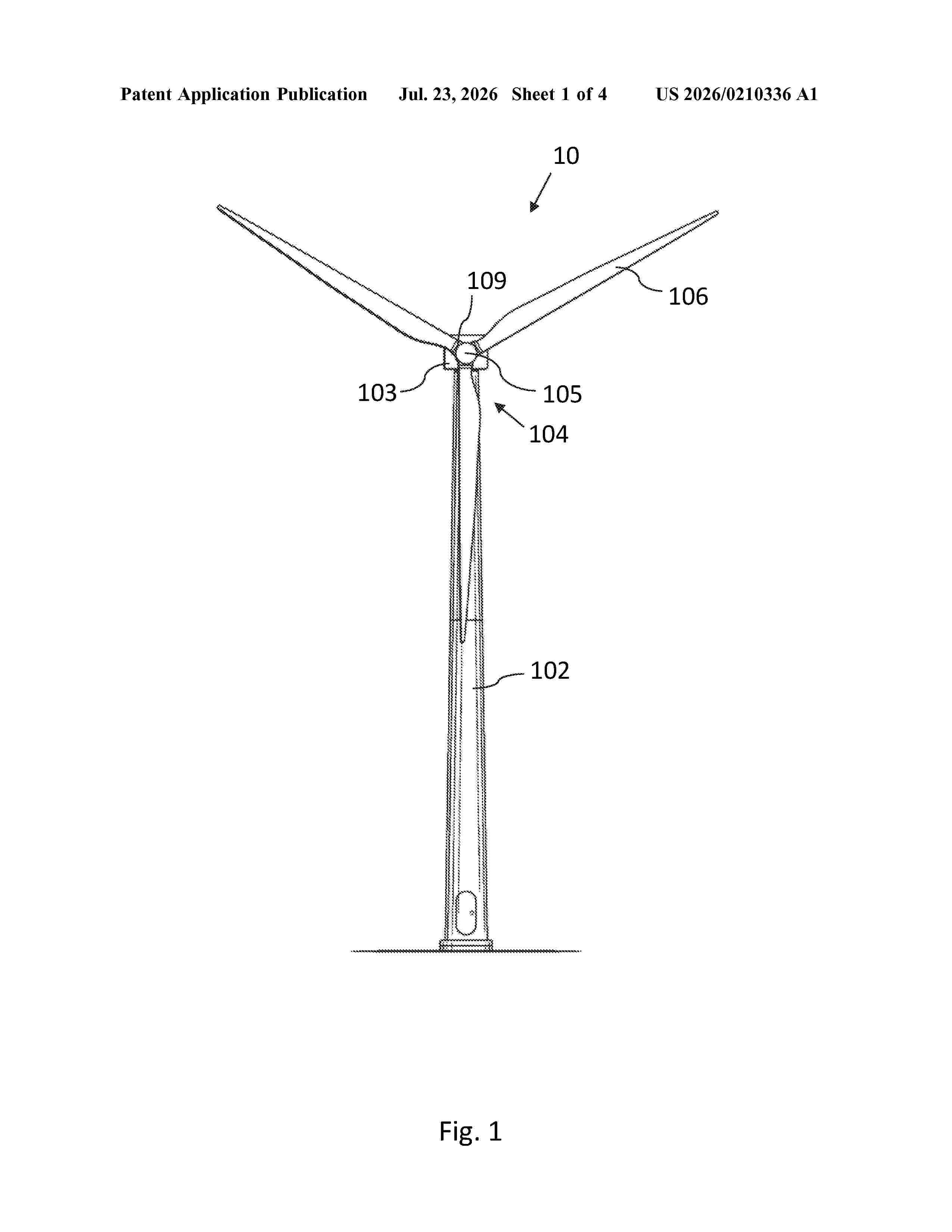
Resumen de: US20260210336A1
Aspects of the invention relate to a method of controlling a wind turbine comprising a rotor and a plurality of rotor blades. The method comprises: receiving a plurality of blade flap load signals indicative of measured flap loading on respective rotor blades, each blade flap load signal being received from a blade flap load sensor of a respective rotor blade; determining an average blade flap load signal based, at least in part, on the plurality of blade flap load signals; and determining a maximum thrust level for a thrust limit controller based on the average blade flap load signal and a reference load value that is indicative of a maximum allowable variation of the average blade flap load signal from a normal value.
Nº publicación: US20260210338A1 23/07/2026
Solicitante:
NABRAWIND TECH S L [ES]
NABRAWIND TECHNOLOGIES, S.L.
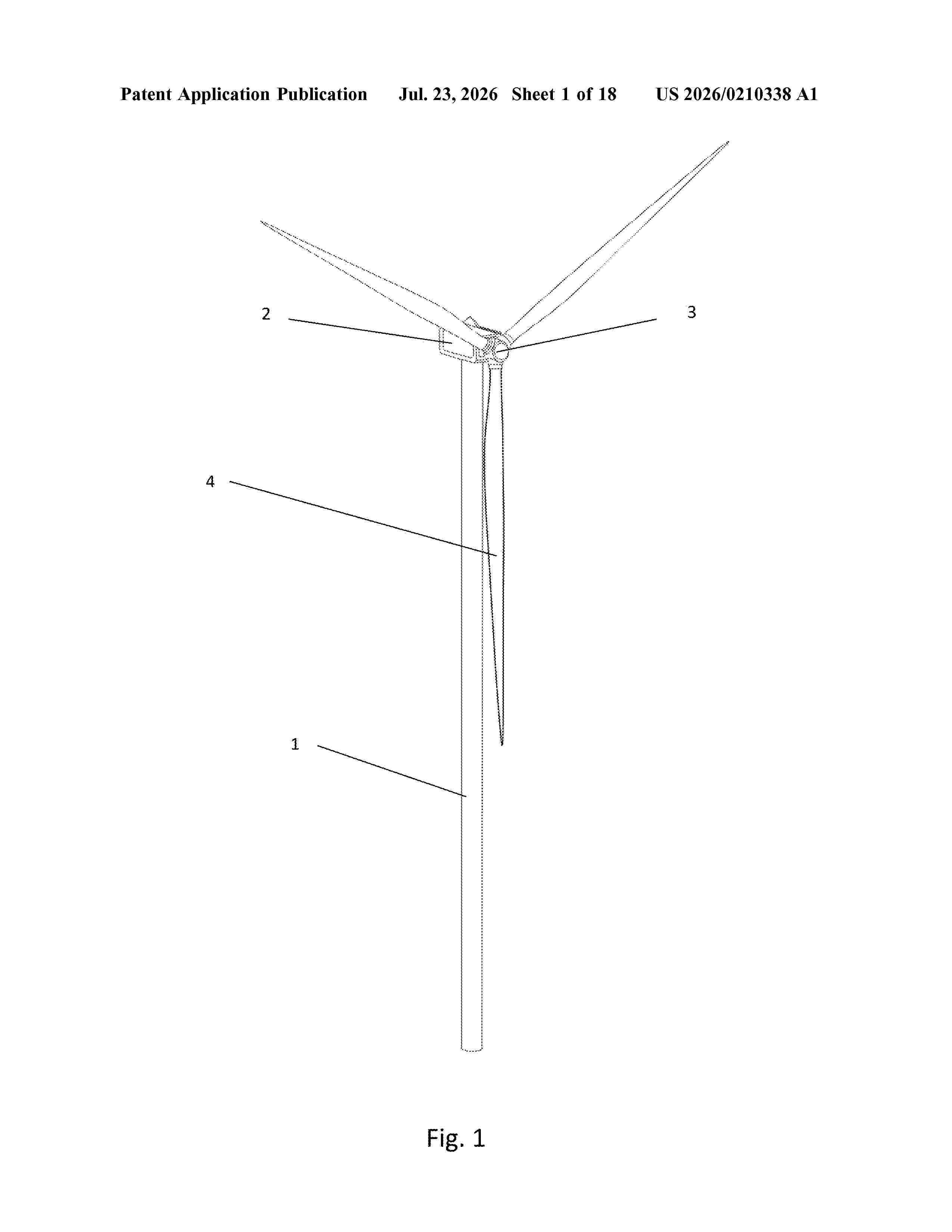
Resumen de: US20260210338A1
0000 A guiding system for exchanging a wind turbine blade, which uses an internal lifting and lowering system fixed to a rotor. The guiding system comprises semi-rigid passive retaining lines that form a safe catenary or track for lowering the blades without same hitting the tower or the ground as a result of incident winds of up to 15 m/s. A clip fastened to the end part of the blade slides along the retaining lines with the horizontal movement of the blade. The catenary may optionally have intermediate points, and the tension thereof is dependent on the incident wind: the greater the wind, the greater tension. The guiding system can be used for onshore wind turbines, floating offshore wind turbines connected to a spring, and boat-assisted offshore wind turbines on the high seas.
 BOPI
BOPI
 Sede Electrónica