Si deseas distinguir tus productos, servicios o ambos de los de otra empresa, es posible que necesites una marca o nombre comercial. Descubre qué son, en qué consiste su procedimiento de registro y qué implica.

Información sobre los plazos de presentación de solicitudes de transformación de marcas de la Unión Europea en marca nacional española. Más información


Si tienes un nuevo dispositivo, producto o procedimiento que resuelva un problema técnico o tenga una ventaja práctica, existen distintas formas de protegerlo en España y en otros países. Descubre cómo hacerlo.

¿Tu innovación reside en la estética, la ornamentación o la apariencia de tu producto? Protégela mediante un diseño industrial. Descubre qué derechos confiere el registro y cómo realizar la tramitación.

Las indicaciones geográficas protegen el nombre de un producto originario de una zona geográfica, a la cual le debe una determinada calidad, reputación u otra característica. Descubre qué son, en qué consiste su procedimiento de registro y qué beneficios conceden.

Las patentes publicadas en todo el mundo son una valiosa fuente de información científica, técnica y comercial.

Si eres emprendedor/a o una empresa y quieres potenciar y mejorar la rentabilidad de tu negocio protegiendo de forma adecuada los activos intangibles de tu organización, en este espacio encontrarás lo necesario.


 463
resultados
463
resultados
 Última actualización
25/04/2026 [07:54:00]
Última actualización
25/04/2026 [07:54:00]


 Resultados 225 a 250 de 463

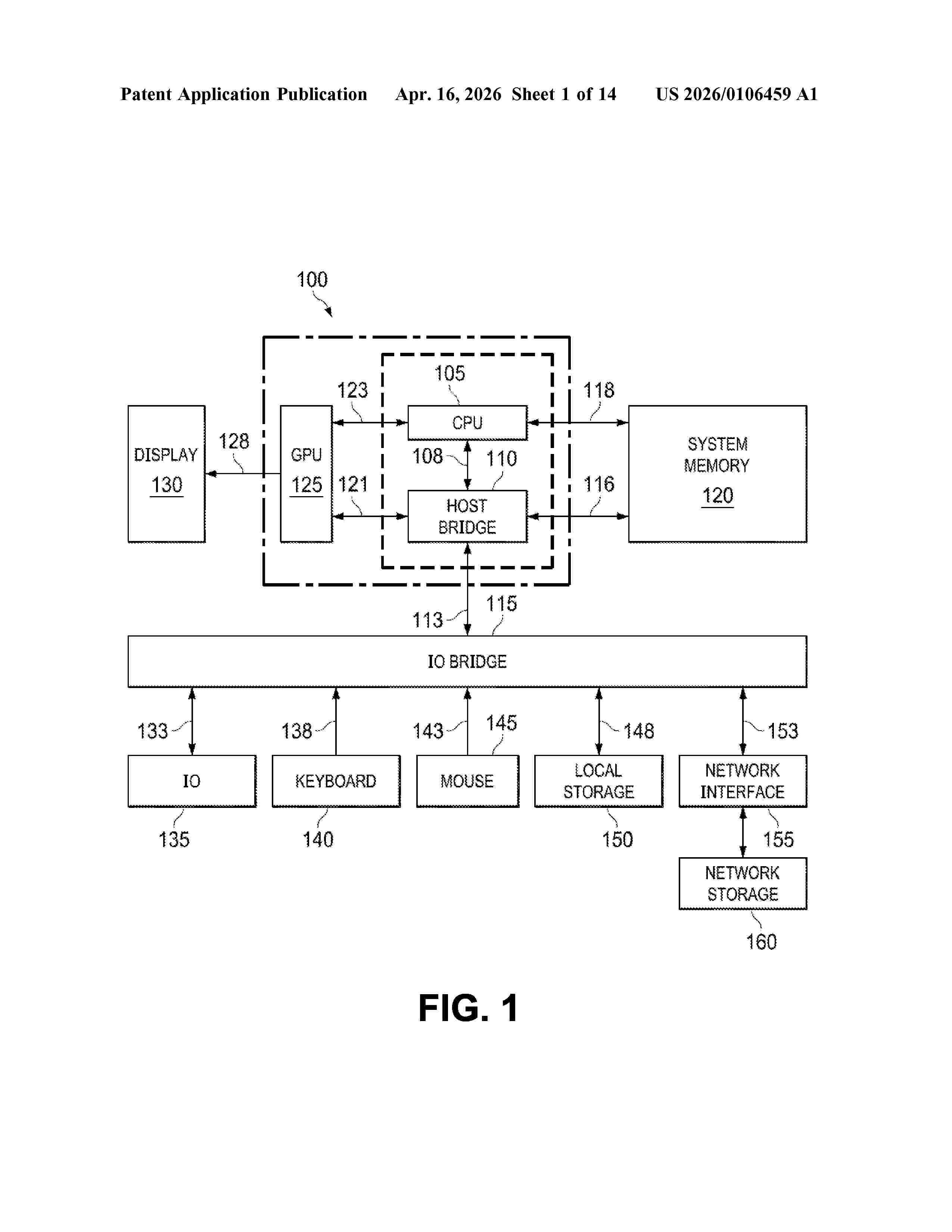
Resumen de: US20260106459A1
A system includes a flexible datacenter and a power generation unit that generates power on an intermittent basis. The flexible datacenter is coupled to both the power generation unit and grid power through a local station. By various methods, a control system may detect a transition of the power generation unit into a stand-down mode and selectively direct grid power delivery to always-on systems in the flexible datacenter.

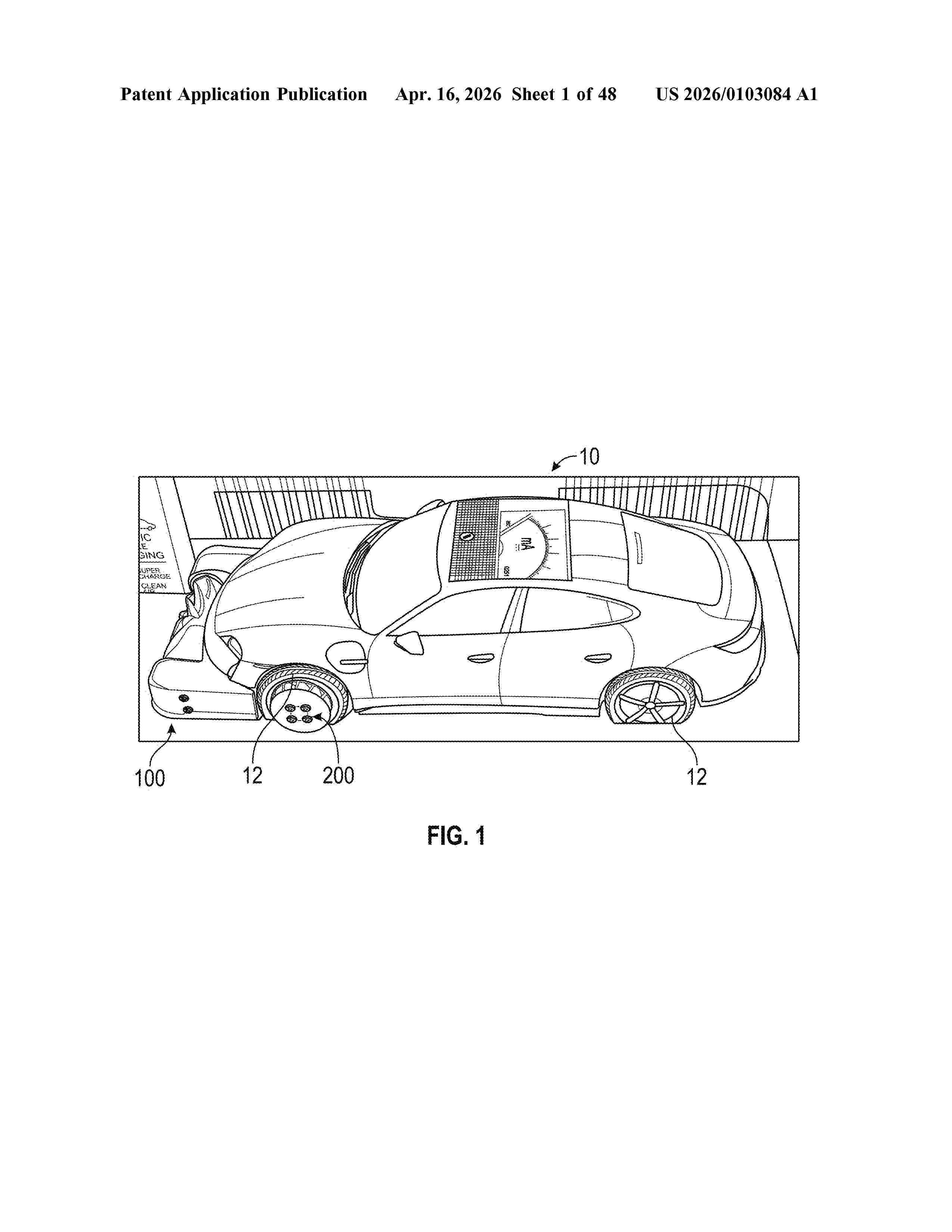
Resumen de: US20260103084A1
A system for harvesting kinetic wind energy for a vehicle includes a turbine drivingly connected to a motor/generator. The turbine is configured to be driven by the force of air encountered during operation of the vehicle and/or from wind when parked, and to drive the motor/generator to generate electrical power.
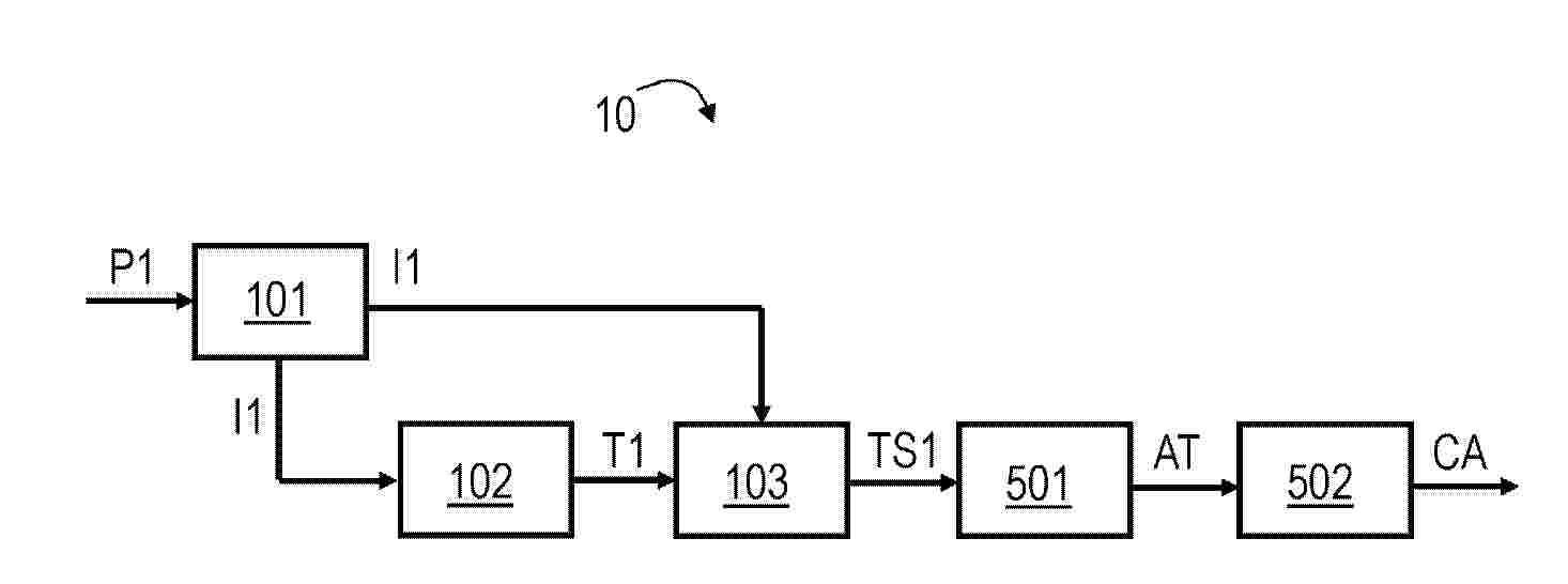
Resumen de: EP4726204A1
A method for operating a wind turbine (1) for reducing a risk of wind turbine overloading in the presence of a wind gust event is provided, the method comprising the steps:- providing first information (II) which is representative of a rate of change of a first wind turbine parameter (P1) comprising at least one of a first wind turbine loading parameter and a first wind turbine operating parameter over time, wherein each of the first wind turbine loading parameter and the first wind turbine operating parameter depends on a wind speed at the location of the wind turbine (1),- determining an adjustable first threshold (T1) considering the first information (I1),- comparing, in a first comparison step, the first information (II) to the first threshold (T1) and generating a first trigger signal (TS1) in case the first information (II) exceeds the first threshold (T1),- generating a control action (CA) intended to reduce the risk of wind turbine overloading caused by the wind gust event in case an action trigger (AT) is generated, wherein the generation of the action trigger (AT) requires that at least the first trigger signal (TS1) is generated.Furthermore, a wind turbine (1) with a control system (10) is provided.
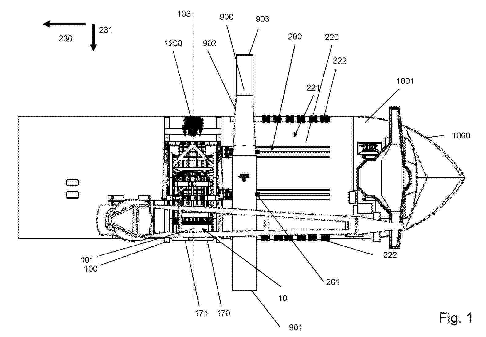
Resumen de: EP4725826A1
Handling system for transferring an elongate object from a storage location into an upending system, in particular on a vessel deck, the handling system comprising an upending system configured to upend said elongate object from a substantially horizontal position into a substantially vertical position; a skidding system configured to lift and skid said elongate object from a storage location into said upending system; wherein said upending system comprises a gripper unit configured to receive and grip a first end of the elongate object, the gripper unit including at least first ring element configured to engage an outer surface of the elongate object; and a support structure including two substantially parallelogram-shaped frames configured to support said gripper unit; wherein the gripper unit is tiltable between a first position in which a plane including the at least first ring element is substantially vertical and a second position in which said plane is substantially horizontal.
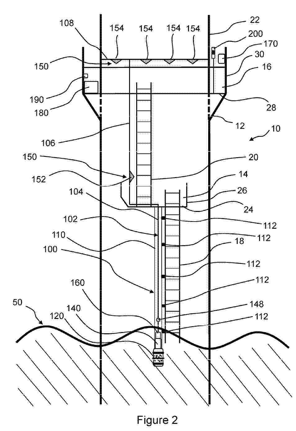
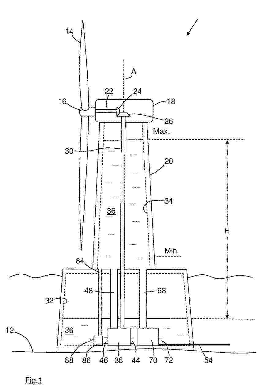
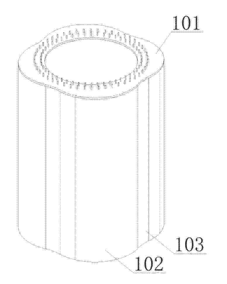
Resumen de: EP4725615A1
0001 A water delivery apparatus 100 for an offshore structure 10 comprises a hose 102 comprising a water inlet 120 towards a first end of the hose 102; a pump 140 located along the hose 102 and configured to be switched between an on state and an off state; a plurality of nozzles 150 distributed along the hose 102 for delivering high pressure water; and a controller 180 configured to switch the water delivery apparatus 100 between a standby mode and a ready mode. When the water delivery apparatus 100 is in the ready mode, the controller 180 is controllable to control the pump 140 to switch between the on state and the off state. When the water delivery apparatus 100 is in standby mode, the controller 180 is controllable to control the pump 140 to switch to the off state. Wherein in the on state, the pump 140 is configured to draw water through the water inlet 120 to deliver said water to the plurality of nozzles 150 and wherein the plurality of nozzles 150 are positioned such that the delivered water cleans at least part of said offshore structure 10.
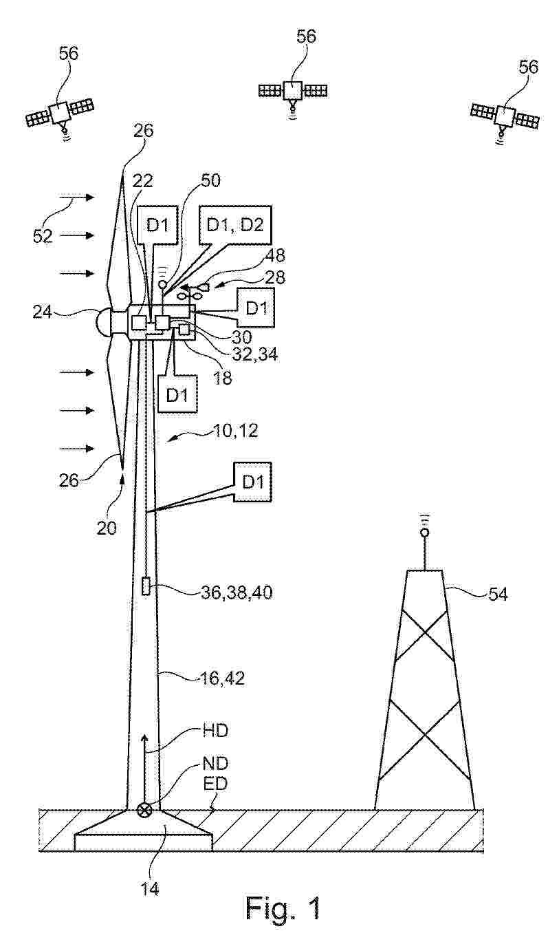
Resumen de: EP4726205A1
The invention relates to a method for determining a spatial position of a portion of an infrastructure element (10), especially a wind energy plant (12). The method comprises obtaining first data (D1) indicative of an operational parameter of the infrastructure element (10) and/or indicative of an environmental parameter of the environment in which the infrastructure element (10) is located. The method further comprises inferring second data (D2) indicative of a position of the portion of the infrastructure element (10) based on the obtained first data (D1) and based on a trained data model (66), wherein the data model (66) is trained to provide a spatial position of the portion of an infrastructure element (10) based on the first data (D1). Moreover, the invention is directed to a method for monitoring the infrastructure element (10), to a method for training the data model (66) as well as to a data processing apparatus (30), a computer program and a computer readable storage medium for executing said methods. Furthermore, a system (28) for monitoring an infrastructure element (10) and an infrastructure element (10) are described.
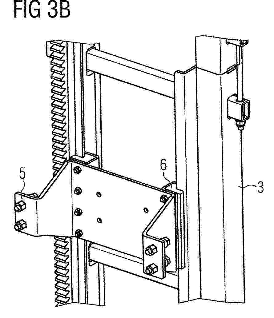
Resumen de: EP4726206A1
0001 The present invention relates to a method for installing a rack and pinion lift system in a wind turbine tower. The method comprises the following steps: Providing a first tower section of a wind turbine, fixing a first lift mast at an inner wall of the first tower section, providing a second tower section of a wind turbine, fixing a second lift mast at an inner wall of the second tower section, and stacking the first and second tower sections upon each other and connecting the first and second lift masts, thereby forming a continuous rack. 0002 The present invention further describes a rack and pinion lift system that is obtainable by this installation method. 0003 Moreover, the present invention relates to a tower section for a wind turbine tower. The tower section comprises a lift mast that is fixed at an inner wall of the tower section via a lift mast support structure. The lift mast support structure is configured to allow for a vertical movement of the lift mast vis-à-vis the inner wall of the tower section.
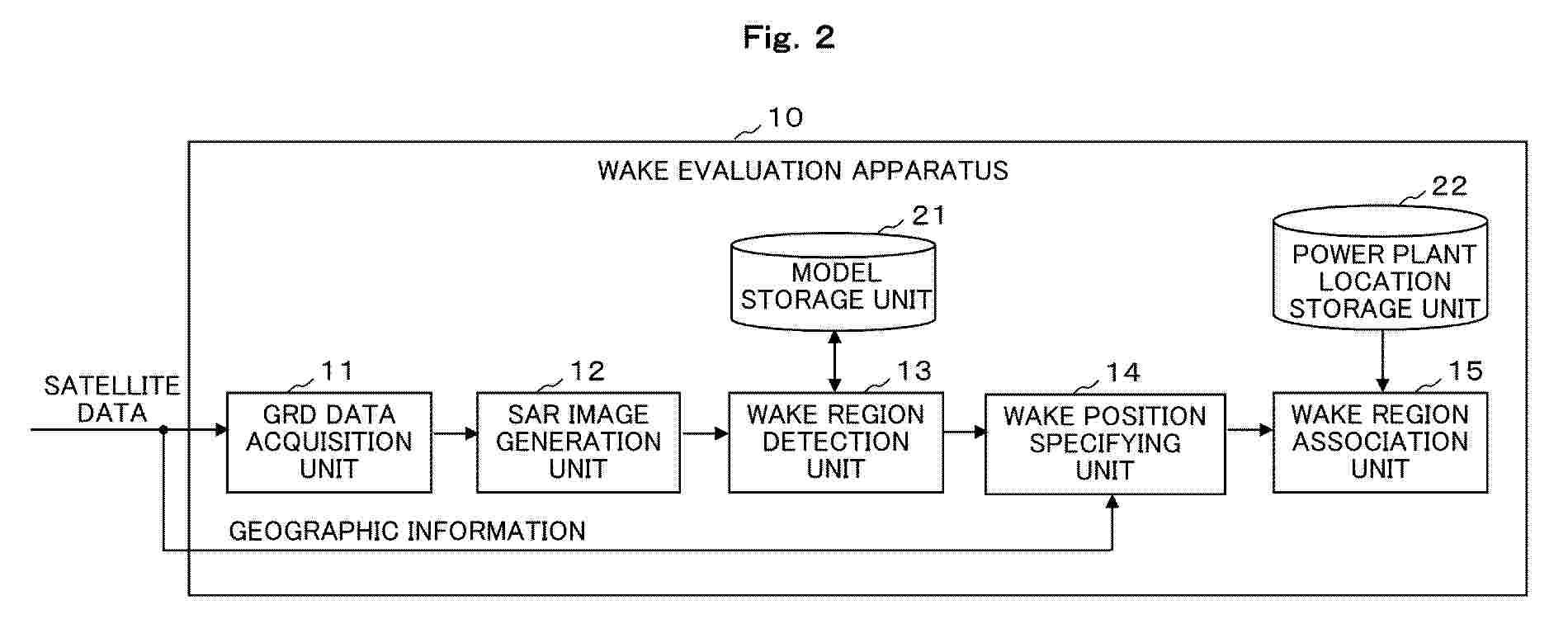
Resumen de: EP4726208A1
0001 A wake evaluation apparatus includes: a wake region detection unit 13 that analyzes an SAR image observed using a satellite's synthetic aperture radar using a machine learning model and detects one or more wake regions included in the SAR image; a wake position specifying unit 14 that specifies the position information of the wake region detected by the wake region detection unit 13 based on geographic information of the observation area measured by the satellite; and a wake region association unit 15 that associates the wake region with a wind power plant at a corresponding location based on the specified position information of the wake region and position information of the wind power plant specified in advance, and is configured to be able to evaluate wakes generated around a wind power plant without providing a transect by using a novel analysis method that is executed by applying the SAR image to the machine learning model.
Resumen de: EP4556293A1
This patent application presents a groundbreaking self-charging wind-powered vehicle system designed for a wide range of transportation modes, including cars, lorries, trains, trams, and airplanes. The core innovation involves the integration of advanced wind turbines into these vehicles, enabling the capture of kinetic energy from the environment and its conversion into electrical power. This sustainable energy source offers a compelling solution to reduce carbon emissions, minimize reliance on fossil fuels, and deliver cost-effective and environmentally friendly transportation.Traditional transportation systems primarily rely on fossil fuels, resulting in environmental pollution and the depletion of finite resources. In contrast, the proposed self-charging wind-powered vehicle system addresses these challenges by harnessing the power of the wind efficiently.
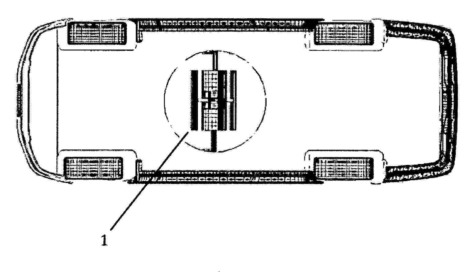
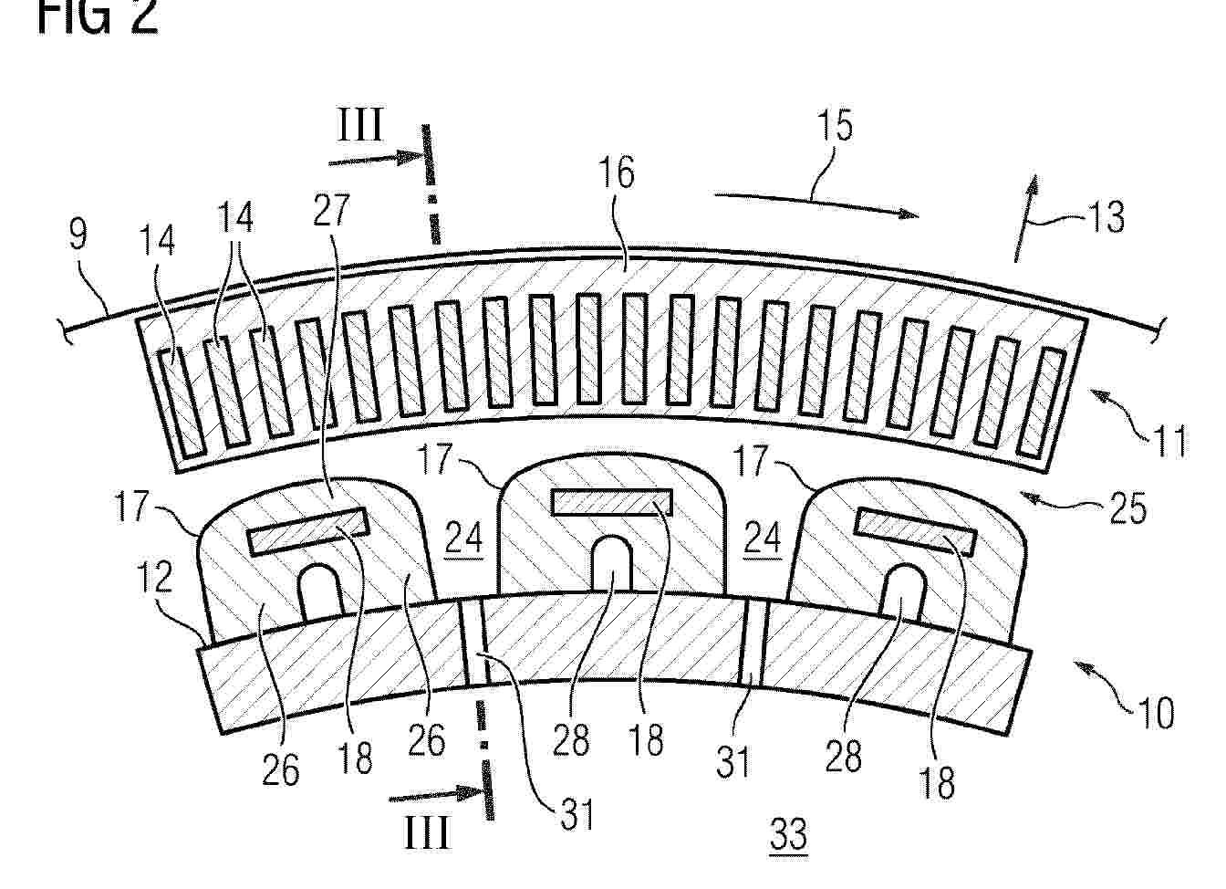
Resumen de: EP4475395A1
Electric generator for a wind turbine (1), comprising an outer stator (11) and an inner rotor (10) with a plurality of permanent magnets (18), wherein the rotor (10) is rotatably mounted about a rotation axis (6), wherein the rotor (10) is realized by a modular assembly of several modules (17) each comprising at least one of the permanent magnets (18), wherein at least one of the modules (17) delimits at least one air cooling channel (24) of the rotor (10).
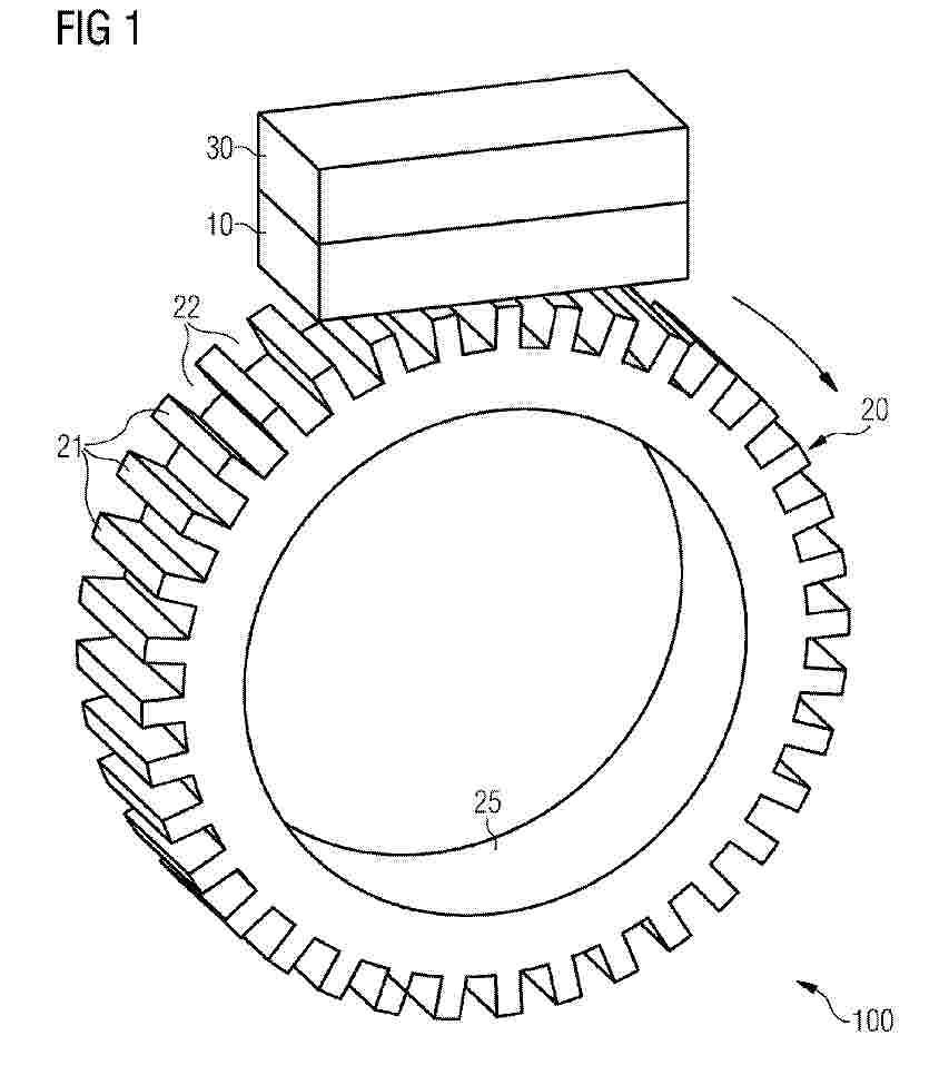
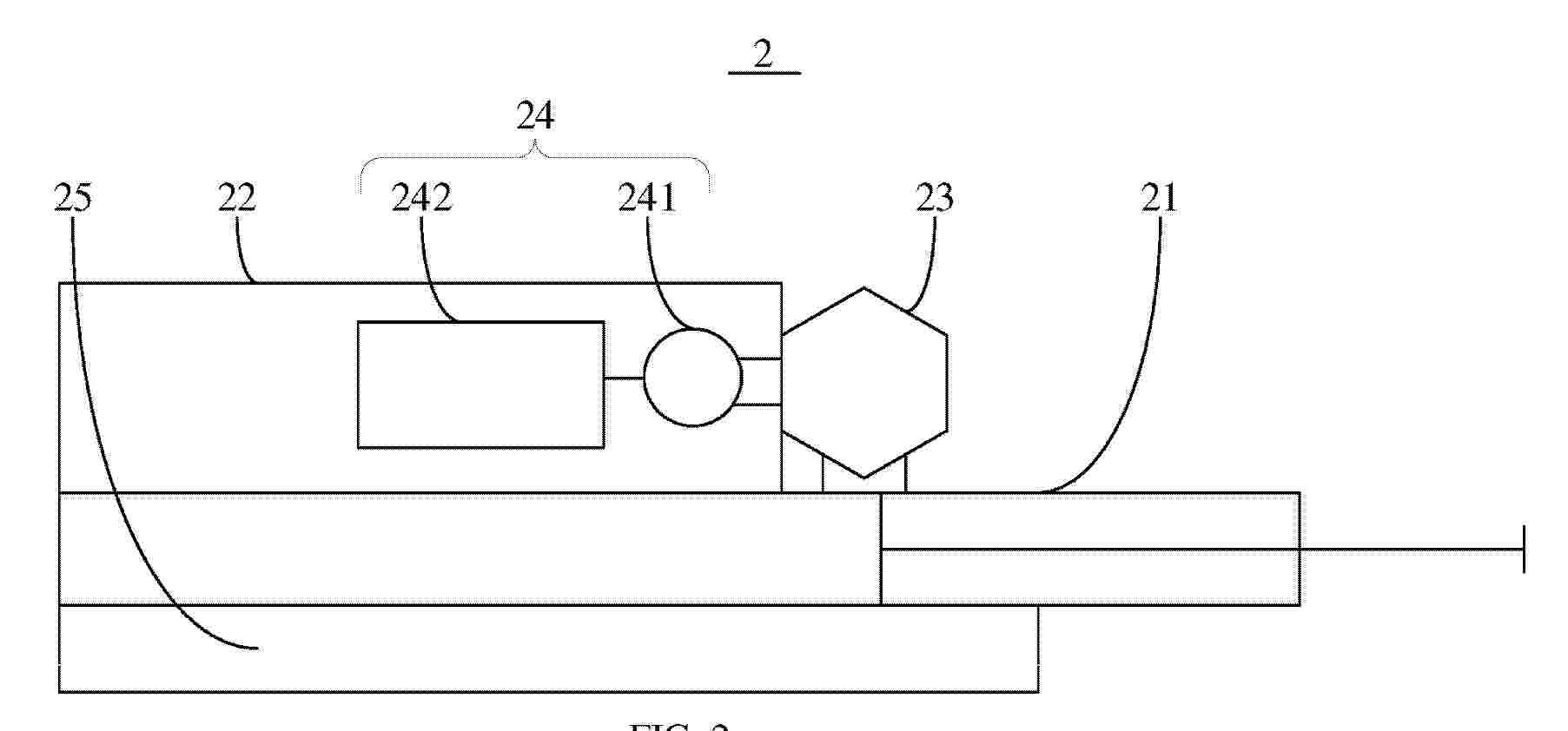
Resumen de: EP4475149A1
0001 A demagnetization system for demagnetizing a magnet element (10) of a wind turbine generator component is provided. The magnet element (10) comprises at least one permanent magnet block (15). The demagnetization system (100) comprises a reluctance modulating component (20) and a moving arrangement (70) configured to provide a relative movement between the reluctance modulating component (20) and the magnet element (10). The reluctance modulating component (20) is configured to change a magnetic reluctance experienced by a magnetic flux of the one or more permanent magnet blocks (15) as the reluctance modulating component (20) moves past the magnet element (10). The system is configured to generate eddy currents in the at least one permanent magnet block (15) by providing said relative movement between the reluctance modulating component (20) and the magnet element (10), wherein the eddy currents heat the at least one permanent magnet block (15) to be demagnetized.
Resumen de: EP4726202A1
The present invention discloses a hydraulic pitch system and a wind turbine, relating to the technical field of wind power pitch control. The hydraulic pitch system includes a hub and a hydraulic apparatus. The hydraulic apparatus is arranged in the hub. The hydraulic apparatus includes a cylinder for driving a blade movement and an oil tank for storing hydraulic oil. The cylinder is connected to the oil tank via a connecting pipeline. The connecting pipeline is provided with a valve assembly and a hydraulic drive apparatus for controlling a flow of hydraulic oil in the connecting pipeline. The valve assembly and the hydraulic drive apparatus are both mounted on the cylinder. By arranging the hydraulic apparatus in the hub, on the one hand, a hydraulic-electric slip ring can be omitted, which not only avoids a failure of the hydraulic-electric slip ring but also reduces the cost of the hydraulic pitch system; on the other hand, pipelines in a nacelle can be omitted, which helps reduce leakage points in the pipelines. At the same time, it is also convenient for the valve assembly to be integrated on the cylinder, which helps further reduce a length of pipelines, thereby solving problems of high cost of the hydraulic pitch system and a risk of oil leakage.
Resumen de: GB2644476A
The invention relates to a wind turbine for the generation of electricity. The wind turbine has a number of blades carried by a hub which is rotatably mounted to a tower. The wind turbine has a first reservoir and a second reservoir for a working liquid, the working liquid in the second reservoir being above the working liquid in the first reservoir. The wind turbine also has a turbine with an inlet in communication with the second reservoir and an outlet in communication with the first reservoir, an output shaft of the turbine being connected to the rotor of an electrical generator. The hub is connected by way of a drive shaft to at least one positive displacement pump. The pump has an inlet and an outlet, the inlet being in communication with the first reservoir. The outlet of the pump has a two-way valve which is changeable between a first condition in which the outlet is in communication with the first reservoir and a second condition in which the outlet is in communication with the second reservoir. The outlet of the pump can be switched between a second condition in which working fluid is pumped into the second reservoir and a first condition in which the working fluid is pumped back into the first reservoir. There can be a plurality of pumps which are independently switchable between their first and second conditions whereby to enable the power consumed by the pumps to be adjusted substantially to balance the power being extracted from the wind. The displacement of the
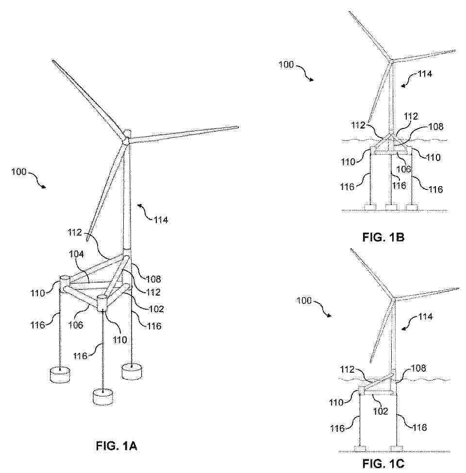
Resumen de: GB2644468A
A buoyant offshore renewable energy system mounting platform is provided for use in supporting a renewable energy system in a body of water. The platform (100) comprises: a support node (108); two distal nodes (110); and a first lateral brace and a second lateral brace (102, 104), each of the first and second lateral braces extending between the support node and a corresponding distal node to form a platform base; the platform further comprising a plurality of mooring lines (116), wherein a corresponding said mooring line is affixed to each of the support node and the two distal nodes and arranged to tether the support node and the two distal nodes to a bed of a body of water such that the support node and the two distal nodes are positioned in the body of water at an operating depth; wherein the support node is arranged to support a renewable energy converter (114) thereon, and wherein at the operating depth, the support node is arranged to support the renewable energy converter above a surface of the body of water. The described platform aims to provide a safer and more efficient mode of deploying a buoyant offshore platform to a partially submerged operating configuration.
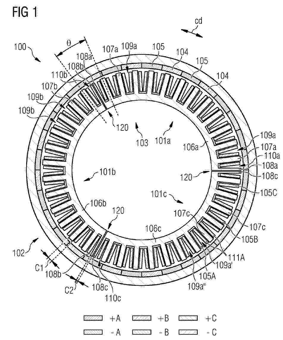
Resumen de: EP4701045A1
0001 It is described a Stator segment (101a,b,c) for an electrical machine (100), in particular permanent magnet synchronous electrical generator, comprising: a core ring portion (106a,b,c) extending in a circumferential direction (cd) forming less than a whole circumference; plural first teeth (107a,b,c) extending radially from the ring portion (106a,b,c); two second teeth (108a,b,c) extending radially from the ring portion (106a,b,c) and being arranged at two circumferential ends of the ring portion; wherein between each of two adjacent first teeth (107a,b,c) a first slot (109a,b,c) is formed, wherein between each of the second teeth (108a,b,c) and an adjacent first tooth (107a,b,c) a second slot (110a,b,c) is formed, the stator segment further comprising: a multiple phase winding set (105A,B,C) wound according to a concentrated winding topology.
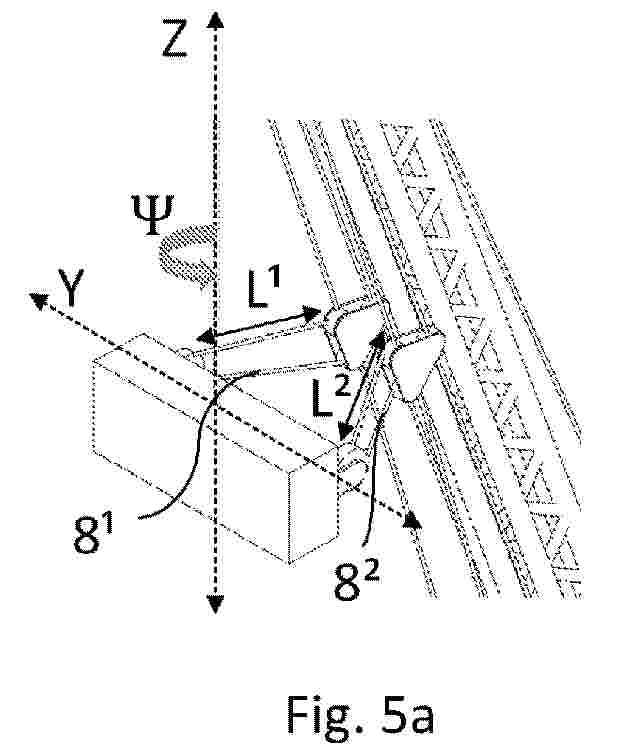
Resumen de: WO2024251337A1
The present invention relates to a crane system for handling a load (3, 4), and a method for controlling the load (3, 4) during hoisting operation. The method present acts for controlling the orientation of a load (3, 4) during hoisting operation using a speed controlling method. A winch (5) control system controls a winch (5) arrangement, wherein the winch (5) arrangement is arranged relative to a crane system. The method comprising the following steps, placing the load (3, 4) in a first load (3, 4) position, and attaching the first tagline (8) and the second tagline (8, L2) to a first and a second attachment point on the load (3, 4), determining a predicted virtual axis for a next load (3, 4) position relative to the previous virtual axis, moving the load (3, 4) to the next load (3, 4) position relative to the predicted virtual axis while controlling each of the first and second winch (9), such that each of the first and second tagline length (8) are adjusted separately relative to the predicted virtual axis, retrieving at least one first tagline length (LI) information from a first measuring device and at least one second tagline length (8) information from a second measuring device in the next load (3, 4) position, analysing the first and second tagline length (8) information relative to each other to determine an offset value for each of the first and second tagline length (8), and comparing the offset values to the predicted virtual axis related to a current load (3, 4)
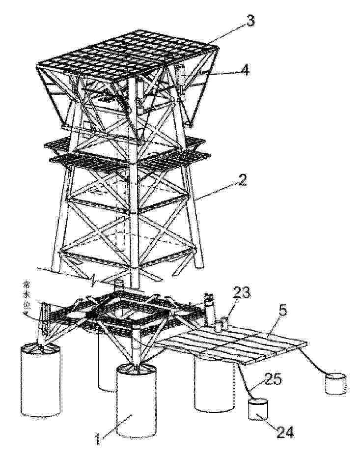
Resumen de: CN121849295A
本发明涉及一种吸力式海洋自然保护区观测值守平台,其特征在于,包括设在海上的多个吸力筒基础和安装在各吸力筒基础上的导管架主体,所述导管架主体上设有光伏发电装置和垂直轴风力发电机,临近导管架主体的海上设有波浪发电装置,光伏发电装置、垂直轴风力发电机和波浪发电装置为平台上的用电设备供电;所述导管架主体上端设有停机坪和设在停机坪两侧部的矩形状太阳能板斜框架,太阳能板斜框架的上端边与停机坪的侧边贴近,太阳能板斜框架的下端边与导管架主体连接,该吸力式海洋自然保护区观测值守平台能够将太阳能光伏板进行位置切换,从而满足停机或光伏发电的不同场景的使用需求。
Resumen de: CN121854335A
本发明公开了一种用于老旧风机扩容改造项目的转接段结构及其制造和使用方法,属于风力发电技术领域。该结构包括转接段顶板、底板、内塔筒、加劲肋以及由旧塔筒切割重组形成的第一、第二外塔筒板。通过将旧塔筒轴向三等分并分别构建内、外双层套筒,利用加劲肋连接形成整体受力体系,显著提升了塔架的轴向抗压、抗弯、抗剪及整体稳定承载力。本发明还提供了关键的设计计算方法,包括内外筒间距估算、承载力提升比例计算及焊接周期预估公式。本发明方法实现了老旧塔筒材料的高效循环利用,大幅降低了改造成本与资源消耗,为风电场“以大代小”绿色改造提供了可靠的技术解决方案。
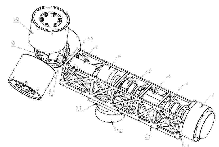
Resumen de: CN121854353A
本发明属于风力发电技术领域,尤其涉及一种风电机组试验模型机头及使用方法,试验模型机头包括:支撑机构,可拆卸安装在风电机组试验模型塔筒顶部;传动轴,设置在支撑机构内部;驱动机构,设置在支撑机构一端,驱动机构的输出端与传动轴传动连接;叶片连接机构,设置在支撑机构另一端,叶片连接机构与传动轴传动连接,叶片连接机构用于固定试验模型叶片并对叶片变桨角度进行调节;数据采集机构,设置在支撑机构上,数据采集机构用于采集试验数据。本发明能够达到全面模拟风电机组机舱功能,并实现对关键试验数据监测,极大地提升风电机组模型试验模拟的保真度的目的。
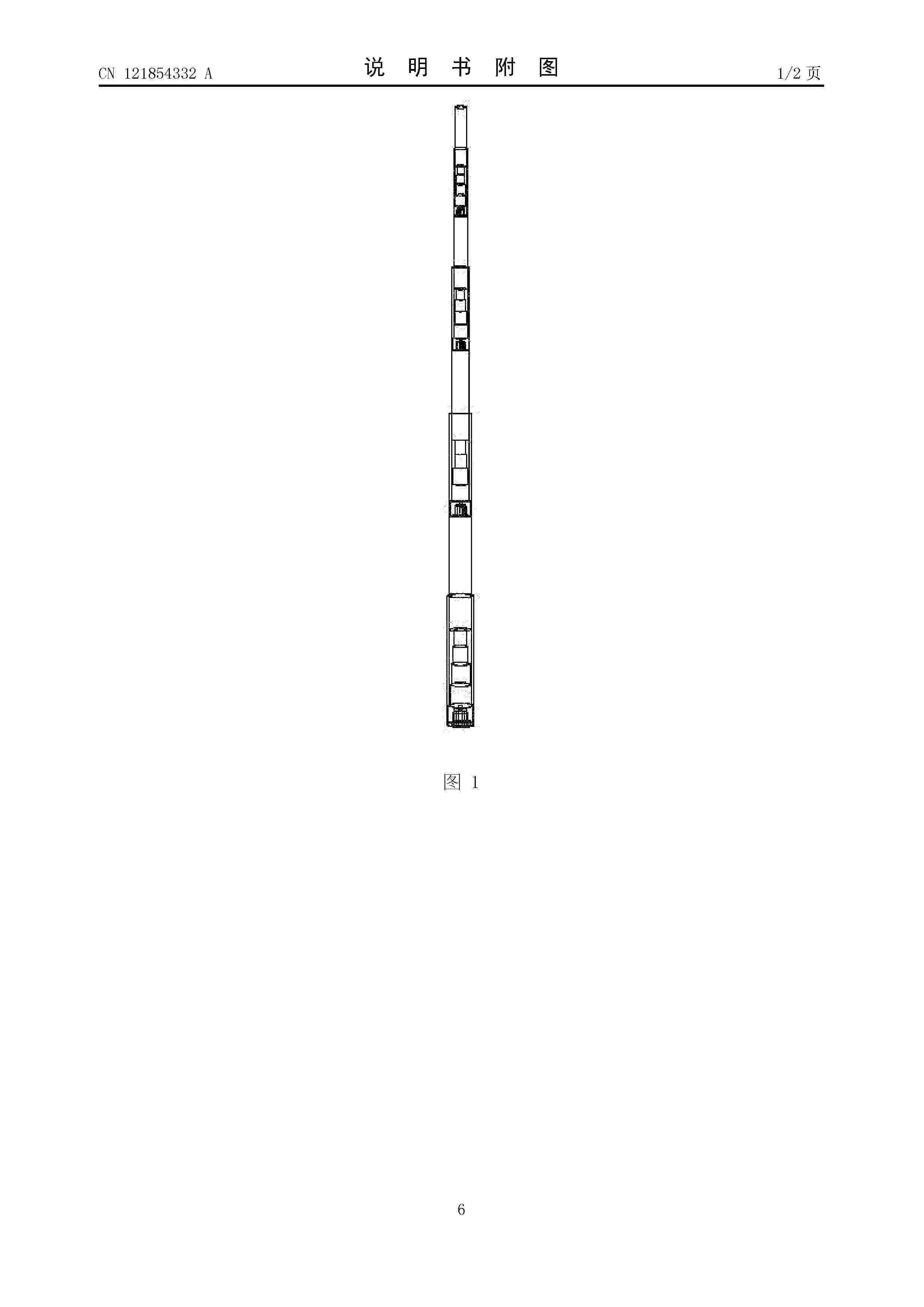
Resumen de: CN121854332A
本发明提供一种分节段上下伸缩的风力发电机杆筒,包括动力筒和延伸筒两个部分;所述延伸筒为圆柱空心管体,所述延伸筒的顶端管口和底端管口分别设置有钢板封头;所述动力筒的内径等于所述延伸筒的外径;所述延伸筒在所述动力筒的筒体内上下滑动;所述动力筒一节段和所述延伸筒一节段为一组,上下多组接高时上面一组的所述动力筒与下面一组的所述延伸筒同轴同径。本发明均采用圆柱空心管体结构,通过精密的内外径配合,实现了延伸筒在动力筒内的顺畅滑动。这种分节段的设计使得风力发电机杆筒能够进行高度的调整,从而适应不同风况下的发电效率以及规避大风天气的需求;这一创新技术对于推动风力发电技术的发展具有重要意义。
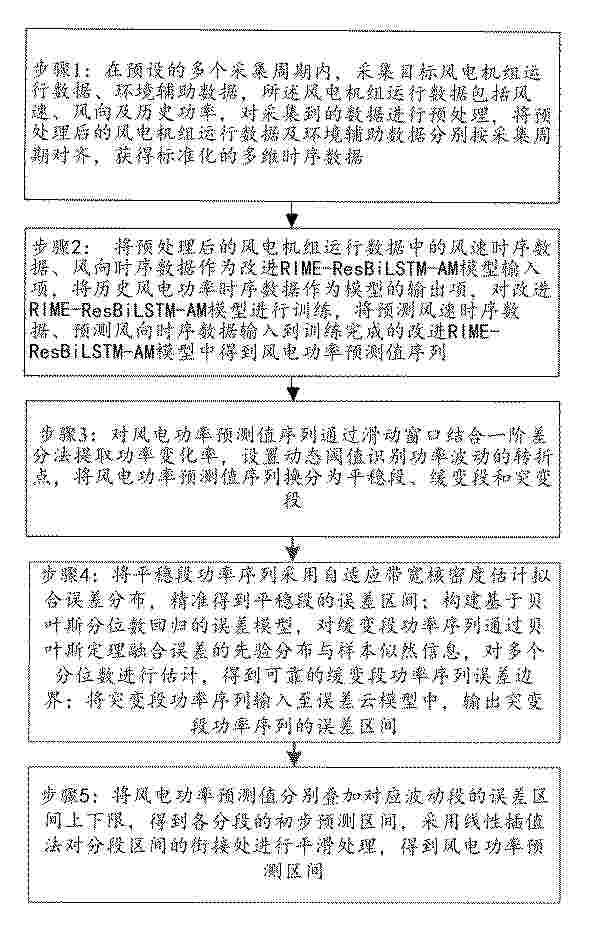
Resumen de: CN121863344A
本发明提供一种基于改进RIME‑ResBiLSTM‑AM模型的风电功率点‑区间预测智能自适应调控方法及系统,涉及风电功率预测技术领域。具体步骤包括:多个采集周期内,采集风电机组运行数据与环境辅助数据,经预处理及周期对齐,生成标准化多维时序数据。以预处理后的风速、风向时序数据为输入、历史风电功率为输出,训练改进RIME‑ResBiLSTM‑AM模型,输入预测风速、风向数据,得到风电功率预测值序列。提取功率变化率并设动态阈值,将序列划分为平稳、缓变、突变三段,分别通过自适应带宽核密度估计、贝叶斯分位数回归、误差云模型获取误差区间。预测值叠加对应误差区间上下限,经线性插值平滑衔接,即得风电功率预测区间。
Resumen de: CN121854333A
本发明涉及海上风电工程技术领域,公开了一种海上风电运维靠泊防撞结构。防撞结构包括导管架和缓冲机构;缓冲机构设置在导管架上,缓冲机构包括安装支架、滚动接触元件、以及弹性复位组件。在自然状态下,滚动接触元件部分凸出于导管架的临水侧之前。工作时,滚动接触元件首先接触靠泊船体,弹性复位组件通过压缩形变吸收冲击能量;冲击结束后,其释放弹性势能驱动安装支架复位,使船体与导管架之间形成保持间隙,从而将船体因海浪浮动产生的持续滑动摩擦转化为与滚动接触元件之间的低磨损滚动摩擦。本发明能够有效缓冲靠泊冲击,并解决长期摩擦磨损难题,提升了防护耐久性与基础安全性。
Resumen de: CN121853841A
本发明涉及新能源收集技术领域,并具体公开了一种集成新能源收集存储、无人机运维与电车充电的通信信号塔,包括信号塔基座,所述信号塔基座的侧面底部固定连接有汽车充电平台,所述信号塔基座的侧面位于汽车充电平台上方的位置固定连接有无人机平台,所述偏转组件包括第二伸缩杆,所述第二伸缩杆的驱动轴固定连接有转动座,所述转动座的侧面转动连接有偏转扇叶,所述偏转扇叶的侧面转动连接有调整拉杆的一端,所述调整拉杆远离偏转扇叶的一端与第二伸缩杆的固定端侧面转动连接,该集成新能源收集存储、无人机运维与电车充电的通信信号塔,达到了便于进行光伏收集利用和无人机维护的目的。
Resumen de: CN121854352A
本发明公开了风力发电机动轴高强螺栓断丝脱落无线检测装置及方法,属于风力发电设备状态监测技术领域。包括有若干螺栓、若干漆包线、开关量无线发送模块、开关量无线接收模块、PLC输入模块,螺栓用于连接风力发电机组动轴系统的各部件,漆包线的一端和螺栓的非导电部位固定,漆包线的另一端和开关量无线发送模块的输入接口电性连接,开关量无线发送模块固定在风力发电机组的动轴系统的旋转部件上,开关量无线发送模块和开关量无线接收模块无线通讯连接,开关量无线接收模块固定在风力发电机组的固定部件上,开关量无线接收模块和PLC输入模块电性连接,PLC输入模块为风力发电机组的预制模块。
Nº publicación: CN121854343A 14/04/2026
Solicitante:
华电(云南)新能源发电有限公司华电电力科学研究院有限公司武汉智原科技有限责任公司
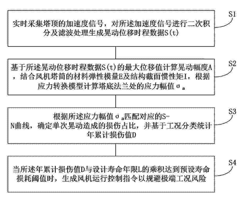
Resumen de: CN121854343A
本发明公开一种风机塔筒寿命监测方法及存储介质,方法包括:通过加速度信号生成位移时程数据,结合动态修正的应力幅值计算模型,匹配S‑N曲线确定单次损伤占比,按工况分类统计年累计损伤值,并基于剩余寿命指数触发分级风险控制。本发明解决了传统方法中环境适应性差、损伤量化不准、风险响应滞后问题,显著提升塔筒全生命周期安全性。
 BOPI
BOPI
 Sede Electrónica