Si deseas distinguir tus productos, servicios o ambos de los de otra empresa, es posible que necesites una marca o nombre comercial. Descubre qué son, en qué consiste su procedimiento de registro y qué implica.

Información sobre los plazos de presentación de solicitudes de transformación de marcas de la Unión Europea en marca nacional española. Más información


Si tienes un nuevo dispositivo, producto o procedimiento que resuelva un problema técnico o tenga una ventaja práctica, existen distintas formas de protegerlo en España y en otros países. Descubre cómo hacerlo.

¿Tu innovación reside en la estética, la ornamentación o la apariencia de tu producto? Protégela mediante un diseño industrial. Descubre qué derechos confiere el registro y cómo realizar la tramitación.

Las indicaciones geográficas protegen el nombre de un producto originario de una zona geográfica, a la cual le debe una determinada calidad, reputación u otra característica. Descubre qué son, en qué consiste su procedimiento de registro y qué beneficios conceden.

Las patentes publicadas en todo el mundo son una valiosa fuente de información científica, técnica y comercial.

Si eres emprendedor/a o una empresa y quieres potenciar y mejorar la rentabilidad de tu negocio protegiendo de forma adecuada los activos intangibles de tu organización, en este espacio encontrarás lo necesario.


 1357
resultados
1357
resultados
 Última actualización
05/05/2026 [07:31:00]
Última actualización
05/05/2026 [07:31:00]


 Resultados 25 a 50 de 1357

Resumen de: US20260121106A1
0000 Method for producing a solid-state secondary battery electrode, using PTFE, capable of reducing resistance of the electrode and achieving strength of a positive electrode mixture sheet, and a binder. Method for producing a solid-state secondary battery sheet, including (1) preparing a composition for producing a secondary battery sheet by using a binder that is a powder which comprises a polytetrafluoroethylene resin and a conductive aid homogeneously mixed and which is free of an active material, and (2) applying a shear force while mixing the composition for producing a secondary battery sheet to obtain an electrode mixture, wherein step (2) is carried out with a content of a solvent in the composition for producing a secondary battery sheet being 10% by mass or less.

Resumen de: US20260121057A1
0000 Provided is a method for producing a secondary battery electrode, using PTFE, capable of reducing electrical resistance thereof and achieving excellent strength at the same time, and a binder. A method for producing a secondary battery electrode using a non-aqueous electrolytic solution, including step (1) of preparing a powder composition for producing an electrode by using a binder that is a powder which is composed of a composition essentially including a polytetrafluoroethylene resin and a conductive aid and which is free of an active material, and step (2) of applying a shear force while mixing the composition for producing an electrode to obtain an electrode mixture, wherein step (2) is carried out with a content of a solvent in the composition for producing an electrode being 10% by mass or less.
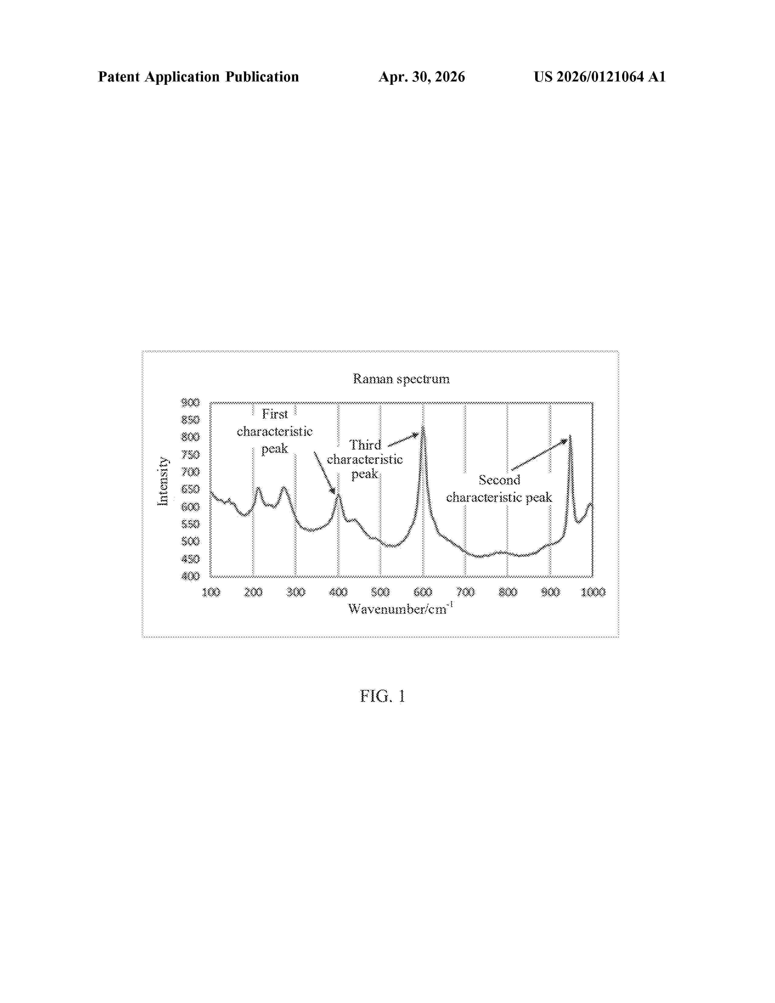
Resumen de: US20260121064A1
An electrochemical device includes a positive electrode, a negative electrode, and an electrolyte; where the positive electrode includes a positive electrode active material layer, the positive electrode active material layer includes a positive electrode active material, and the positive electrode active material includes a first positive electrode active material and a second positive electrode active material; after the electrochemical device is fully discharged, a Raman spectrum of the positive electrode active material layer has a first characteristic peak at a wavenumber ranging from 398 cm−1 to 408 cm−1 and a second characteristic peak at a wavenumber ranging from 940 cm−1 to 960 cm−1; and the second positive electrode active material includes element aluminum.
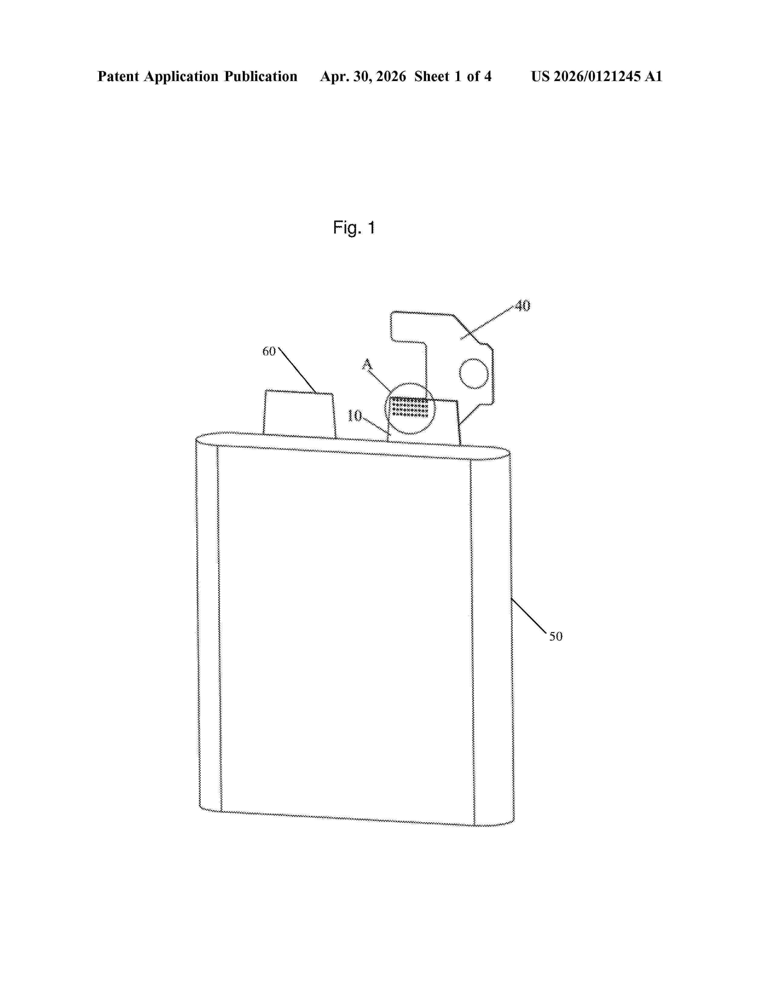
Resumen de: US20260121245A1
Disclosed are a tab welding structure and a battery. The tab welding structure includes a tab and a to-be-welded part, where the to-be-welded part is welded on the tab to form a connecting portion, a plurality of first welding mark structures that are concave in a thickness direction of the connecting portion are formed on the connecting portion, each of the plurality of first welding mark structures includes a first welding surface and a first surrounding wall that are connected to each other, and the first surrounding wall is an arc surface.
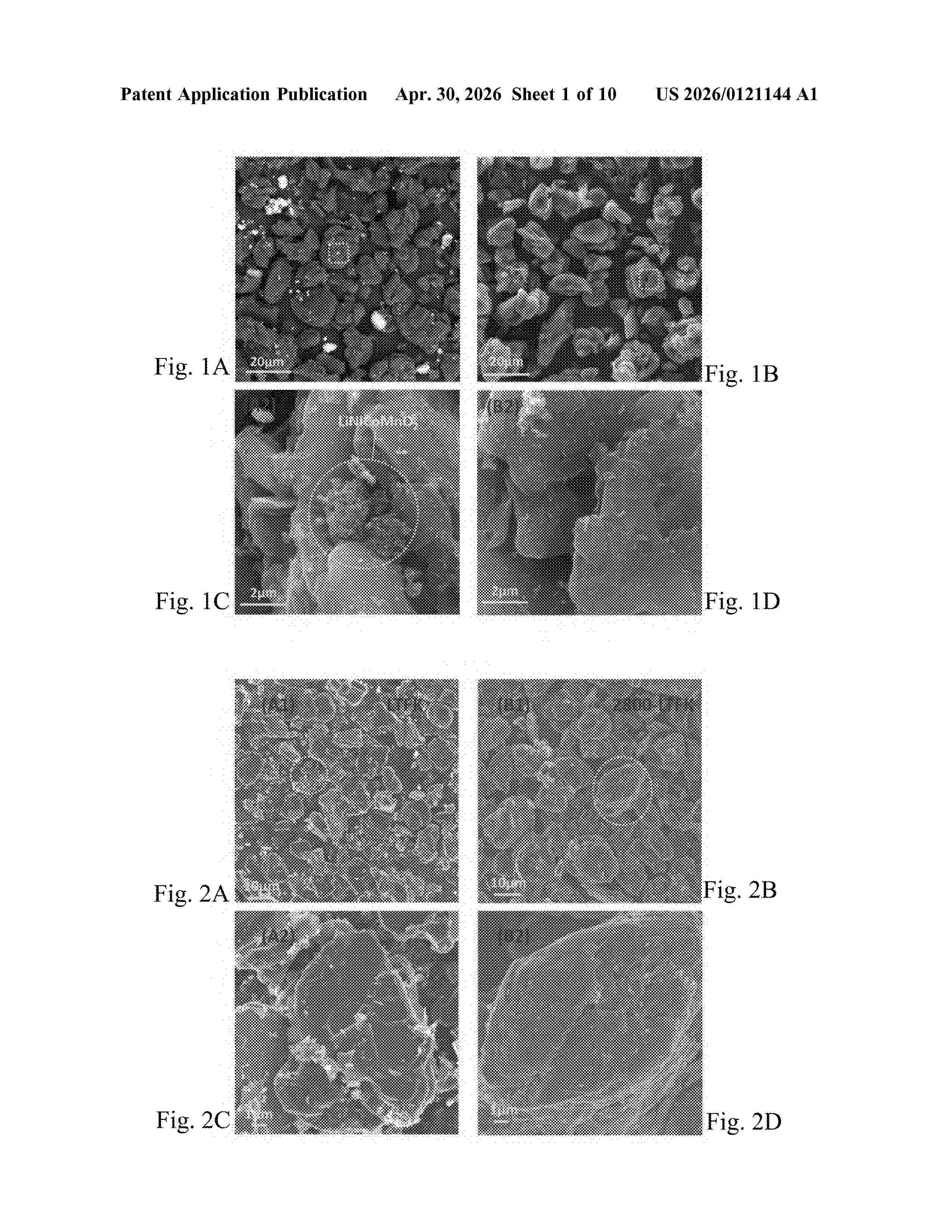
Resumen de: US20260121144A1
Preparing battery-grade graphite including: 1) placing mixed waste electrode materials of a failed lithium-ion battery in a muffle furnace, and performing low-temperature roasting surface modification in an air atmosphere yielding a powder; 2) forming a slurry of the powder, placing the slurry in a flotation machine, and after stirring the slurry, adding a collector and a foaming agent, obtaining a foam product rich in negative electrode graphite) and an ore slurry product rich in positive electrode material) by flotation separation; 3) after filtering and drying the foam product obtained in step (2), performing weak acid washing, obtaining a leached liquid and a leached residue after filtering, and obtaining negative electrode graphite after drying the leached residue; and 4) after filtering and drying the negative electrode graphite of step (3), placing the negative electrode graphite in a high-temperature graphitization furnace and performing oxygen-free heating, to obtain a regenerated graphite product.
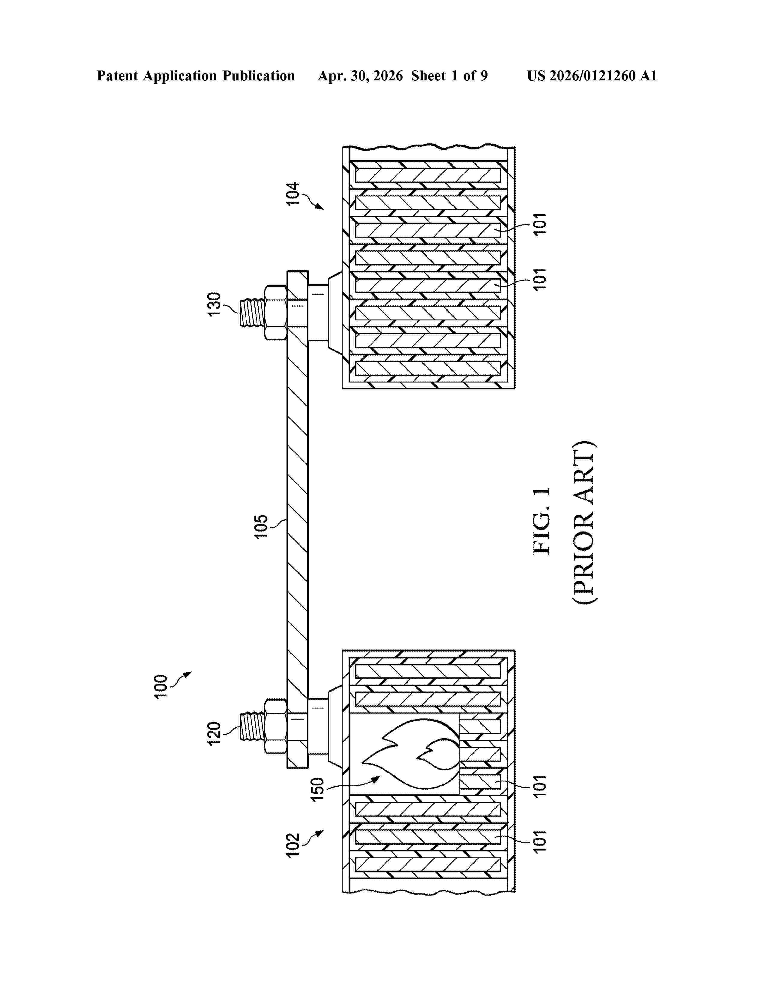
Resumen de: US20260121260A1
0000 A battery system is described with methods and systems for thermally isolating a battery module experiencing thermal runaway. In one embodiment, a thermal actuator can cut a busbar coupling neighboring battery modules together, thereby preventing or slowing the spread of thermal runaway. In other embodiments, a fusible material can joint portions of a busbar. High temperatures can cause the fusible material to melt off of the busbar portions and thereby break the thermal or electrical conductivity between busbar portions and neighboring modules.
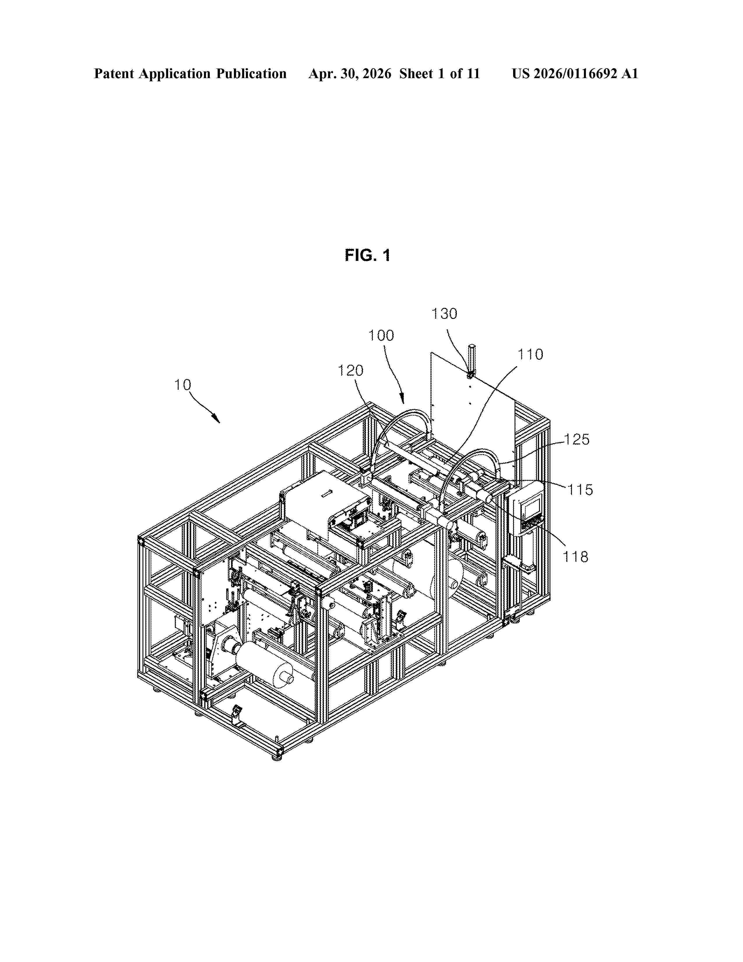
Resumen de: US20260116692A1
An apparatus for removing wrinkles from a sheet material, includes: an expander roll that rotates in a bent state with respect to a rotation axis bent to straighten and remove wrinkles formed in a sheet material being transferred to be wrinkle-removed; a roll bender that generates a bending moment to bend the expander roll; a roll rotator that rotates the expander roll; a roll controller that controls the operation of the roll bender and the roll rotator; a vision camera that photographs one surface of the sheet material being wrinkle-removed, so as to generate an input image; and a wrinkle detection module that detects wrinkles in the sheet material to be detected, using the input image.
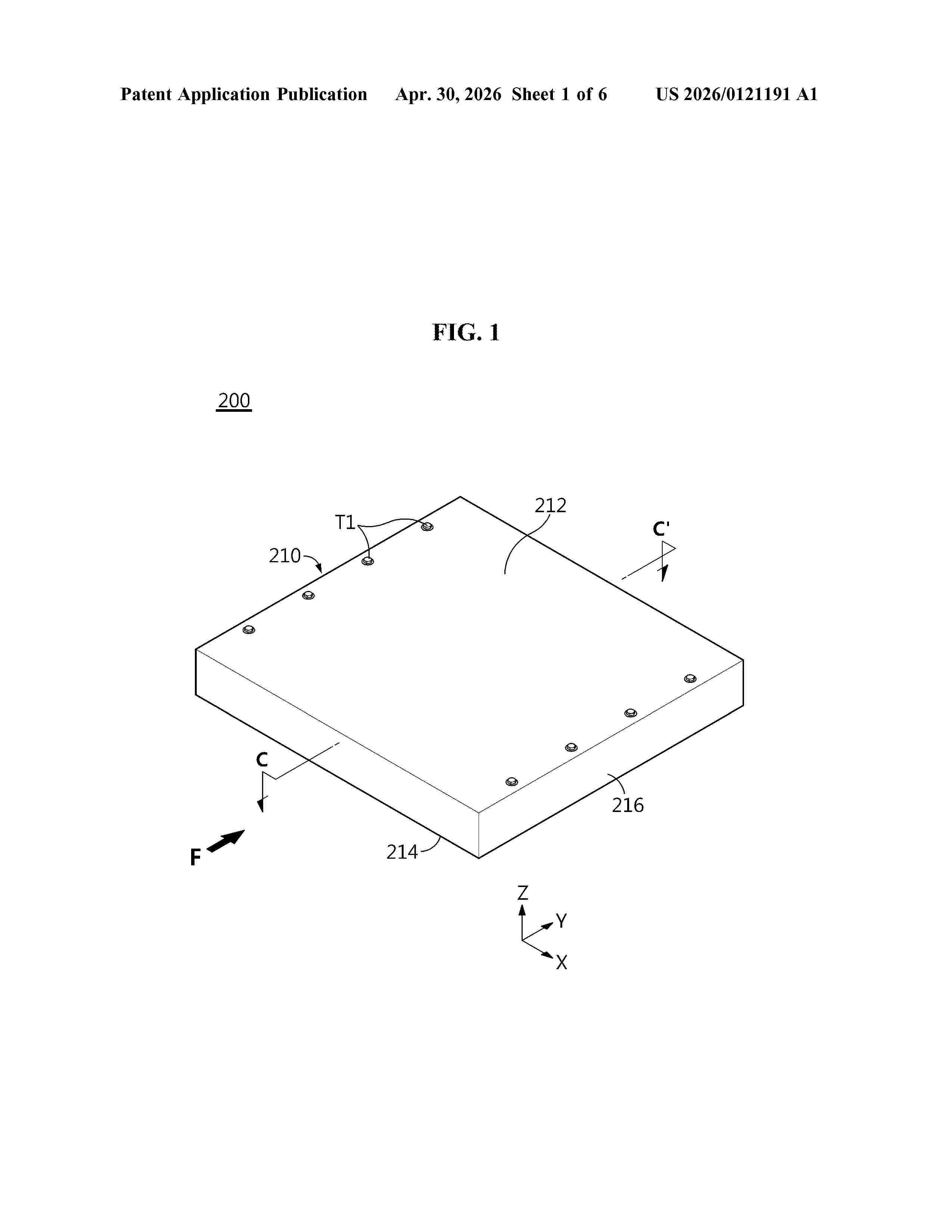
Resumen de: US20260121191A1
0000 Disclosed is a battery module having a reinforcement member to reinforce the mechanical strength of a module case. To achieve the above-described object, the battery module according to the present disclosure includes a plurality of secondary batteries arranged in at least one direction, a module case including a cover portion, a bottom portion and a side portion to form an internal space in which the plurality of secondary batteries is mounted, and a reinforcement member disposed in the module case and fixed to a lower surface of the cover portion and an upper surface of the bottom portion.
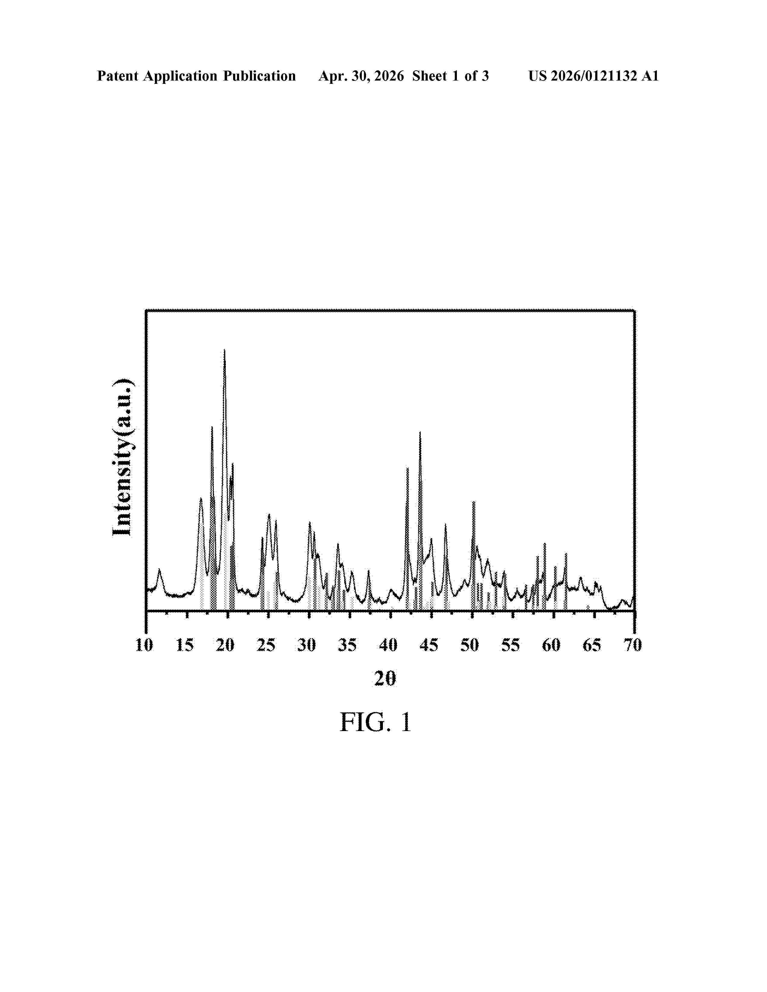
Resumen de: US20260121132A1
The present invention provides a synthesis method for a mixed zirconium salt electrolyte material and use in a lithium metal battery. The preparation method includes the following steps: first, preparing a turbid solution of a zirconium-containing mixed electrolyte material using an existing commercial lithium battery electrolyte solution as a raw material; second, centrifuging the turbid solution obtained in the first step, taking a lower-layer precipitate, and then washing away excess impurities with a commercial carbonate electrolyte solution solvent; third, drying a white precipitate obtained after washing in the second step, and then grinding and pulverizing to obtain a mixed zirconium salt electrolyte material.
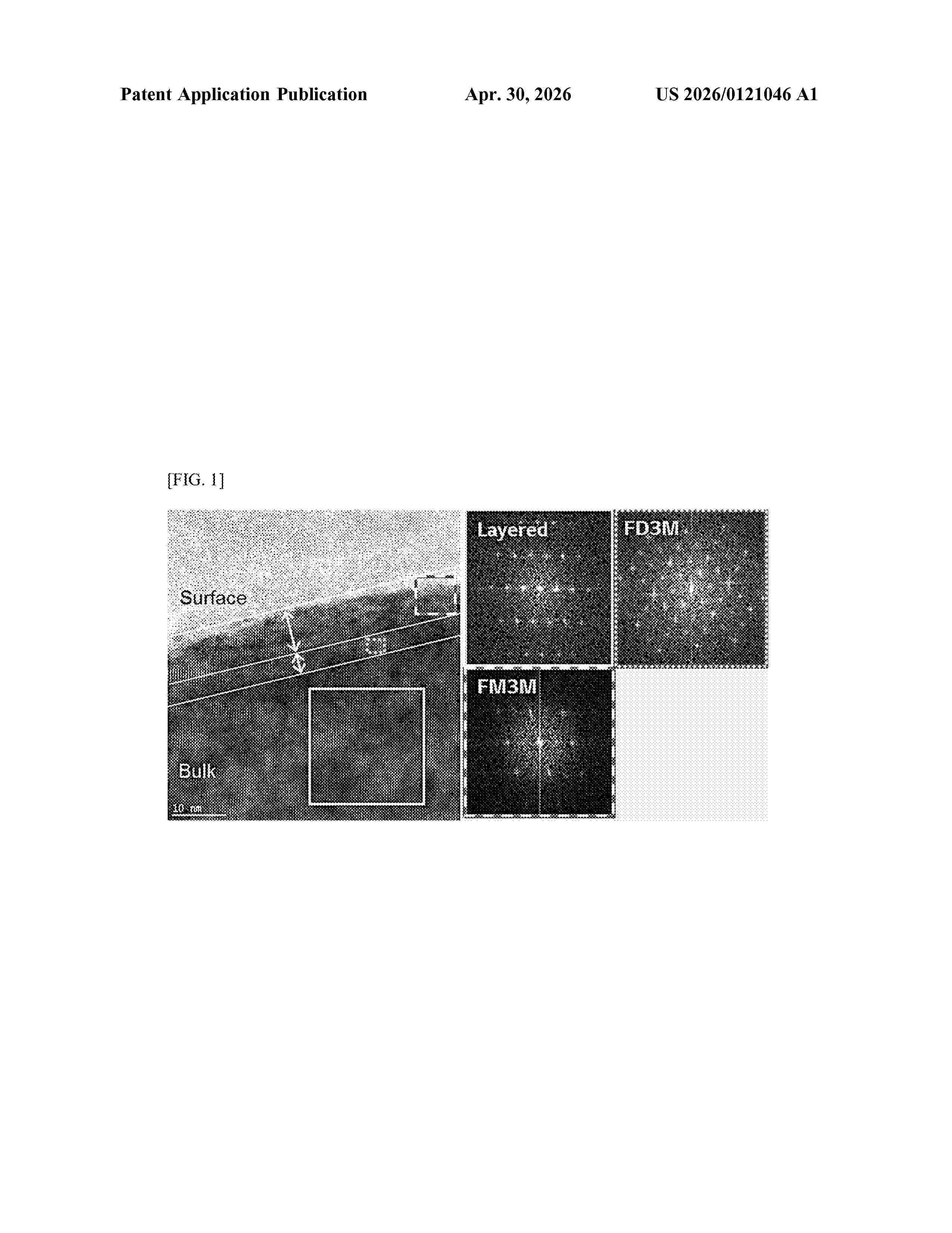
Resumen de: US20260121046A1
Provided is a positive electrode active material for a secondary battery, which is a lithium composite transition metal oxide containing nickel, cobalt, and manganese and having a nickel content accounting for 60 mol % or more of metals excluding lithium and is in the form of a single particle having an average particle diameter (D50) of 1 to 10 μm, wherein a 100-nm region from the surface toward the center of a particle of the lithium composite transition metal oxide has crystal structures of a Fd3M space group and a Fm3m space group, and a phase ratio (Fd3M/Fm3m), which is a ratio of the maximum straight length of portions occupied by the crystal structure of the Fd3M space group and the crystal structure of the Fm3m space group, is 0.2 to 0.7, as determined in a cross-sectional image file of the particle surface part of the lithium composite transition metal oxide particle, which is obtained using transmission electron microscopy (TEM).
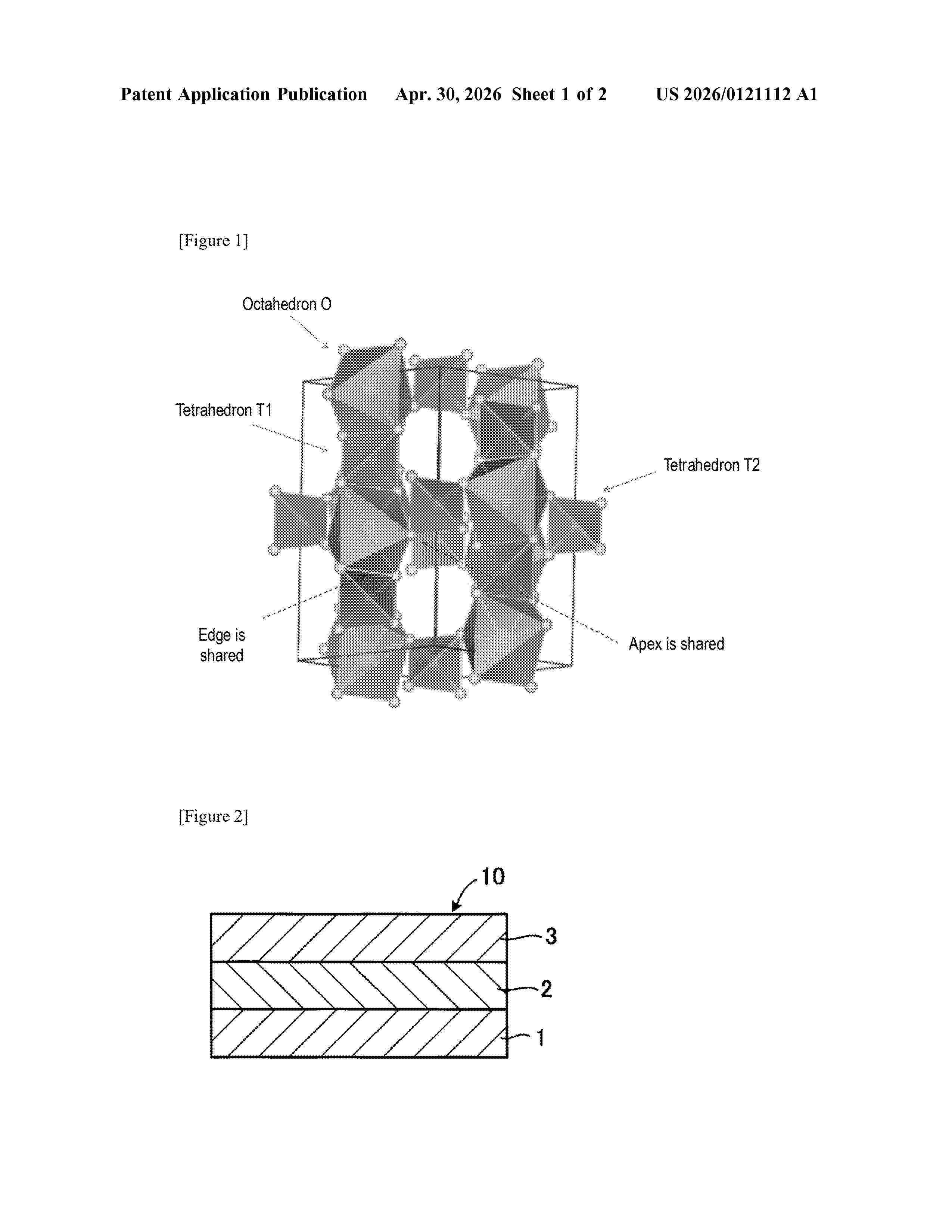
Resumen de: US20260121112A1
The present invention can provide a method for producing a sulfide solid electrolyte, the method characterized by including: a solution preparation step for preparing a uniform solution that includes at least elemental lithium (Li), elemental tin (Sn), elemental phosphorus (P), and elemental sulfur (S) in an organic solvent; a drying step for removing the organic solvent from the uniform solution to obtain a precursor; and a heat treatment step for heat-treating the precursor to obtain a sulfide solid electrolyte.
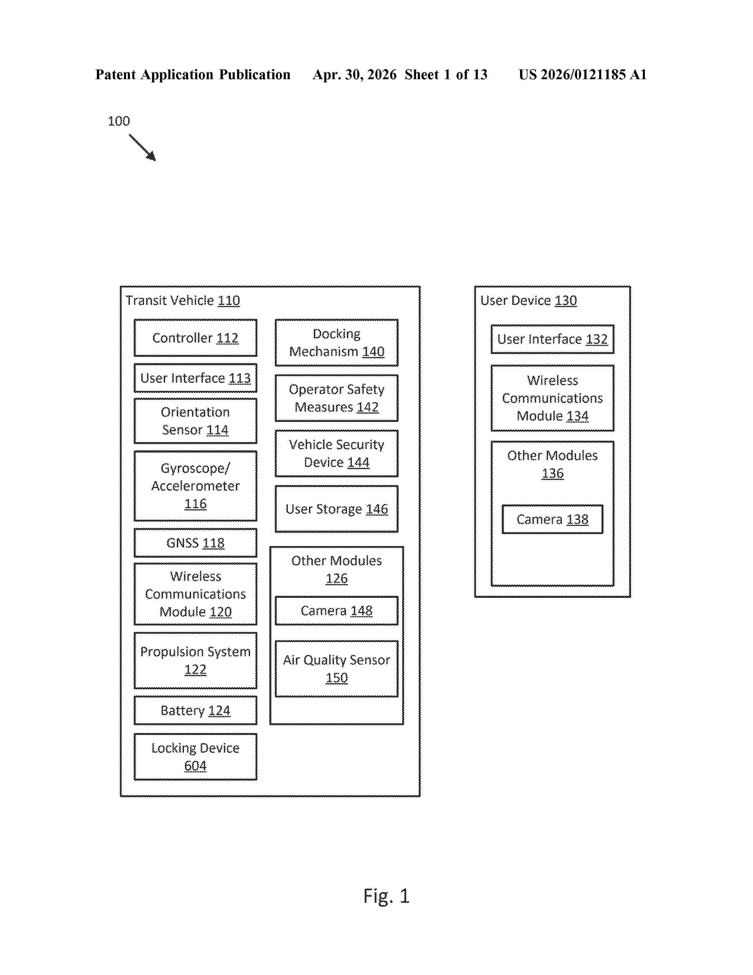
Resumen de: US20260121185A1
Systems and methods related to securing batteries to micro-mobility transit vehicles are disclosed. In one embodiment, a method for securing a battery of a micro-mobility transit vehicle includes connecting a first electrical interface of the battery with a second electrical interface of a battery compartment in which to place the battery. The method includes inserting a mechanical interface extending from the battery into a receiving interface defined in a side of the battery compartment of the micro-mobility transit vehicle. The method includes placing the battery within the battery compartment. The method includes rotating a battery compartment door to a closed position. The method includes engaging locking cams at a first end of the battery compartment door to secure the battery compartment door in the closed position and the battery within the battery compartment.
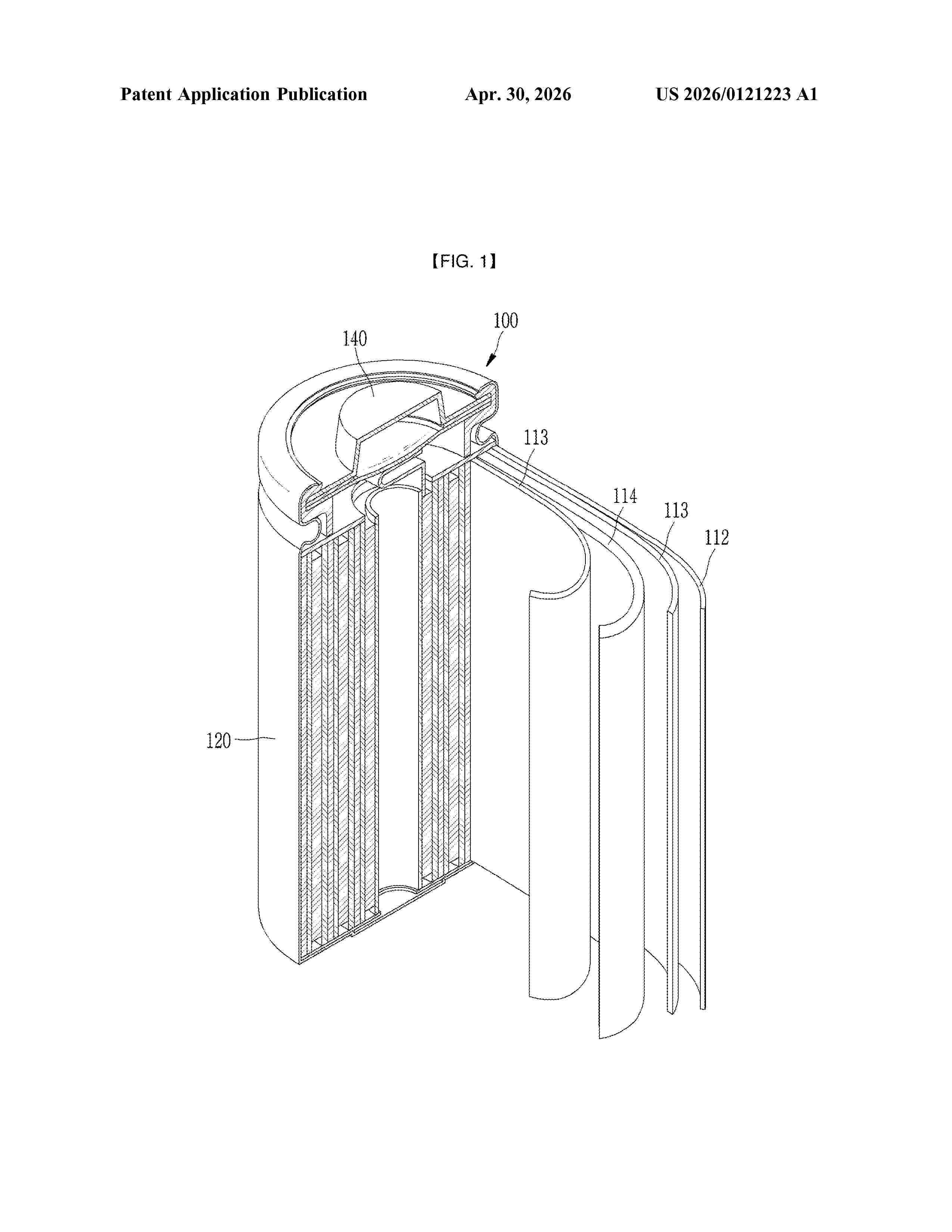
Resumen de: US20260121223A1
A separator for a rechargeable lithium battery including a porous substrate and a heat resistant layer on at least one surface of the porous substrate is disclosed. The heat resistant layer includes a crosslinked binder and a filler, the crosslinked binder includes a crosslinked polymer of an urethane-based compound including at least three curable functional groups and having a molecular weight of greater than or equal to about 10,000, and a (meth)acrylate-based compound including at least two curable functional groups and a molecular weight of less than or equal to about 1,000. The filler includes silica particles having a functional group on the surface. The functional group is selected from a (meth)acrylate group, a vinyl group, a hydroxy group, an epoxy group, an oxane group, an oxetane group, an ester group, and an isocyanate group. A rechargeable lithium battery including the separator is also disclosed.
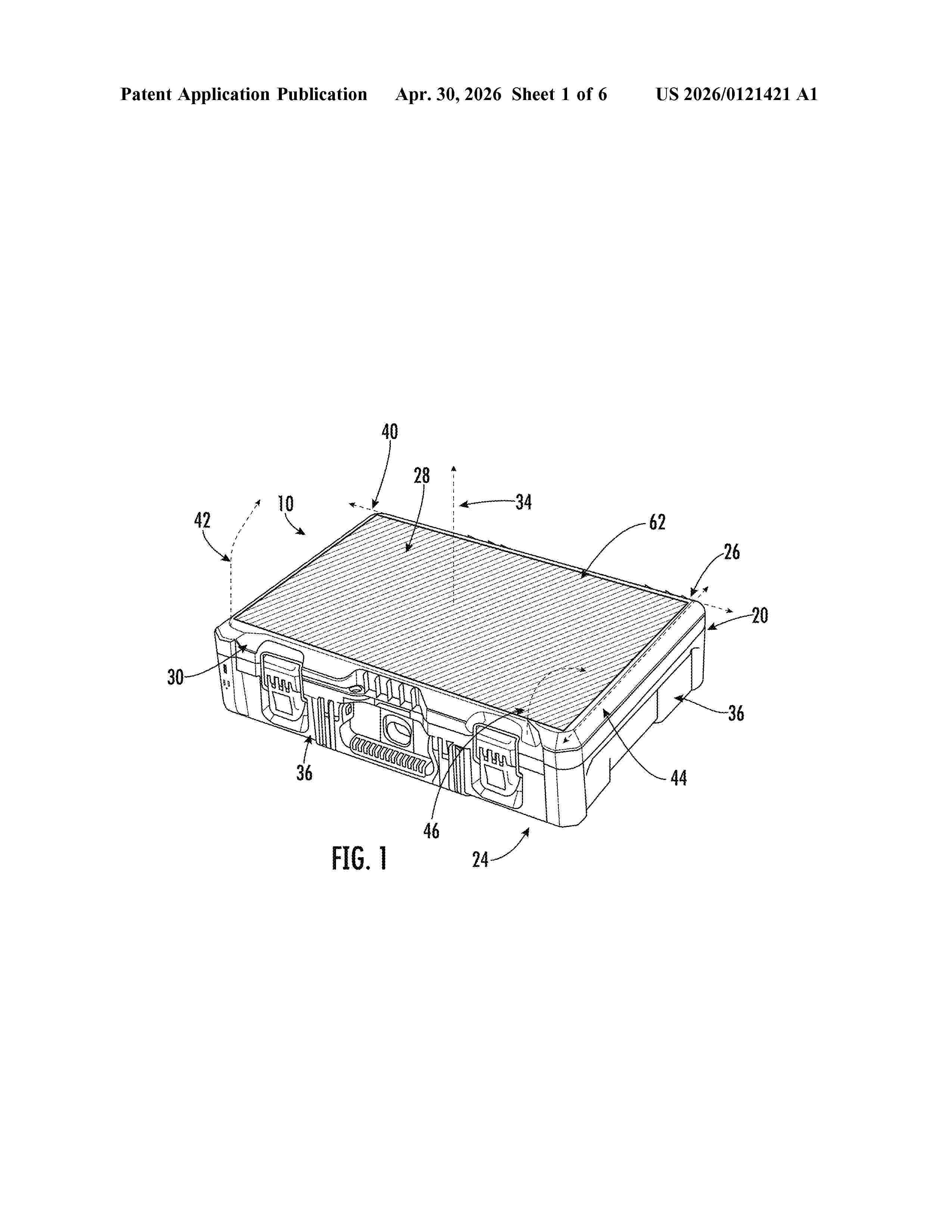
Resumen de: US20260121421A1
A stackable power supply device, container or unit is provided. The power supply device includes an energy conversion module, such as a solar panel. The power supply device includes several power outlets, such as an interface to recharge rechargeable batteries for power tools, an electrical outlet, and a battery to store energy generated by the solar panel. The power supply device is stackable within a modular storage system.
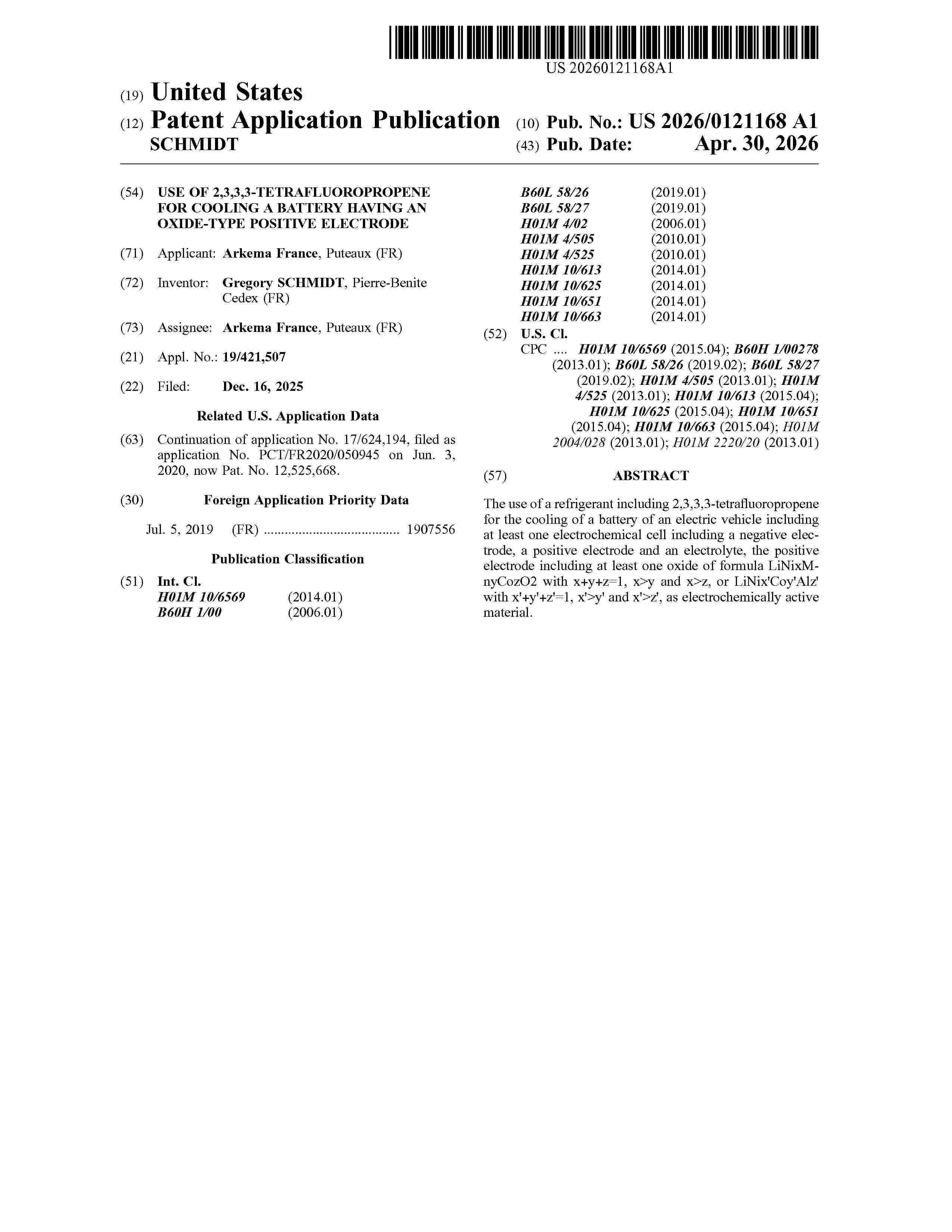
Resumen de: US20260121168A1
The use of a refrigerant including 2,3,3,3-tetrafluoropropene for the cooling of a battery of an electric vehicle including at least one electrochemical cell including a negative electrode, a positive electrode and an electrolyte, the positive electrode including at least one oxide of formula LiNixMnyCozO2 with x+y+z=1, x>y and x>z, or LiNix′Coy′Alz′ with x′+y′+z′=1, x′>y′ and x′>z′, as electrochemically active material.
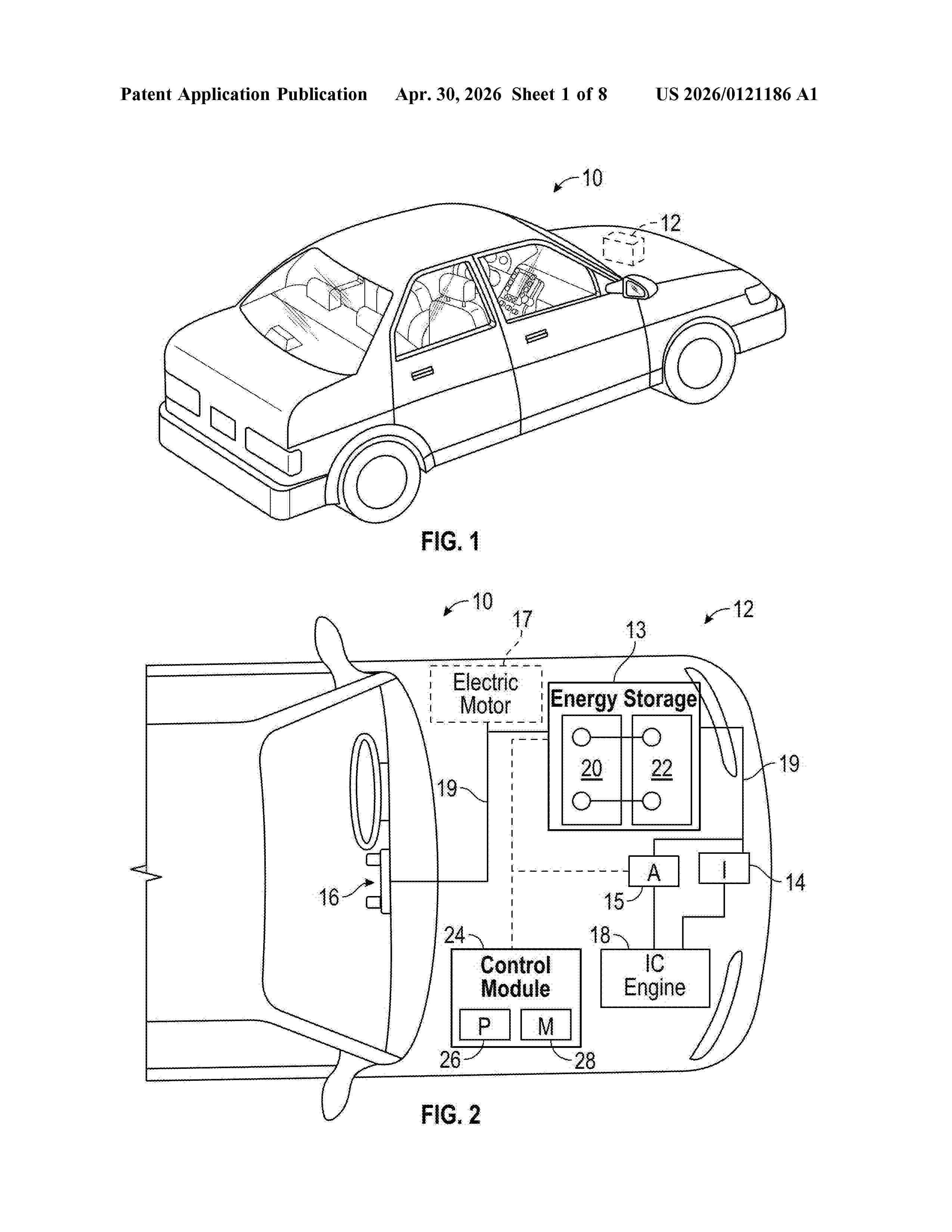
Resumen de: US20260121186A1
A bus bar for a battery module is disclosed. The bus bar has a base and a sidewall. The sidewall includes a folded configuration forming a dual wall. The dual wall includes a center projection. One or more stress-relief features are provided on the sidewall. A plurality of terminal receivers are provided on the base and configured to couple to a plurality of battery terminals. A battery module including a bus bar is also disclosed.
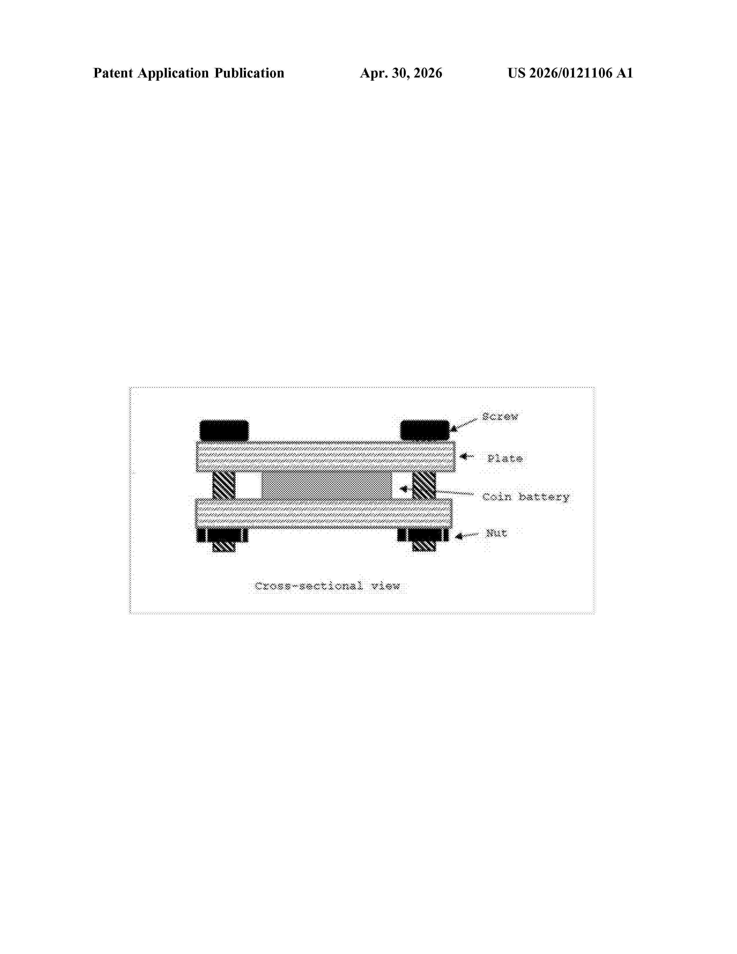
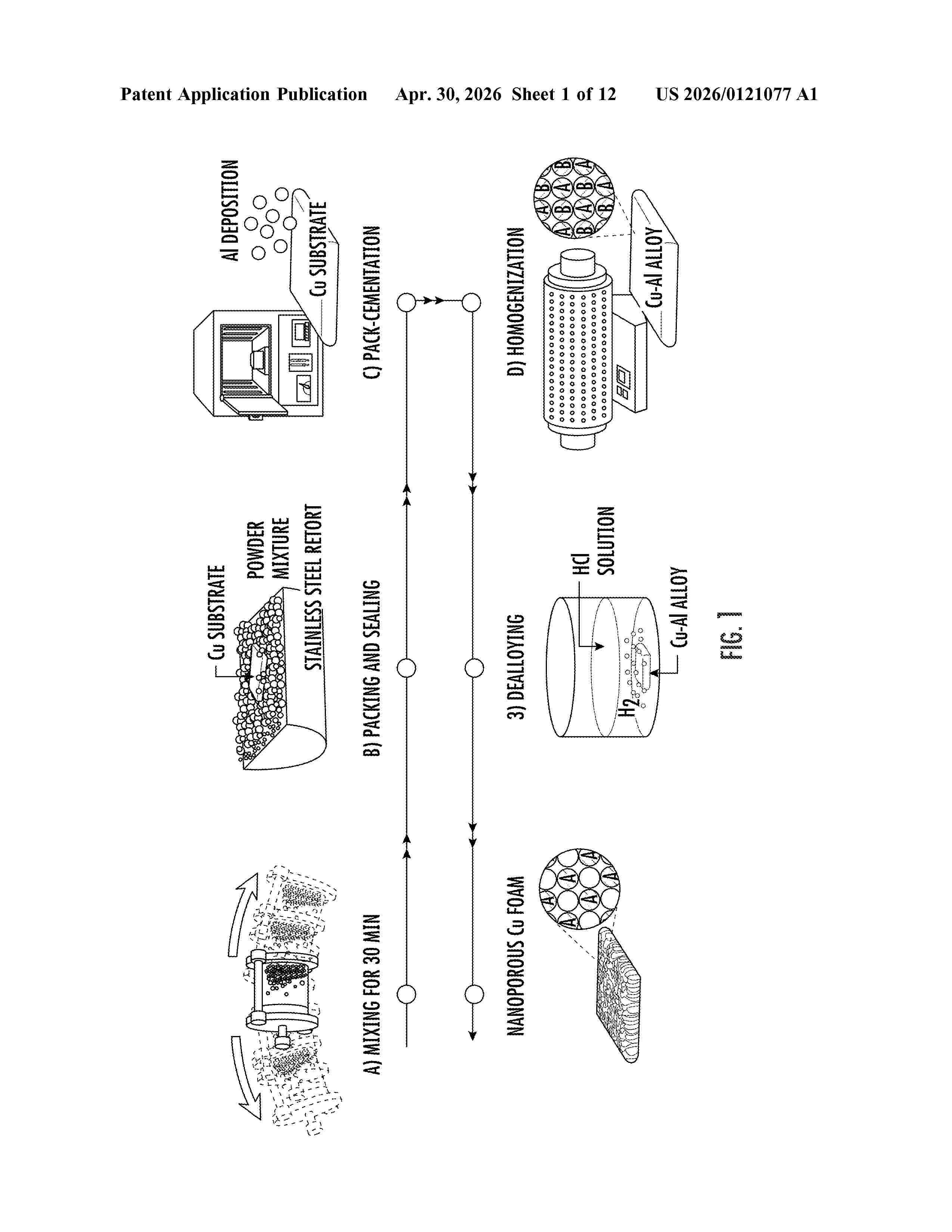
Resumen de: US20260121077A1
0000 A facile method is based on a pack-cementation process using large-area copper foil instead of copper powder. By controlling a pack-cementation time and an amount of alloying element (e.g., aluminum), a hierarchical microporous or nanoporous copper can be created. When coated with tin active material, the hierarchical microporous or nanoporous copper can be used as an advanced lithium-ion battery anode. A coin-cell test exhibited a four-fold higher areal capacity (e.g., 7.4 milliamp-hours per square centimeter without any performance degradation up to 20 cycles) as compared to a traditional graphite anode.
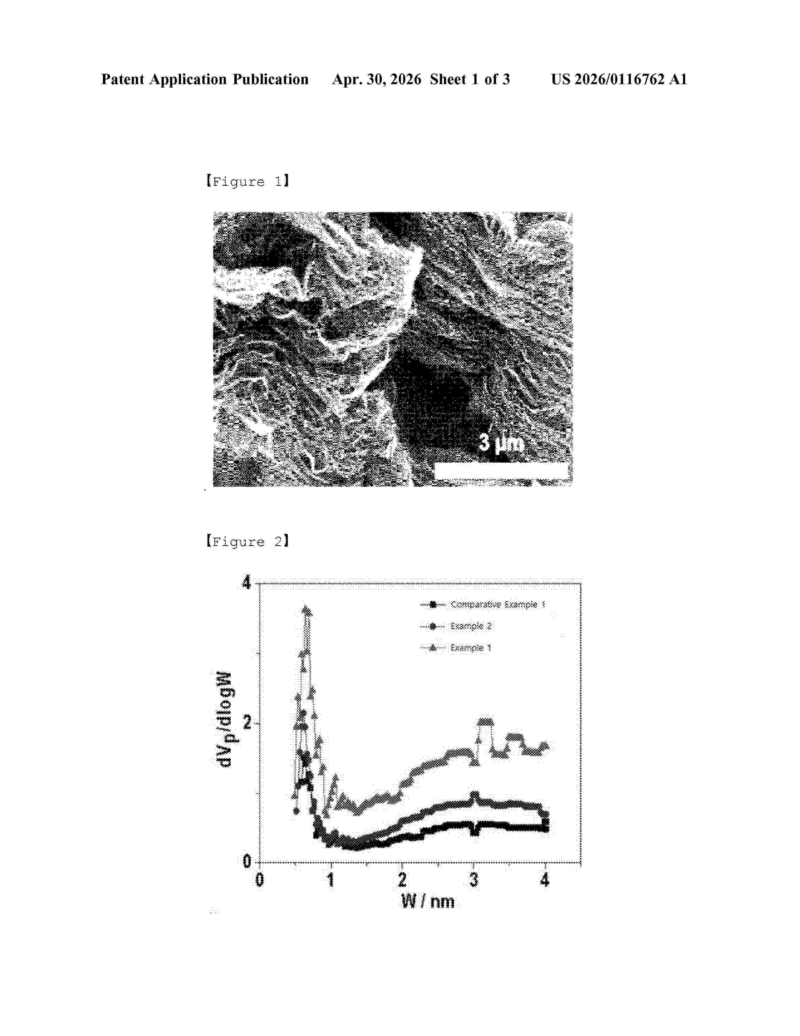
Resumen de: US20260116762A1
A holey thermally expanded-reduced graphene oxide having high specific surface area and pore volume including pores on the surface, a method for preparing the same, and a sulfur-carbon composite and a lithium secondary battery including the same.
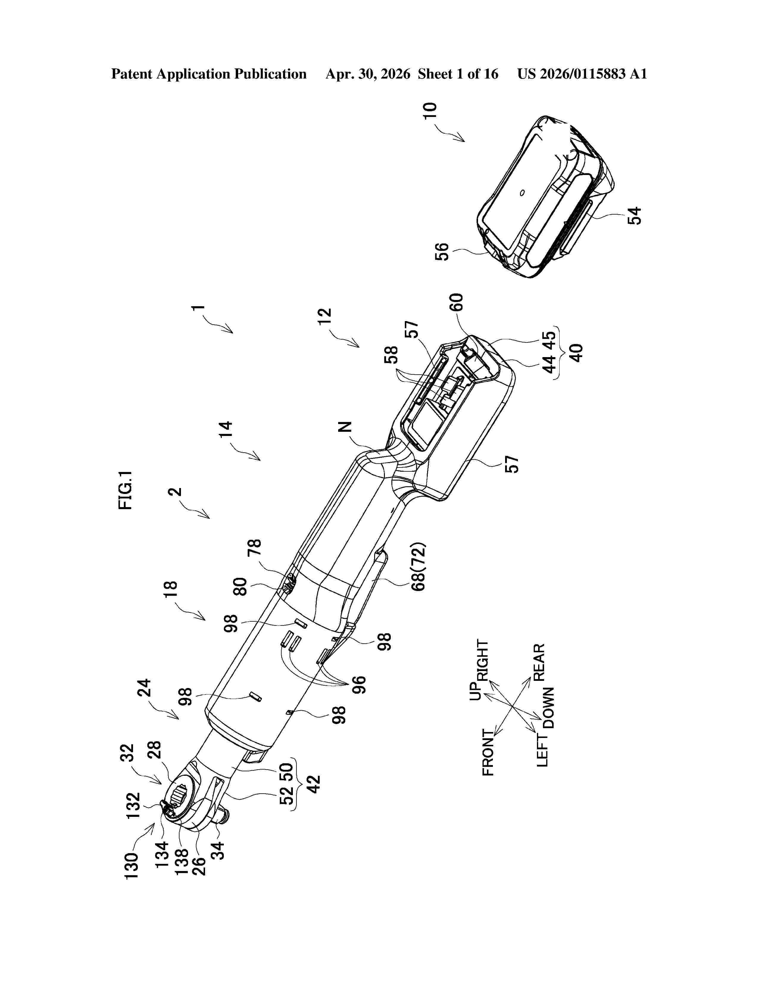
Resumen de: US20260115883A1
An electric ratchet wrench as one example of the ratchet wrench includes an electric motor, a holder that rotatably holds a socket via a one-way clutch mechanism, and a spindle configured to convert a driving force from the motor into a reciprocating rotation motion of the holder. A space is provided between the socket and the holder. The space includes large interval portions and small interval portions. The small interval portions are adjacent to the large interval portions in a rotation direction (lock direction) of the socket and have distances smaller than distances of the large interval portions. Additionally, the one-way clutch mechanism includes columnar locking pins disposed between the spaces and have a diameter with a size equal to or less than the distances of the large interval portions and exceeding the distances of the small interval portions.
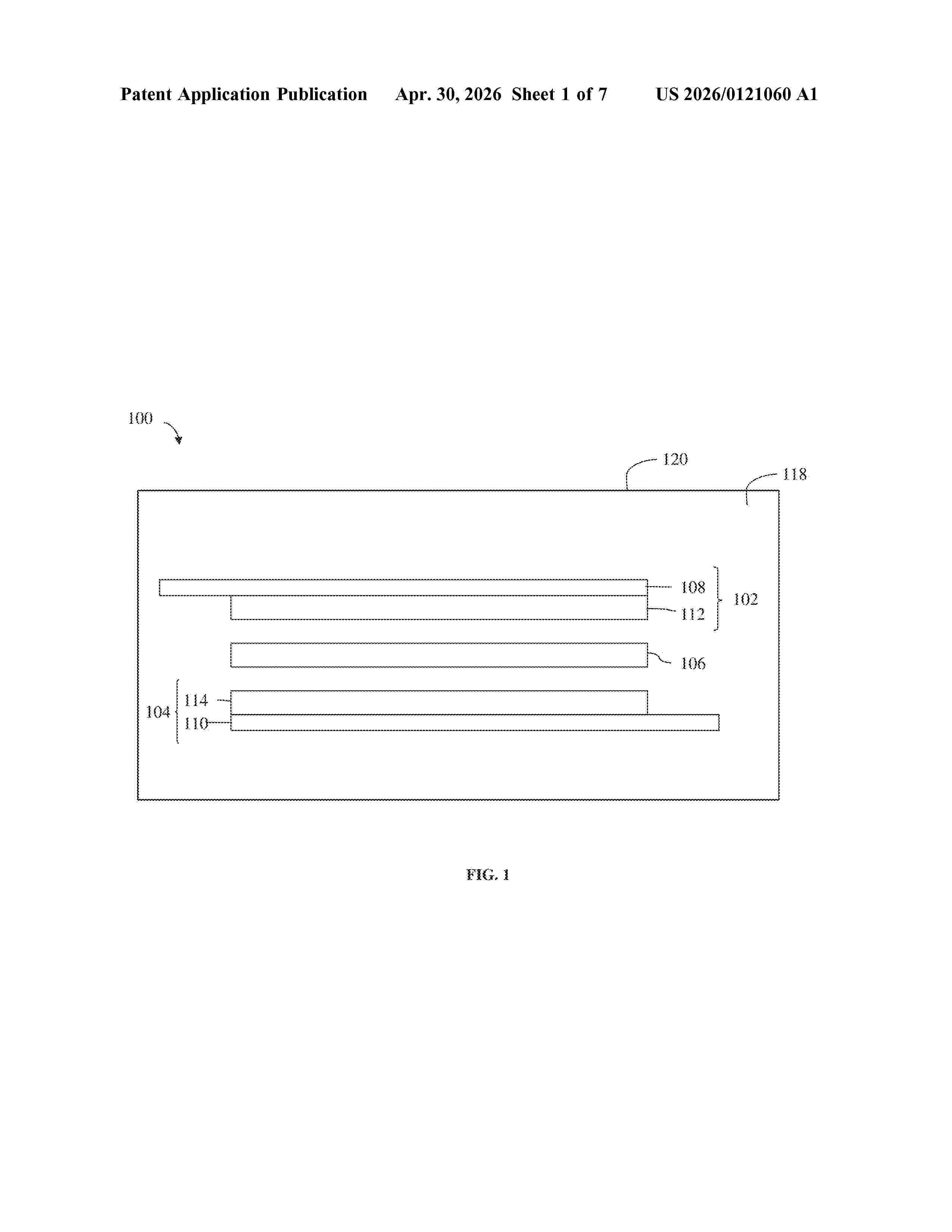
Resumen de: US20260121060A1
Provided herein are dry process electrode films, and energy storage devices incorporating the same, including a microparticulate non-fibrillizable binder having certain particle sizes. The electrode films exhibit improved mechanical and processing characteristics. Also provided are methods for processing such microparticulate non-fibrillizable electrode film binders, and for incorporating the microparticulate non-fibrillizable binders in electrode films.
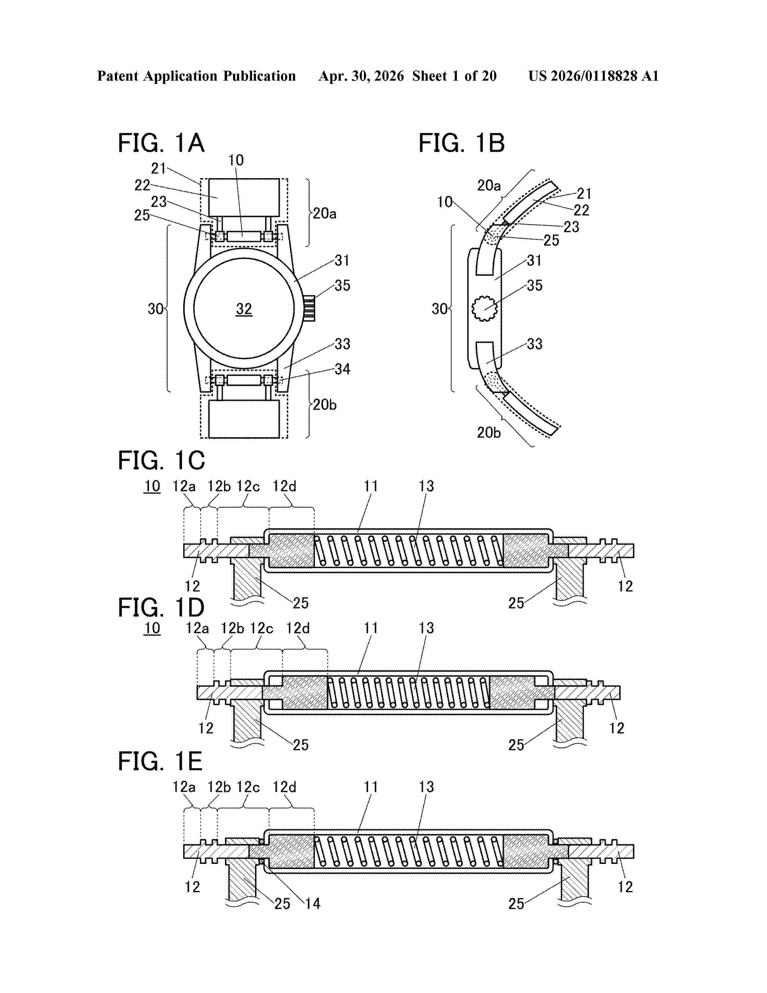
Resumen de: US20260118828A1
A device capable of being used for a long time is achieved. A power supply, a connection method of a power supply, or a connecting member, for easy attachment and detachment and non-detachment when in use, is provided. A power supply, a connection method of a power supply, or a connecting member for easy replacement is provided. A highly designed power supply is provided. Power from a battery is supplied to an electronic device through a connecting member including a pipe, a spring, and a pair of pivots. The pair of pivots are electrically insulated from each other, and electrically connected to any one of a pair of electrodes of the battery. The electronic device into which the pair of pivots are inserted includes a pair of bearings capable of receiving power.
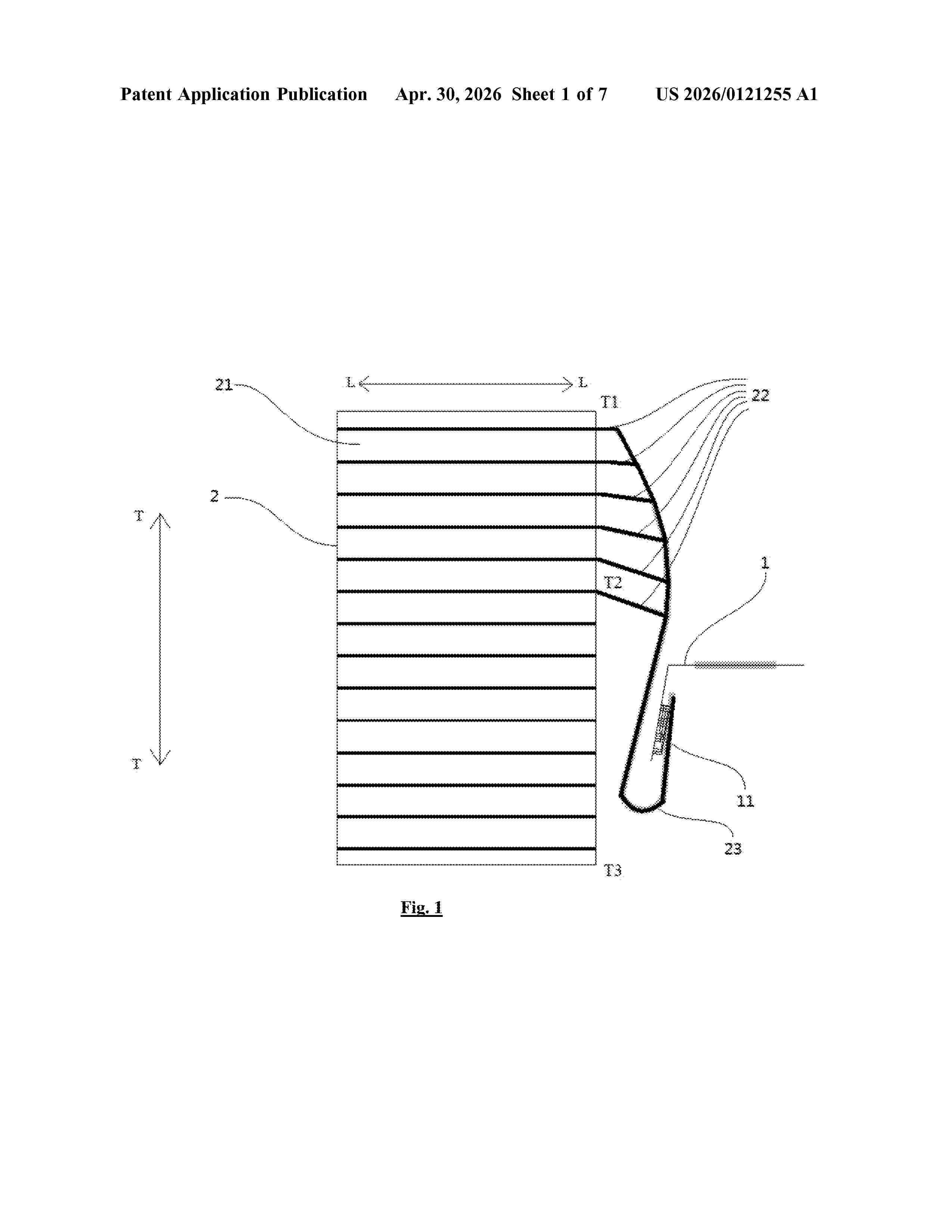
Resumen de: US20260121255A1
The present application relates to a secondary battery including a first adapter piece and an electrode assembly, the electrode assembly including a first electrode plate, a second electrode plate, a plurality of electrode tabs and a second electrode tab, all of the first electrode tabs are stacked to form a first multi-tab structure and connected to the first adapter piece, and the electrode assembly comprises a first adapter member; the first adapter member comprises the first multi-tab structure and the first adapter piece; in a direction parallel to the first electrode plate, there is at most one layer of the first adapter member. The present application may effectively reduce the existing waste of the top space caused by bending the electrode tabs, and is more stable for the bending effect, thereby improving the energy density of the battery.
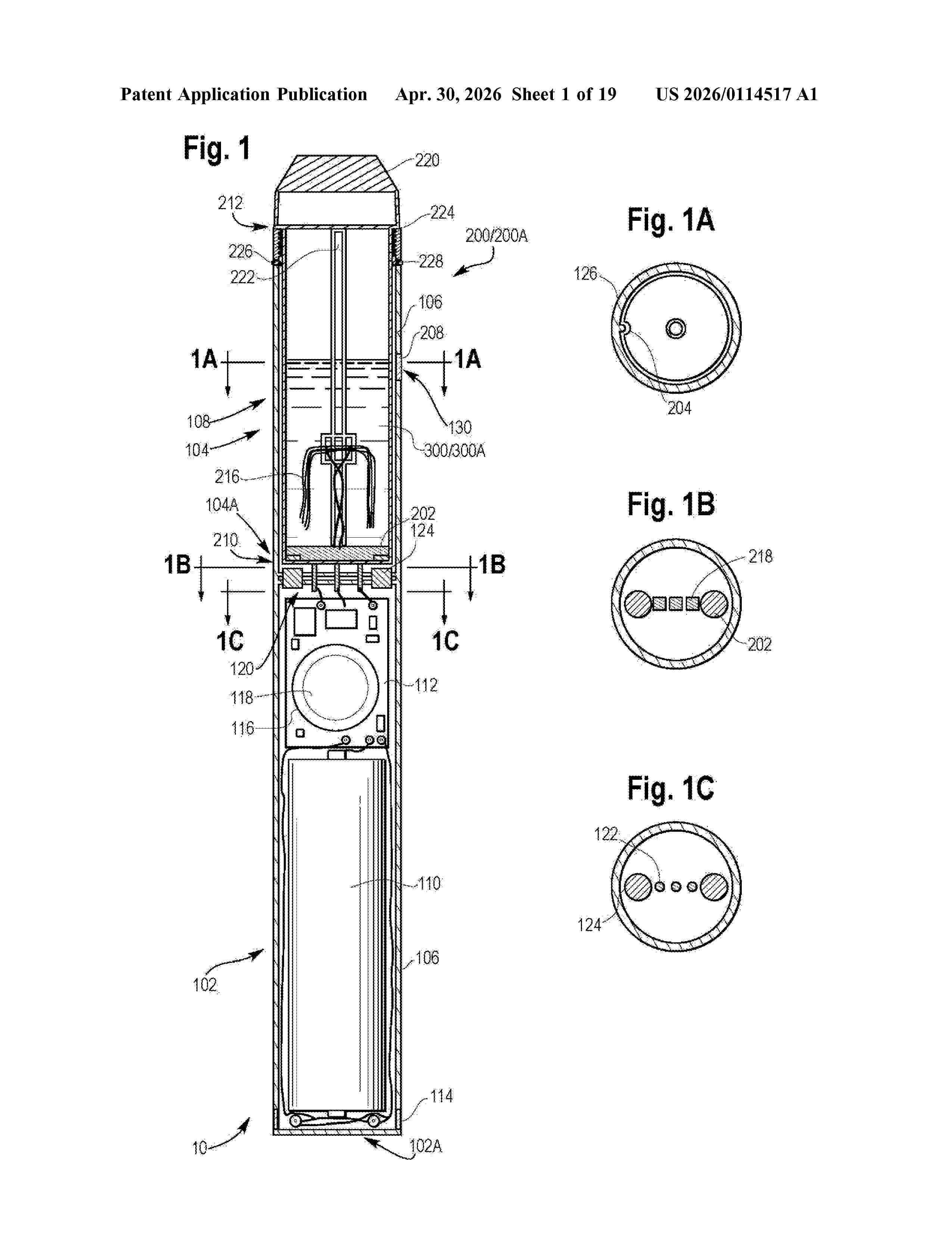
Resumen de: US20260114517A1
An electronic cigarette or vaporizer may include a shell and a cartomizer receivable within a chamber within a portion of the shell. A basin may be included in the cartomizer to hold a vaporizable fluid, dry substance, or other vaporizable substance such as a wax. A heating element may be provided within the basin which may have a flexible non-conductive material and a flexible conductive material.
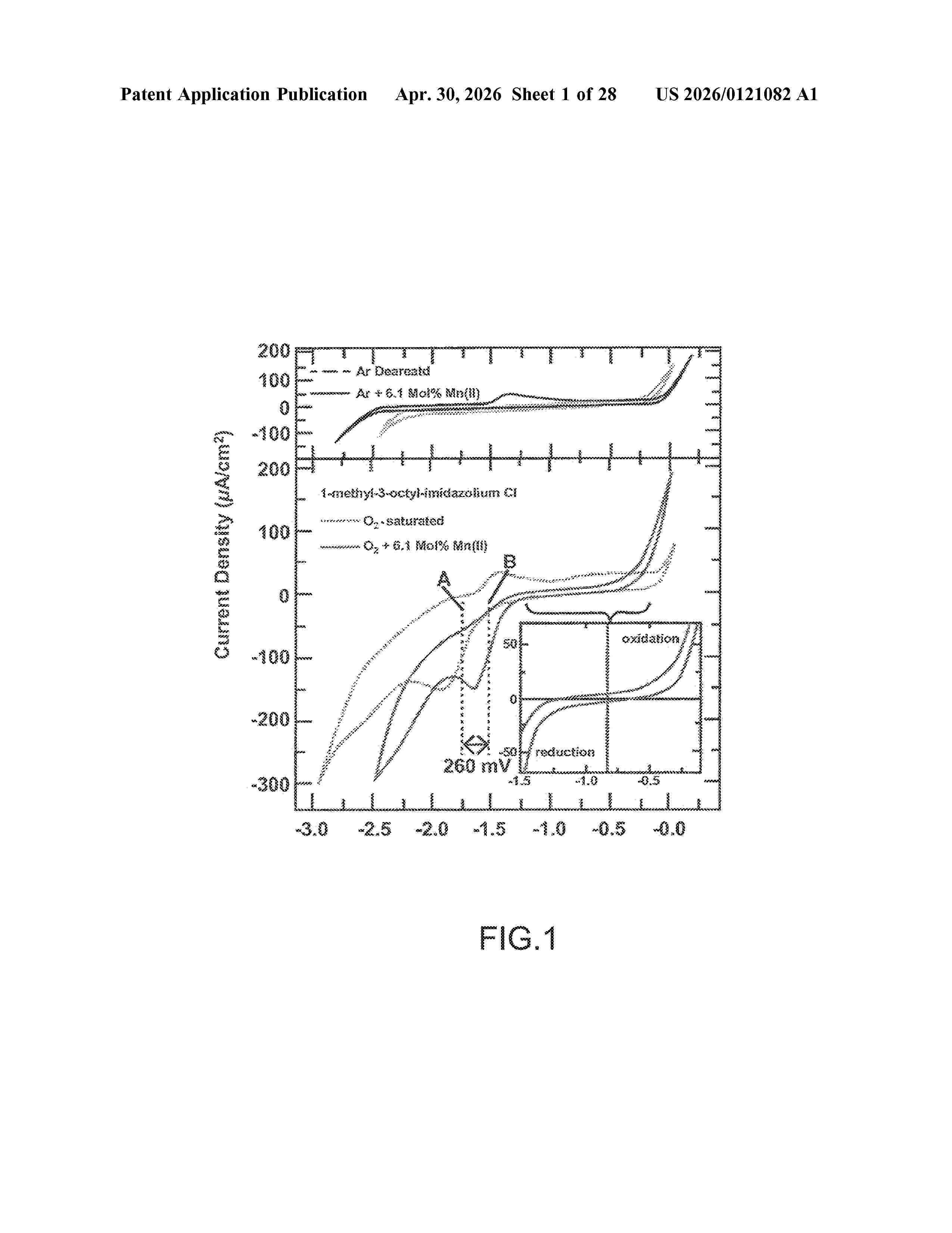
Resumen de: US20260121082A1
Systems and methods drawn to an electrochemical cell comprising a low temperature ionic liquid comprising positive ions and negative ions and a performance enhancing additive added to the low temperature ionic liquid. The additive dissolves in the ionic liquid to form cations, which are coordinated with one or more negative ions forming ion complexes. The electrochemical cell also includes an air electrode configured to absorb and reduce oxygen. The ion complexes improve oxygen reduction thermodynamics and/or kinetics relative to the ionic liquid without the additive.
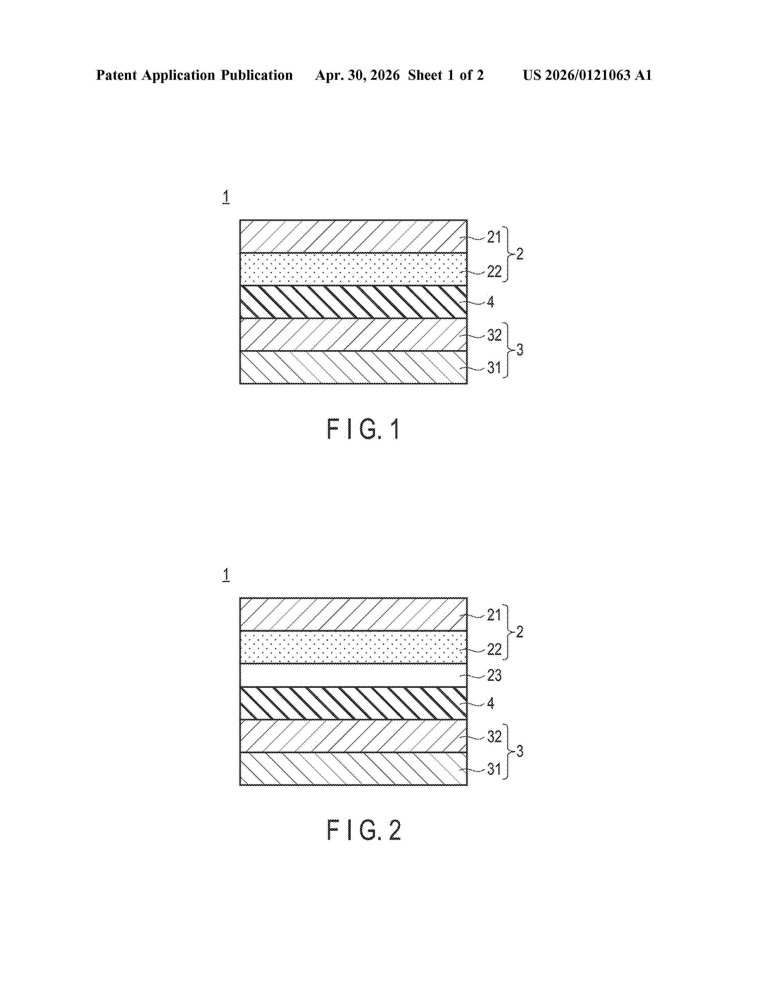
Nº publicación: US20260121063A1 30/04/2026
Solicitante:
ABRI CO LTD [JP]
ABRI Co., Ltd.
Resumen de: US20260121063A1
One embodiment of the present application provides a lithium-sulfur battery positive electrode including a positive electrode current collector and a sulfur layer deposited on a surface of the positive electrode current collector, wherein the sulfur layer contains sulfur and/or a sulfur compound which is a main positive electrode active material, a lithium-containing oxide, and a nitrogen-containing organic compound, and the nitrogen-containing organic compound is a nitrogen-containing heterocyclic compound.
 BOPI
BOPI
 Sede Electrónica