Si deseas distinguir tus productos, servicios o ambos de los de otra empresa, es posible que necesites una marca o nombre comercial. Descubre qué son, en qué consiste su procedimiento de registro y qué implica.

Información sobre los plazos de presentación de solicitudes de transformación de marcas de la Unión Europea en marca nacional española. Más información


Si tienes un nuevo dispositivo, producto o procedimiento que resuelva un problema técnico o tenga una ventaja práctica, existen distintas formas de protegerlo en España y en otros países. Descubre cómo hacerlo.

¿Tu innovación reside en la estética, la ornamentación o la apariencia de tu producto? Protégela mediante un diseño industrial. Descubre qué derechos confiere el registro y cómo realizar la tramitación.

Las indicaciones geográficas protegen el nombre de un producto originario de una zona geográfica, a la cual le debe una determinada calidad, reputación u otra característica. Descubre qué son, en qué consiste su procedimiento de registro y qué beneficios conceden.

Las patentes publicadas en todo el mundo son una valiosa fuente de información científica, técnica y comercial.

Si eres emprendedor/a o una empresa y quieres potenciar y mejorar la rentabilidad de tu negocio protegiendo de forma adecuada los activos intangibles de tu organización, en este espacio encontrarás lo necesario.


 898
resultados
898
resultados
 Última actualización
07/05/2026 [07:29:00]
Última actualización
07/05/2026 [07:29:00]


 Resultados 25 a 50 de 898

Resumen de: US20260115692A1
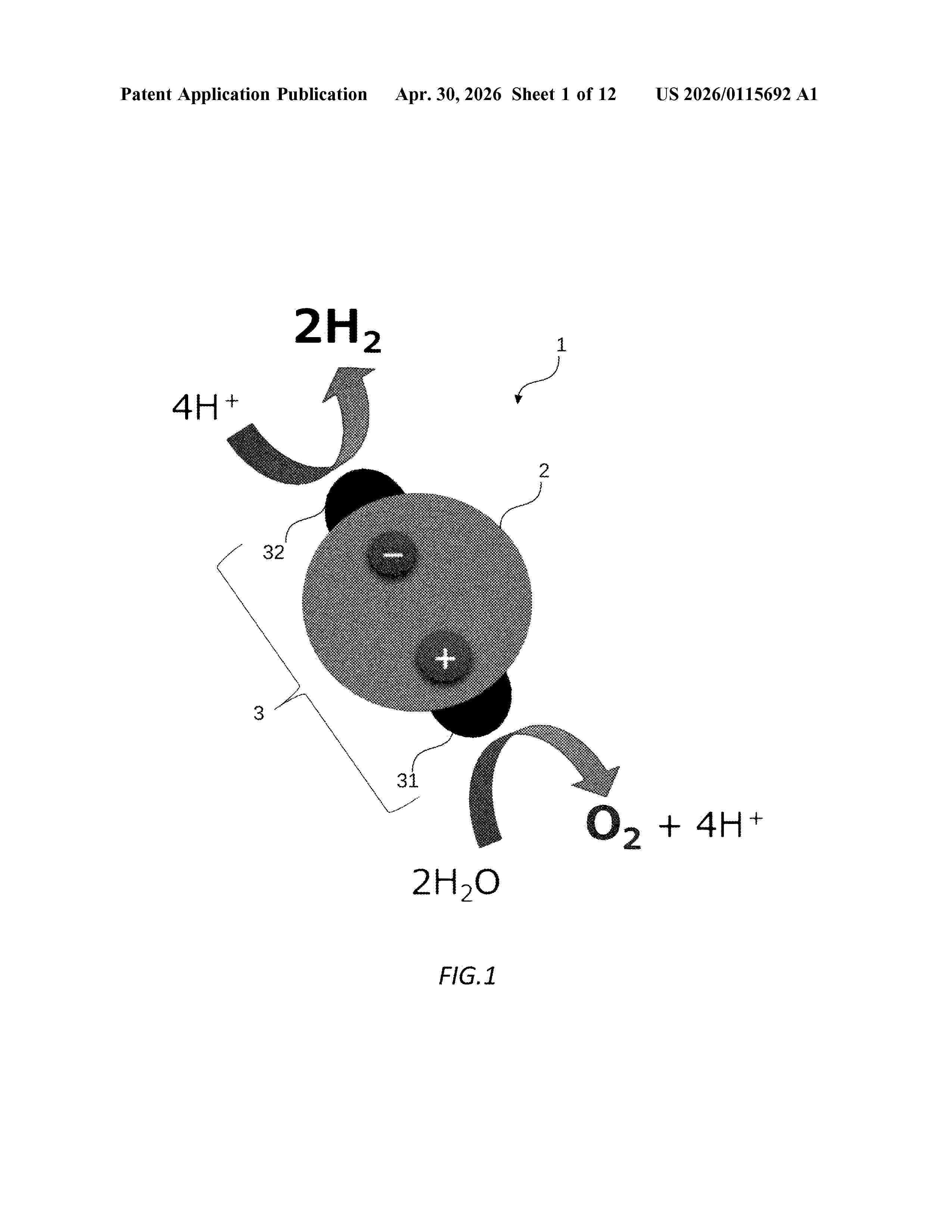
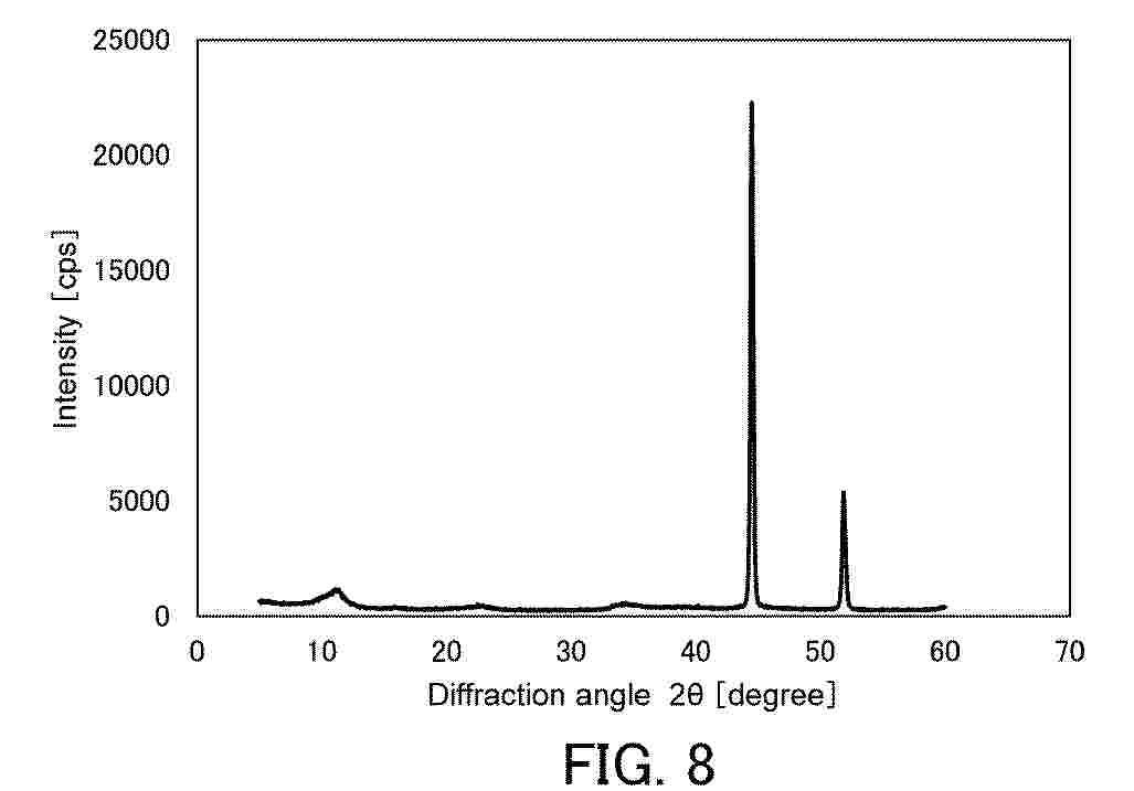
0000 A highly active catalyst particle includes a photocatalyst 2 and a cocatalyst 3 supported on the photocatalyst 2, in which the cocatalyst 3 contains a first cocatalyst 31 and a second cocatalyst 32, the first cocatalyst 31 contains at least one of Group 3 to Group 7 elements, the second cocatalyst 32 contains at least one of Group 8 to Group 11 elements, and the photocatalyst 2 contains titanium at 16 at % or more, and decomposes water under light irradiation to generate hydrogen and oxygen.

Resumen de: US20260117404A1
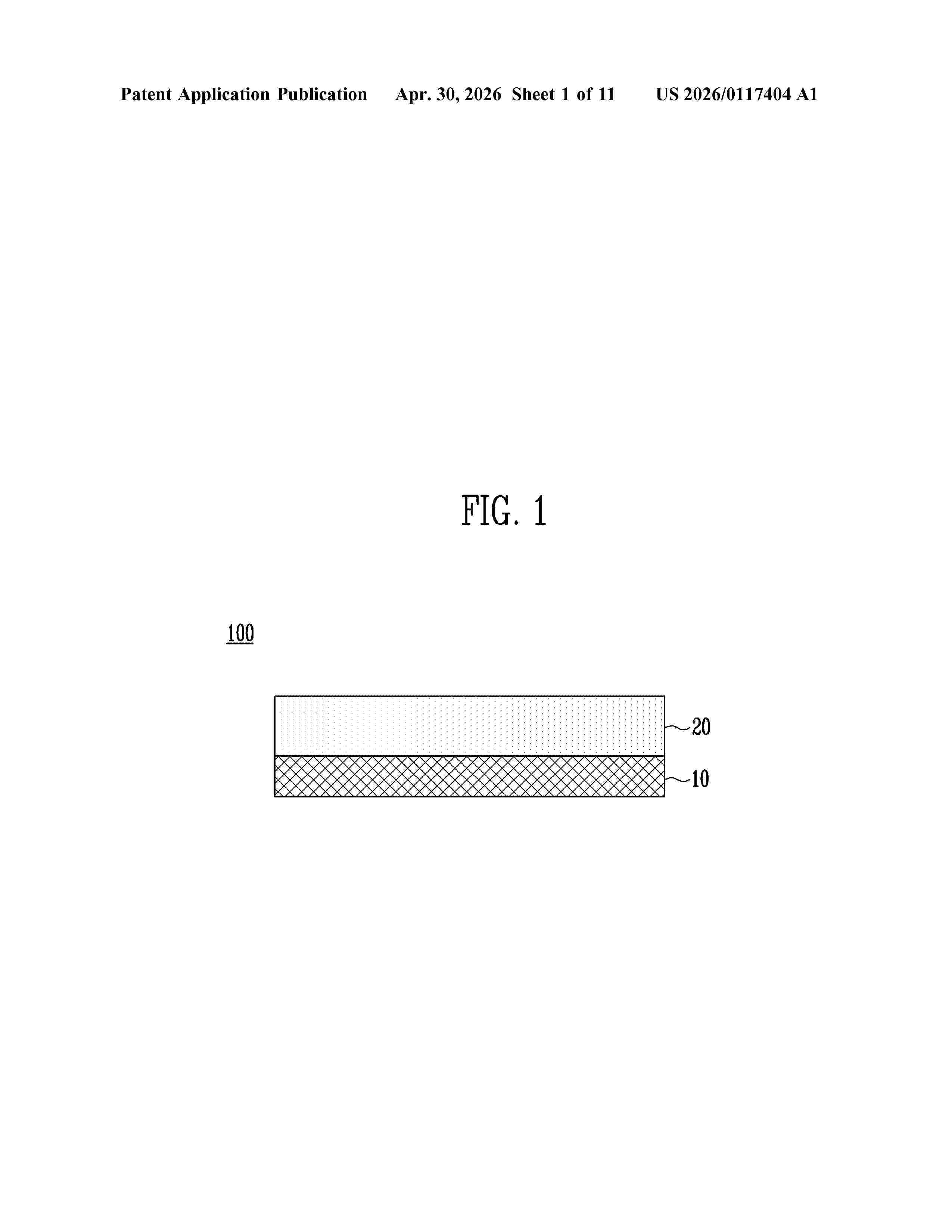
0000 The embodiments of the present disclosure relate to a water electrolysis electrode, manufacturing method of the water electrolysis electrode, and water electrolysis device. In an embodiment, the water electrolysis electrode may comprise a metal layer and a catalyst layer disposed on the metal layer, wherein the catalyst layer may include silver, iridium and ruthenium.
Resumen de: WO2026087350A1
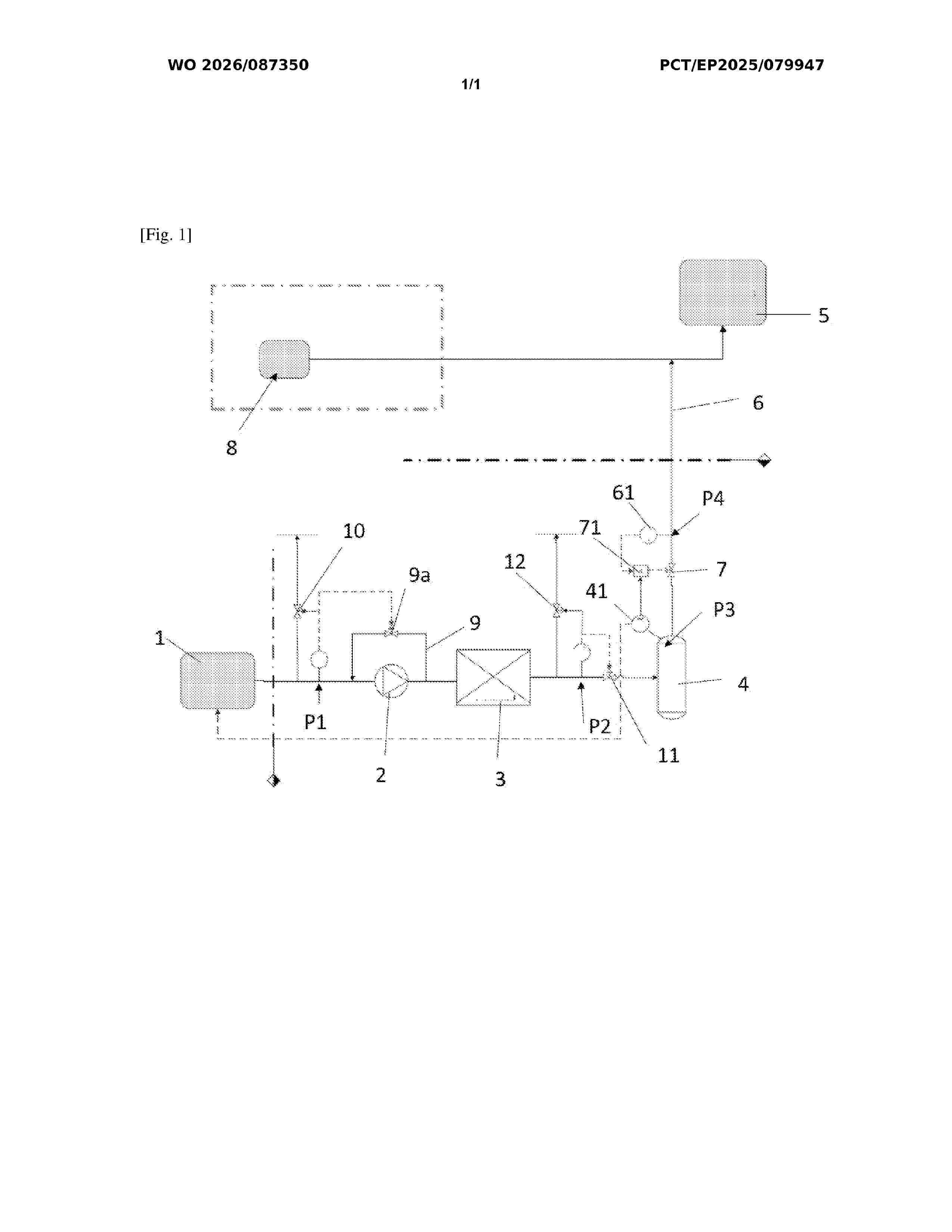
The present invention relates to the field of industrial production of dihydrogen and more particularly to a dihydrogen production installation (H2) intended to supply an installation using dihydrogen and a method for controlling said installation.
Resumen de: WO2026088471A1
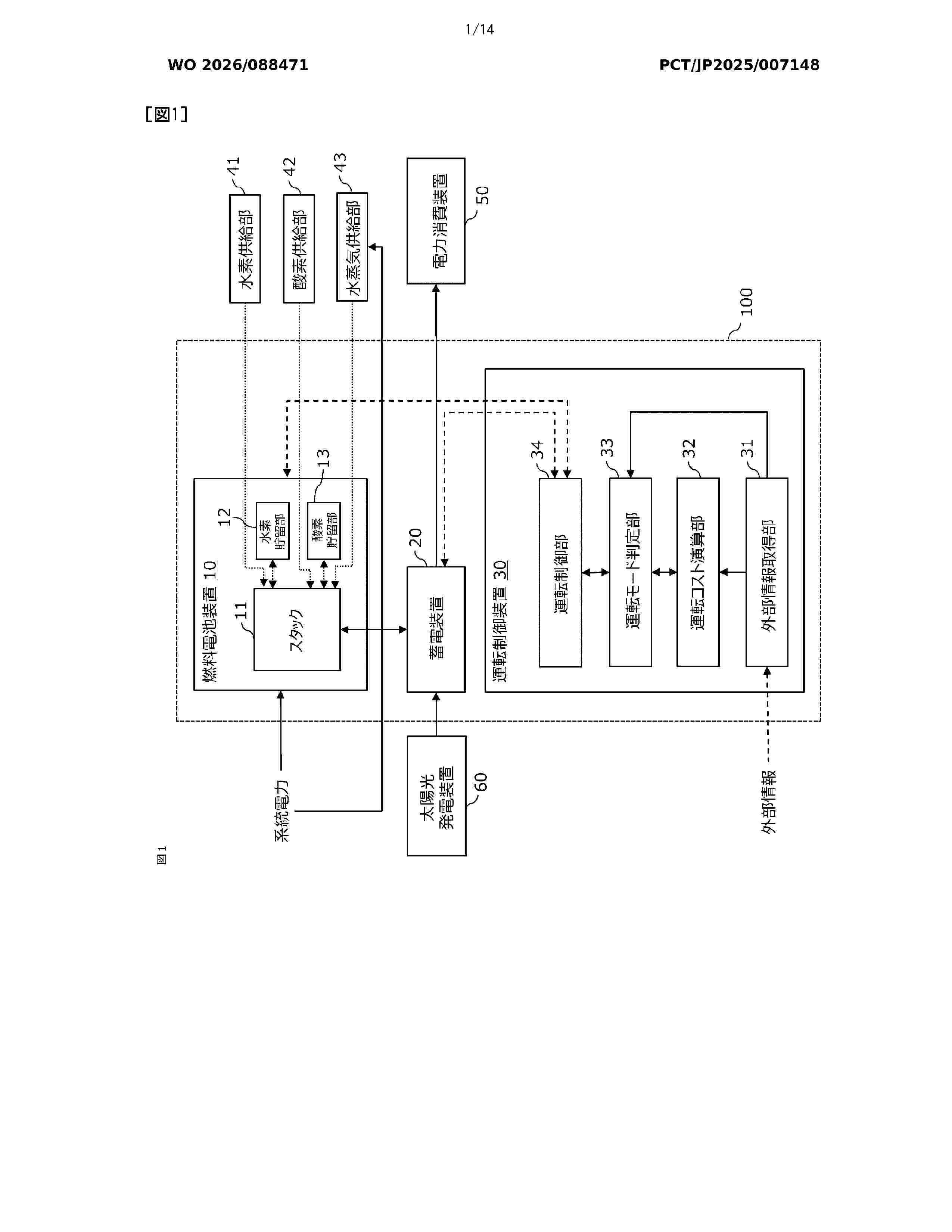
This operation control device, which controls the operation of a fuel cell device, is configured to comprise: an external information acquisition unit that acquires external information including market electricity and hydrogen prices used to operate the fuel cell device; an operation cost calculation unit that calculates power generation cost in a fuel cell mode using the hydrogen price, hydrogen generation cost in an electrolysis mode using the electricity price, operation switching profit based on the power generation cost or the hydrogen generation cost, and operation switching loss resulting from switching between the fuel cell mode and the electrolysis mode; an operation mode determination unit that determines to switch the operation mode when the difference between the operation switching profit and the operation switching loss exceeds a determination threshold value; and an operation control unit that controls the operation on the basis of the determination made by the operation mode determination unit.
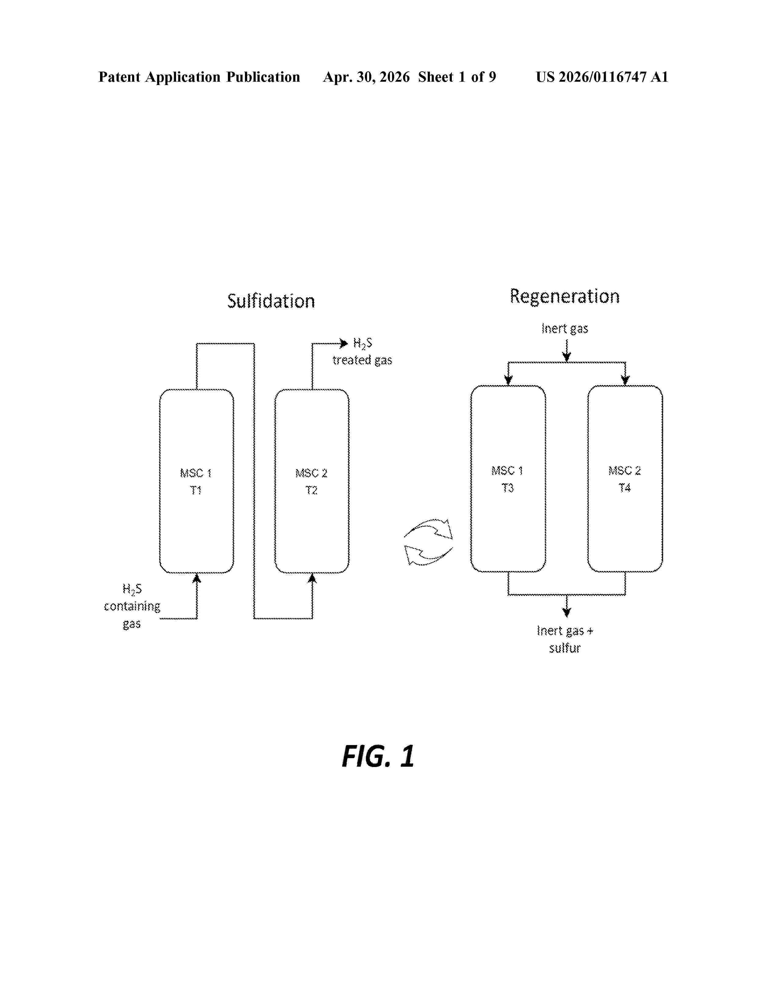
Resumen de: US20260116747A1
A system may include a gas inlet configured to receive a gas stream comprising hydrogen sulfide (H2S), a first particle bed comprising a plurality of first particles, the first particles comprising a support material and a first metal material comprising at least one of: iron (Fe), nickel (Ni), chromium (Cr), cobalt (Co), vanadium (V), copper (Cu), and cerium (Ce); and the first particle bed in fluid communication with the gas inlet. A system may include a second particle bed comprising a plurality of second particles comprising a support material and a second metal material comprising at least one of: iron (Fe), chromium (Cr), nickel (Ni), and vanadium (V), the second particle bed being in fluid communication with the first particle bed. A system may include a gas outlet in fluid communication with the second particle bed, the gas outlet being configured to provide an output stream comprising hydrogen (H2) gas.
Resumen de: WO2024261689A1
Electrolyser device (1), of the type which uses the anion exchange membrane water electrolysis (AEMWE) technology for the production of hydrogen, characterized in that it comprises: - at least one support frame (2) with a substantially laminar development, comprising at least two seats (3) which are defined on the same support frame (2) so as not to overlap with each other, - at least two electrochemical modules (10) wherein: - each electrochemical module (10) is mounted at a respective seat (3), - each electrochemical module (10) includes an anion exchange separation membrane (11) which is interposed between two electrodes, respectively between an anode (12) and a cathode (13), - at least the separation membranes (11 ) of said at least two electrochemical modules (10) are structurally distinct and separated from each other, means (20) for applying electrical energy to the electrodes (12, 13) of each electrochemical module (10).
Resumen de: EP4734316A1
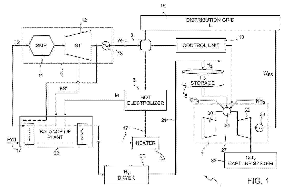
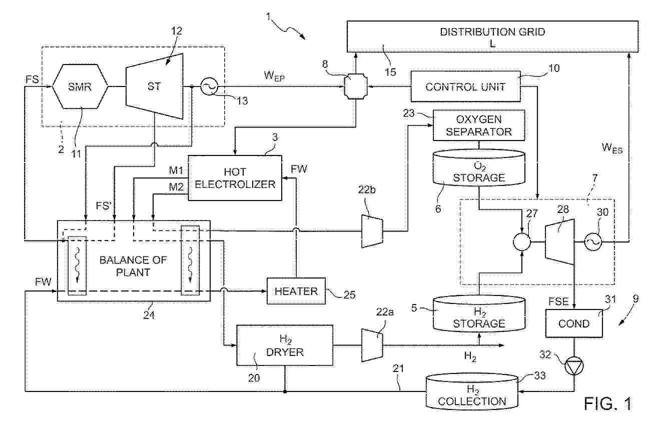
A hybrid power plant includes a nuclear source generator assembly (2), configured to provide a primary electric power (WEP) from a nuclear source; an electrolyzer (3) operable to produce a mixture (M) containing hydrogen from an inlet water flow (FWI) in the vapour and/or liquid phase; a hydrogen storage system (5), coupled to the electrolyzer (3) to receive hydrogen from the mixture (M); and a hydrogen generator assembly (7), operable to produce a secondary electric power (WES) using the hydrogen from the hydrogen storage system (5). A power divider (8), coupled to a distribution grid (15) and to the electrolyzer (3), is configured to controllably divide the primary electric power (WEP) between the distribution grid (15) and the electrolyzer (3) .
Resumen de: EP4733448A1
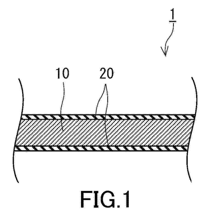
0001 A water electrolysis electrode 1 includes an electroconductive substrate 10 and a layered double hydroxide layer 20. The layered double hydroxide layer 20 is disposed on a surface of the electroconductive substrate 10. The layered double hydroxide layer 20 includes Ni. In a diffraction pattern obtainable by grazing incidence X-ray diffraction measurement of the layered double hydroxide layer, a diffraction peak height P<012> of a (012) plane is higher than a diffraction peak height P<003> of a (003) plane.
Resumen de: EP4733443A1
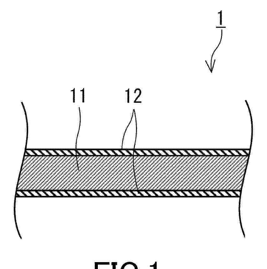
0001 An electrode 1 for water electrolysis cell includes a conductive base 10, a first layer 11, and a second layer 12. The conductive base 10 includes a transition metal. The first layer 11 is disposed on the conductive base 10, and includes two or more transition metals and oxygen. The second layer 12 is disposed on the first layer 11 and includes a layered double hydroxide (LDH) including two or more transition metals. The first layer 11 is disposed between the conductive base 10 and the second layer 12 in a thickness direction of the first layer 11. The first layer 11 includes a first transition metal that is the same as the transition metal included in the conductive base 10, and a second transition metal that is the same as the transition metal included in the second layer 12 and different from the first transition metal. The first transition metal exists in the first layer 11 at a concentration higher than a concentration of the first transition metal in the second layer 12.
Resumen de: WO2025002638A1
The present invention relates to a divided cell for alkaline water electrolysis, where the separator is equipped with a gasket having anisotropic elastic properties and exhibiting reduced gasket deformation along the plane of the major surface of the separator when subject to a compression force perpendicular to that plane. The invention also relates to an electrolyser comprising a plurality of cells as hereinbefore described.
Resumen de: EP4733451A1
A water electrolysis electrode 1 includes an electroconductive substrate 10 and a layered double hydroxide (LDH) layer 20. The layered double hydroxide layer 20 is formed on a surface of the electroconductive substrate 10. An effective film thickness of the layered double hydroxide layer 20 is 250 nm or more and less than 4000 nm. The layered double hydroxide layer 20 may include layered double hydroxide 20a. The effective film thickness of the layered double hydroxide layer 20 may be 3470 nm or less.
Resumen de: EP4733447A1
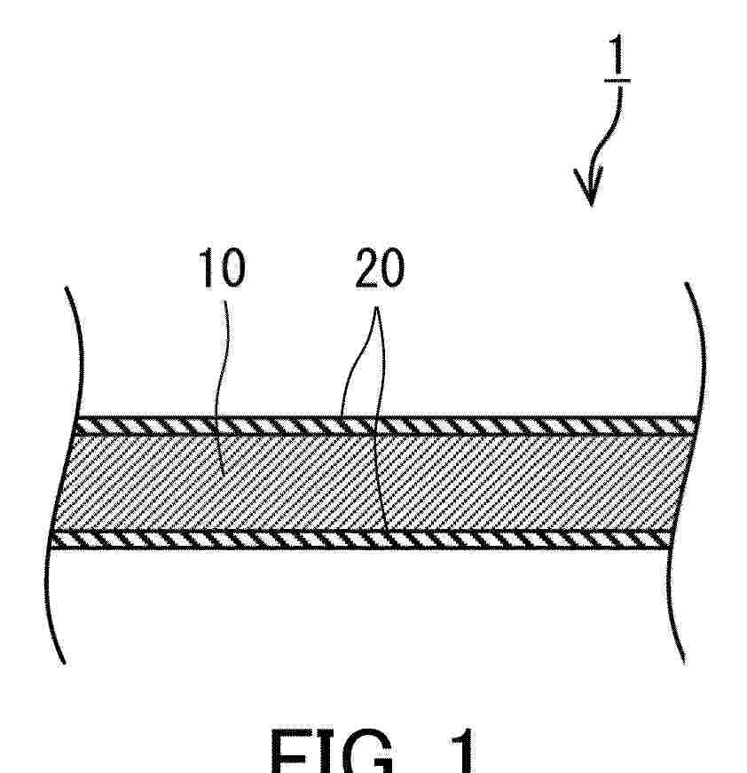
0001 A water electrolysis electrode 1 includes an electroconductive substrate 10 and a layered double hydroxide layer 20. The layered double hydroxide layer is disposed on a surface of the electroconductive substrate 10. An extinction coefficient k<800> of the layered double hydroxide layer 20 at an wavelength of 800 nm is 0.08 or more.
Resumen de: EP4733442A1
A water electrolysis electrode 1 includes a conductive substrate 11 and a layered double hydroxide layer 12. The layered double hydroxide layer 12 is disposed on a surface of the conductive substrate 11. The layered double hydroxide layer 12 includes two or more transition metals. The layered double hydroxide layer 12 includes a chelating agent.
Resumen de: EP4733444A1
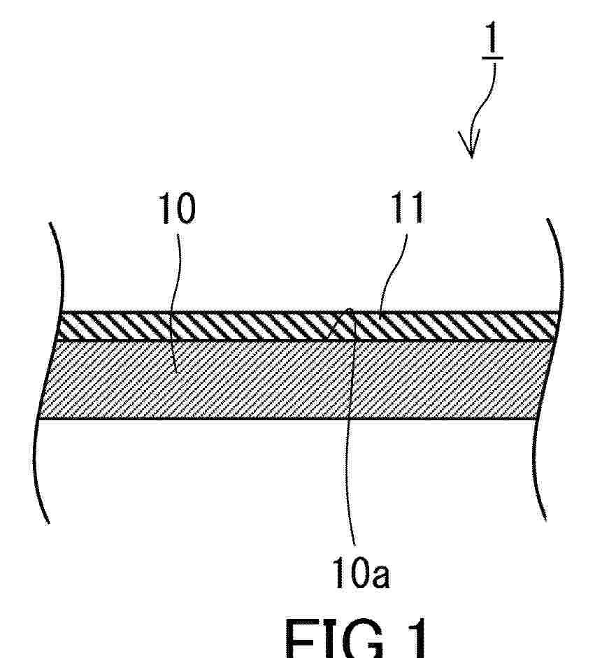
A water electrolysis electrode 1 includes a conductive substrate 10 and a layered double hydroxide layer 11. The conductive substrate 10 has a surface 10a including nickel having a (111) plane orientation. The layered double hydroxide layer 11 includes a layered double hydroxide including two or more transition metals. The layered double hydroxide layer 11 is disposed on the surface 10a.
Resumen de: EP4733439A1
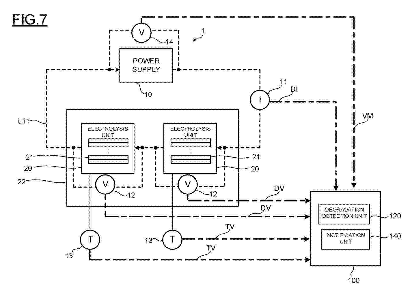
0001 A power supply unit supplies a current of a second current value different from a first current value to an electrolysis unit at a first time point from a state of supplying a current of the first current value to the electrolysis unit, and then returns to the state of supplying the current of the first current value at a second time point. A degradation detection unit finds a difference value between a first measured voltage of the electrolysis unit acquired when the current of the first current value is supplied before the first time point and a second measured voltage of the electrolysis unit acquired when the current of the first current value is switched to the current of the second current value at the first time point, and detects the degradation of the electrolysis unit according to the electrolysis unit voltage difference value.
Resumen de: EP4734317A1
The present invention relates to a method (1000-2000) of controlling an electric energy generation plant (1). The plant comprises a unit for generating electric energy from a renewable energy source (2), an electrolyzer (51) for the generation of hydrogen, a battery (8) connected to the electrolyzer (51), at least one converter (3,4) adapted to supply an available power generated by the electric energy generation unit (2) to at least one of a load and the electrolyzer (51), a control system (6) for controlling the plant (1), and input means (7). The input means are adapted to acquire at least one of input information relating to the operation of the plant (1), meteorological information of a region in which the plant (1) is located and information relating to the operation of further plants located in the vicinity of the plant (1).The method comprises that the control system performs the step of: monitoring (1002) the available power, generated by the renewable energy source (2), andwhen the available power falls below a threshold (1011), the method comprises that the control system performs the step of:estimating (1014-1017) a recovery time interval at the end of which the available power will exceed the threshold,determining (1014-1017) whether the battery is able to supply the electrolyzer (51) for said recovery time interval, and in the affirmative case, supplying (1012) the electrolyzer (51) by means of the battery (8).In particular, the step of estimating a recovery tim
Resumen de: EP4733249A2
A method of treating an at least partially unconsumed hydrogen generator cartridge including water and a metal hydride includes treating the at least partially unconsumed hydrogen generator cartridge to form a treated hydrogen generator cartridge. When subjected to testing conditions the treated hydrogen generator cartridge produces no hydrogen gas or produces hydrogen gas at a lower rate than the at least partially unconsumed hydrogen generator cartridge subjected to the testing conditions. The testing conditions include heating at less than or equal to 300 °C, agitation, exposing the metal hydride to a protic solvent, or a combination thereof.
Resumen de: EP4733445A1
The present invention discloses a hierarchical porous nickel electrode and a method for preparing the same. The method includes: spraying a nickel-aluminum material on a nickel substrate to prepare a nickel-aluminum coating on the surface of the nickel substrate, to obtain a first intermediate product, the first intermediate product including the nickel substrate and the nickel-aluminum coating; heat-treating the first intermediate product, to obtain a second intermediate product; placing the second intermediate product into alkaline solutions of different concentrations for stepwise activation sequentially, to obtain a hierarchical porous nickel electrode. In the stepwise activation, the concentrations of the alkaline solution are gradually decreased, and activation temperatures are gradually decreased. The hierarchical porous nickel electrode of this invention ensures high mass transfer rates and catalytic efficiency. The coating has strong bonding strength with the substrate, stable interlayer structure, good mechanical properties, stability, and long service life.
Resumen de: EP4734318A1
A hybrid power plant includes a nuclear source generator assembly (2), configured to provide a primary electric power (WEP) from a nuclear source; an electrolyzer (3) operable to produce a first mixture (M1) containing hydrogen and a second mixture (M2) containing oxygen from a water flow (FW); a hydrogen storage system (5), coupled to the electrolyzer (3) to receive hydrogen from the first mixture (M1); an oxygen storage system (6), coupled to the electrolyzer (3) to receive oxygen from the second mixture (M2); and a hydrogen generator assembly (7), operable to produce a secondary electric power (WES) using the hydrogen from the hydrogen storage system (5) and the oxygen from the oxygen storage system (6). A power divider (8), coupled to a distribution grid (15) and to the electrolyzer (3), is configured to controllably divide the primary electric power (WEP) between the distribution grid (15) and the electrolyzer (3).
Resumen de: EP4733449A1
0001 A water electrolysis electrode 1 includes an electroconductive substrate 10 and a layered double hydroxide layer 20. The electroconductive substrate 10 includes Ni. The layered double hydroxide layer 20 is disposed on a surface of the electroconductive substrate 10. The layered double hydroxide layer 20 includes Ni. In a XRD pattern of grazing incidence X-ray diffraction for the water electrolysis electrode 1, a ratio P<003>/P<111> of a diffraction peak intensity P<003> of a (003) plane of a layered double hydroxide to a diffraction peak intensity P<111> of a (111) plane of Ni is 0.025 or less.
Resumen de: WO2024218273A1
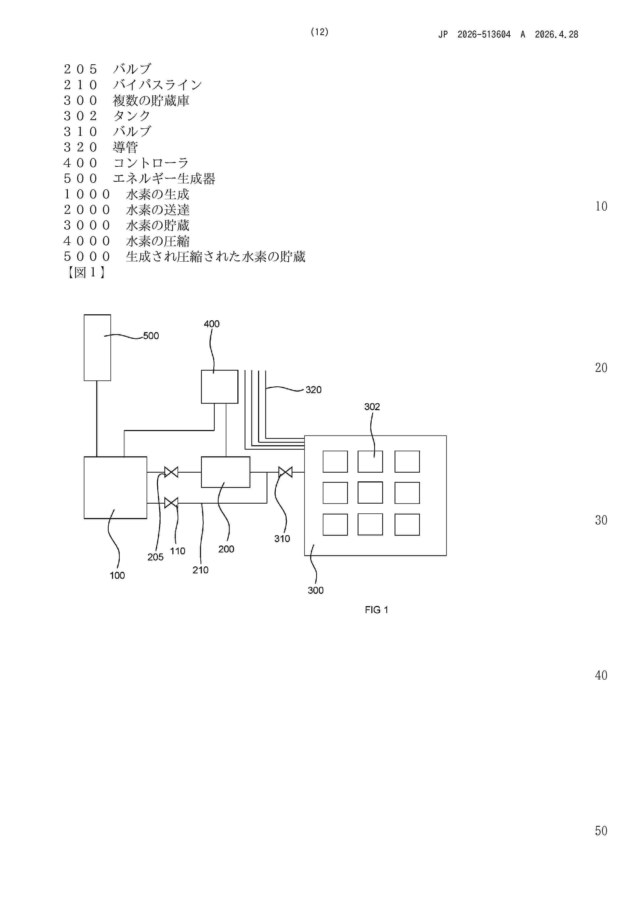
A method for storing hydrogen in a plurality of subsea storages in a system. The system comprising an electrolyser source (100) for producing hydrogen at a source pressure; a downstream compressor (200) for compressing the hydrogen from the source pressure to a compressed higher pressure; and a plurality of storages (300) each for storing compressed hydrogen at the compressed higher pressure and each being subsea. The method comprising at least the steps of: producing hydrogen (1000) by the electrolyser source (100) at the source pressure; passing the hydrogen (2000) to the plurality of storages (300) through a bypass line (210) around the compressor (200); and storing the hydrogen (3000) in at least one of the plurality of storages (300) at a first pressure below the compressed higher pressure. A system for storing hydrogen in a plurality of subsea storages, the system comprising: an electrolyser source (100) for producing hydrogen at a source pressure; a downstream compressor (200) for compressing the hydrogen from the source pressure to a compressed higher pressure; a plurality of storages (300) each for storing compressed hydrogen at the compressed higher pressure and each being subsea; and a controller (400) for controlling the electrolyser source (100), the downstream compressor (200), and valves (310) to the plurality of storages (300). The controller (400) is configured for controlling the system in, at least, two alternative ways: A) passing the hydrogen, produced by
Resumen de: WO2024189288A1
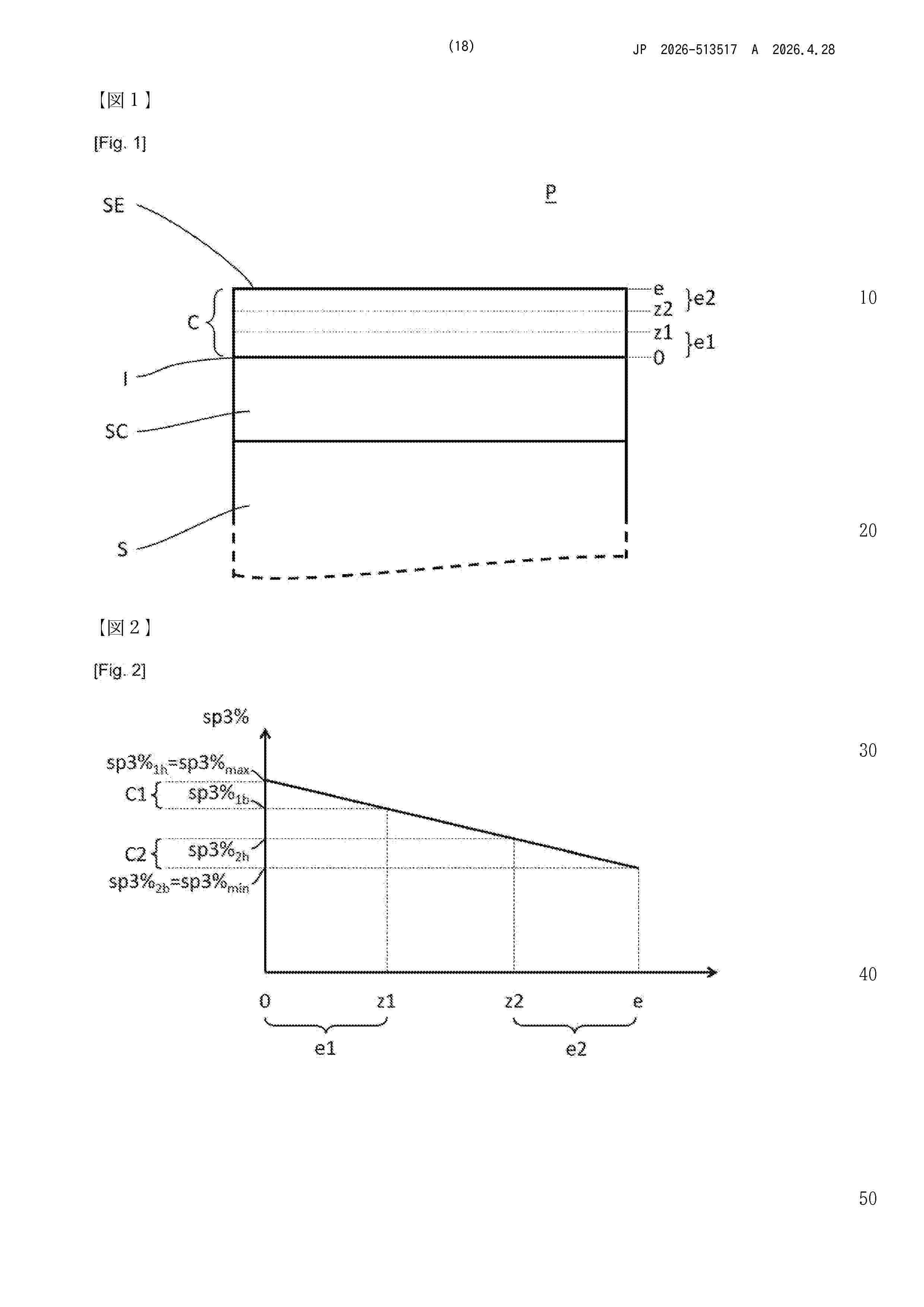
The invention relates to a part comprising a metal substrate and a layer of material based on amorphous carbon having sp2 hybridised bonds and sp3 hybridised bonds, wherein the layer has: - a first content of sp3 hybridised bonds on the substrate side; and - a second content of sp3 hybridised bonds on the side of an outer surface of the layer; - the first content being greater than the second content, characterised in that an average content within the layer of sp3 hybridised bonds is between 5% and 65%, and preferably between 5% and 45%, and in that the content of sp3 hybridised bonds changes continuously within the layer.
Resumen de: EP4733440A1
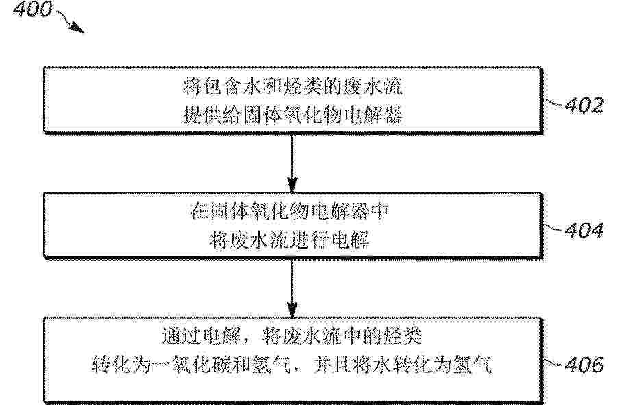
Systems and methods for wastewater utilization are described herein. In some approaches, the system (100) comprises a solid oxide electrolyzer (104) and a syngas upgrading unit (112). The solid oxide electrolyzer (104) comprises a first electrode (128), a second electrode (130) and an electrolyte (132). The syngas upgrading unit (112) receives at least a portion of a product stream (110) from the solid oxide electrolyzer (104) and generates a wastewater stream (102) comprising water and a hydrocarbon species. A recycle line (120) recycles the wastewater stream (102) from the syngas upgrading unit (112) to the first electrode (128) of the solid oxide electrolyzer (104). In some embodiments, the system (100) comprises a carbon dioxide supply (108) to co-feed carbon dioxide to the solid oxide electrolier (104) with the wastewater stream (102). In some embodiments, the system (100) comprises a separation unit (114) that separates the wastewater stream (102) from a product stream (110) of the syngas upgrading unit (112).
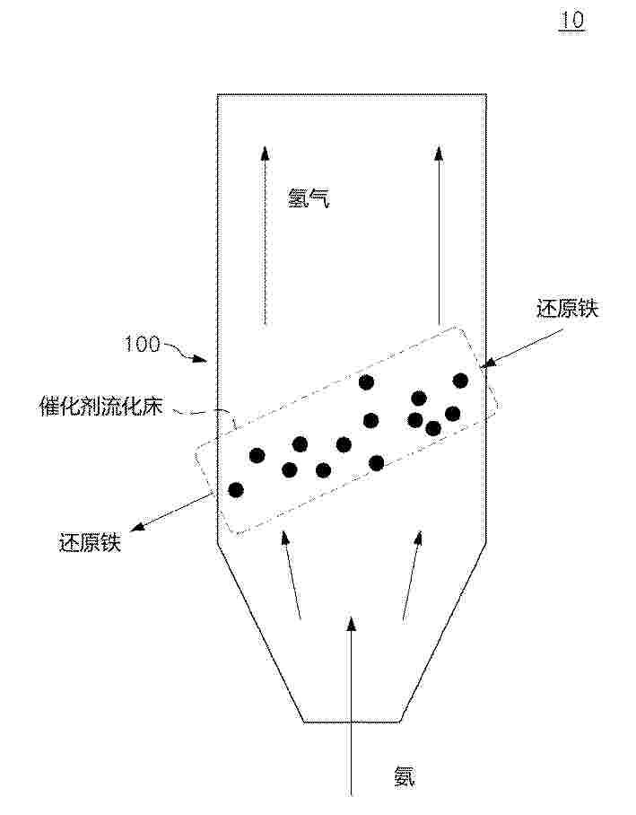
Resumen de: WO2025127502A1
Provided according to exemplary embodiments of the present invention is an ammonia decomposition system capable of minimizing the generation of iron nitride, which is a by-product.
Nº publicación: CN121941802A 28/04/2026
Solicitante:
博泰克斯氢能有限公司
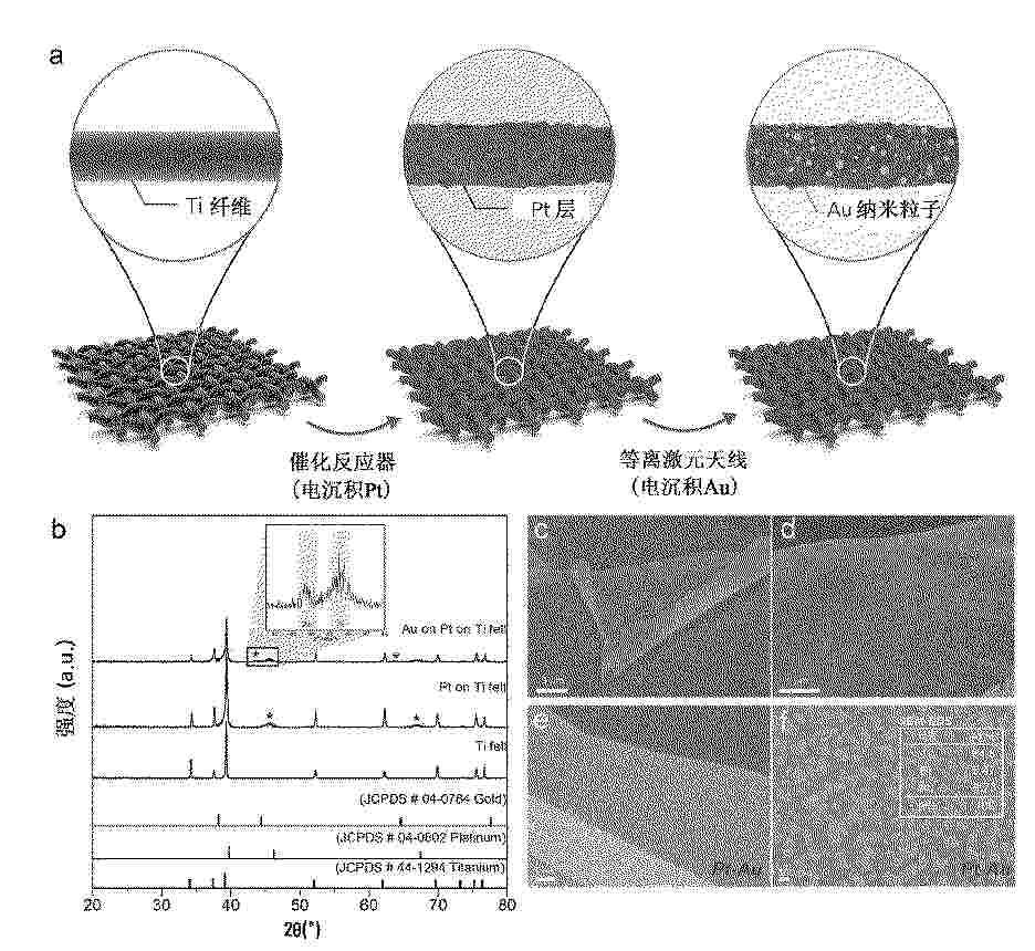
Resumen de: WO2025058457A1
The present application relates to a hybrid electrode comprising plasmonic nanoparticles and an electrolytic system comprising same. The hybrid electrode and the electrolytic system comprising same according to embodiments of the present application may reactivate a catalyst surface by utilizing a plasmonic phenomenon during an electrochemical reaction using a plasmonic-active electrode (antenna-reactor) composite electrode.
 BOPI
BOPI
 Sede Electrónica