Si deseas distinguir tus productos, servicios o ambos de los de otra empresa, es posible que necesites una marca o nombre comercial. Descubre qué son, en qué consiste su procedimiento de registro y qué implica.

Información sobre los plazos de presentación de solicitudes de transformación de marcas de la Unión Europea en marca nacional española. Más información


Si tienes un nuevo dispositivo, producto o procedimiento que resuelva un problema técnico o tenga una ventaja práctica, existen distintas formas de protegerlo en España y en otros países. Descubre cómo hacerlo.

¿Tu innovación reside en la estética, la ornamentación o la apariencia de tu producto? Protégela mediante un diseño industrial. Descubre qué derechos confiere el registro y cómo realizar la tramitación.

Las indicaciones geográficas protegen el nombre de un producto originario de una zona geográfica, a la cual le debe una determinada calidad, reputación u otra característica. Descubre qué son, en qué consiste su procedimiento de registro y qué beneficios conceden.

Las patentes publicadas en todo el mundo son una valiosa fuente de información científica, técnica y comercial.

Si eres emprendedor/a o una empresa y quieres potenciar y mejorar la rentabilidad de tu negocio protegiendo de forma adecuada los activos intangibles de tu organización, en este espacio encontrarás lo necesario.


 782
resultados
782
resultados
 Última actualización
28/04/2026 [07:05:00]
Última actualización
28/04/2026 [07:05:00]


Resumen de: WO2024200817A1
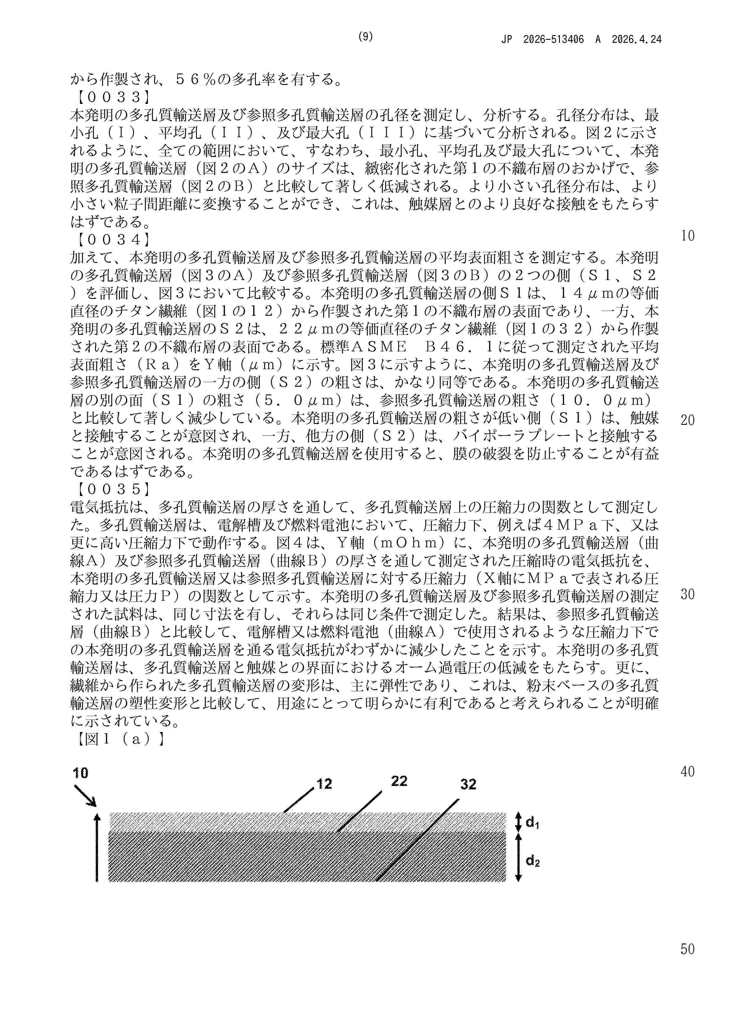
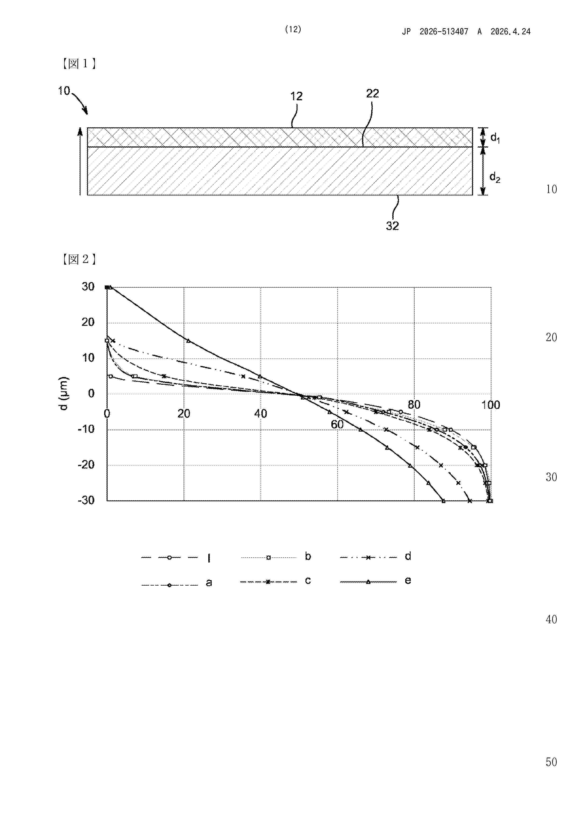
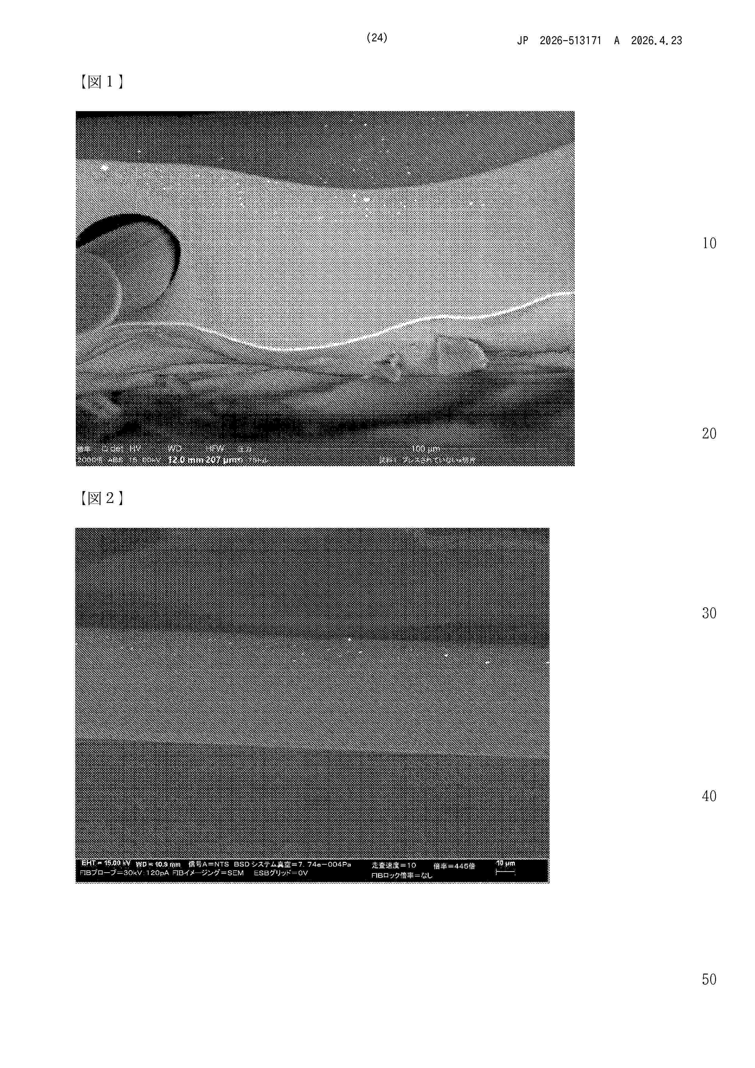
The invention provides a porous transport layer for an electrolyser or for a fuel cell, comprising - a first nonwoven layer of metal fibers provided for contacting a proton exchange membrane, wherein the first nonwoven layer of metal fibers comprises metal fibers of a first equivalent diameter, wherein the first nonwoven layer of metal fibers has a first surface roughness and a first porosity, - a second nonwoven layer of metal fibers, wherein the second nonwoven layer of metal fibers comprises metal fibers of a second equivalent diameter, wherein the second nonwoven layer of metal fibers has a second surface roughness and a second porosity, wherein the first surface roughness is below 10 µm, the first equivalent diameter is smaller than the second equivalent diameter, the first surface roughness is smaller than the second surface roughness for at least 20%, e.g., in a range of 20% to 120%, wherein the first porosity is smaller than the second porosity for at least 10%, e.g., in a range of 10% - 50%, and wherein the first nonwoven layer is metallurgically bonded to the second nonwoven layer.

Resumen de: WO2024200810A1
Porous transport layer for an electrolyser or for a fuel cell, comprising - a first nonwoven layer of metal fibers provided for contacting a proton exchange membrane, wherein the first nonwoven layer of metal fibers comprises metal fibers of a first equivalent diameter, wherein the first nonwoven layer of metal fibers has a first surface roughness and a first porosity, - a second nonwoven layer of metal fibers, wherein the second nonwoven layer of metal fibers comprises metal fibers of a second equivalent diameter, wherein the second nonwoven layer of metal fibers has a second surface roughness and a second porosity, wherein the first surface has a material ratio of less than 5 % of material at a height of 5 µm, and more than 70% of material at a depth of -5 µm, the first equivalent diameter is smaller than the second equivalent diameter, the first surface roughness is smaller than the second surface roughness for at least 20%, e.g., in a range of 20% to 120%, the first porosity is smaller than the second porosity for at least 10%, e.g., in a range of 10% to 50%, and wherein the first nonwoven layer is metallurgically bonded to the second nonwoven layer.
Resumen de: AU2024336445A1
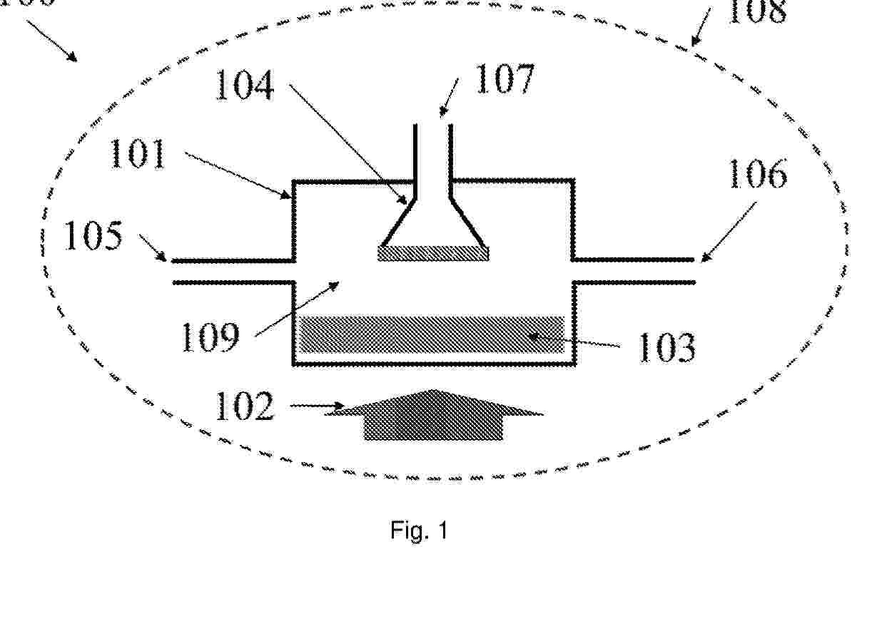
The present invention relates to a method for obtaining hydrogen through water molecule dissociation using thermochemical reactions under (quasi-)isothermal conditions, which comprises the following steps: placing active material (103) in the reaction chamber (109) of a reactor (101); reducing the active material (103) by supplying heat; evacuating the oxygen produced through a first outlet (106); injecting water into the reaction chamber (109); oxidising the active material (103), thereby producing hydrogen; filtering the hydrogen produced through a selective filter (104) during the oxidisation of the active material (103); and evacuating the filtered hydrogen through a second outlet (107), thereby obtaining a flow of high-purity hydrogen. The invention also relates to a device for carrying out the method.
Resumen de: WO2026083621A1
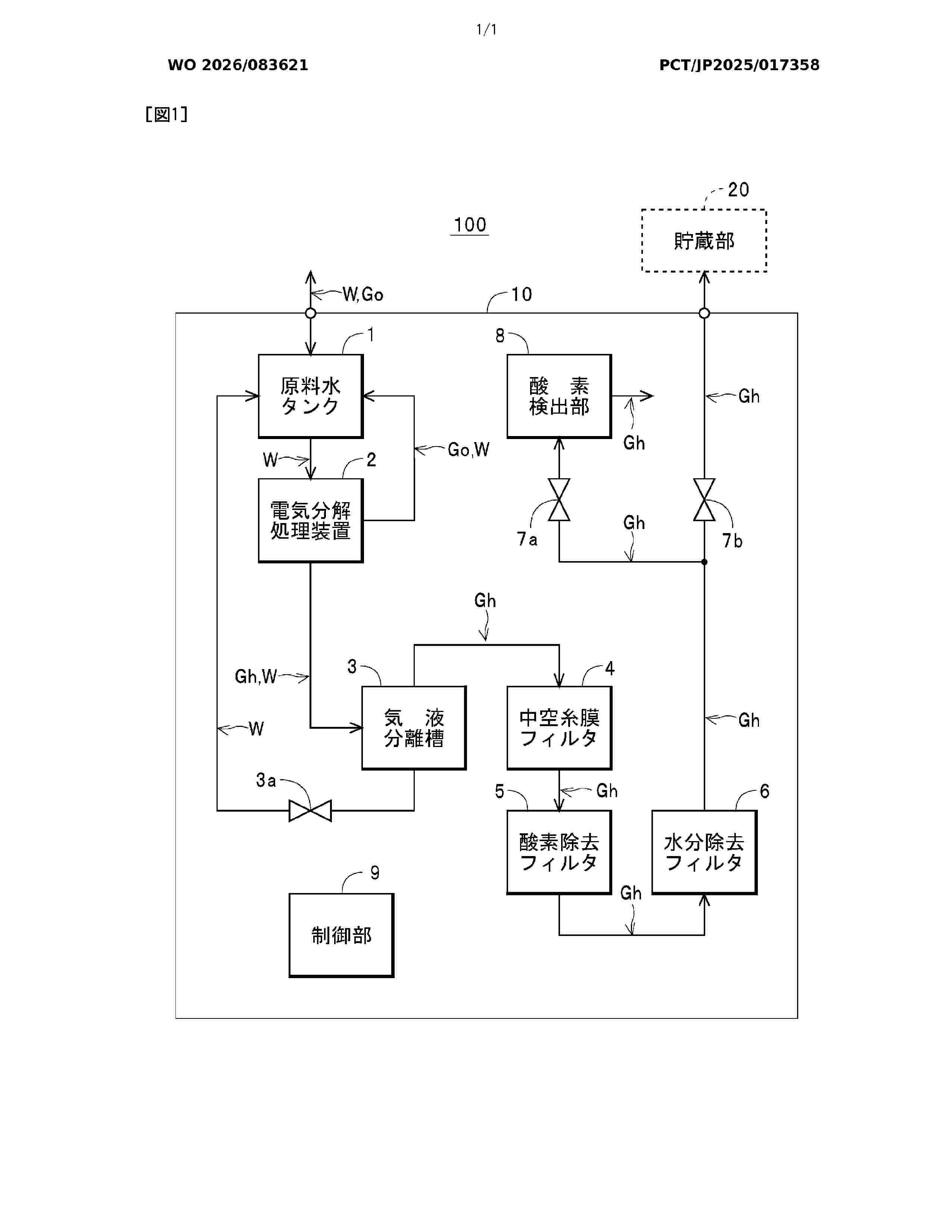
The present invention makes it possible to supply hydrogen gas from which impurities such as moisture and oxygen are suitably removed to a supply object that requires highly pure hydrogen gas. The present invention is provided with solenoid valves 7a, 7b which adjust the detection position of oxygen by an oxygen detection unit 8 and the flow rate of hydrogen gas Gh to a storage unit 20 in accordance with the control of a control unit 9, and is configured such that "a removal unit (a gas-liquid separation tank 3, a hollow fiber membrane filter 4, an oxygen removal filter 5, and a moisture removal filter 6)" and the oxygen detection unit 8 are housed in a housing 10, and the hydrogen gas Gh passed through the detection position is discharged into the housing 10. The hollow fiber membrane filter 4 is disposed so that the moisture separated from the hydrogen gas Gh can be discharged into the housing 10. When the hydrogen purity of the hydrogen gas Gh specified on the basis of the detection result by the oxygen detection unit 8 reaches a predetermined allowable purity for supply, the control unit 9 controls the solenoid valves 7a, 7b to supply the high purity hydrogen gas Gh to the storage unit 20.
Resumen de: AU2024412535A1
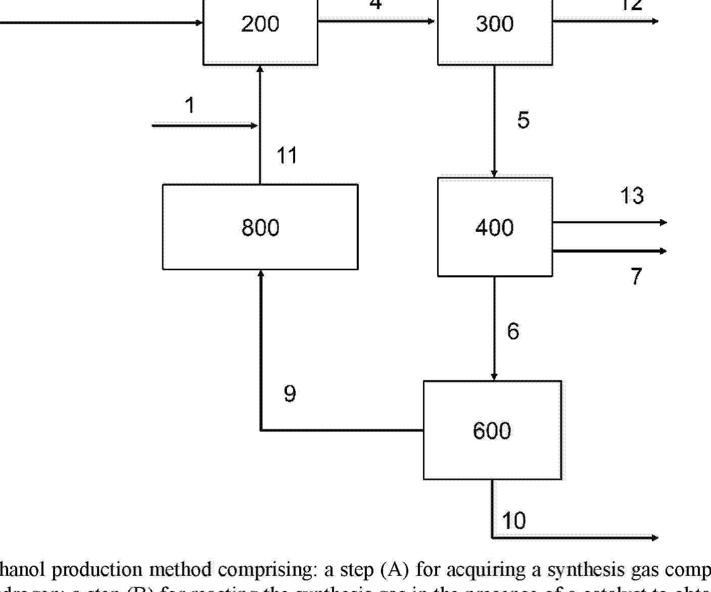
A methanol production method comprising: a step (A) for acquiring a synthesis gas comprising at least carbon dioxide and hydrogen; a step (B) for reacting the synthesis gas in the presence of a catalyst to obtain a methanol mixture; a step (C) for distilling the methanol mixture to separate out each of methanol, a distillation waste liquid, and distillation wastewater; and a step (D) for subjecting the distillation waste liquid and/or the distillation wastewater to an organic matter decomposition treatment to obtain a decomposition gas and treated water.
Resumen de: US20260110234A1
Embodiments of the invention relate to producing hydrogen from a subsurface formation by injecting a reactant into the subsurface formation and reacting the reactant with the subsurface formation to form at least one of hydrogen gas or a mineralized product within the subsurface formation. The hydrogen produced is collected or one or more components of the reactant is sequestered to form a mineralized product in the subsurface formation. Other embodiments of the invention relate to producing hydrogen by injecting a thermal fluid into the subsurface rock formation, where the thermal fluid includes a reactant. The reactant is reacted with components in the subsurface formation to form at least one of hydrogen gas mineralized sulfur, or mineralized carbon.
Resumen de: WO2026081643A1
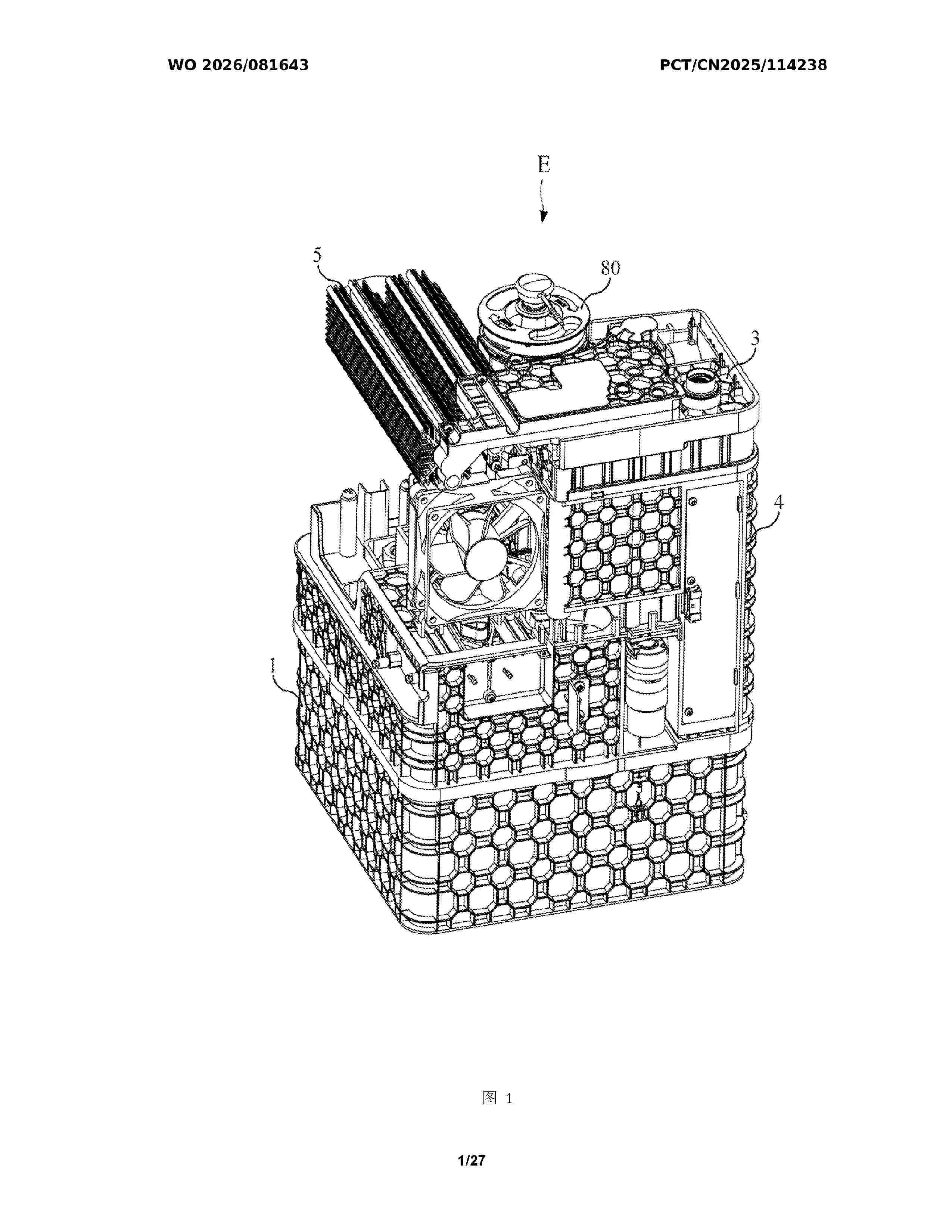
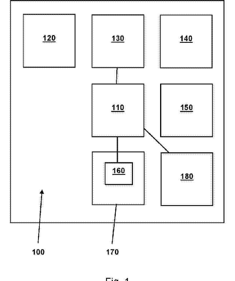
A hydrogen generator having a condensate water collection function, comprising a water tank, an electrolytic tank, a condensing and filtering device, a humidifier, and an integrated flow channel device, wherein the water tank comprises an accommodating space for accommodating electrolytic water; the electrolytic tank receives the electrolytic water to generate and output a hydrogen-containing gas; the condensing and filtering device is coupled to the electrolytic tank to condense and filter the hydrogen-containing gas; the humidifier comprises a water collection chamber and a humidification chamber isolated from each other; the water collection chamber is used for collecting condensate water generated from the hydrogen-containing gas after condensation, and the humidification chamber is used for accommodating make-up water and receiving the hydrogen-containing gas into the make-up water; and the integrated flow channel device is coupled to the water tank, the electrolytic tank, the condensing and filtering device, and the humidifier, so that the make-up water in the humidification chamber can be supplemented from the humidification chamber, the water collection chamber, and the condensing and filtering device into the water tank.
Resumen de: WO2026082793A1
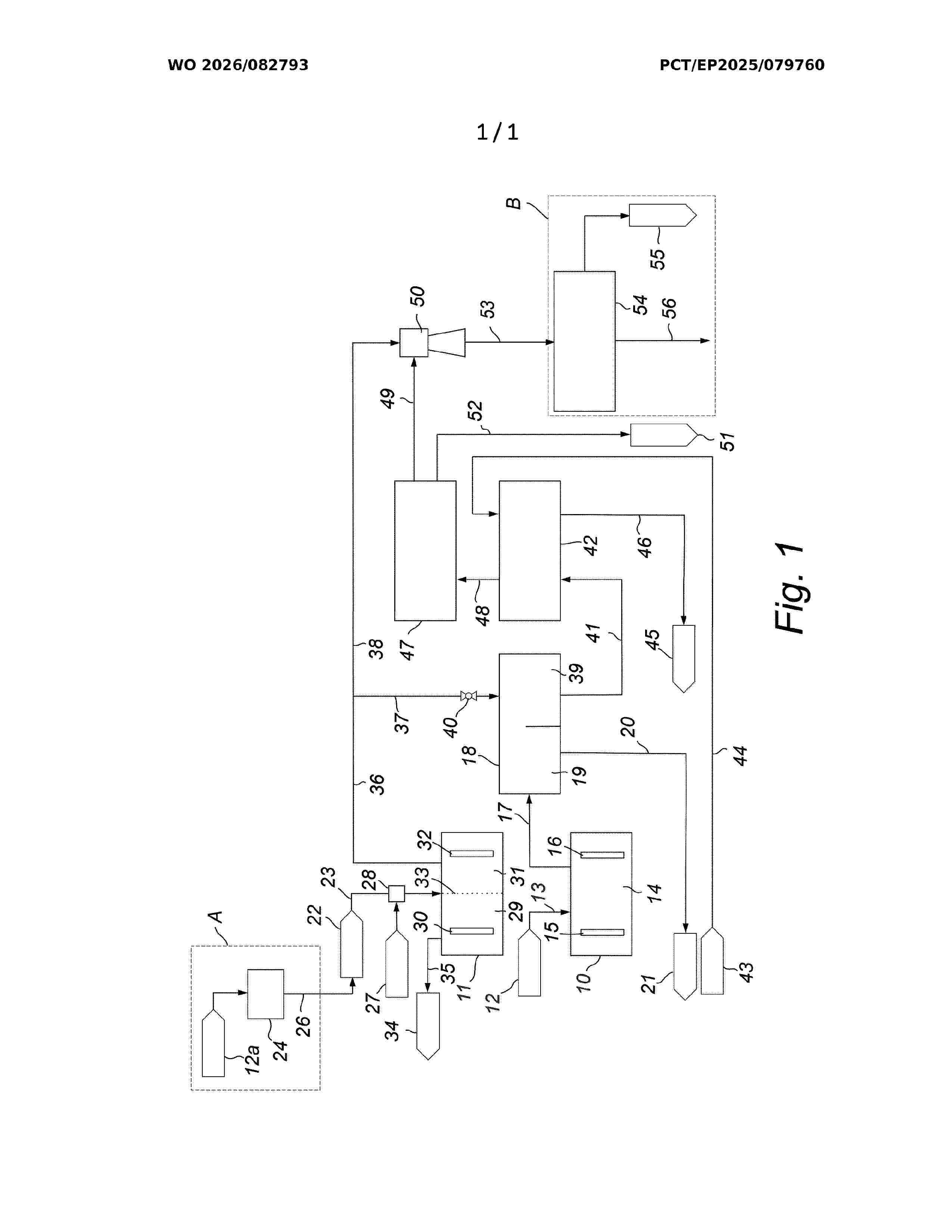
The invention relates to a method and plant for producing hydrogen comprising an electrochlorination unit (10) and a water electrolysis unit (11). In the electrochlorination unit (10), seawater (12) or brine is electrolyzed to produce a liquid hypochlorite stream and an oxygen-polluted hydrogen gas stream. The hydrogen gas is separated from the liquid phase in a degasser vessel (18). High-purity hydrogen produced in the water electrolysis unit (11) from demineralized water (22) is divided into two portions, one portion (37) being mixed with the oxygen-polluted hydrogen in the degasser vessel (18) to form a non-flammable mixed gas, and the other portion (38) being supplied to an ejector (50) for compressing and further concentrating the mixed hydrogen. Optionally, residual oxygen is removed in a DE-OXO unit (54). The invention enables recovery and utilization of hydrogen from electrochlorination processes while improving overall hydrogen yield and safety.
Resumen de: WO2026082452A1
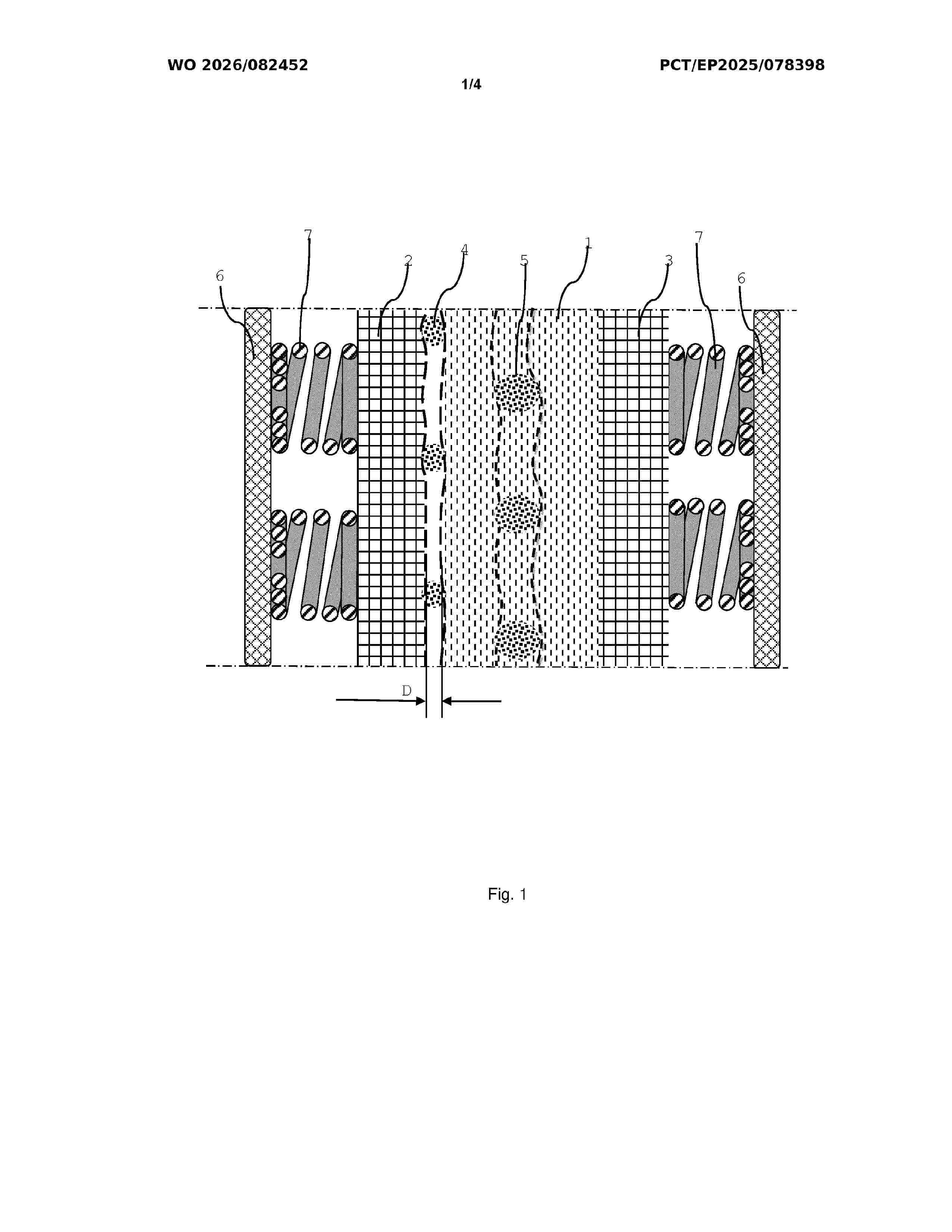
An electrolyser cell comprises a diaphragm which partitions the cell into a cathode chamber and an anode chamber and wherein an oxygen evolving anode electrode arranged at the anode chamber side of the diaphragm and a hydrogen evolving cathode electrode arranged at the cathode chamber side of the diaphragm is provided. A spacer is provided between the cathode electrode and the diaphragm, and/or between the anode electrode and the diaphragm which spacer is adapted to ensure contact between electrolyte fluid elements in the cathode and/or in the anode chamber and the diaphragm, and adapted to ensure a pre-determined non-zero distance D between the cathode electrode and/or the anode electrode and the diaphragm.
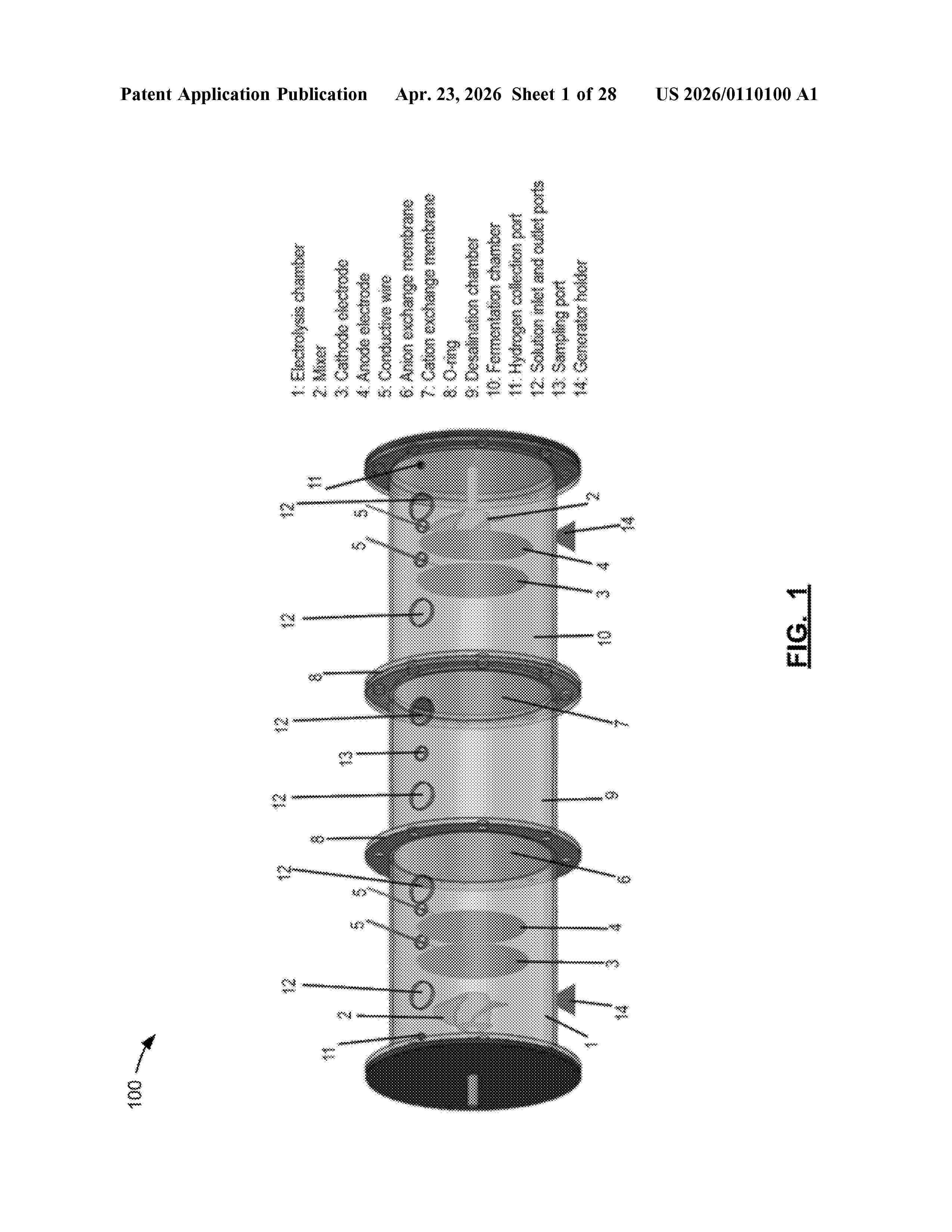
Resumen de: US20260110100A1
0000 Provided are systems and methods for multi-process generators employing fermentation, desalination, and electrolysis technologies. The generator system includes a fermentation compartment configured to receive a mixture of biomass waste and an anaerobic microorganism solution comprising bacteria for bioenergy production; an electrolysis compartment configured to receive an electrolyte solution comprising a saline mixture, the electrolysis compartment including first and second spaced apart electrodes at least partially submerged in the electrolyte solution; and a desalination compartment positioned between the fermentation compartment and the electrolysis compartment, the desalination compartment configured to receive a saline solution and comprising an anion exchange membrane separating the desalination compartment from the electrolysis compartment and a cation exchange membrane separating the desalination compartment from the fermentation compartment, wherein the desalination compartment is configured to perform ion exchange processes to produce freshwater.
Resumen de: WO2024206331A1
The present invention relates to a composition comprising about 90% to about 99.99% by weight of one or more non-crosslinked fluorinated sulfonyl fluoride polymers and about 0.01% to about 10% by weight of one or more precious metal catalyst, based on the total weight of the composition, where the one or more precious metal catalyst is uniformly distributed throughout the one or more non-crosslinked fluorinated sulfonyl fluoride polymer. Such a composition may be formed, for example by extrusion, into a cation exchange precursor and, after treatment, a cation exchange membrane. The resulting films and membranes have precious metal catalyst uniformly distributed throughout the layer of catalyst-containing polymer.
Resumen de: WO2024088907A2
The present invention relates to stack module with at least one Solid Oxide electrolysis stack that comprises a plurality of stacked Solid Oxide electrolysis cells, wherein the stack module comprises two gas inlet connections and two gas outlet connections. According to the invention, the at least one Solid Oxide electrolysis stack is encapsulated in a metal container, wherein the two gas inlet connections and the two gas outlet connections are attached to the metal container. The invention further relates to Solid Oxide Electrolyzer with at least one stack module and a method of exchanging a stack module of a Solid Oxide Electrolyzer.
Resumen de: EP4729656A1
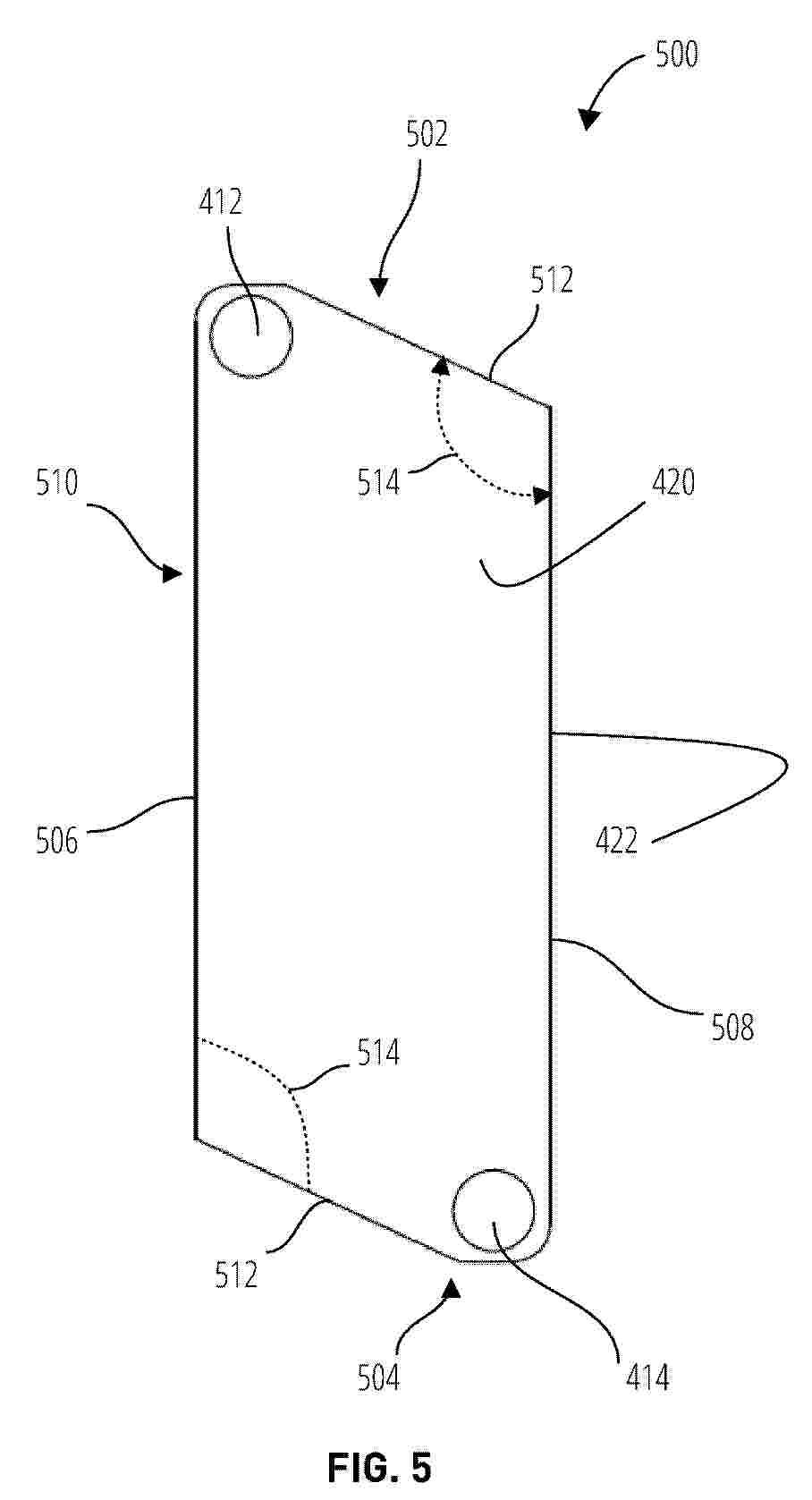
0001 A bipolar plate is provided that includes an inlet side, an outlet side opposite of the inlet side, a first side extending from the inlet side to the outlet side, and a second side parallel to the first side and extending from the inlet side to the outlet side. A perimeter is defined by the outer edges of the bipolar plate and an area is defined within the second perimeter. The perimeter is selected to reduce material in the bipolar plate. An electrolyzer stack is also provided.
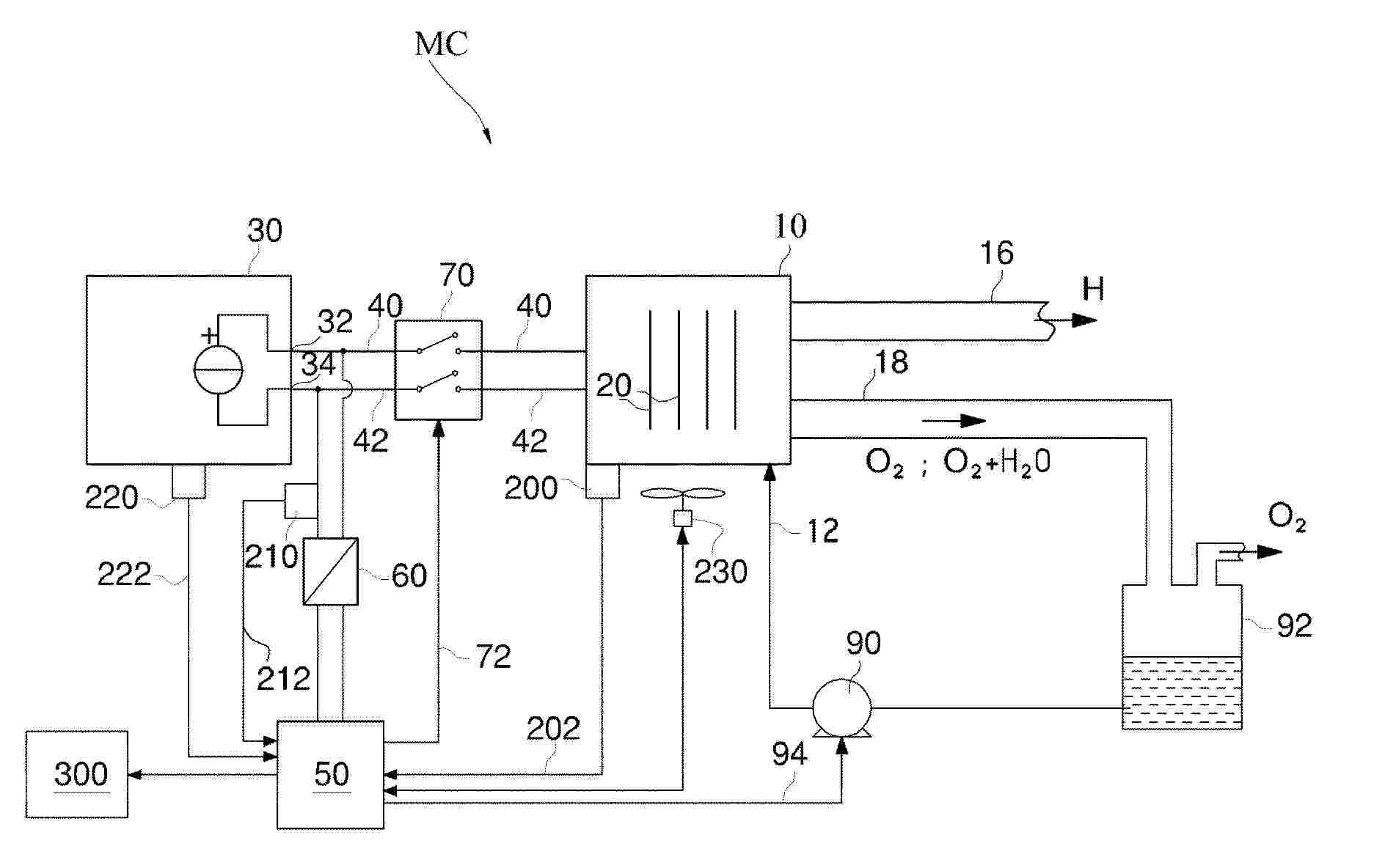
Resumen de: WO2025029154A1
The present invention relates to a system and method for generating and providing hydrogen to a combustion engine, and for controlling the generation and provision of hydrogen to a combustion engine; comprising a combustion engine; an electrolysis cell for converting water into hydrogen gas and oxygen gas, wherein the electrolysis cell is at least fluidly connected to the combustion engine; an electronic process control system is operatively connected to the electrolysis cell to control the generation of hydrogen gas and delivery of hydrogen gas to the combustion engine; and an enclosure comprising an explosion protection system and/or walls of glass fibre or carbon fibre reinforced thermosetting polymer or metallic material, and wherein the enclosure comprises at least part of the electronic process control system.
Resumen de: EP4729490A1
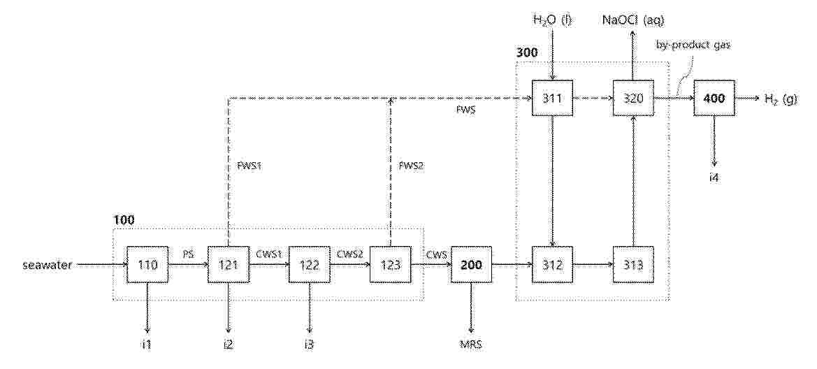
0001 One aspect of the present invention provides a system for manufacturing sodium hypochlorite and hydrogen gas, comprising: a desalination module generating a fresh water stream and a concentrated water stream by desalinating seawater; a crystallization module generating a solid raw material including sodium chloride by crystallizing the concentrated water stream; an electrolysis module generating sodium hypochlorite and by-product gas by electrolyzing reactants derived from the solid raw material and water; and a gas purification module generating hydrogen gas by purifying the by-product gas.
Resumen de: AU2024257970A1
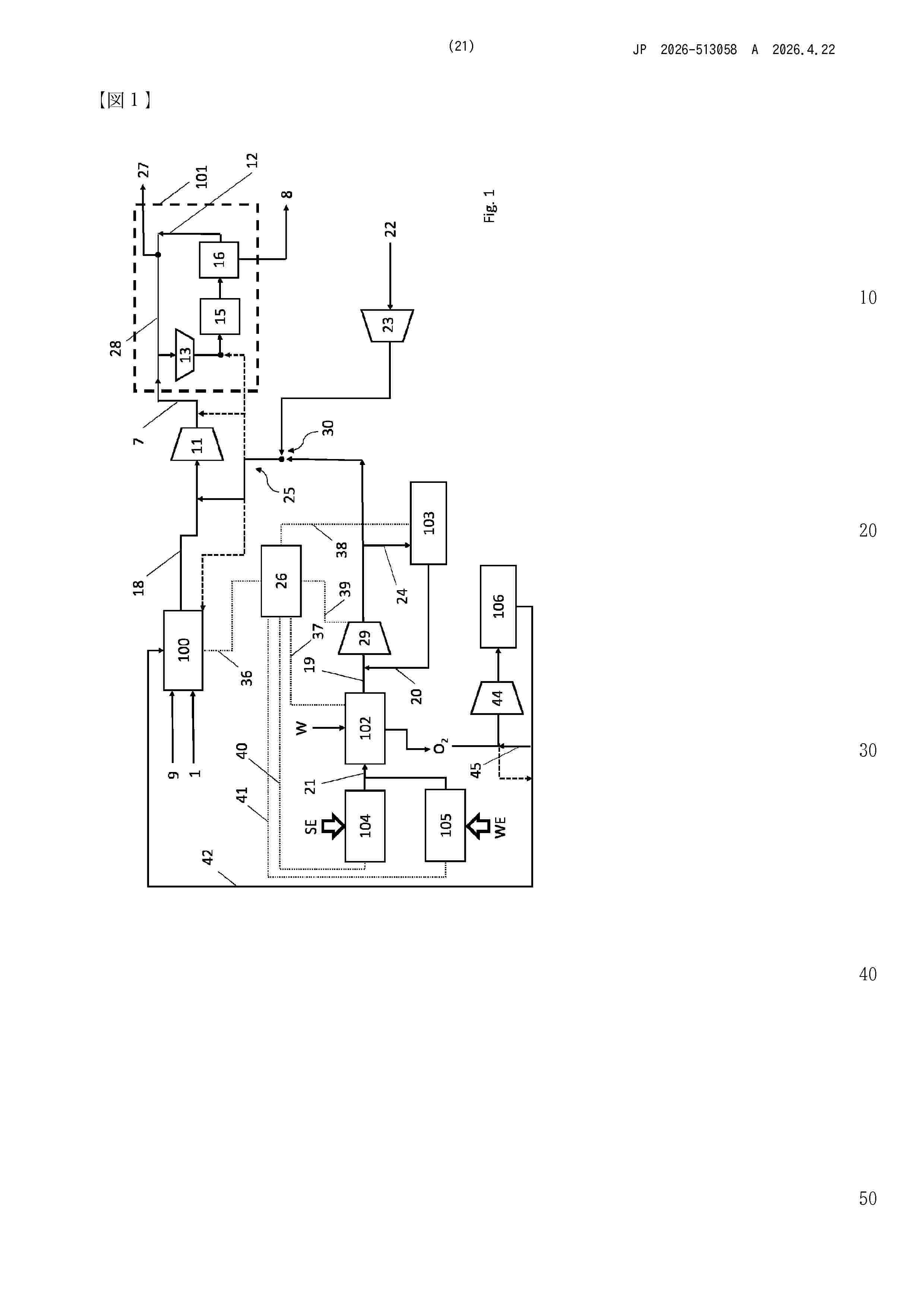
Process for synthesis of ammonia wherein: ammonia make-up gas (7) containing hydrogen and nitrogen is reacted in an ammonia converter (15) under ammonia forming conditions thus obtaining an ammonia-containing effluent (8); a first hydrogen portion contained in the ammonia make-up gas (7) is produced by reforming a hydrocarbon source (1) in a reforming process (100); a second hydrogen portion (19) contained in the ammonia make-up gas (7) is produced separately from said reforming process (100), by using at least a renewable energy source (SE, WE); a part of said hydrogen (19) produced in step (c) is stored in a hydrogen storage (103); hydrogen (20) from said hydrogen storage (103) is used to fully or partially replace said second hydrogen portion (19) when said renewable energy source (SE, WE) is fully or partially unavailable. Said process comprising the steps of: assessing an expected flow rate of the hydrogen (19) produced in step (c); adjusting a flow rate of the hydrocarbon source (1) so that a flow rate of the first hydrogen portion in said ammonia make- up gas (7) is in a desired ratio with respect to said expected flow rate; detecting an actual amount, e.g., a filling level, of said hydrogen in said hydrogen storage (103); detecting an actual flow rate of hydrogen produced using the renewable energy source (SE, WE), and adjusting a flow rate of the hydrogen (20) from said hydrogen storage (103) depending on said actual amount detected in said hydrogen storage (103) and
Resumen de: EP4446467A1
0001 The present invention relates to an electrochemical electrode structure comprising at least one electrode element and a supportive element. Each electrode element is a two-dimensionally extended electrically conductive element with an open structure and has a first edge portion. The supportive element has a resilient region extending areally in a plane of the main extension of the resilient region. The resilient region is adapted to push the at least one electrode member away from the supportive element in a direction at least substantially perpendicular to the plane of the main extension of the resilient region. The supportive element has a first tongue region arranged at an edge of the supportive element. The first edge portion of the at least one electrode element is bent around the first tongue region of the supportive element thereby attaching the at least one electrode element to the supportive element. Moreover, the invention relates to an electrochemical cell and to a bipolar electrode assembly each comprising such an electrode element, to an electrochemical cell arrangement with a plurality of such bipolar electrode assemblies, as well as to a method of attaching an electrode element to a supportive element of such an electrochemical electrode structure.
Resumen de: EP4446466A1
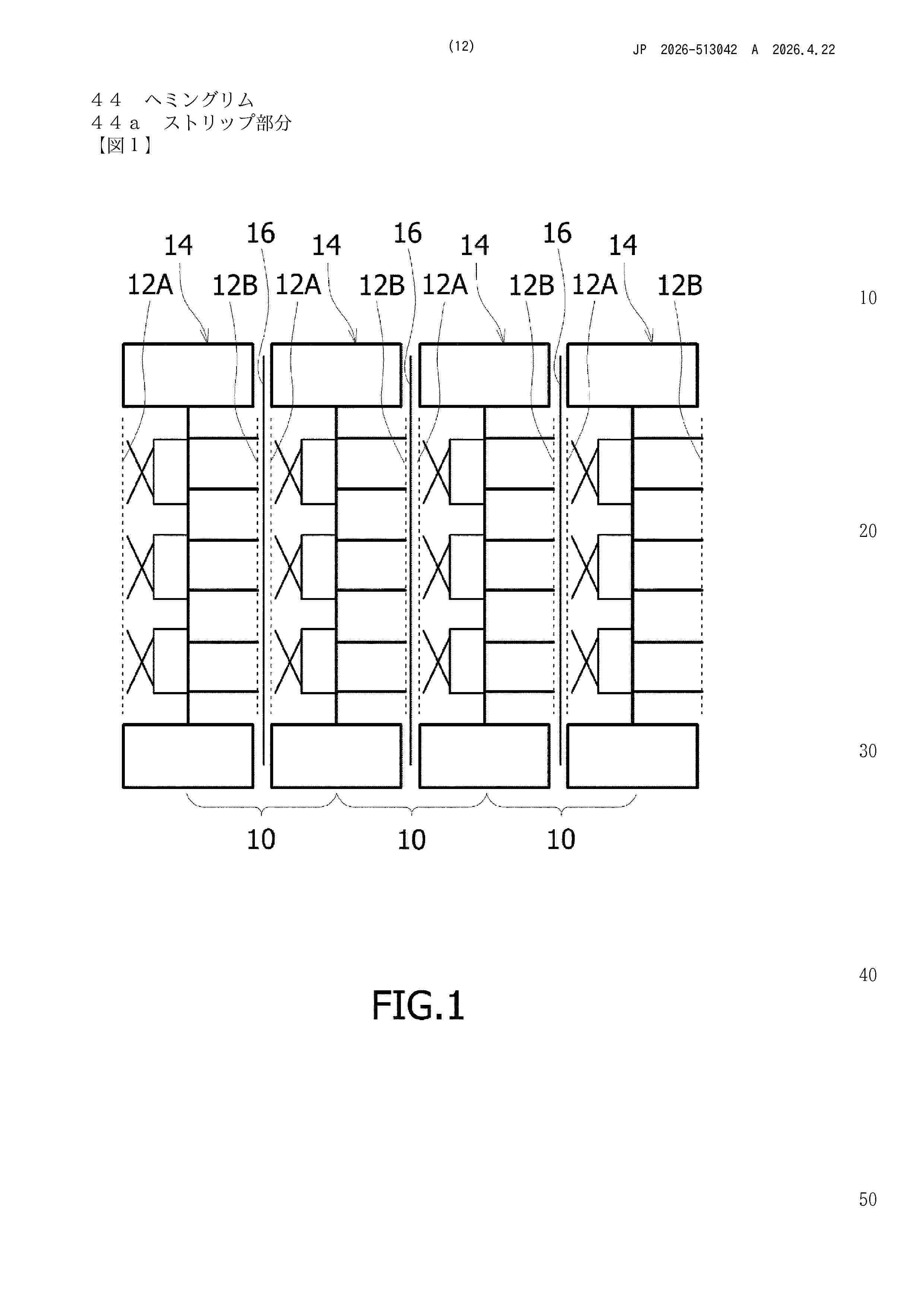
0001 The present invention relates to an electrochemical electrode structure comprising a current collector and at least one electrode element, wherein the at least one electrode element is a two-dimensionally extended electrically conductive element having an open structure. In this electrochemical electrode structure, the at least one electrode element has at least one edge with a hemming rim at which a strip portion of the electrode is hemming bent away. Moreover, the invention relates to an electrochemical cell comprising a first electrode, a second electrode and a separator, with either the first electrode or the second electrode or both electrodes being such an electrochemical electrode structure as well as to a method of retrofitting a finite-gap electrochemical cell into a zero-gap type electrochemical cell using such electrochemical electrode structure.
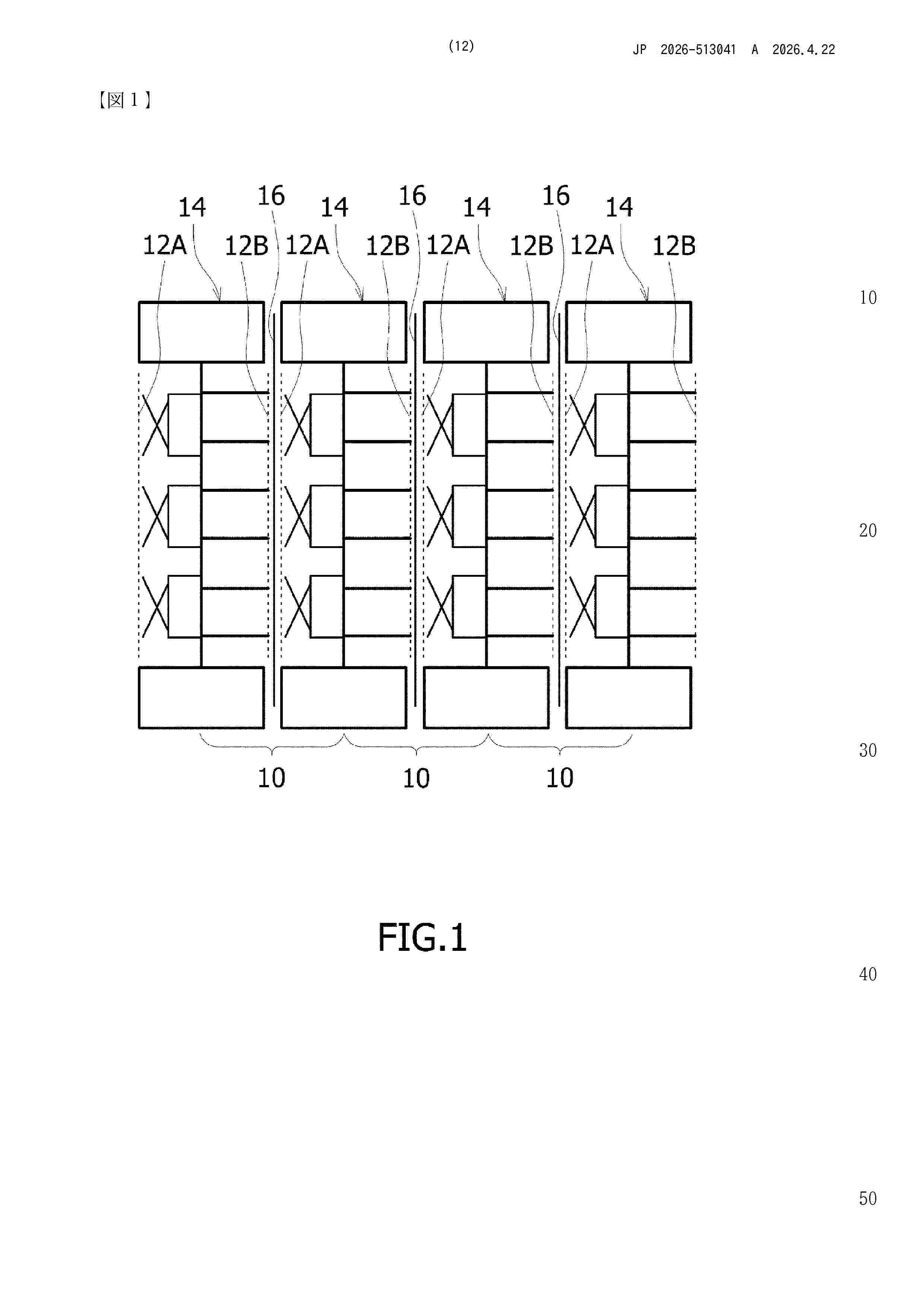
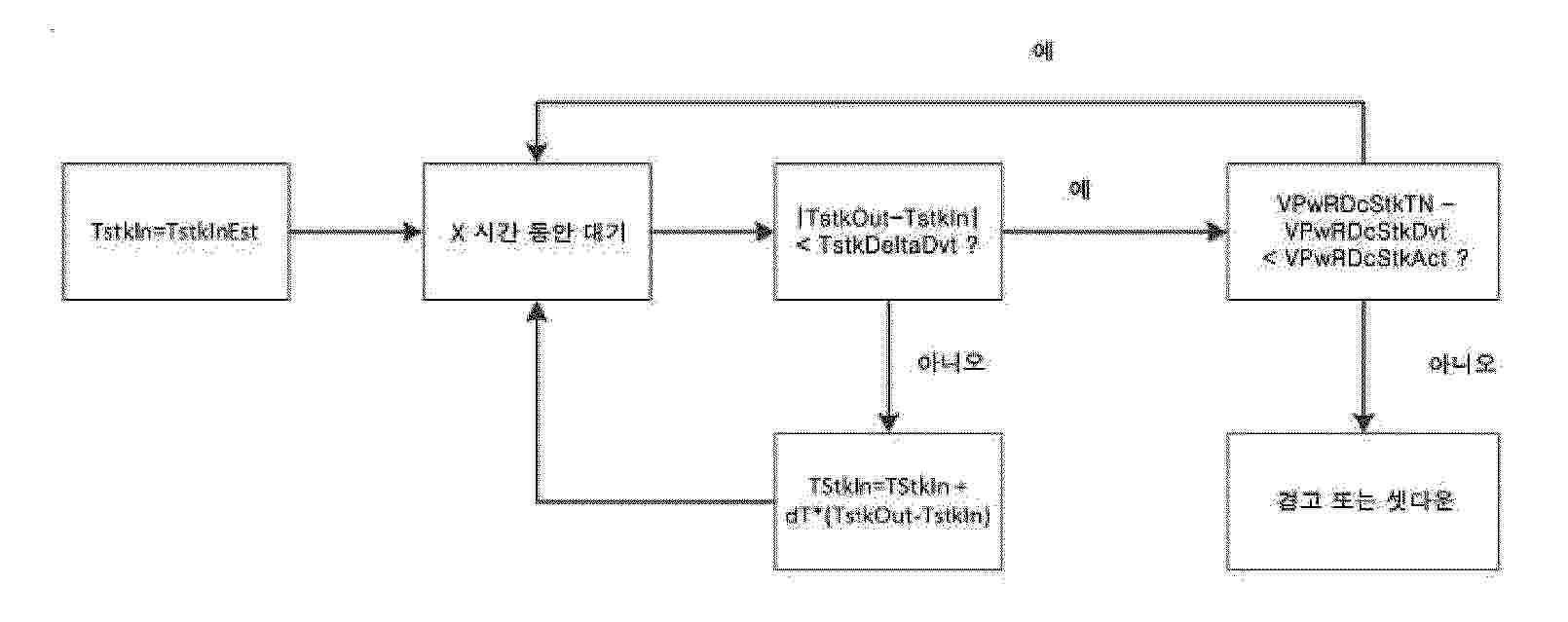
Resumen de: WO2024256820A1
The present invention provides a method of controlling an electrolyser cell stack within a system having a fluid temperature control system, a current control system, a voltage monitoring system, monitoring/control systems for the temperatures of the fluid inlet and outlet, by controlling the current to a fixed value, calculating a temperature delta between the fluid inlet and outlet, and adjusting the fluid input temperature if the delta is greater than a threshold value. The present invention also provides a method of determining a stack operating condition is the temperature delta as measured above is lower than a threshold value. The present invention also provides a control device and computer program capable of executing the method as outlined above.
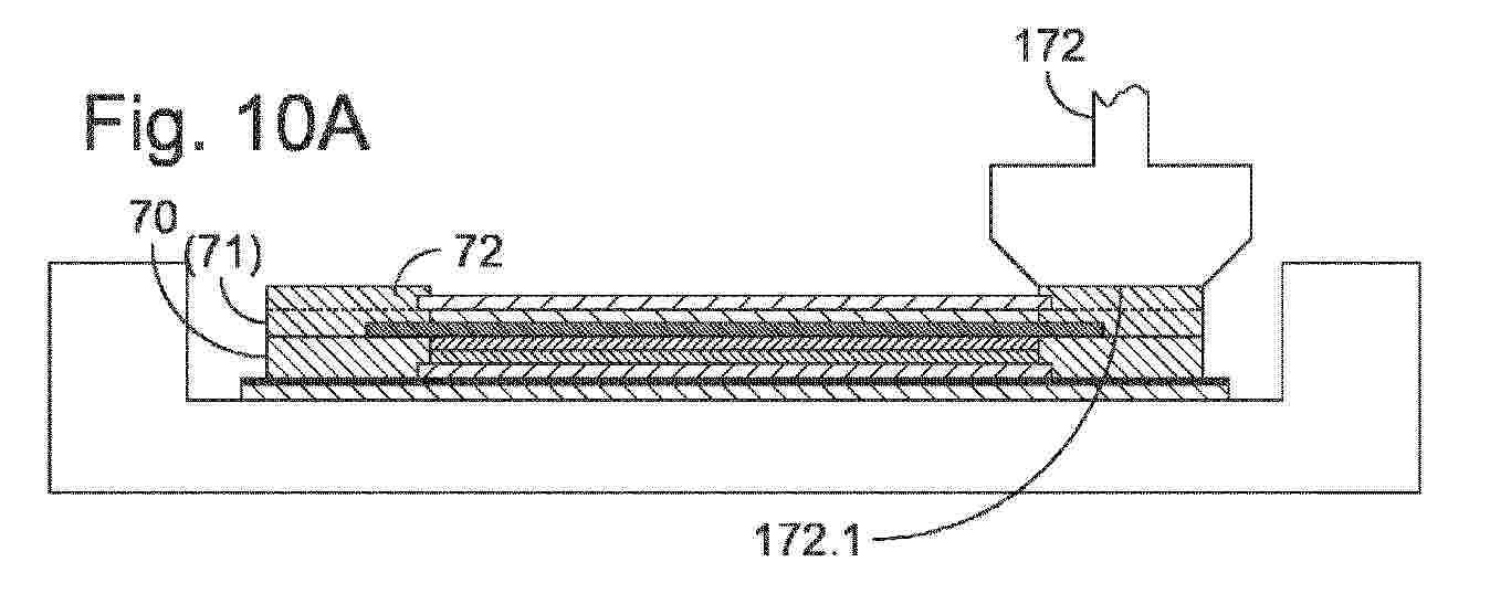
Resumen de: WO2024256503A1
The invention relates to a method for manufacturing an assembly for an electrochemical cell, wherein the assembly comprises at least the following structural components: a first plate (10; 10') for supplying and/or discharging fluid, a proton exchange membrane (42), a first electrode (31) arranged between the first plate and the proton exchange membrane, and a first gas diffusion layer (21) arranged between the first plate and the first electrode, and wherein the method comprises the steps of A) providing a base comprising only a portion of the structural components, in particular the first plate and/or the first gas diffusion layer; and B) assembling the assembly, wherein the assembling involves adding the remaining structural components; or the steps of a) providing a base that is different from the structural components; and b) assembling the assembly, wherein the assembling involves adding the structural components; wherein a casing is formed by applying one or more layers of moulding material (70-72) to the provided base, a strength of this moulding material increases after said application, and at least one layer of the moulding material forming the casing or at least a circumferential section of the casing is applied before step B) or b). The invention also relates to an electrochemical cell, in particular a fuel cell or electrolysis cell, a cell stack with cells of this type, as well as a method and a system for manufacturing assemblies for cells or cell stacks of thi
Resumen de: WO2024257054A1
The invention relates to an ion-conducting membrane (10) for an electrochemical device, said membrane comprising a layer of a material comprising: - 5% to 30% by weight of a polymer binder and - 70% to 95% by weight of a powdered ceramic, the powdered ceramic comprising ceramic doped with yttrium oxide and/or ceramic doped with cerium oxide. The invention can be used to produce a non-porous membrane for low-temperature electrolysis (0°C to 150°C).
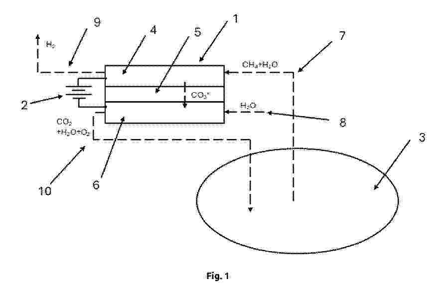
Resumen de: EP4729472A1
The invention relates to a method of converting methane from a natural gas field with simultaneous production of hydrogen and recovery of carbon dioxide. The method includes the steps of a steam reforming reaction of desulfurized methane in a co-electrolyzer (1), resulting in carbon monoxide and hydrogen; a water gas conversion reaction between carbon monoxide and water, resulting in carbon dioxide and additional hydrogen; a reaction between the carbon dioxide formed in step b) and water, resulting in an additional hydrogen molecule and a carbonate anion; a molten carbonate electrolysis reaction in which the carbonate anion CO32- is decomposed, producing oxygen, electrons and carbon dioxide, which is returned to the storage. In addition, the invention relates to the use of this method to store surplus energy from renewable energy sources.
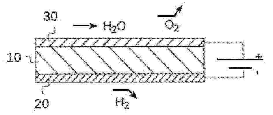
Resumen de: EP4729657A1
0001 A method is described for generating hydrogen by means of a PEM cell and water electrolysis, wherein leads of a photovoltaic solar panel, through which the panel supplies an electrical voltage and current towards its outside, are electrically connected by electrical conductors to electrical supply terminals of a PEM electrolytic cell which is external to the panel and designed to operate directly with the electrical voltage and current as generated at the leads.
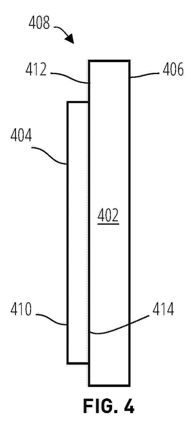
Resumen de: EP4729655A1
A layered bipolar plate (208) is provided that includes a steel layer (402) and a titanium layer (404). The steel layer (402), which is configured to be exposed to water and H2, is in contact to the titanium layer (404), which is configured to be exposed to water and 02. The titanium layer has an area that is smaller than the steel layer.
Nº publicación: EP4729660A2 22/04/2026
Solicitante:
SERVICES PETROLIERS SCHLUMBERGER [FR]
SCHLUMBERGER TECHNOLOGY BV [NL]
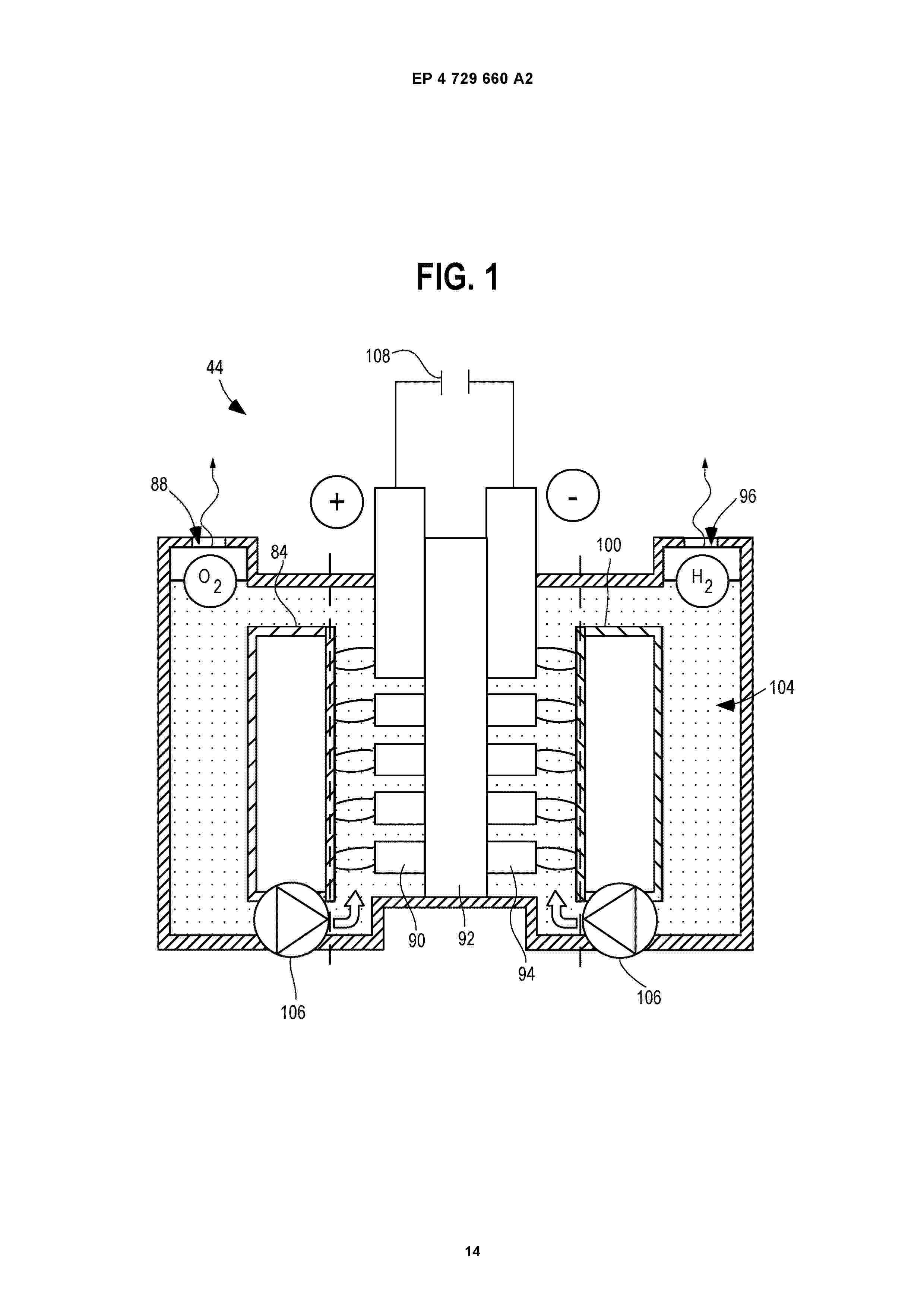
Resumen de: EP4729660A2
Provided herein are alkaline electrolyzer systems comprising one or more components that improve the performance, efficiency, and/or longevity of the system. For example, the alkaline electrolyzer system may comprise one or more of (1) a filtration component comprising one or more filtration media, (2) an ion exchange component comprising at least one ion exchange resin, (3) a corrosion inhibition component configured to introduce at least one corrosion inhibitor into the electrolyte solution, and (4) a chelating agent component configured to introduce at least one chelating agent into the electrolyte solution.
 BOPI
BOPI
 Sede Electrónica