Si deseas distinguir tus productos, servicios o ambos de los de otra empresa, es posible que necesites una marca o nombre comercial. Descubre qué son, en qué consiste su procedimiento de registro y qué implica.

Información sobre los plazos de presentación de solicitudes de transformación de marcas de la Unión Europea en marca nacional española. Más información


Si tienes un nuevo dispositivo, producto o procedimiento que resuelva un problema técnico o tenga una ventaja práctica, existen distintas formas de protegerlo en España y en otros países. Descubre cómo hacerlo.

¿Tu innovación reside en la estética, la ornamentación o la apariencia de tu producto? Protégela mediante un diseño industrial. Descubre qué derechos confiere el registro y cómo realizar la tramitación.

Las indicaciones geográficas protegen el nombre de un producto originario de una zona geográfica, a la cual le debe una determinada calidad, reputación u otra característica. Descubre qué son, en qué consiste su procedimiento de registro y qué beneficios conceden.

Las patentes publicadas en todo el mundo son una valiosa fuente de información científica, técnica y comercial.

Si eres emprendedor/a o una empresa y quieres potenciar y mejorar la rentabilidad de tu negocio protegiendo de forma adecuada los activos intangibles de tu organización, en este espacio encontrarás lo necesario.


 1176
resultados
1176
resultados
 Última actualización
19/07/2026 [06:59:00]
Última actualización
19/07/2026 [06:59:00]


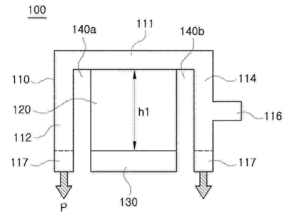
Resumen de: WO2025135743A1
The present invention provides a water electrolysis stack assembly and a hot box apparatus. In an embodiment, provided is a water electrolysis stack assembly including: a case including an upper surface part, a side surface part, and a gas outflow pipe formed in the side surface part; and a stack accommodated in an inner space of the case, wherein a surface pressure is applied to the stack by the upper surface part of the case.

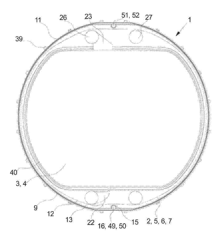
Resumen de: WO2025132935A1
Disclosed is an electrolysis cell stack (10) comprising a plurality of support structures (2) each including an inner aperture (3). The electrolysis cell stack (10) further comprises a plurality of cathodes (17), a plurality of anodes (18), a plurality of bipolar plates (4), a plurality of gas impermeable membranes (19), and pressing means 5 (20) arranged for pressing neighbouring support structures (2) of the plurality of support structures (2) against each other. Further, the electrolysis cell stack (10) comprises a liquid conduit (13) arranged between neighbouring support structures (2) of the plurality of support structures (2), wherein the liquid conduit (13) is arranged outside an outer periphery (40) of the inner aperture (3), deionized water (41) arranged 10 in the liquid conduit (13), and conductivity monitoring means (42) arranged for monitoring a conductivity of the deionized water (41). 0111 A method for detecting a leak in an electrolysis cell stack (10) and use of an electrolysis cell stack (10) is also disclosed.
Resumen de: WO2025135742A1
A control method of a high-temperature water electrolysis system, according to a first embodiment of the present invention, comprises the steps of: determining an operating temperature of a solid oxide water electrolysis stack in a high-temperature water electrolysis system including the solid oxide water electrolysis stack; selecting an operation mode of the solid oxide water electrolysis stack by comparing the operating temperature with a supply temperature of gas supplied to the solid oxide water electrolysis stack; determining a target voltage applied to the solid oxide water electrolysis stack according to the operation mode of the solid oxide water electrolysis stack; and applying the target voltage applied to the solid oxide water electrolysis stack in a step-up manner according to the operation mode of the solid oxide water electrolysis stack.
Resumen de: WO2025135512A1
The present disclosure relates to: a catalyst for an oxygen evolution reaction of a water electrolysis cell; a method for manufacturing same; and a membrane-electrode assembly for a water electrolysis cell, and a water electrolysis cell, comprising same. More specifically, by manufacturing a catalyst for oxygen evolution reaction of a water electrolysis cell, having a structure in which active particles fill pores between nanoparticles of a carrier assembly manufactured in various forms or penetrate into the carrier assembly while being supported by the carrier assembly, performance is improved while reducing the amount of noble metal used. The active particles have stronger bonds than a form in which active particles are simply supported, and thus the active particles and the carrier assembly can have improved durability.
Resumen de: WO2025132918A1
Disclosed is an electrolysis cell element (1) comprising, a support structure (2) comprising an inner aperture (3), and a bipolar plate (4) being suspended in the inner aperture (3). The support structure (2) comprises a structure core (5) and a coating (6), wherein the coating (6) includes a thermoplastic material at least partly enclosing the structure core (5) and wherein the bipolar plate (4) is suspended in the inner aperture (3) by means of the coating (6). An electrolysis cell stack (10) and use of an electrolysis cell stack (10) is also disclosed.
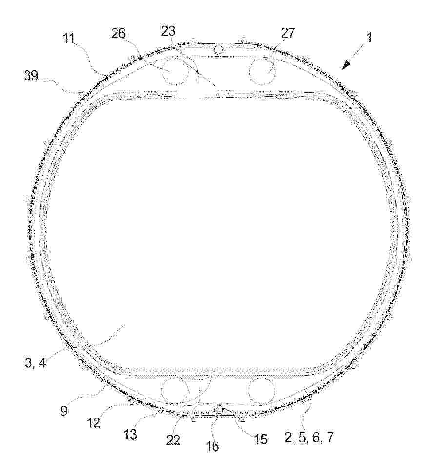
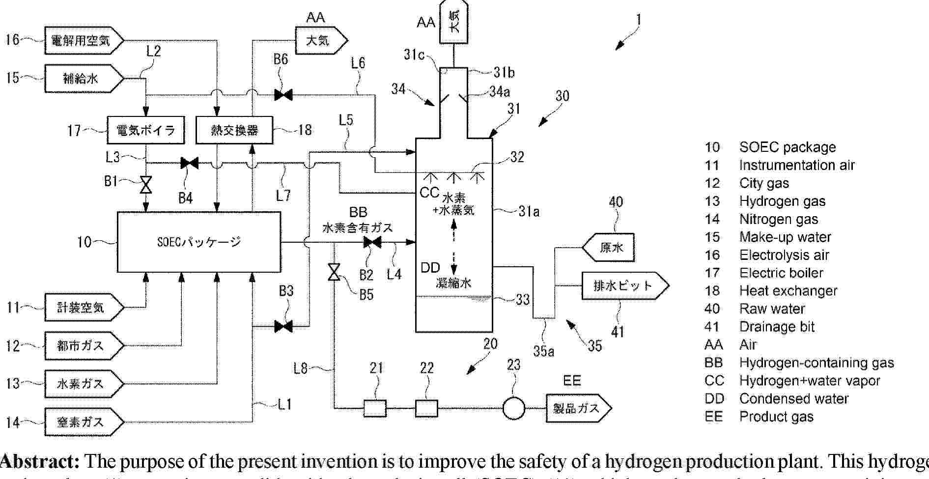
Resumen de: AU2024420375A1
The purpose of the present invention is to improve the safety of a hydrogen production plant. This hydrogen production plant (1) comprises: a solid oxide electrolysis cell (SOEC) (10) which produces a hydrogen-containing gas; and a discharge stack (30) into which the hydrogen-containing gas produced by the SOEC (10) is introduced and which discharges the introduced hydrogen-containing gas to air. The discharge stack (30) has a spray unit (32) which supplies, to the hydrogen-containing gas introduced therein, cooling water for cooling the hydrogen-containing gas.
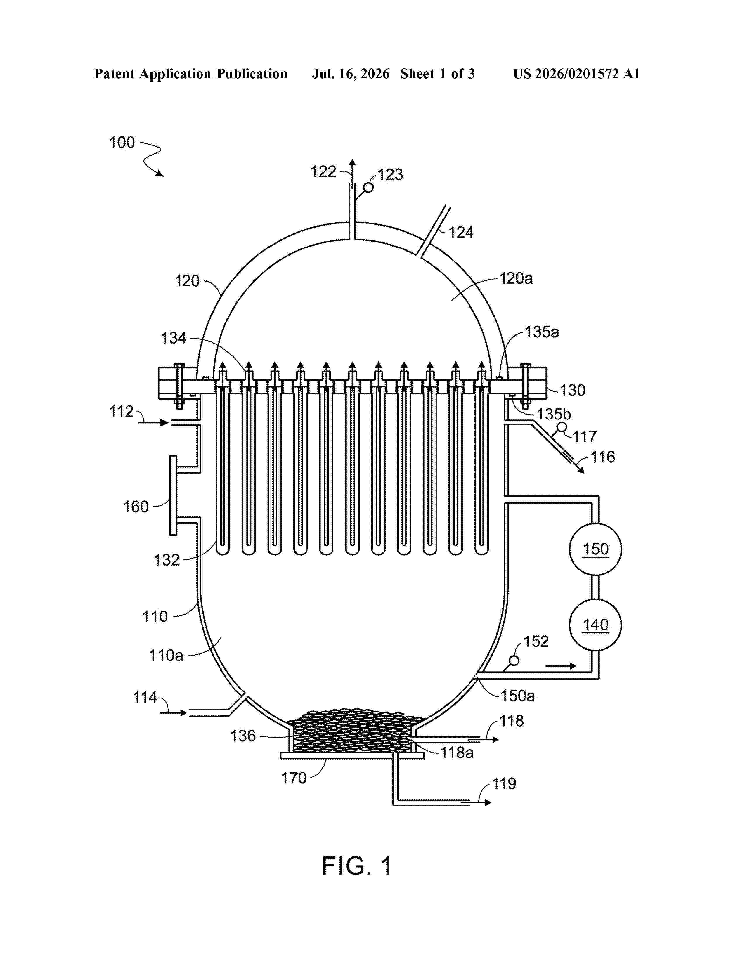
Resumen de: US20260201572A1
0000 A reactor is configured to electrochemically convert hydrogen sulfide to produce hydrogen. The reactor includes a first shell, a second shell, a hydrogen-permeable electrode, and a check valve. The first shell defines a first chamber. The first shell defines a first inlet for water, a second inlet for hydrogen sulfide, and a first outlet for hydrogen sulfide. The second shell defines a second chamber isolated from the first chamber. The second chamber stores hydrogen molecules. The hydrogen-permeable electrode is at least partially disposed within the first chamber. The hydrogen-permeable electrode is permeable to hydrogen atoms originating from the hydrogen sulfide. The check valve allows flow of hydrogen molecules, formed from the hydrogen atoms that have permeated into the hydrogen-permeable electrode, into the second chamber while preventing flow of hydrogen molecules back out from the second chamber through the check valve.
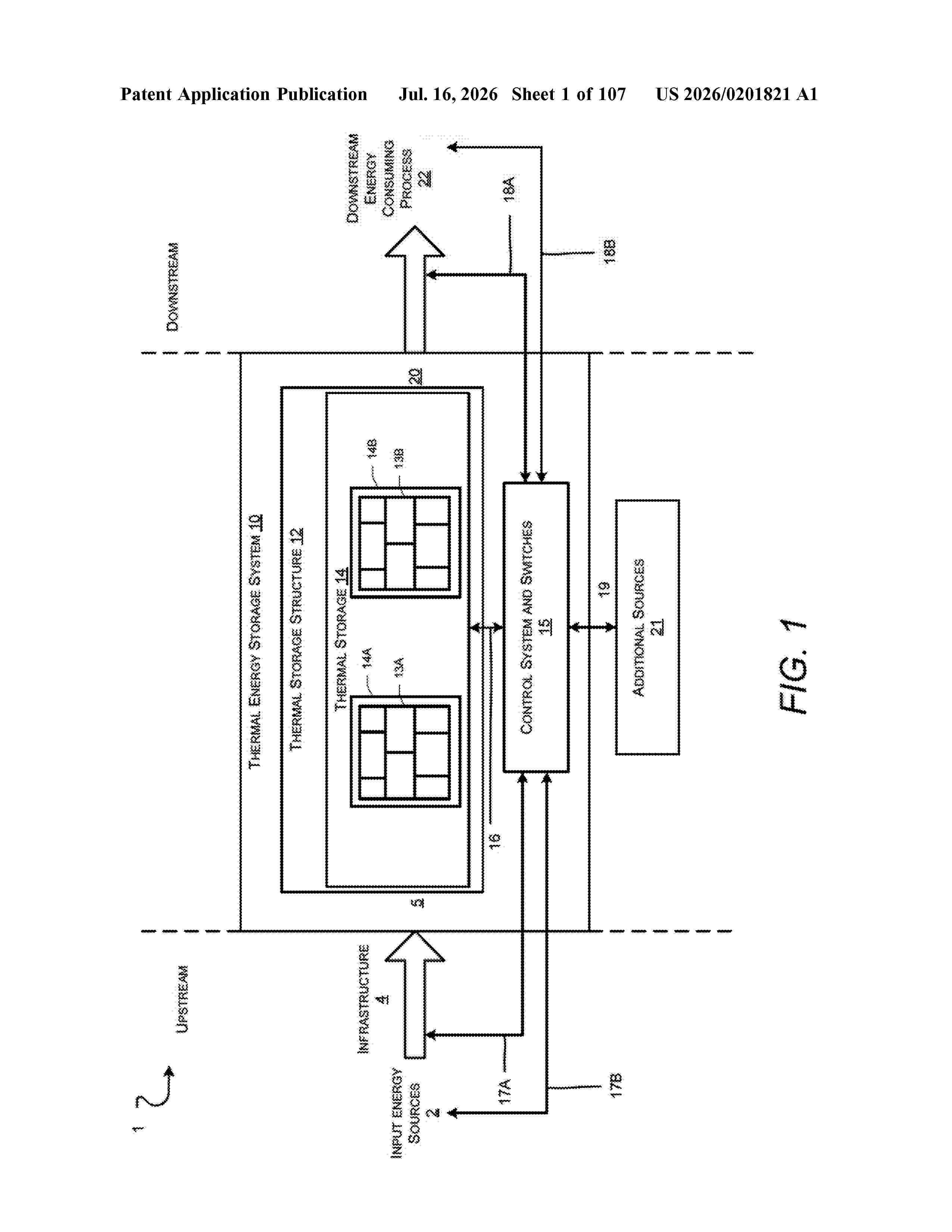
Resumen de: US20260201821A1
A thermal energy storage system with fluid flow insulation, the system including heated thermal storage blocks positioned within a housing, and a method for operating the thermal energy storage system, including providing a flow of fluid into the housing, the fluid convectively extracting heat from a top region, a side region and a bottom region of the thermal energy storage system, to generate heated fluid that insulates the thermal storage blocks from the housing and a foundation of the thermal energy storage system.
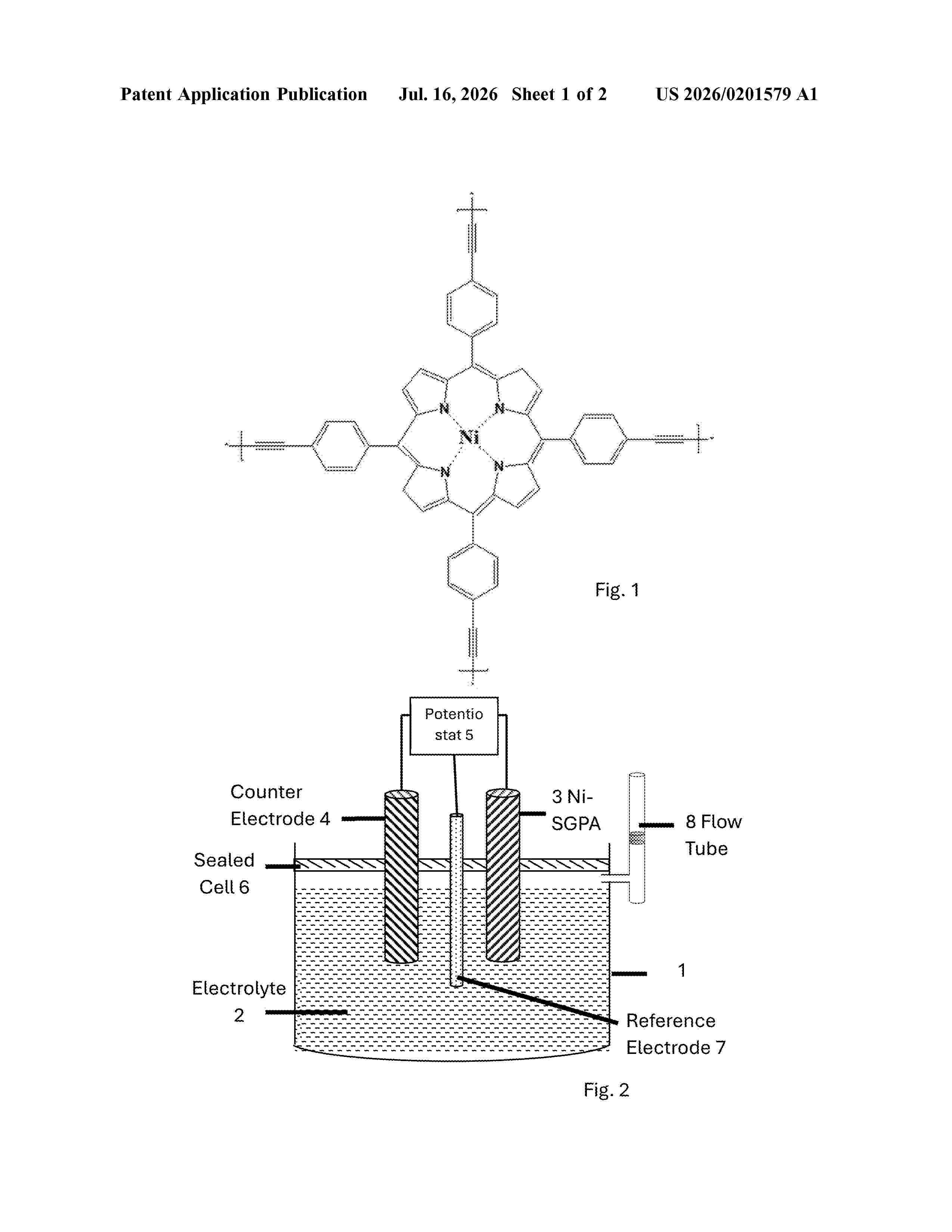
Resumen de: US20260201579A1
A hydrogen-producing cell includes a first and second electrode. The first electrode includes a cathode that includes a nickel single-atom graphdiyne porphyrin analogue (Ni-SGPA) catalyst material deposited on a substrate and the second electrode that includes an anode and a reference electrode. The electrolyte includes H2SO4. The cell also includes an electric power supply for applying a pulsed voltage between the foil and a reference electrode and counter electrode. Another hydrogen-producing cell includes a first and second electrode. The first electrode includes a cathode that includes a nickel single-atom graphdiyne porphyrin analogue (Ni-SGPA) catalyst material deposited on a substrate and the second electrode includes an anode and a reference electrode. The electrolyte includes KOH. The cell also includes an electric power supply for applying a pulsed voltage between the foil and a reference electrode and counter electrode.
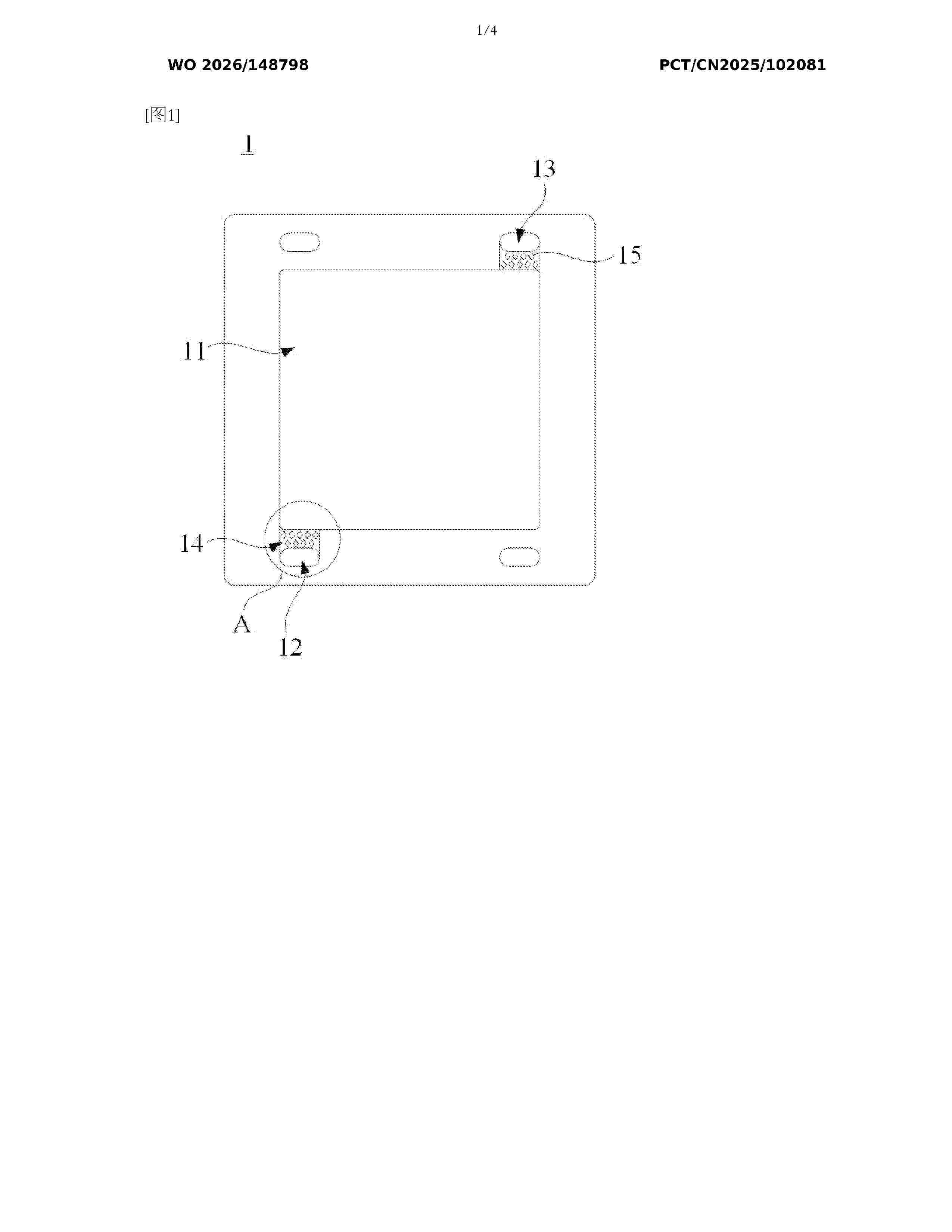
Resumen de: WO2026148798A1
The present application provides an electrode frame, a flow field plate assembly, and an electrolytic cell. The electrode frame is applied to the flow field plate assembly, and is provided with an accommodating cavity, a water inlet, a water outlet, and a first flow distribution channel, the accommodating cavity is configured to accommodate a plate mesh, and the water inlet is in communication with the accommodating cavity by means of the first flow distribution channel. The electrode frame further comprises flow distribution rows, each flow distribution row comprises at least two flow distribution members spaced apart, and the first flow distribution channel is internally provided with at least two flow distribution rows.
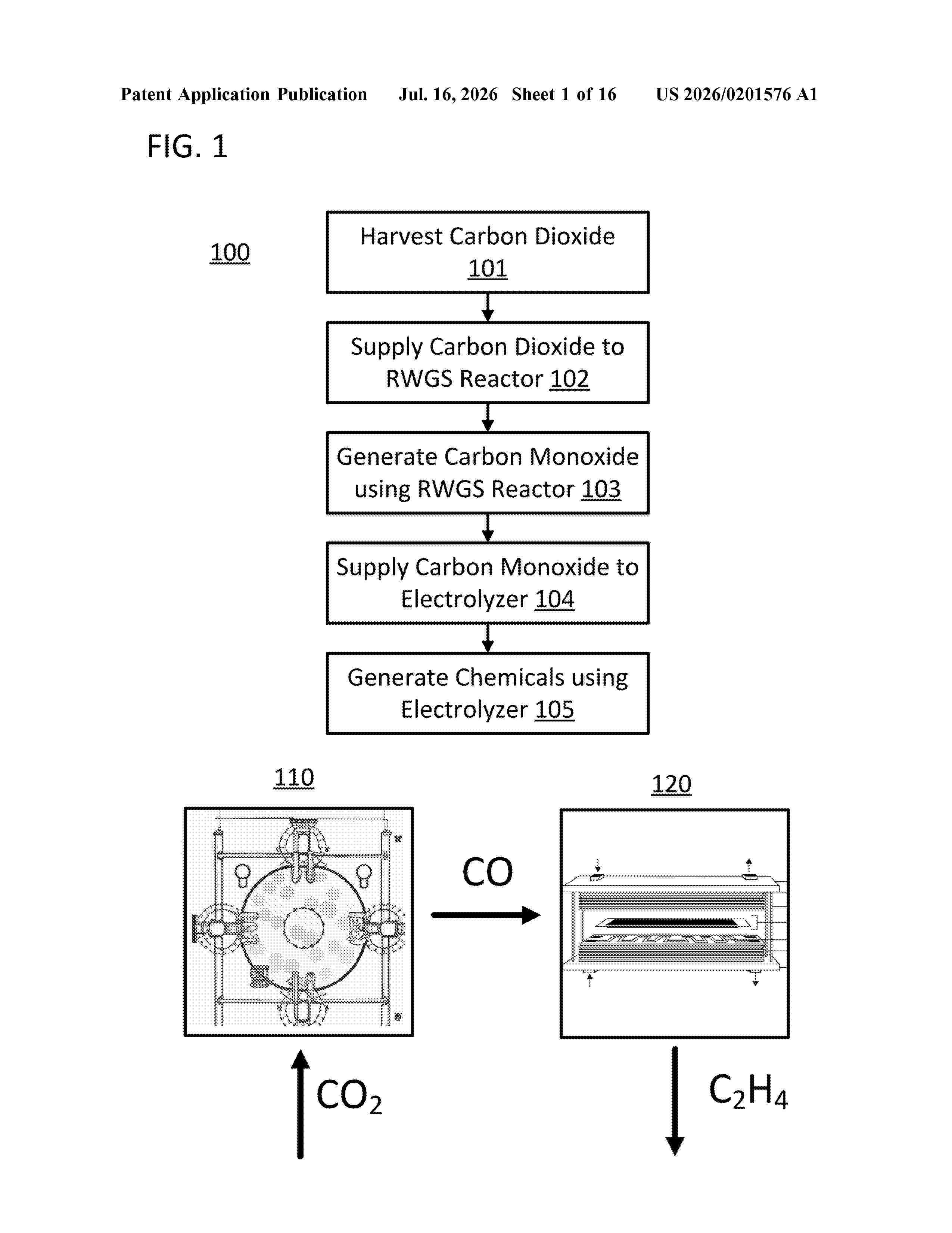
Resumen de: US20260201576A1
Methods and systems related to valorizing carbon dioxide are disclosed. A disclosed system includes a reverse water gas shift (RWGS) reactor, a carbon dioxide source connection fluidly connecting a carbon dioxide source to the RWGS reactor, an electrolyzer having an anode area and a cathode area, and a carbon monoxide source connection fluidly connecting the RWGS reactor to the cathode area. The RWGS reactor is configured to generate, using a volume of carbon dioxide from the carbon dioxide source connection, a volume of carbon monoxide in an RWGS reaction. The electrolyzer is configured to generate, using the electrolyzer and a reduction of the volume of carbon monoxide from the carbon monoxide source connection and an oxidation of an oxidation substrate, a volume of generated chemicals including hydrocarbons, organic acids, alcohol, olefins, or N-rich organic compounds.
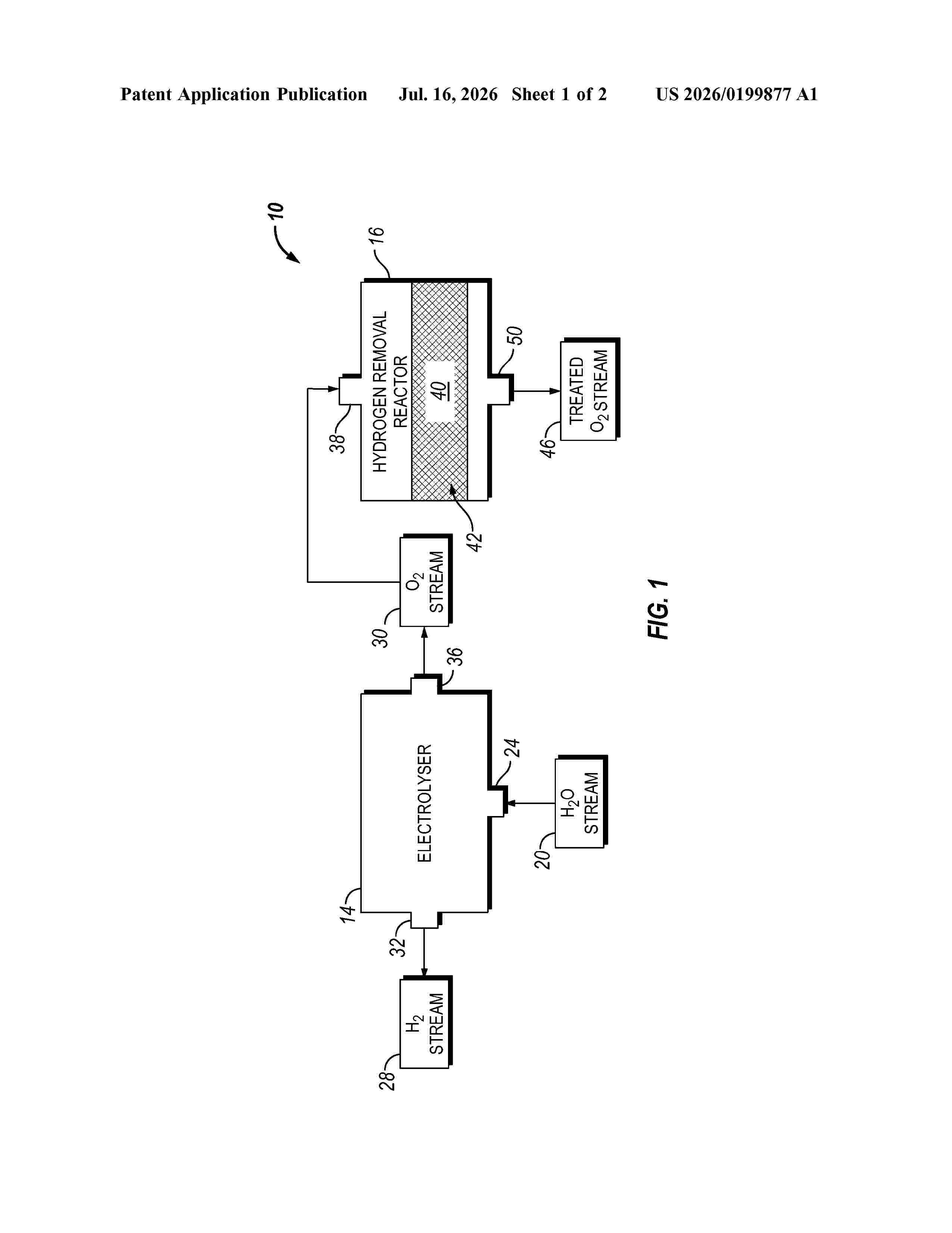
Resumen de: US20260199877A1
0000 A process for removing hydrogen from an oxygen gas stream includes electrolysing water in an electrolyser to generate a hydrogen-rich stream and an oxygen-rich stream. The oxygen-rich stream includes hydrogen. The process also includes feeding the oxygen-rich stream to a reactor having a gold-containing catalyst and contacting, in the reactor, the oxygen-rich stream with the gold-containing catalyst. The gold-containing catalyst includes gold and a second metal on an oxidic support and an oxygen partial pressure of the oxygen-rich stream in the reactor is greater than 1 bar.
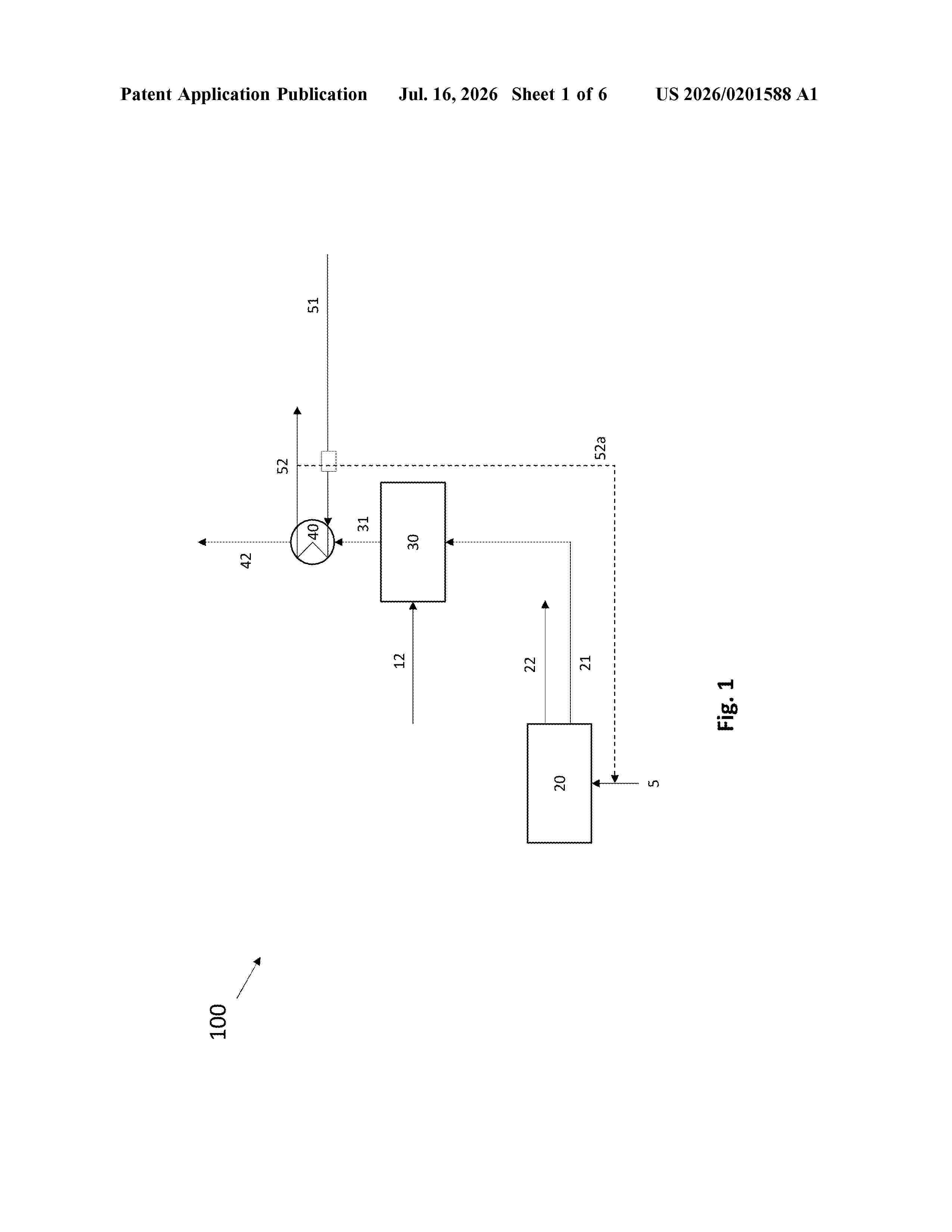
Resumen de: US20260201588A1
0000 A chemical plant in which an electrolysis section is arranged to receive at least a portion of a first steam feed and electrolyze it to provide a hydrogen stream and an oxygen-enriched stream. A first heat exchanger is arranged to receive at least a portion of the oxygen-enriched stream and a combustion air stream to transfer heat from the oxygen-enriched stream to the combustion air stream. The heated combustion air stream and at least a portion of an off-gas stream are arranged to be combusted in at least one burner to provide a combusted gas stream. The first heat exchanger is arranged to receive at least a portion of the combusted gas stream and said water stream. The first heat exchanger is arranged to transfer heat from the at least a portion of the combusted gas stream to the water stream to provide a cooled combusted gas stream and a steam stream.
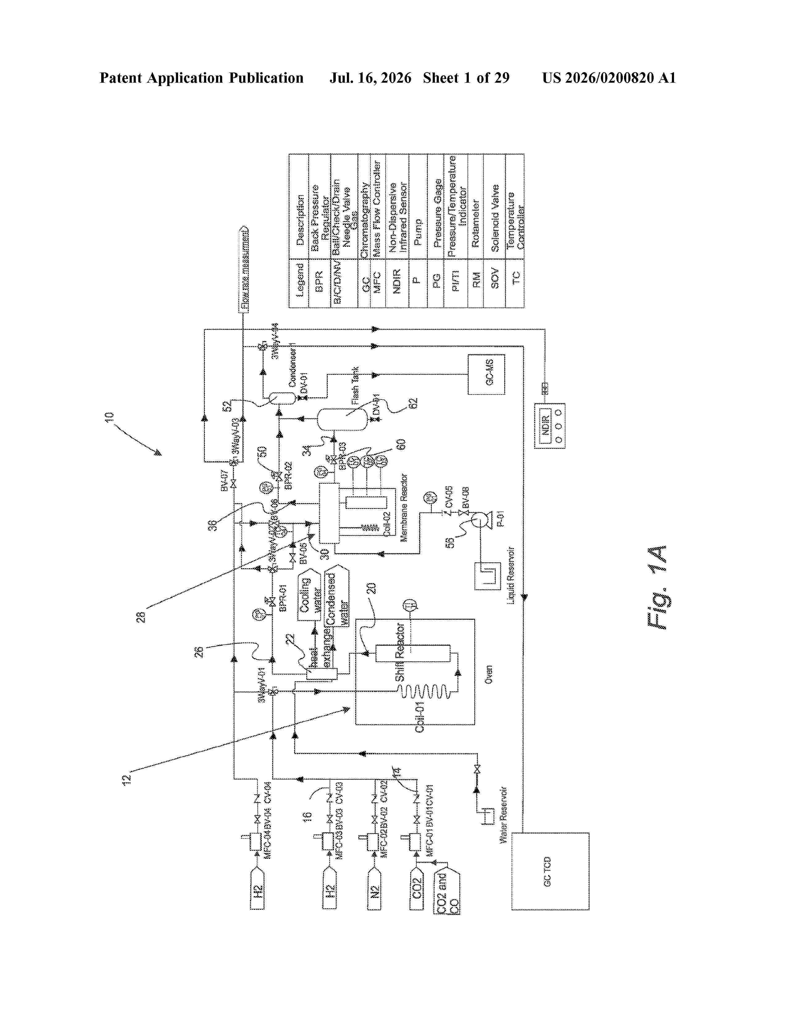
Resumen de: US20260200820A1
0000 A system for converting CO<2 >to methanol includes a reverse water gas shift (“RWGS”) reactor configured to receive a first CO<2 >stream and a hydrogen gas stream under a sufficient temperature and a sufficient pressure for an RWGS reaction to proceed. The RWGS reactor outputs an exit stream that includes CO. The system also includes a heat exchanger/condenser in fluid communication with the RWGS reactor configured to remove water from products of the RWGS reaction to form a dried exit stream that includes CO; and a membrane contactor reactor configured to receive a combination of hydrogen, CO<2>, and the dried exit stream. The membrane contactor reactor also configured to output a first output stream including methanol dissolved in a sweep liquid and a second output stream including gaseous H<2>, gaseous CO, gaseous CO<2>, and gaseous methanol.
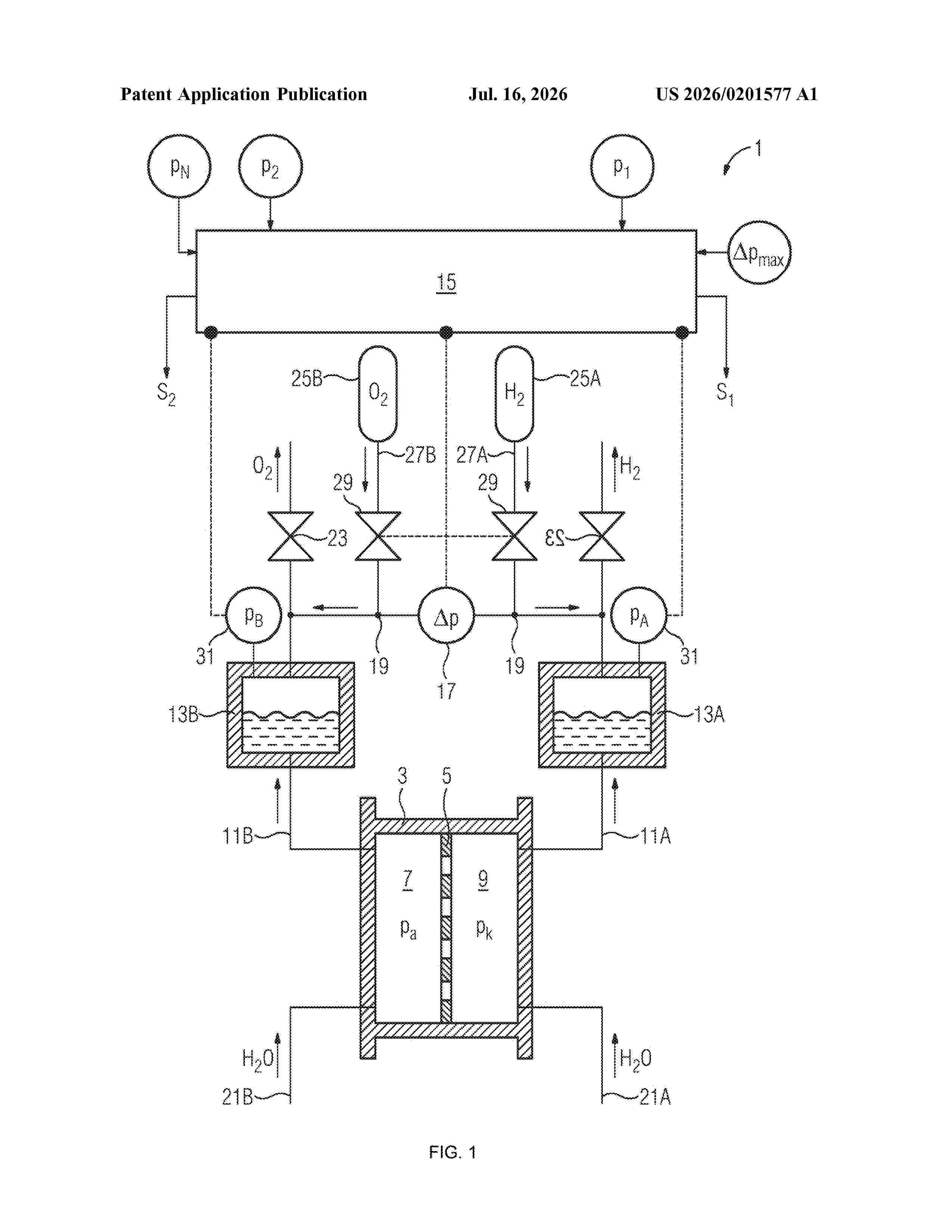
Resumen de: US20260201577A1
0000 The invention pertains to an electrolysis system with a high-pressure electrolyzer for producing hydrogen (H2) and oxygen (O2) at a nominal pressure (PN). The system includes multiple electrolysis cells, each with two half-cells separated by an ion-permeable membrane, forming an anode chamber and a cathode chamber. An oxygen product line connects to the anode chamber, while a hydrogen product line connects to the cathode chamber. The hydrogen and oxygen product lines lead to respective gas separators. The system features compressed gas accumulators for hydrogen and oxygen, enabling pressurized gas to be supplied to the electrolyzer on both sides, with adjustable primary pressures. The invention also includes a method for operating the system, where the electrolyzer is precharged with pressurized gas, and differential pressures are regulated to ensure efficient operation. This system supports both proton-exchange membrane (PEM) and alkaline electrolysis for high-pressure hydrogen and oxygen production.
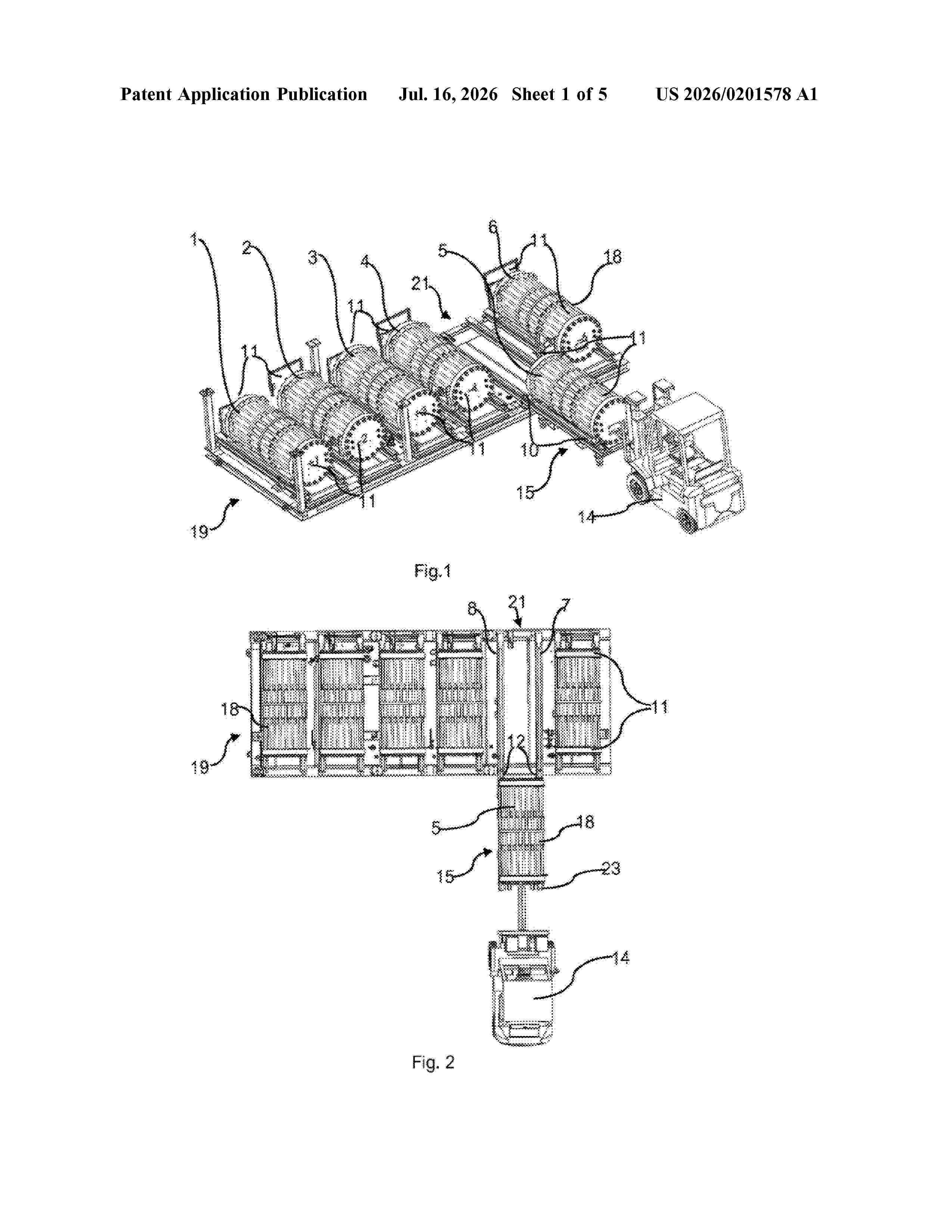
Resumen de: US20260201578A1
0000 Electrolyser stack and production unit are provided, in which the electrolyser stack include endplates and pull rods extending between the endplates. Feet are arranged at the endplates whereby each foot includes a downwardly directed support surface arranged to abut onto a production unit track or handling unit track whereby the production unit tracks are arranged to extend in parallel with the length axis of the electrolyser stack and whereby the electrolyser stack is movable along the production unit track by sliding the feet along upward facing horizontal slide tracks of the production unit track.
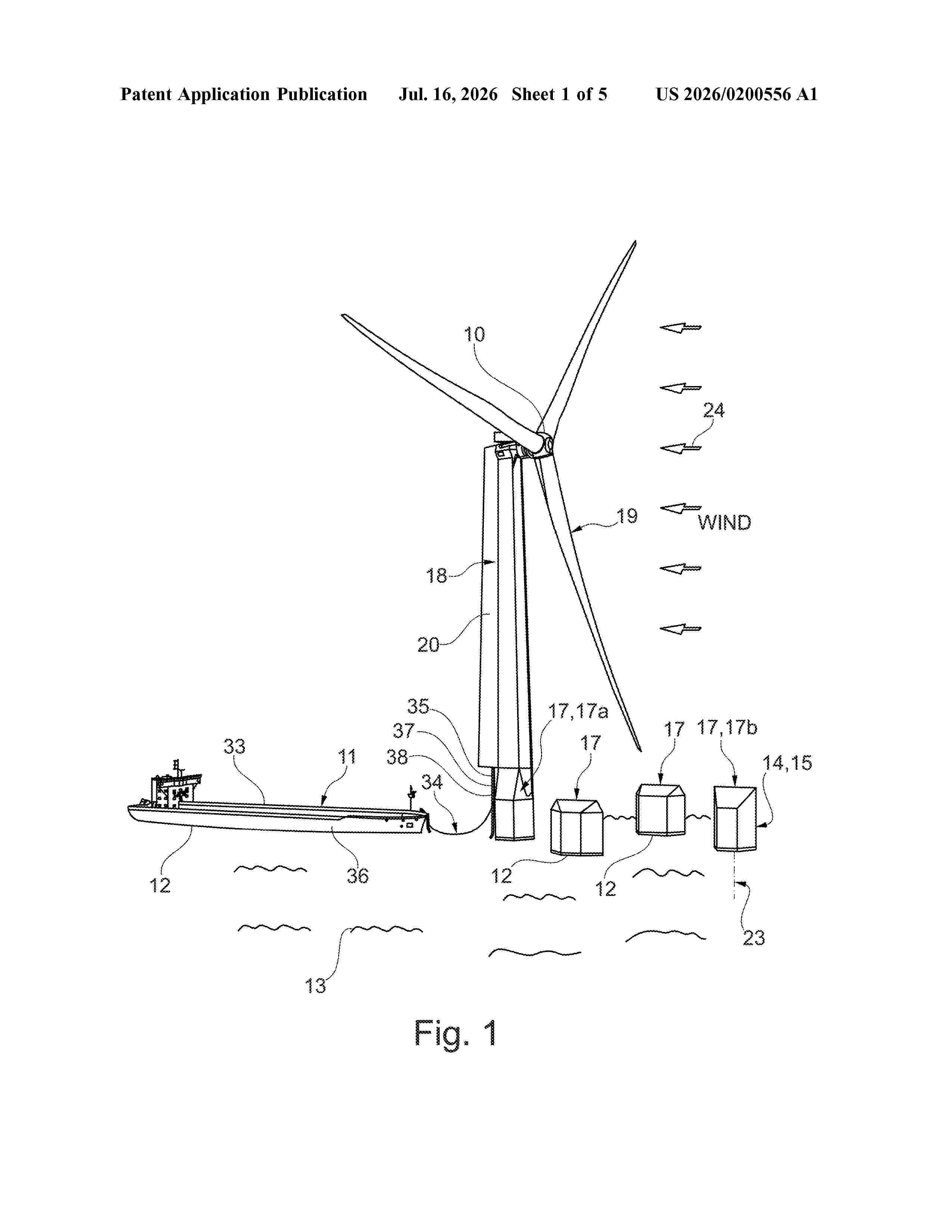
Resumen de: US20260200556A1
A method (100) for transporting hydrogen from a floating wind turbine (10) to a watercraft (11) is proposed in order to transport environmentally friendly energy generated by an offshore wind turbine from the offshore wind turbine to land in a simple and safe manner, wherein hydrogen is provided in a holding tank (31) of a floating wind turbine (10), wherein a watercraft (11) with a transportation tank (36) is positioned at the floating wind turbine (10), wherein the hydrogen is conveyed from the holding tank (31) to the transportation tank (36) by means of a line (35) configured to convey the hydrogen.
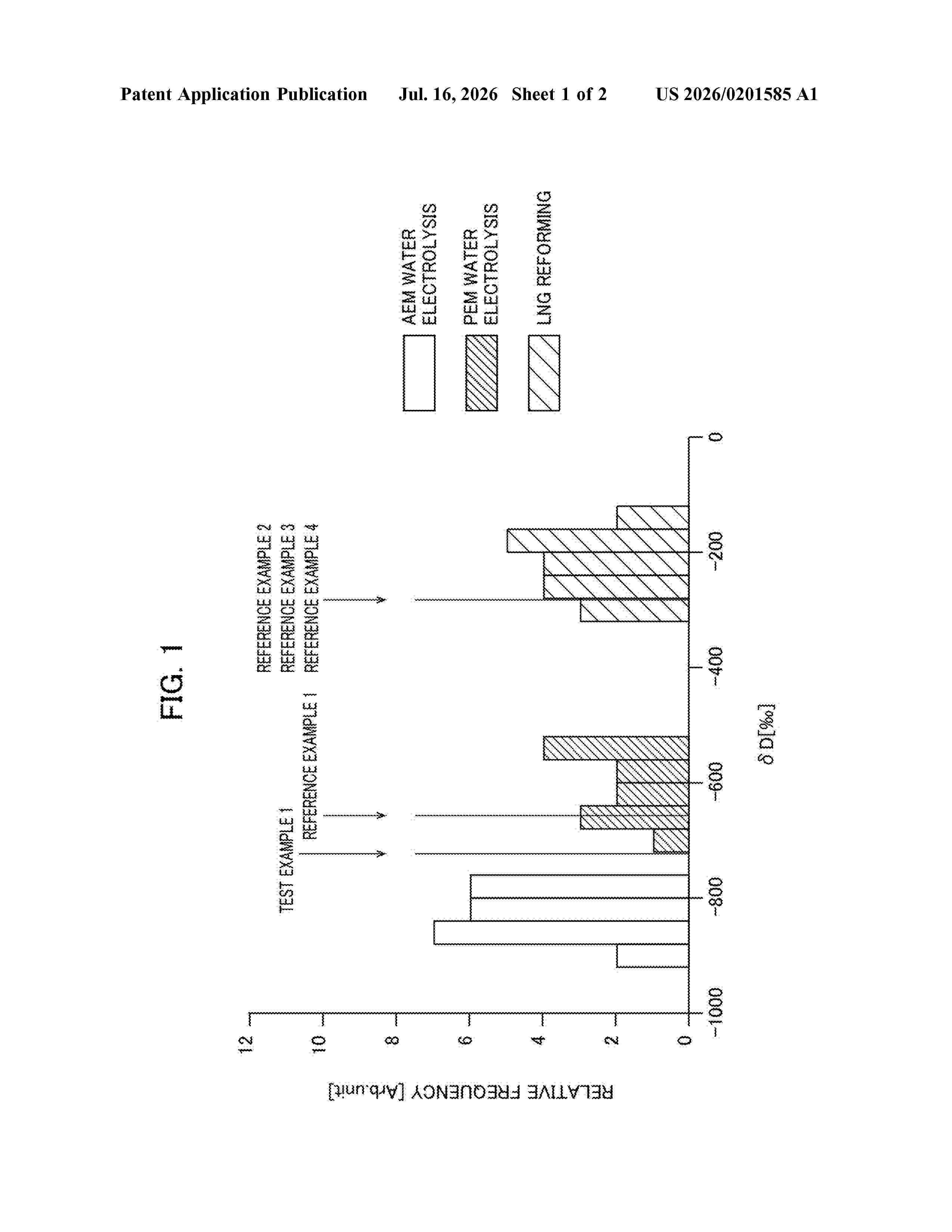
Resumen de: US20260201585A1
A manufacturing process determination method for a determination target molecule includes obtaining an isotope ratio δD of deuterium to protium contained in the determination target molecule; and determining that the determination target molecule is a molecule produced using a method including electrolyzing for generating hydrogen molecules by electrolysis of a liquid containing water when the isotope ratio δD is less than or equal to a predetermined threshold value.
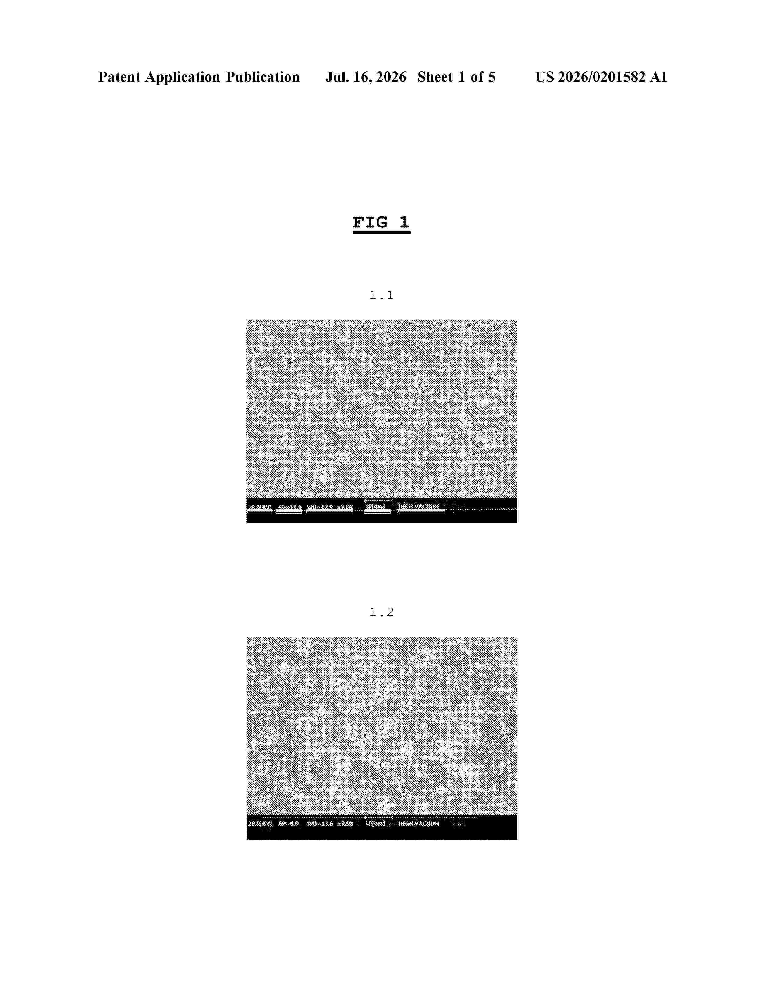
Resumen de: US20260201582A1
0000 A symmetrical separator membrane for electrolysis of alkaline water and with homogeneous distribution of the pores. The membranes are obtained by dissolving a thermoplastic polymer in a dispersion comprising inorganic filler and organic solvent, degassing the solution, creating a membrane by applying the solution to a permeable medium positioned at the centre, with a double side casting technique in a coagulation bath, washing the membrane with alcohol, and drying the membrane. 0000 The present invention relates to a symmetrical separator membrane for electrolysis of alkaline water and with homogeneous distribution of the pores.
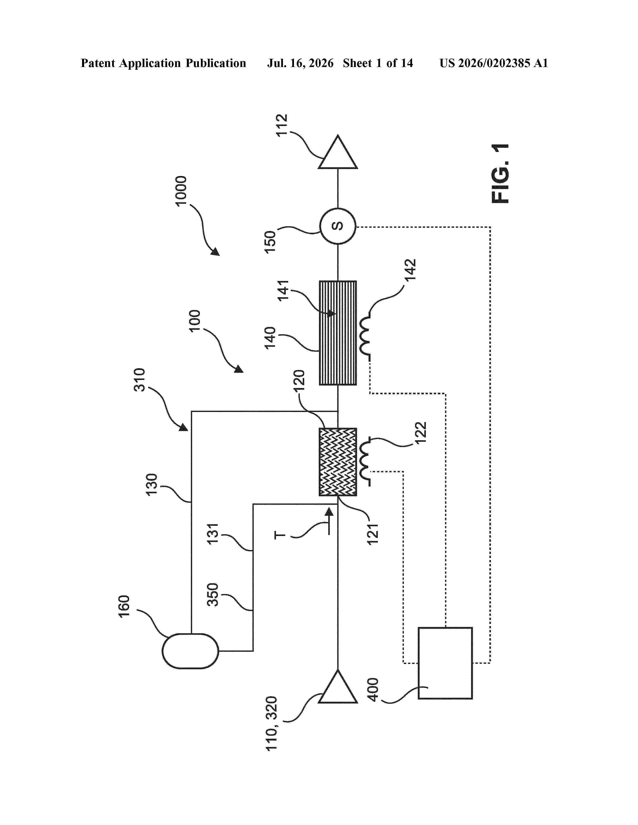
Resumen de: US20260202385A1
0000 The invention relates to a gas chromatographic system (1000) for detecting volatile organic compounds in an analyte (320) with a gas chromatograph (100) having an injector for injecting analyte (320), a pre-concentrator (120), a column (140) equipped with a stationary phase (141) and a gas detector (150) configured to detect the analyte (320) component eluted from the column (140). The invention suggests an aggregate (160) having an outlet coupled to the gas chromatograph (100) and being configured to receive and process a hydrogen containing medium (330) for generating hydrogen (310) and supplying the hydrogen (310) to the gas chromatograph (100). The invention further relates to such an aggregate (160) and to a method of operating such a chromatographic system.
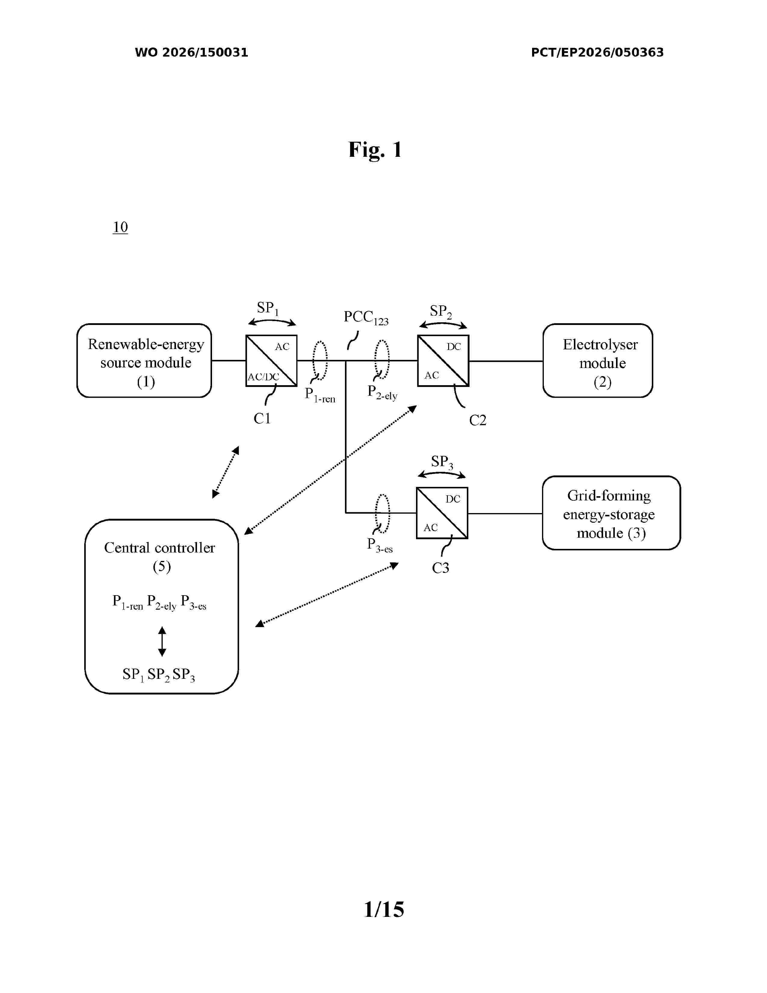
Resumen de: WO2026150031A1
The disclosure relates to efficient systems (10, 100) and methods for green-hydrogen production. A system (10) for off-grid green-hydrogen production is provided, the system (10) comprising: a renewable-energy source module (1) configured to provide power from one or more renewable-energy sources, an electrolyser module (2) configured to produce green hydrogen based on the power provided by the renewable-energy source module (1), a grid-forming energy-storage module (3) configured to provide grid-forming capabilities to the renewable-energy source module (1) and the electrolyser module (2), a plurality of power-converter modules (C1, C2, C3) configured to allow power flow between the renewable-energy source module (1), the electrolyser module (2), and the grid-forming energy-storage module (3), which are electrically connected to each other, and a central controller (5) configured to control the power flow by controlling the plurality of power-converter modules (C1, C2, C3).
Resumen de: AU2025211056A1
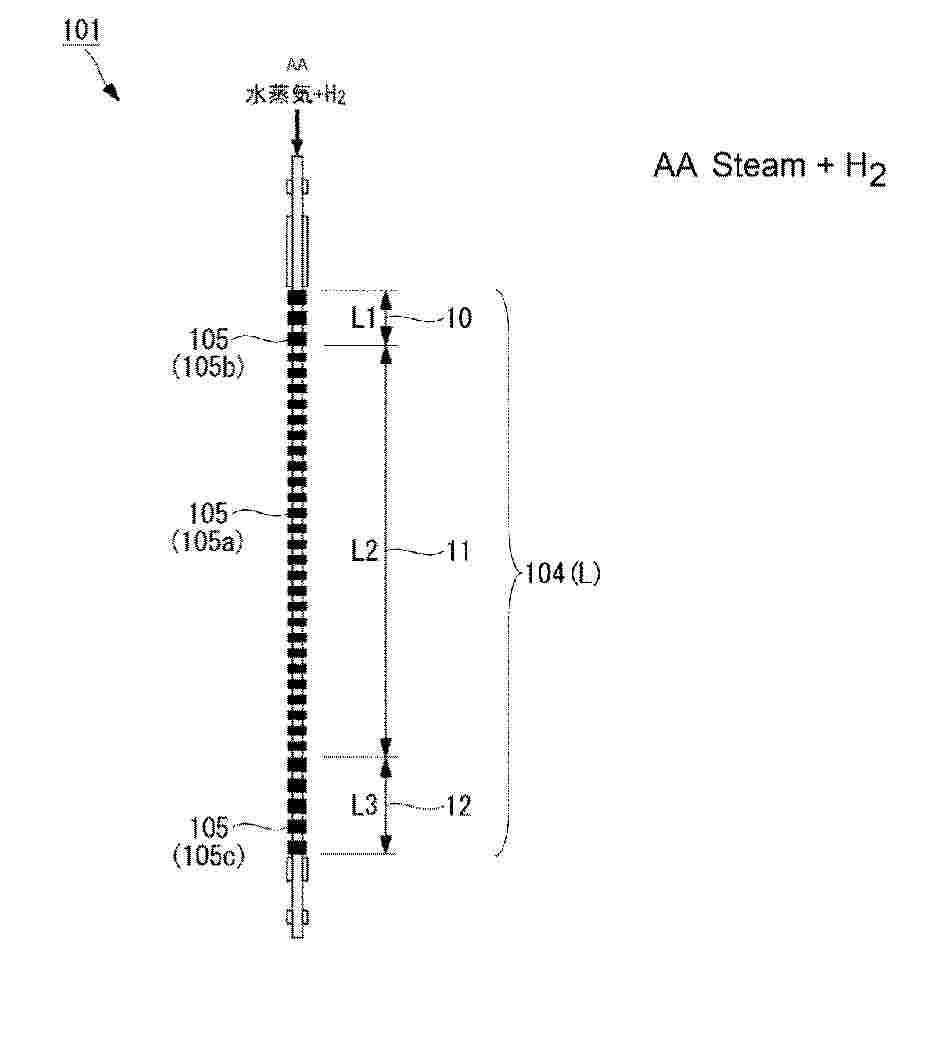
The purpose of the present disclosure is to provide an electrolytic cell stack capable of increasing the amount of product generated by electrolysis while suppressing the temperature rise of the cell stack. An electrolytic cell stack (101) according to the present disclosure comprises: an electrolysis unit cell (105) that has a hydrogen electrode containing Ni, an oxygen electrode, and a solid electrolyte membrane and is formed in the circumferential direction of a base tube; and an interconnector that electrically connects a plurality of electrolysis unit cells arranged in the axial direction of the base tube. When the distance between the ends of the oxygen electrode, oriented in the axial direction of the base tube, in each electrolysis unit cell is defined as the width W of the electrolysis unit cell, and the area on the base tube in which the plurality of electrolysis unit cells are arranged is divided into a first end portion (10), a central portion (11), and a second end portion (12) along the axial direction, the widths W1, W3 of the electrolysis single cells (105b, 105c) positioned in the first end portion and/or the second end portion is 1.5 to 3 times greater than the width W2 of the electrolysis unit cell (105a) positioned in the central portion.
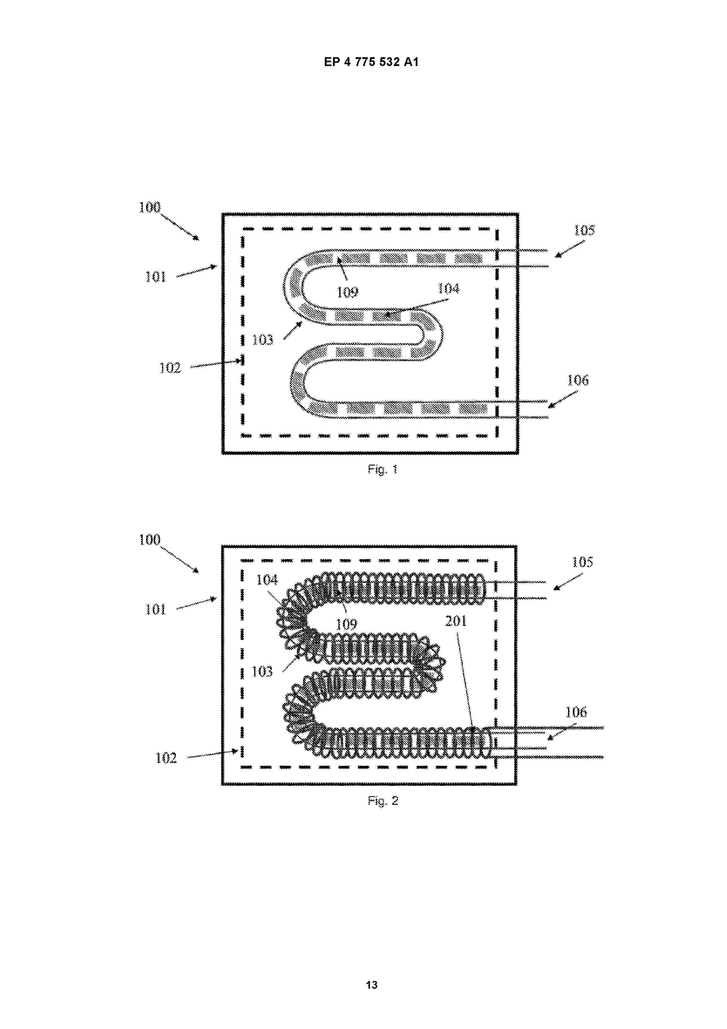
Resumen de: EP4775532A1
0001 (EN) The present invention relates to a method for producing hydrogen by means of thermochemical water dissociation cycles under (quasi-)isothermal conditions, wherein said method comprises arranging a large amount of active material (104) inside a reaction volume (109) of a reactor (103); heating the active material (104), reducing the active material (104) and generating oxygen in the reaction volume; evacuating the oxygen produced via a first evacuation path (111) of the outlet (106) of the reactor (103); injecting water into the reaction volume (109) of the reactor, oxidating the active material (104) and producing hydrogen; evacuating the hydrogen produced via a second evacuation path (112) of the outlet (106) of the device (100); and separating the evacuated hydrogen and remaining water. The invention further relates to a device for producing hydrogen.
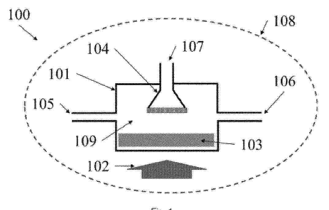
Resumen de: EP4775533A1
0001 (EN) The present invention relates to a method for obtaining hydrogen through water molecule dissociation using thermochemical reactions under (quasi-)isothermal conditions, which comprises the following steps: placing active material (103) in the reaction chamber (109) of a reactor (101); reducing the active material (103) by supplying heat; evacuating the oxygen produced through a first outlet (106); injecting water into the reaction chamber (109); oxidizing the active material (103), thereby producing hydrogen; filtering the hydrogen produced through a selective filter (104) during the oxidization of the active material (103); and evacuating the filtered hydrogen through a second outlet (107), thereby obtaining a flow of high-purity hydrogen. The invention also relates to a device for carrying out the method.
Nº publicación: EP4774432A1 15/07/2026
Solicitante:
SCHAEFFLER TECHNOLOGIES AG [DE]
Schaeffler Technologies AG & Co. KG
Resumen de: WO2025051333A1
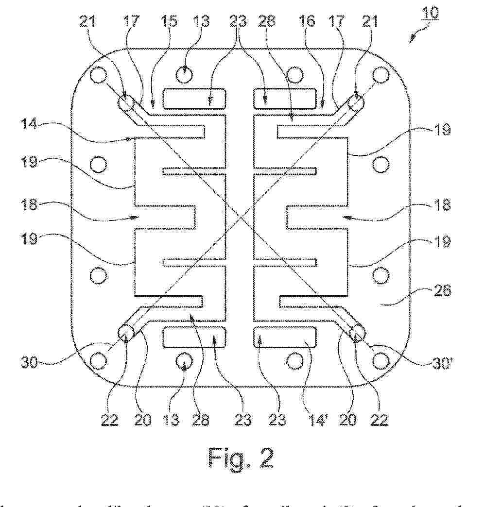
The invention relates to a plate-like element (10) of a cell stack (2) of an electrochemical system (1), having a first plate side (26), a second plate side (27), a plurality of openings (13, 21, 22, 23, 23') and a first structure (14) for forming a flow field for coolant and several further structures (14') for forming distributors for operating media on the first plate side (26). The structure (14) comprises a coolant conducting structure (15, 16) through which a first coolant path (15) and a second coolant path (16) arranged mirror-symmetrically thereto are formed, each of which have, starting from one of the openings (21), an elongate inflow portion (17), a centre portion (18) which starts from the inflow portion (17), fans out and describes at least one meandering bend (19), and an elongate outflow portion (20) which adjoins the centre potion (18) and is narrower than the centre portion (18). A longitudinal axis (30) of the inflow portion (17) of the first coolant path (15) matches a longitudinal axis (30) of the outflow portion (20) of the second coolant path (16), and a longitudinal axis (30') of the inflow portion (17) of the second coolant path (16) matches a longitudinal axis (30') of the outflow portion (20) of the first coolant path (15). The invention also relates to a cell stack (2) comprising a plurality of such plate-like elements (10) which are parallel to one another.
 BOPI
BOPI
 Sede Electrónica