Si deseas distinguir tus productos, servicios o ambos de los de otra empresa, es posible que necesites una marca o nombre comercial. Descubre qué son, en qué consiste su procedimiento de registro y qué implica.

Información sobre los plazos de presentación de solicitudes de transformación de marcas de la Unión Europea en marca nacional española. Más información


Si tienes un nuevo dispositivo, producto o procedimiento que resuelva un problema técnico o tenga una ventaja práctica, existen distintas formas de protegerlo en España y en otros países. Descubre cómo hacerlo.

¿Tu innovación reside en la estética, la ornamentación o la apariencia de tu producto? Protégela mediante un diseño industrial. Descubre qué derechos confiere el registro y cómo realizar la tramitación.

Las indicaciones geográficas protegen el nombre de un producto originario de una zona geográfica, a la cual le debe una determinada calidad, reputación u otra característica. Descubre qué son, en qué consiste su procedimiento de registro y qué beneficios conceden.

Las patentes publicadas en todo el mundo son una valiosa fuente de información científica, técnica y comercial.

Si eres emprendedor/a o una empresa y quieres potenciar y mejorar la rentabilidad de tu negocio protegiendo de forma adecuada los activos intangibles de tu organización, en este espacio encontrarás lo necesario.


 85
resultados
85
resultados
 Última actualización
24/04/2026 [06:58:00]
Última actualización
24/04/2026 [06:58:00]


 Resultados 25 a 50 de 85

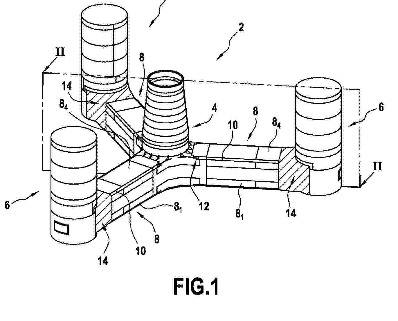
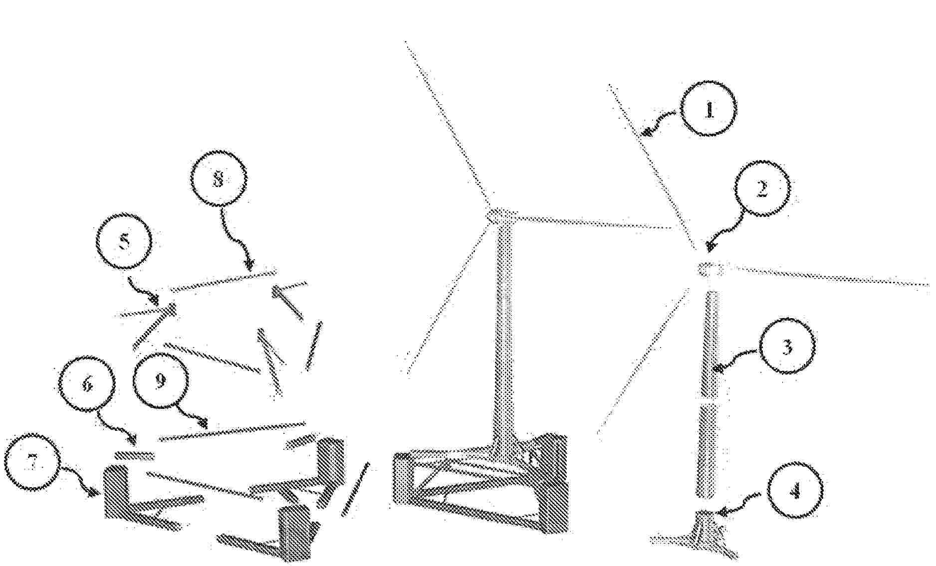
Resumen de: WO2024236128A1
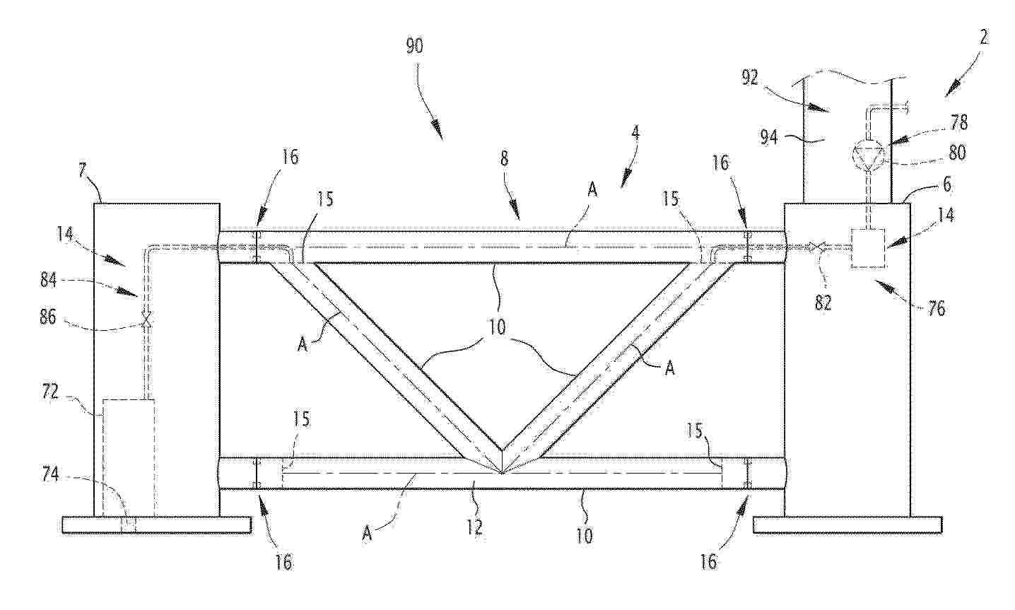
The floating offshore platform (2) comprises a support structure (4) having a beam (8) configured for extending between first and second structural elements (6, 7), the beam (8) being formed of several tubes (10) connected together and comprising a tank (12) delimited within at least two tubes (10) connected such that the individual internal volumes of said at least two tubes (10) are in fluid communication, and at least three connections (16) each configured for mechanically connecting an end of one tube (10) of the beam (8) to one of the first and second structural elements (7), wherein each connection (16) with the first structural element (6) is a bolted flange connection (16) and/or each connection (16) with the second structural element (7) is a bolted flange connection (16).

Resumen de: US20260077834A1
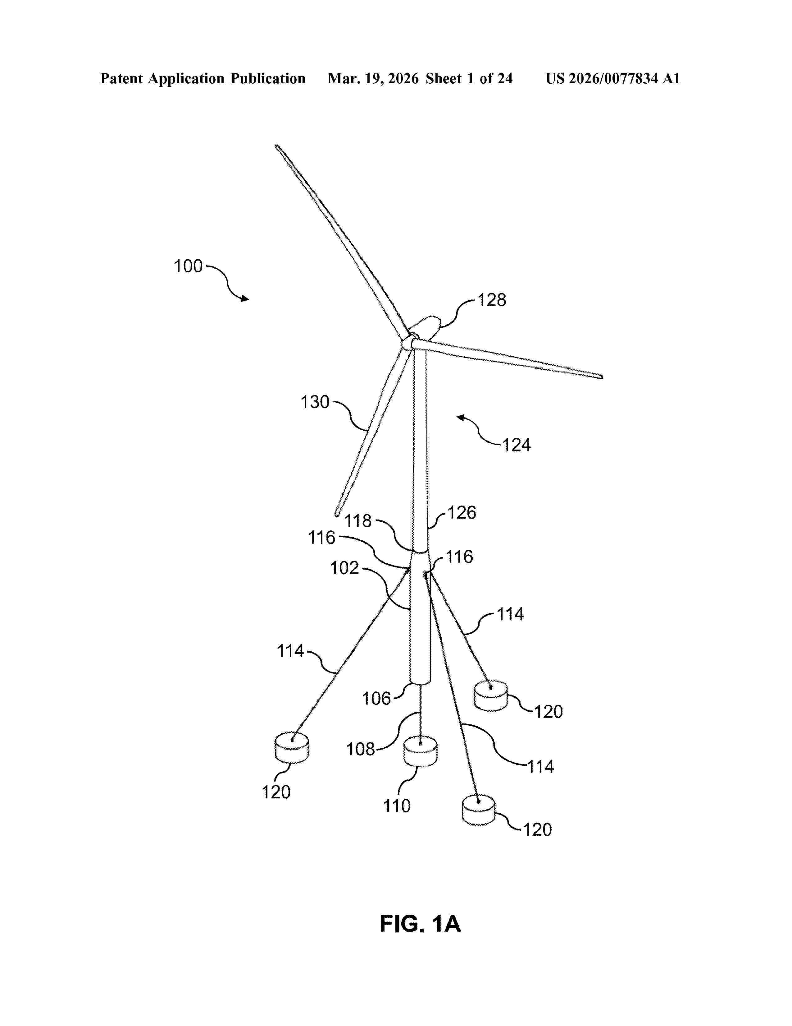
A buoyant offshore renewable energy system mounting having a buoyant spar and a plurality of mooring lines arranged to tether the spar to a bed of a body of water. The buoyant spar is positioned in the body of water at an operating depth. The plurality of mooring lines includes one or more first mooring lines affixed to the spar and arranged to engage the bed of the body of water. At least three further mooring lines are in communication with the spar between the top end and the bottom end, and a second end of each of the further mooring lines engage the bed of the body of water such that the further mooring lines are oriented diagonally at the operating depth. The first end of the spar is positioned above the surface, and the second end is positioned below the surface of the body of water.
Resumen de: WO2026058038A1
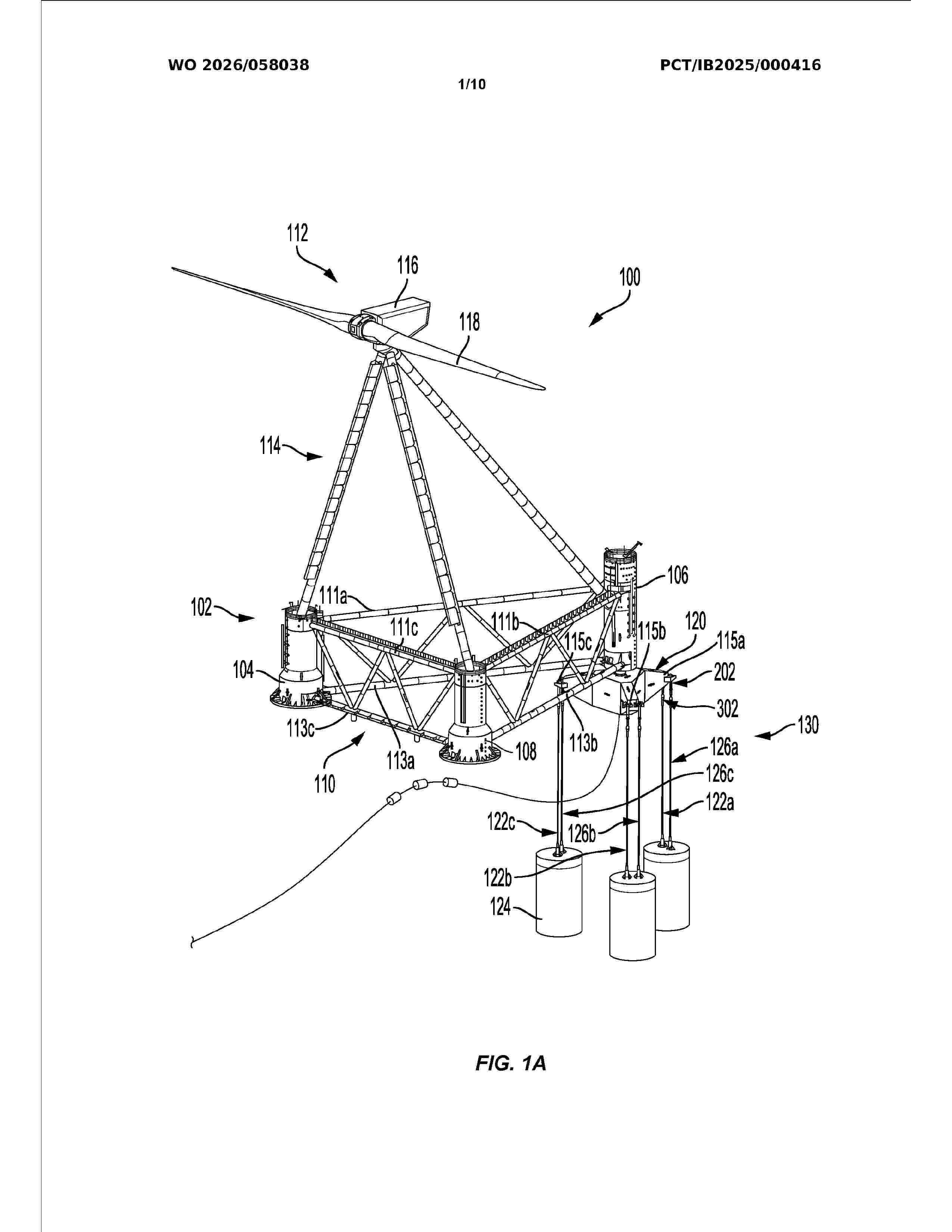
A tensioned leg floating platform mooring system and related methods may be used to secure the position of a floating platform. For example, the floating platform mooring system may include at least three fixed-length mooring lines coupled at different locations between a floating platform and one of one or more mooring piles. Additionally, the tensioned leg floating platform mooring system can include an adjustable-length mooring line coupled between the floating platform and one of the one or more mooring piles. The floating platform mooring system may further include a mooring line tension device coupled to the adjustable-length mooring line. The mooring line tension device may adjust a tension of the adjustable-length mooring line by adjusting a length of the adjustable-length mooring line in situ.
Resumen de: WO2026059486A1
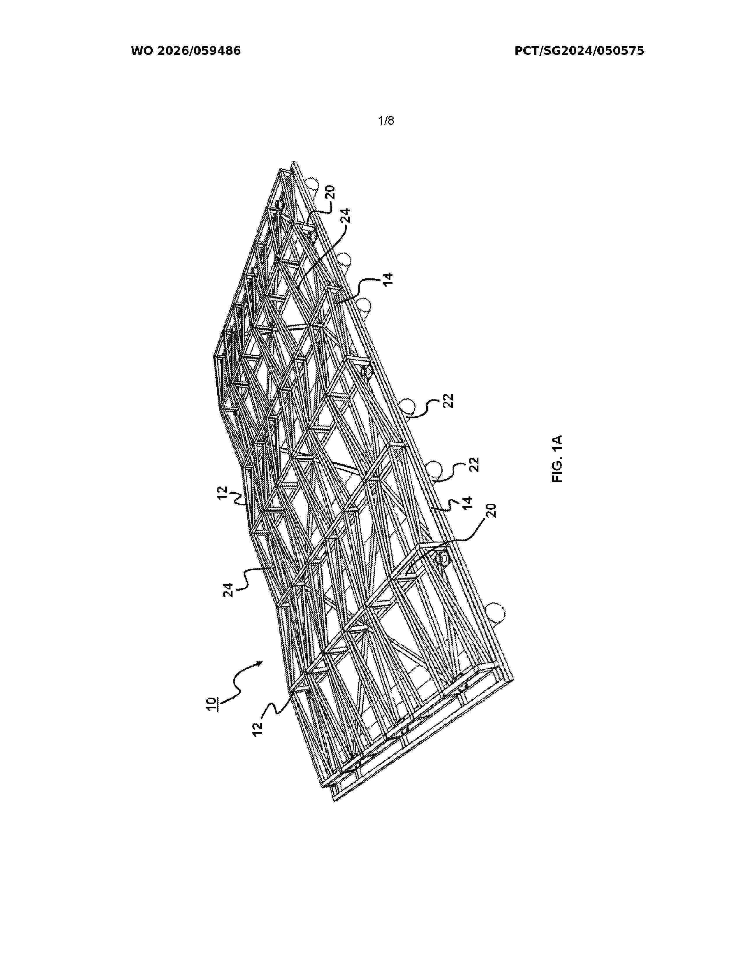
An offshore platform (10) for energy farming is provided. The offshore platform (10) includes a plurality of first beams (12) arranged to receive a plurality of solar panels, the first beams (12) defining a first layer (16), a plurality of second beams (14) arranged 5 to define a second layer (18), and a plurality of posts (20) separating the first and second layers (16, 18). A plurality of hollow pipes (22) is attached to a base of the second layer (18), the hollow pipes (22) extending across the second layer (18).
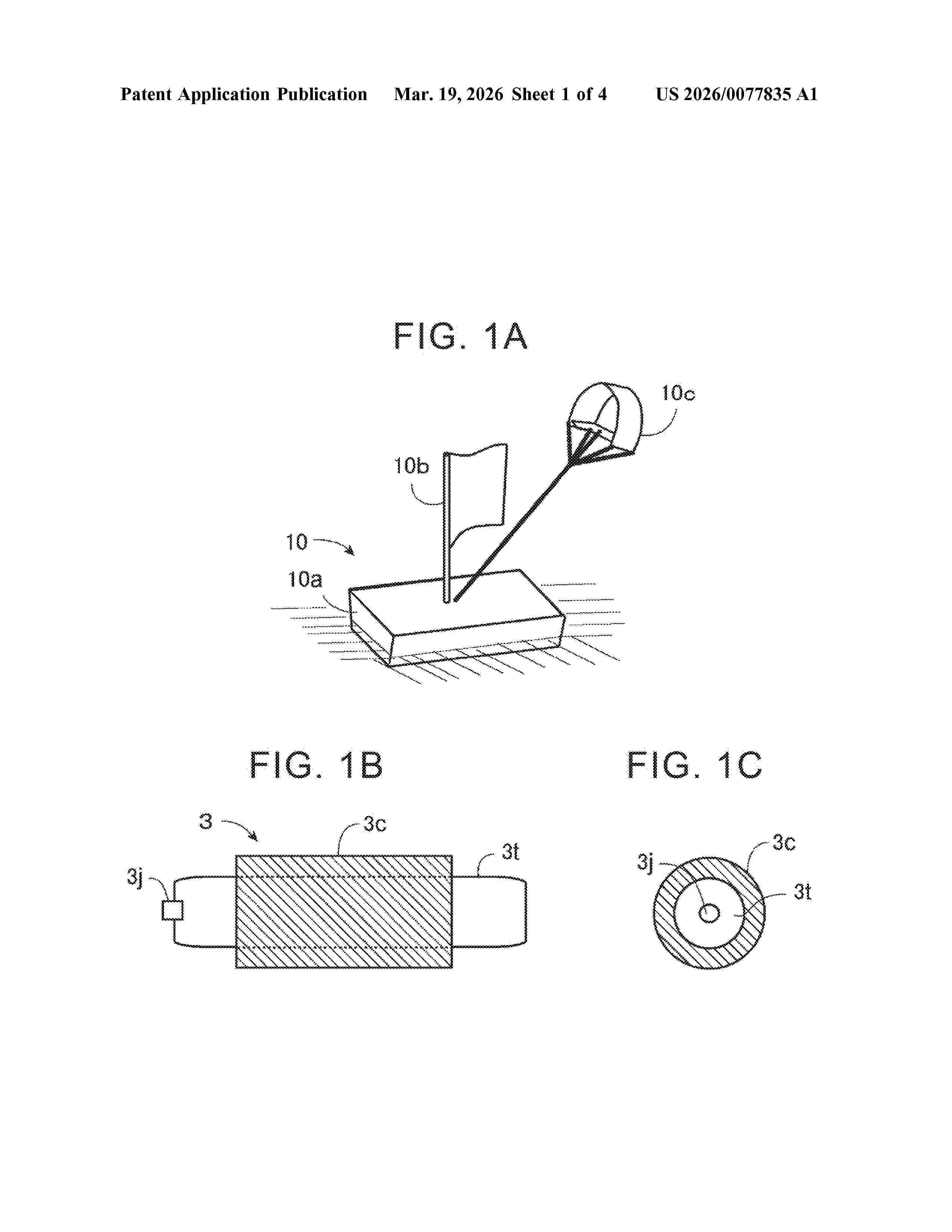
Resumen de: US20260077835A1
A method of transferring a storage medium loaded on a power generation float from a float that generates electricity on the ocean to a transport vessel on the ocean includes a first process of fixing the power generation float to the transport vessel so that a height of a loading place of the storage medium of the power generation float is higher than a height of a storage place of the storage medium of the transport vessel, a second process of forming a first path in which the storage medium can move between the loading place of the storage medium of the power generation float and the storage place of the storage medium of the transport vessel, and a third process of moving the storage medium from the loading place of the power generation float to the storage place of the transport vessel by gravity through the first path.
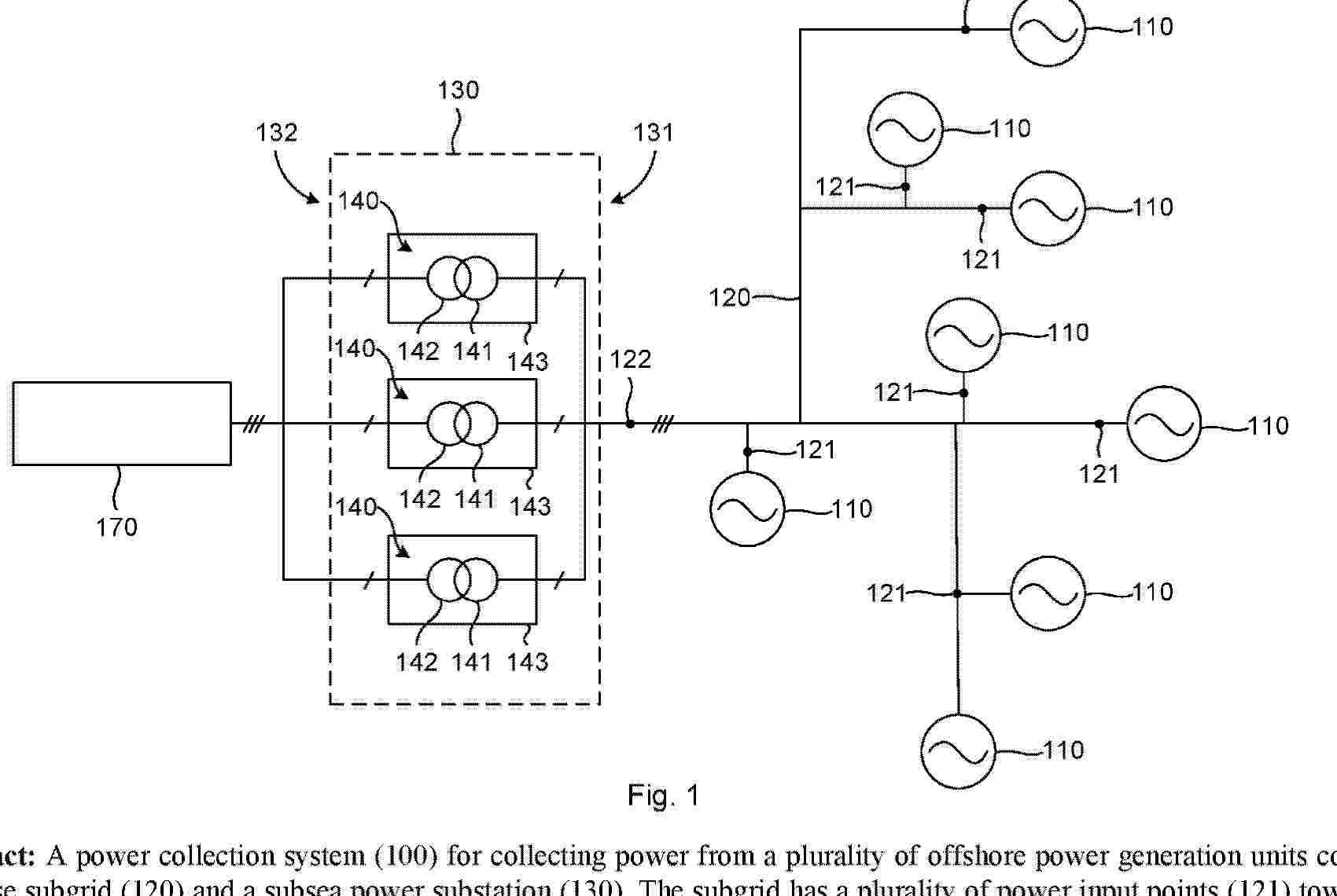
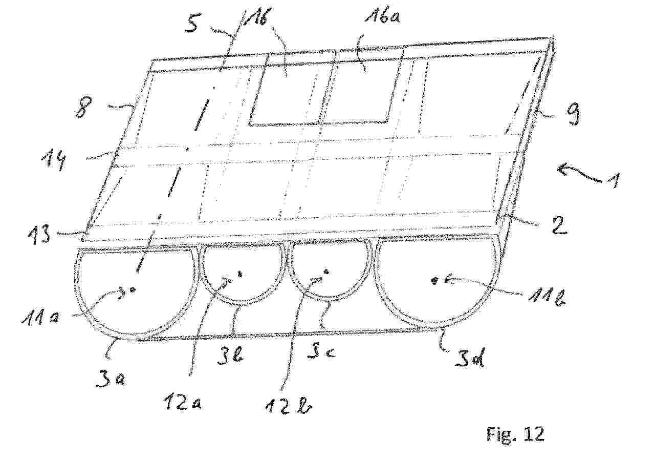
Resumen de: AU2024330912A1
A power collection system (100) for collecting power from a plurality of offshore power generation units comprises a three-phase subgrid (120) and a subsea power substation (130). The subgrid has a plurality of power input points (121) towards the power generation units and a shared three-phase power output point (122). The power substation (130) is connected to the power output point, and its secondary side (132) is arranged to be connected to a power consumer (170). The power substation shall comprise three one-phase transformers (140), which are contained in respective housings (143), wherein each housing is arranged to rest on the seabed and to be liftable to the sea surface separately from the other housings. Each phase of the power output point is connected to a primary side (141) of a corresponding one of the one-phase transformers.
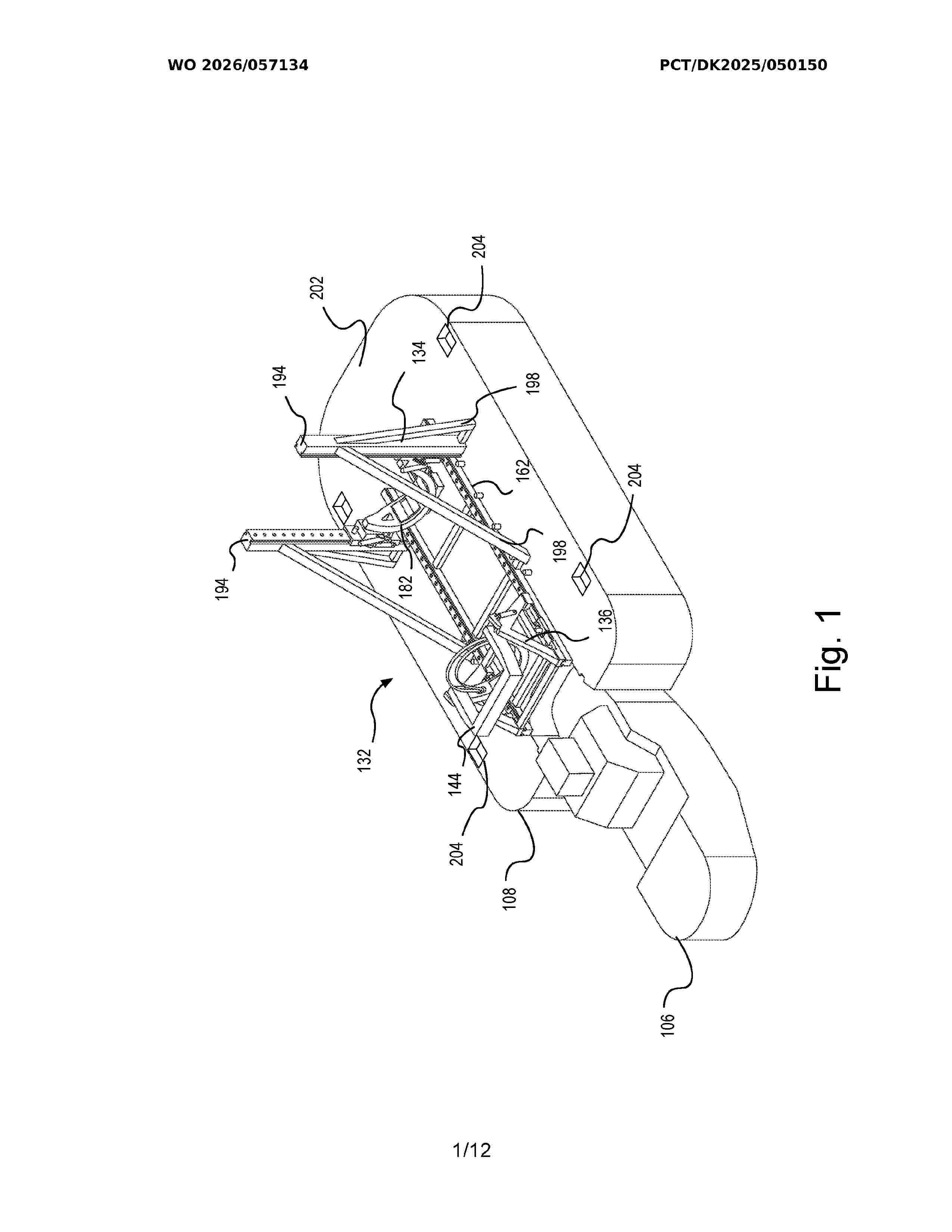
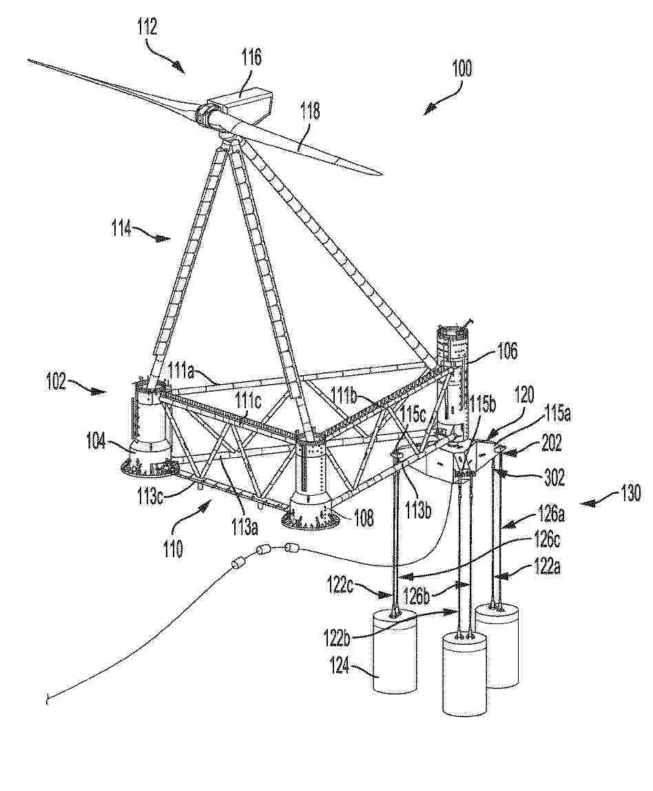
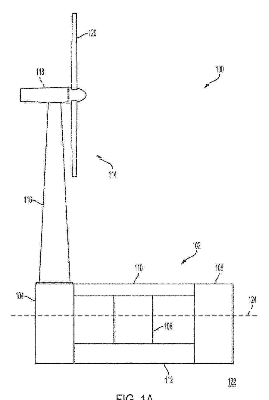
Resumen de: WO2026057134A1
An offshore installation system (100) for handling a monopile comprises a monopile transportation vessel (102) configured to transport the monopile in a horizontal position. A monopile handling mechanism (132) is mounted on the transportation vessel (102) and is configured to secure the monopile during transportation and move it to an inclined position. The system also includes an offshore installation vessel with a hull (122) and a plurality of moveable legs (126), wherein the hull is positioned out of the water when the moveable legs engage the seafloor. A push down stabilising mechanism (130) is mounted on the offshore installation vessel and is configured to apply a downward force on the monopile transportation vessel to increase its buoyancy force when positioned underneath the hull, stabilising the monopile transportation vessel and the inclined monopile with respect to the offshore installation vessel.
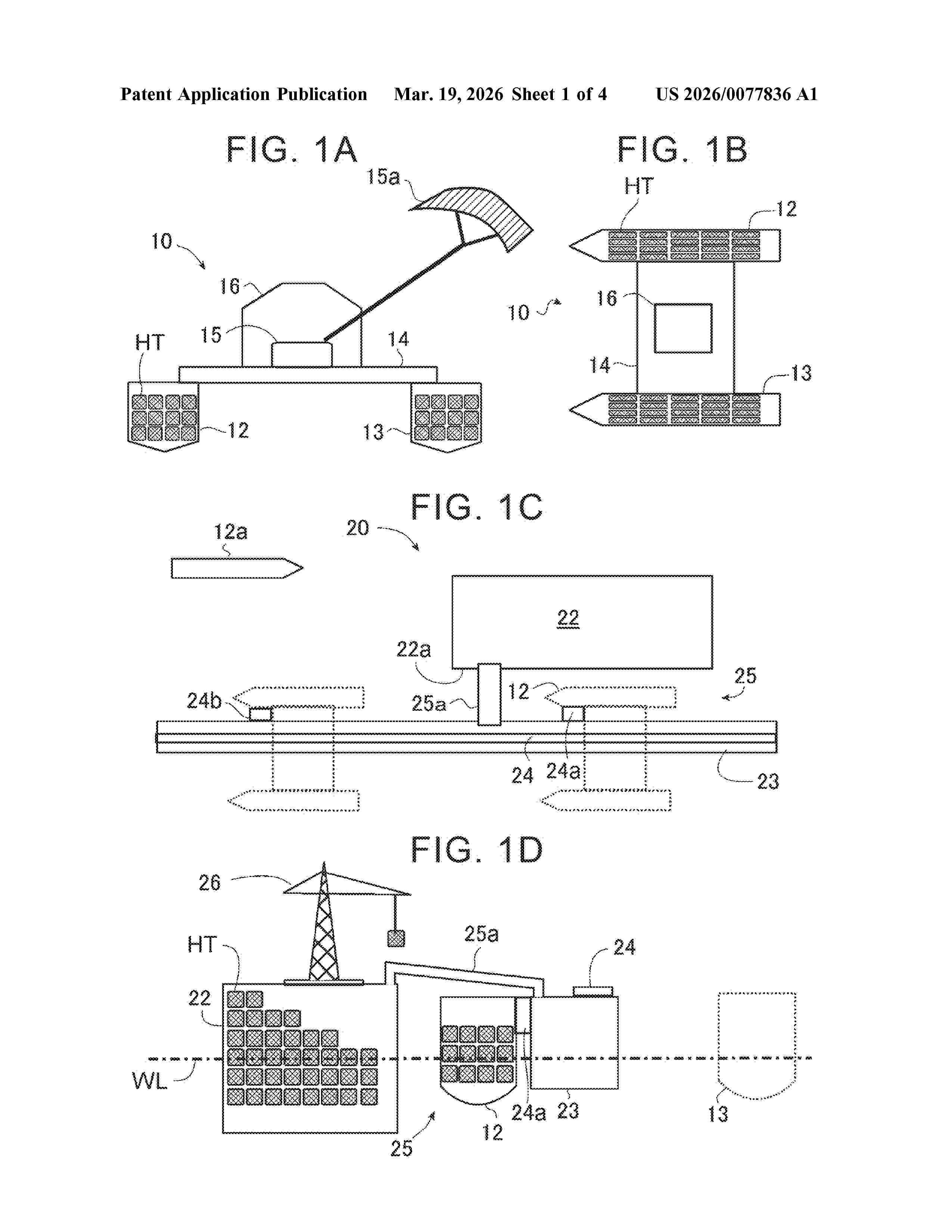
Resumen de: US20260077836A1
In a method for transferring a storage medium of power generation energy loaded by a power generation float to a collection base, a power generation float is connected to both sides of a deck part, a power generation float is moved to a collection base, a deck part straddles a long bank projecting on a water surface along a water channel through which a hull can pass along a quay wall of a collection base, a power generation float is anchored in a state where one of the hulls enters a water channel, a hull on at least one side of the deck part is separated from the deck part, and a storage medium capable of storing energy is connected on a side where the hull of the deck part is separated, and the float leaves with the hulls connected to both sides of the deck part.
Resumen de: EP4711257A1
A tensioned leg floating platform mooring system and related methods may be used to secure the position of a floating platform. For example, the floating platform mooring system may include at least three fixed-length mooring lines coupled at different locations between a floating platform and one of one or more mooring piles. Additionally, the tensioned leg floating platform mooring system can include an adjustable-length mooring line coupled between the floating platform and one of the one or more mooring piles. The floating platform mooring system may further include a mooring line tension device coupled to the adjustable-length mooring line. The mooring line tension device may adjust a tension of the adjustable-length mooring line by adjusting a length of the adjustable-length mooring line in situ.
Resumen de: EP4711258A1
A floating quay includes a deck relocatable in a body of water adjacent a stationary quay to receive one or more floating units. The deck includes a gradual slope from an elevation of a surface of the stationary quay to a submerged position below a water level of a water surface of the body of water. The floating quay further includes an elevator system positionable to raise and lower at least a portion the deck to receive the one or more floating units from the stationary quay and to deploy the one or more floating units into the body of water using the gradual slope of the deck.
Resumen de: AU2024353216A1
The invention relates to a method for the active and centralised ballasting of a semi-submersible float (2) for an offshore wind turbine, the float comprising at least four columns, including a central column (4) and three outer columns (6), which are connected to the central column by lower arms forming pontoons (8), wherein the method comprises the controlled and centralised displacement of a ballast fluid between sealed compartments (14) formed inside each pontoon (8), so as to modify the inclination thereof. The invention also relates to a semi-submersible float for an offshore wind turbine with active and centralised ballasting.
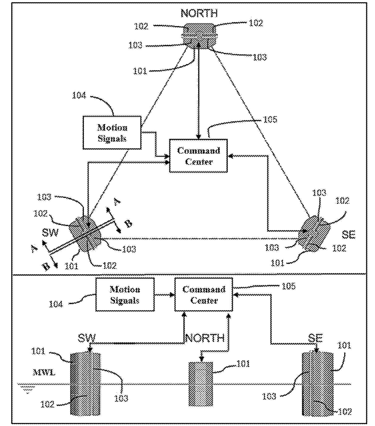
Resumen de: US20260070634A1
The method for counterbalancing the mean inclination of a Floating Offshore Wind Turbine (FOWT) platform is designed to be simple, efficient, and highly responsive. It employs short-distance piping to enable swift and effective pump-in and pump-out operations within the same column, allowing for precise and independent control of ballast operation. This strategy is not only cost-efficient but also supports remote operation, facilitating rapid adjustments for both normal and abnormal conditions. Furthermore, the method incorporates redundancy in the counterbalancing systems, significantly boosting the overall reliability and ensuring consistent and effective ballast management for the platform.
Resumen de: DE102024136925A1
Schwimmende Windenergieanlage (10) mit einem schwimmenden Fundament, das eine Mehrzahl von sich von einem Zentralelement (20) erstreckenden Armen (30) aufweist, einem auf dem Zentralelement (20) des schwimmenden Fundaments angeordneten Turm (40) mit wenigstens einer auf dem Turm (40) angeordneten mit diesem drehfest verbundenen, einen Rotor aufweisenden Energiewandlungseinheit, und einem das Fundament mit der wenigstens einen Energiewandlungseinheit verbindendem Seilsystem (50) zur Einleitung der auf den Turm (40) und die wenigstens eine Energiewandlungseinheit wirkenden Schubkräfte in das Fundament, wobei das Seilsystem (50) Vorspannungen aufweist, deren Beträge jeweils größer als im Betrieb der Windenergieanlage zu erwartende, der jeweiligen Vorspannung entgegenwirkende Lasten sind, dadurch gekennzeichnet, dass der Turm (40) in einem am Zentralelement (20) angeordneten axialen Pendelgleitlager (60) gelagert ist.
Resumen de: AU2024351711A1
The invention relates to a method for the active and individualised ballasting of a semi-submersible float (2) for an offshore wind turbine, the float comprising at least four columns, including a central column (4) and three outer columns (6), which are connected to the central column by lower arms forming pontoons (8), wherein the method comprises, for each pontoon, the individualised and controlled displacement of a ballast fluid between at least two separate sealed compartments (14, 16) located inside an assembly formed by the pontoon and the associated outer column, so as to modify the inclination of the float. The invention also relates to a semi-submersible float for an offshore wind turbine with active and individualised ballasting.
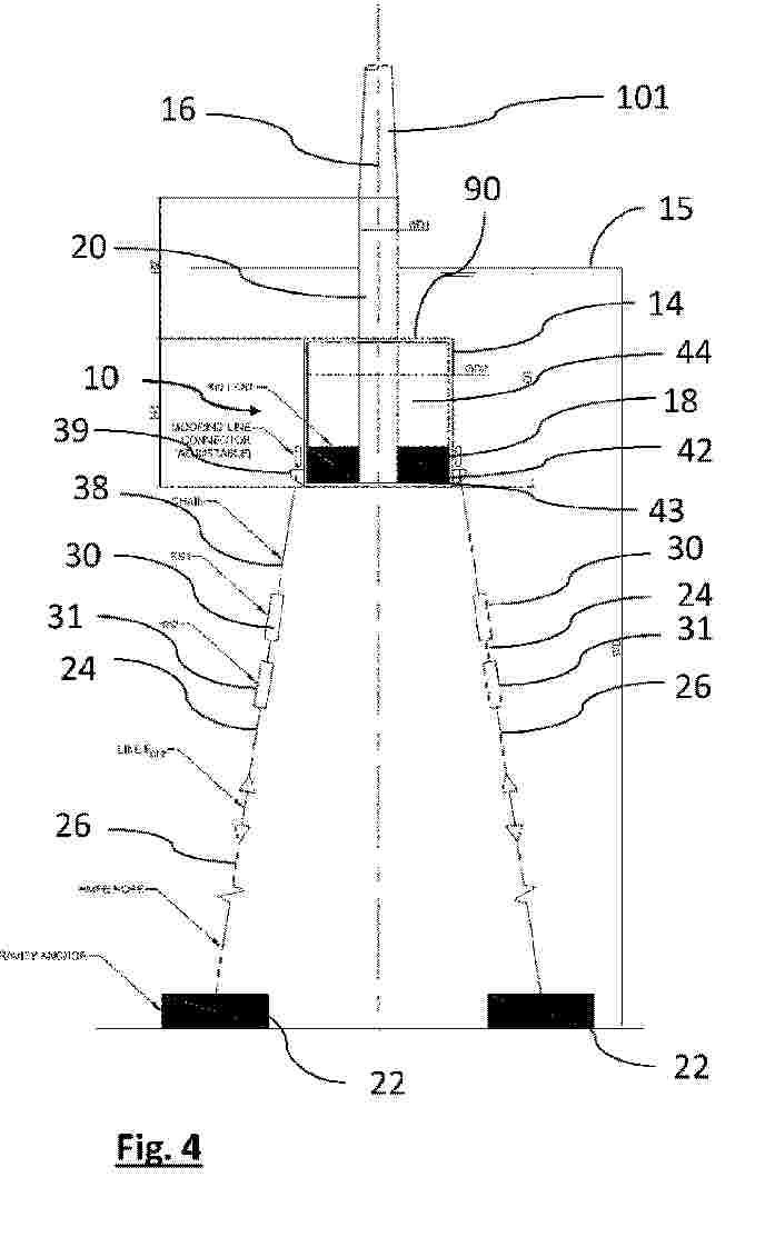
Resumen de: EP4707152A1
Proposed is a mooring system, including a floating unit for floating on the sea surface, a mooring anchor installed on the seabed, a weight unit positioned underwater between the floating unit and the mooring anchor, a plurality of mooring cables each having a closed curve shape for mooring the floating unit, wherein each mooring cable includes a first portion whose middle lower part is caught in a mooring-cable catching part of the weight unit, a second portion which passes through a vertical penetration passage of the weight unit and whose middle lower part is caught in a mooring-cable catching part of the mooring anchor, and a third portion which passes through a vertical penetration passage of the floating unit and is connected to the first portion and the second portion and whose middle upper part is caught in a mooring-cable catching part of the floating unit provided in the floating unit.
Resumen de: AU2024263697A1
The invention relates to a mooring arrangement for mooring a floating unit to the seabed, the mooring arrangement comprises multiple mooring clusters each connectable to a floating unit and an anchor adapted for the seabed, wherein at least one mooring cluster comprises at least two mooring lines.
Resumen de: BE1032839A1
L'invention divulgue un procédé de contrôle d'un système d'énergie éolienne en mer, se rapportant au domaine technique du contrôle de l'énergie éolienne en mer. Ledit système d'énergie éolienne en mer comprend un groupe éolien, un convertisseur, des capteurs de vibration et de contrainte ainsi qu'un contrôleur, et vise à résoudre le problème technique consistant à efficacement inhiber les charges structurelles clés tout en garantissant la sortie de puissance. Les points clés de sa solution technique sont les suivants: obtenir une séquence de vitesse de vent de prévision à l'avant par le biais d'un lidar de nacelle, tout en collectant en temps réel les données de charges de la tour et des pales; construire un modèle d'espace d'état paramétré, et utiliser l'algorithme de filtre de Kalman sans trace pour réaliser l'identification en ligne et l'estimation d'état des paramètres aérodynamiques et de la dynamique non modélisée; dans chaque période de contrôle, avec le suivi de puissance et l'inhibition de charges comme objectifs multiobjectifs, résoudre le problème de contrôle optimal à horizon fini sur la base du modèle mis à jour et de la séquence de vitesse de vent de prévision; enfin, analyser et exécuter la commande incrémentale optimale de l'angle de calage et la commande incrémentale optimale du couple du générateur. Ce procédé est principalement utilisé pour améliorer la durée de fonctionnement et la stabilité des group
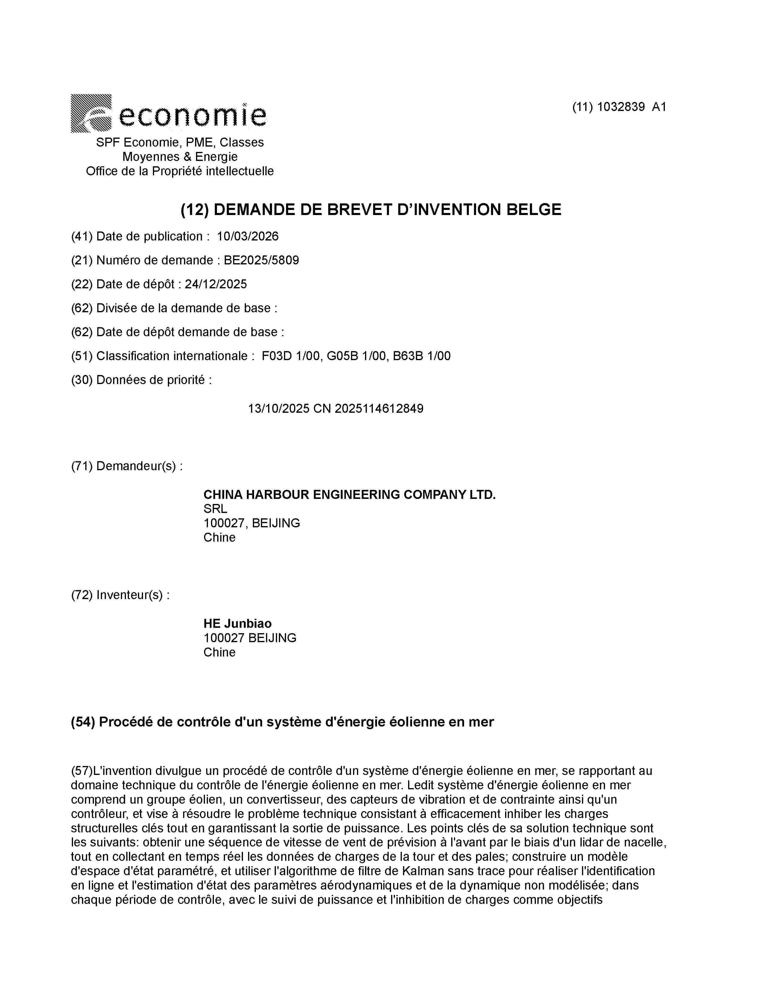
Resumen de: WO2026047105A1
The invention relates to a floating functional unit, in particular a floating platform (1) or a watercraft, comprising a deck structure (2) and one or more buoyancy bodies (3a, 3b, 3c, 3d), one or more of the buoyancy bodies each comprising a rotor blade (4) or a part, in particular a longitudinal portion, of a rotor blade of a wind turbine. The invention further relates to such a buoyancy body and to a method for the production thereof from a rotor blade.
Resumen de: US20260063101A1
A wave energy-based reef sustainable device integrated with an offshore wind turbine is provided. The wave energy-based reef sustainable device integrated with an offshore wind turbine can be put into a seabed, is configured to connect with a floating wind turbine, and includes a base is configured as a fish reef, an anchoring device configured to connect with the floating wind turbine, and includes plural rings with a luminous coating and at least one mooring system or cable with a luminous layer. The rings swing and/or rotate due to the pull of the floating wind turbine and present a flashing effect to attract fish. The mooring system or cable with the luminous layer provides a warning effect, a lighting device configured to emit light to attract fish, and a green energy device configured to convert a green energy into an electrical energy, which is provided to the lighting device.
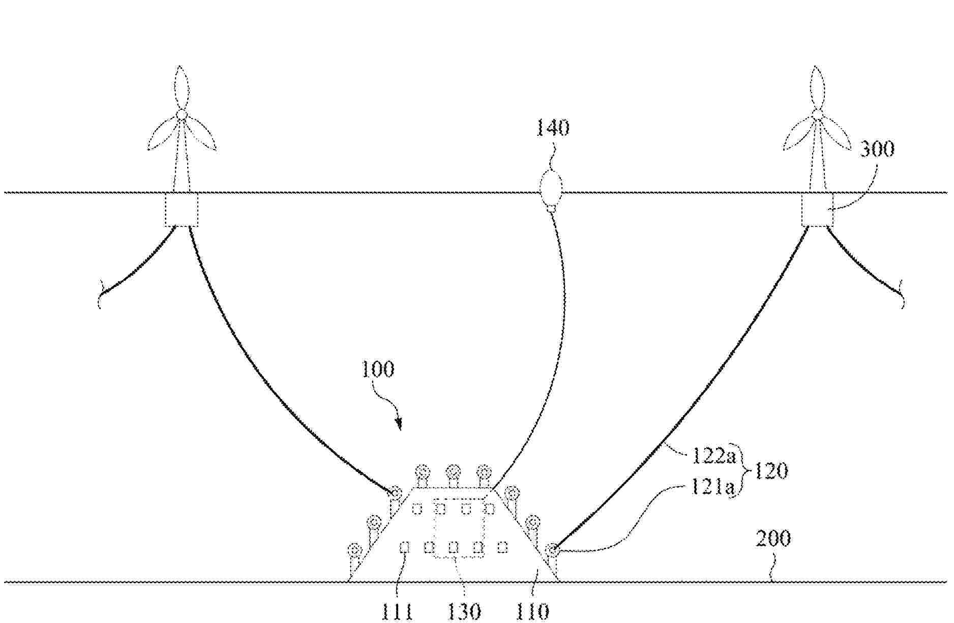
Resumen de: AU2024327326A1
Method of forming a tube element for use as a longitudinal section of a brace for a truss structure of a floatable offshore support structure for a wind turbine, comprising: providing four elongate flat steel plates each extending along a longitudinal direction and having two opposite lateral edges; deforming each plate such that, along the longitudinal direction, a transverse shape of the plate smoothly transitions between a rectilinear shape and an arcuate shape; and forming the tube element by interconnecting the four deformed plates along their lateral edges. The interconnected plates each form a respective circumferential section of the tube element, wherein along the longitudinal direction, a transverse shape of the tube element smoothly transitions from a circular shape to a rectangular shape. The tube element may connect a cylindrical further tube element of the brace with a further part of the floatable offshore support structure.
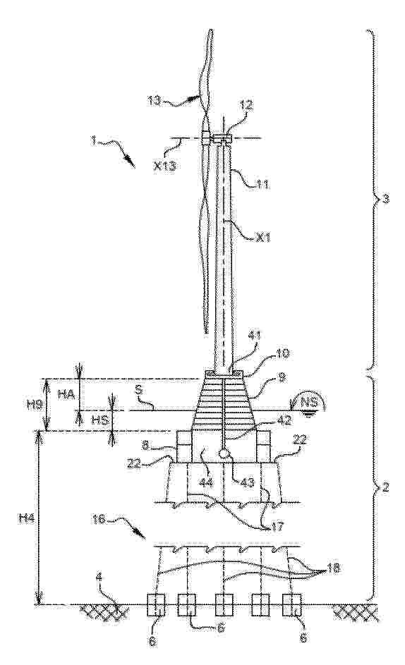
Resumen de: WO2026047260A1
The present invention relates to a floating wind turbine generator (WTG) foundation for a floating WTG system, the floating WTG foundation comprising: a floater having a generally cylindrical shape, wherein the floater defines a vertical axis, the floater comprising ballast at a lower end thereof, an upper projection extending upward from the floater, the upper projection having a smaller cross-section than the floater, at least three anchors which are connected to the seabed, at least three tendon assemblies, each tendon assembly extending between one of the anchors and a respective mounting position on the floater.
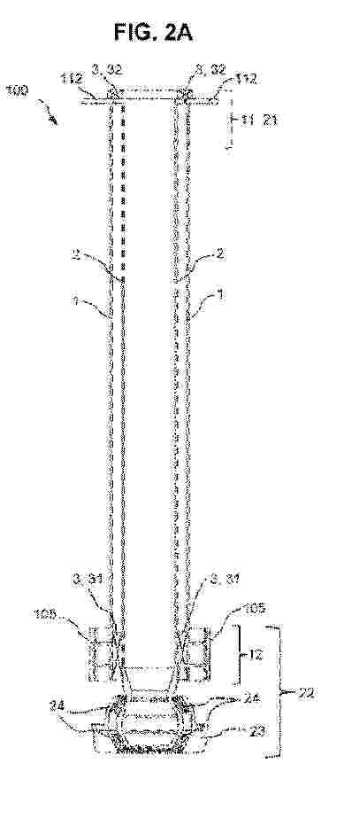
Resumen de: WO2026047092A1
A turret connecting module (100) for being selectively inserted in an operating position (O) within a weathervaning floating offshore structure (200) of a wind turbine (202) for connecting said weathervaning floating offshore structure (200) to a pre-laid mooring system (300), the turret connecting module (100) comprising: an external trunk element (1) configured to be attached to the weathervaning floating offshore structure (200); an internal shaft element (2) configured to be arranged within the external trunk element (1), and comprising a base portion (22) configured to be coupled to the pre-laid mooring system (300); and a bearing system (3) comprising at least one bearing (31, 32) configured to connect the external trunk element (1) to the internal shaft element (2) such that the external trunk element (1) is allowed to weathervane together with the weathervaning floating offshore structure (200) relative to the internal shaft element (2) and the prelaid mooring system (300).
Resumen de: US20260063108A1
A floating structure foundation for a wind turbine features several improvements, including a transition assembly that supports the wind turbine generator (WTG) and tower centrally, transferring loads to primary structural components to maximize efficiency. Its highly modular design allows for flexible construction and scalability, with each component built independently for easier adaptation to different project requirements and site conditions. This modularity supports efficient dry transport, enabling multiple modules to be shipped simultaneously on various vessels. The foundation offers a simplified design with accelerated construction, rapid assembly, and installation.
Resumen de: CN121001923A
The invention relates to a floating platform (2), the arrangement of anchoring ribs (17, 18) of which makes it possible to improve stability, in particular for a platform of a wind turbine (2). The invention also relates to a method of assembling such a platform and a wind turbine thereof, and to a method of anchoring such a platform at sea.
Nº publicación: US20260055756A1 26/02/2026
Solicitante:
WANG YONGHUA [US]
Wang Yonghua
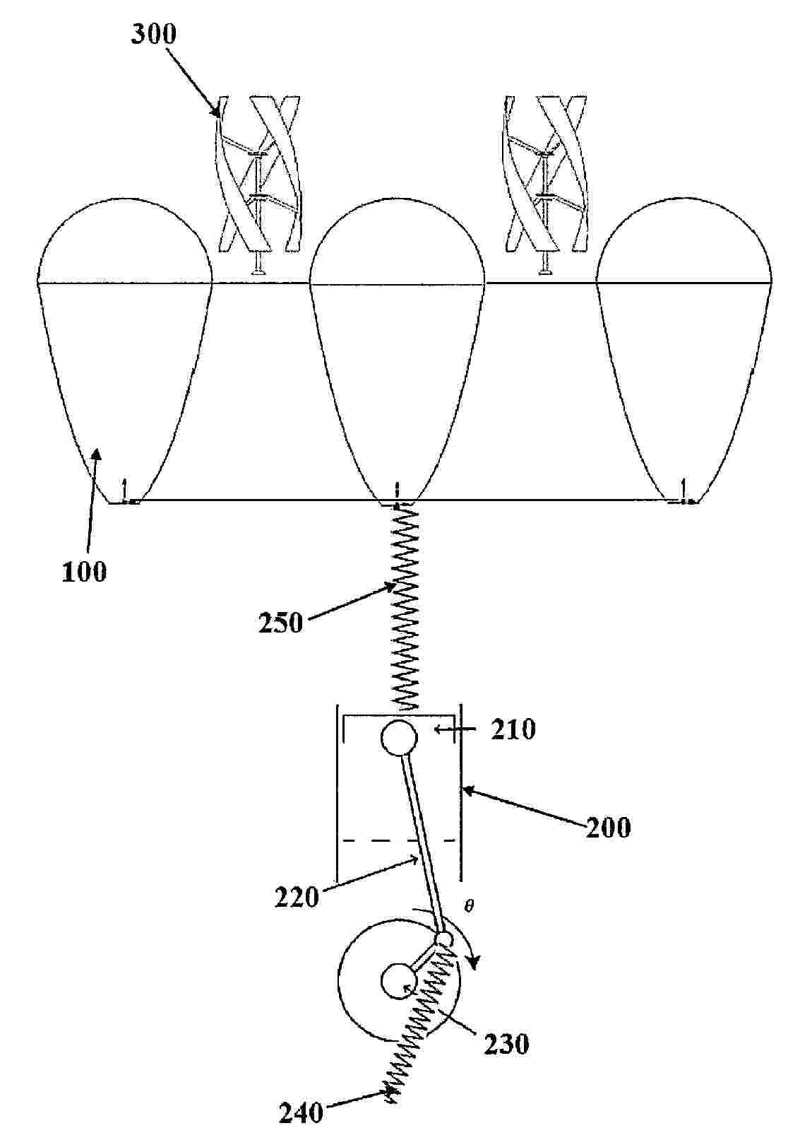
Resumen de: US20260055756A1
A combined stationary solar CSP, wave motion, and wind power generation and fresh water production system that deploys close structure non-imaging non-tracking solar concentrator array as buoy for wave motion converter system and floating platform for wind mills comprises a divergent Fresnel lens and non-imaging concentrator enabled non-imaging non-tracking solar concentrator based hybrid solar thermal and photovoltaic CSP system, a wave energy converter system, and a vertical axis wind energy system. Wherein, the stationary solar CSP system realizes ultra-high efficiency through solar thermal and photovoltaic cogeneration, substantially-low cost through stationary high concentration ratio concentration, and super-stable power generation through electrothermal energy storage. The system produces fresh water through thermal power generation and uses swappable battery modules to address power transportation and utilization issues.
 BOPI
BOPI
 Sede Electrónica