Si deseas distinguir tus productos, servicios o ambos de los de otra empresa, es posible que necesites una marca o nombre comercial. Descubre qué son, en qué consiste su procedimiento de registro y qué implica.

Información sobre los plazos de presentación de solicitudes de transformación de marcas de la Unión Europea en marca nacional española. Más información


Si tienes un nuevo dispositivo, producto o procedimiento que resuelva un problema técnico o tenga una ventaja práctica, existen distintas formas de protegerlo en España y en otros países. Descubre cómo hacerlo.

¿Tu innovación reside en la estética, la ornamentación o la apariencia de tu producto? Protégela mediante un diseño industrial. Descubre qué derechos confiere el registro y cómo realizar la tramitación.

Las indicaciones geográficas protegen el nombre de un producto originario de una zona geográfica, a la cual le debe una determinada calidad, reputación u otra característica. Descubre qué son, en qué consiste su procedimiento de registro y qué beneficios conceden.

Las patentes publicadas en todo el mundo son una valiosa fuente de información científica, técnica y comercial.

Si eres emprendedor/a o una empresa y quieres potenciar y mejorar la rentabilidad de tu negocio protegiendo de forma adecuada los activos intangibles de tu organización, en este espacio encontrarás lo necesario.


 789
resultados
789
resultados
 Última actualización
15/09/2026 [08:08:00]
Última actualización
15/09/2026 [08:08:00]


 Resultados 200 a 225 de 789

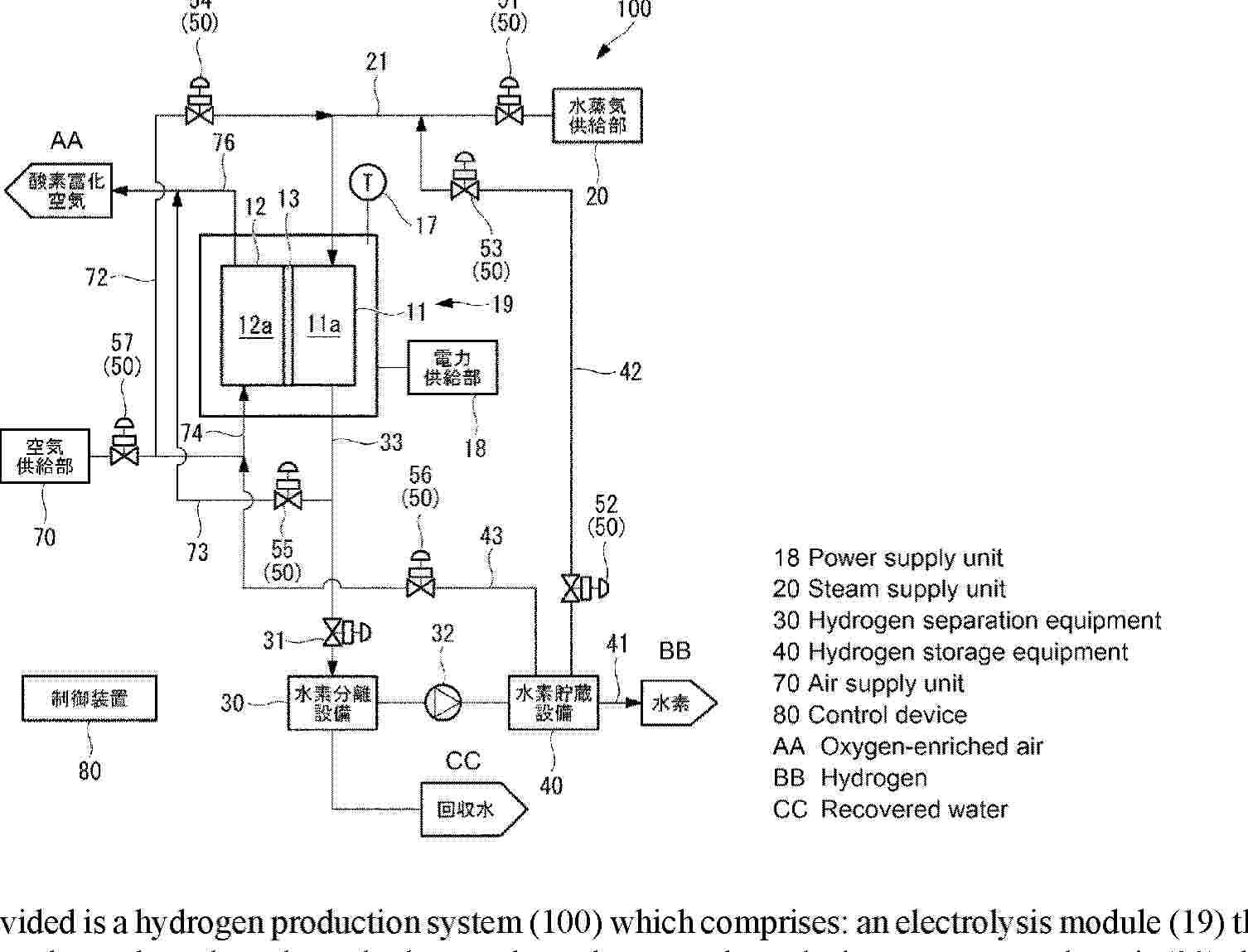
Resumen de: AU2024424555A1
Provided is a hydrogen production system (100) which comprises: an electrolysis module (19) that supplies steam to a hydrogen electrode and produces hydrogen through steam electrolysis; a steam supply unit (20) that supplies steam to a hydrogen electrode (11); an air supply unit (70) that supplies air to an oxygen electrode (12); a hydrogen supply pipe (43) that supplies hydrogen to the oxygen electrode (12); a power supply unit (18) that supplies power to the electrolysis module (19); and a control device (80) that controls the hydrogen production system (100). The control device (80) controls the power supply unit (18) so as to start supplying power to the electrolysis module (19) in response to the temperature of the electrolysis module (19) exceeding Temp4 that is lower than the ignition temperature of hydrogen.

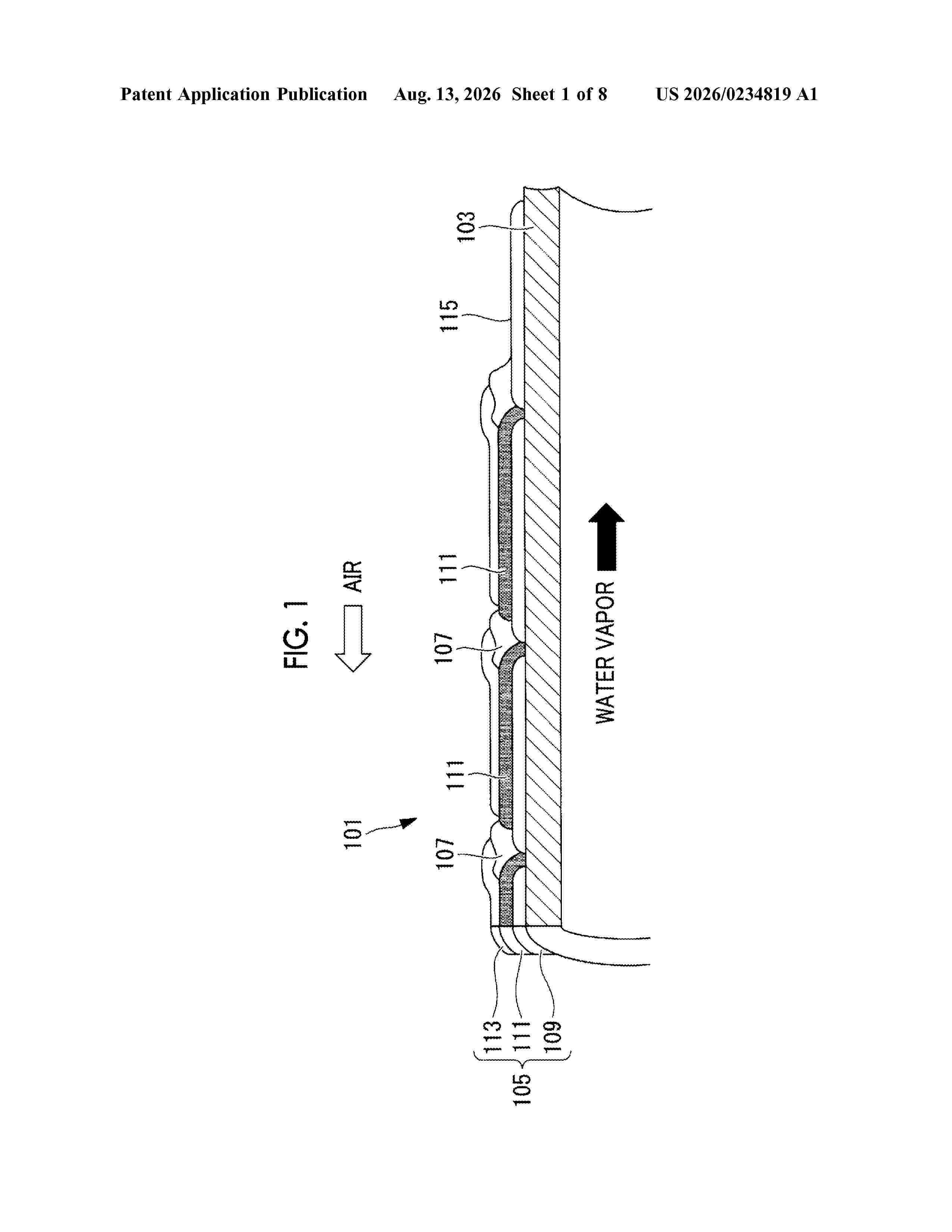
Resumen de: US20260234819A1
Provided is an electrolysis system including an electrolysis module; a water vapor supply system that supplies water vapor to a hydrogen electrode; a hydrogen recovery system that recovers hydrogen-enriched water vapor; an air supply system that supplies air to an oxygen electrode; an oxygen recovery system that recovers exhaust air; a hydrogen-enriched water vapor release system that releases hydrogen-enriched water vapor from the hydrogen recovery system into the atmosphere; an exhaust air release system that releases exhaust air from the oxygen recovery system into the atmosphere; a hydrogen-enriched water vapor discharge valve disposed in the hydrogen-enriched water vapor discharge system; and an exhaust air discharge valve disposed in the exhaust air discharge system, wherein the opening degrees of the hydrogen-enriched water vapor discharge valve and the exhaust air discharge valve are controlled to be adjustable when the electrolytic module is stopped.
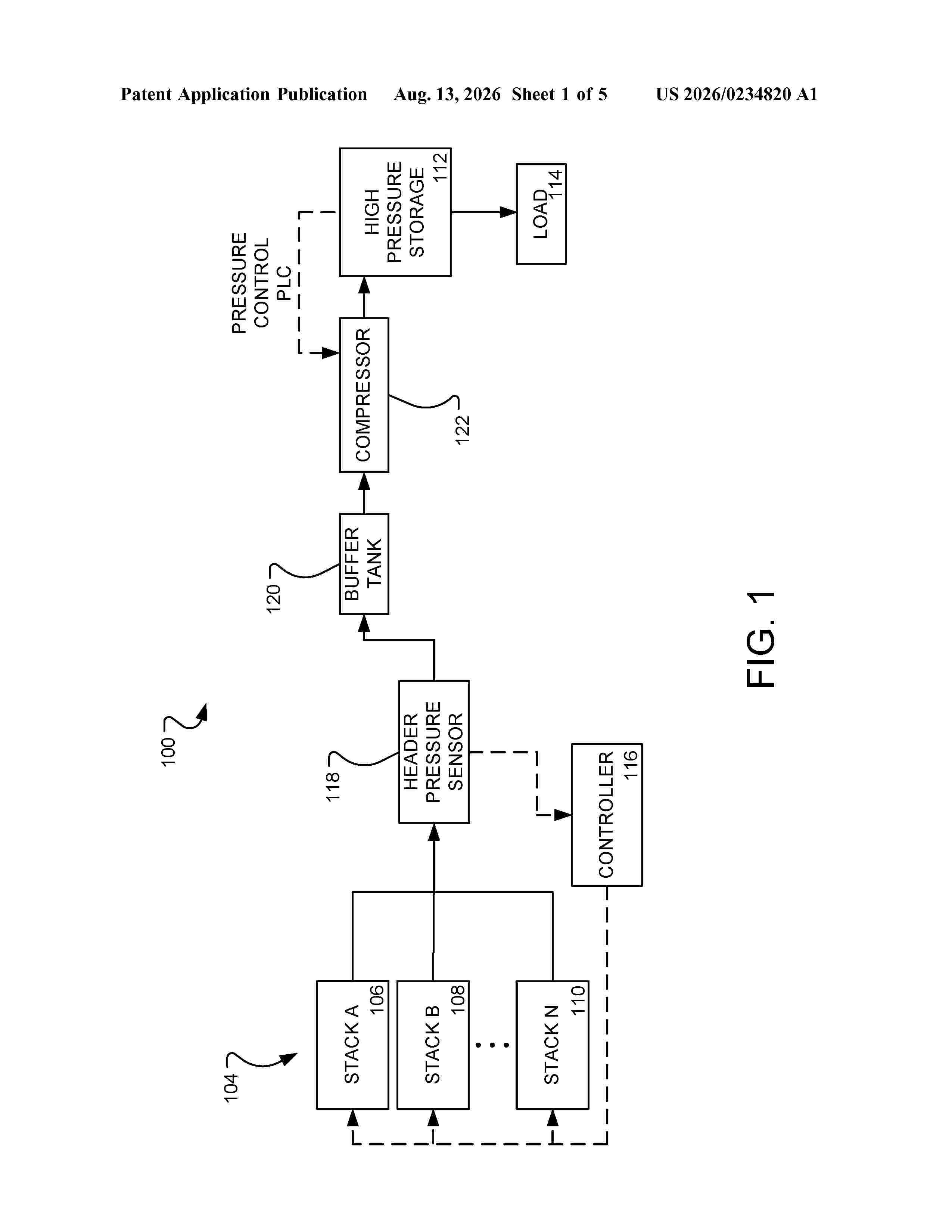
Resumen de: US20260234820A1
0000 The present disclosure relates to systems and methods for controlling hydrogen stack power and load. The systems include at least one hydrogen stack, a pressure sensor, and a controller, wherein the controller is operable to increase or decrease the power to the at least one hydrogen stack in response to a change in pressure. The methods include generating hydrogen using at least one hydrogen stack, measuring the pressure of the generated hydrogen, and increasing or decreasing the power supplied to the at least one hydrogen stack in response to an increase or decrease in the pressure.
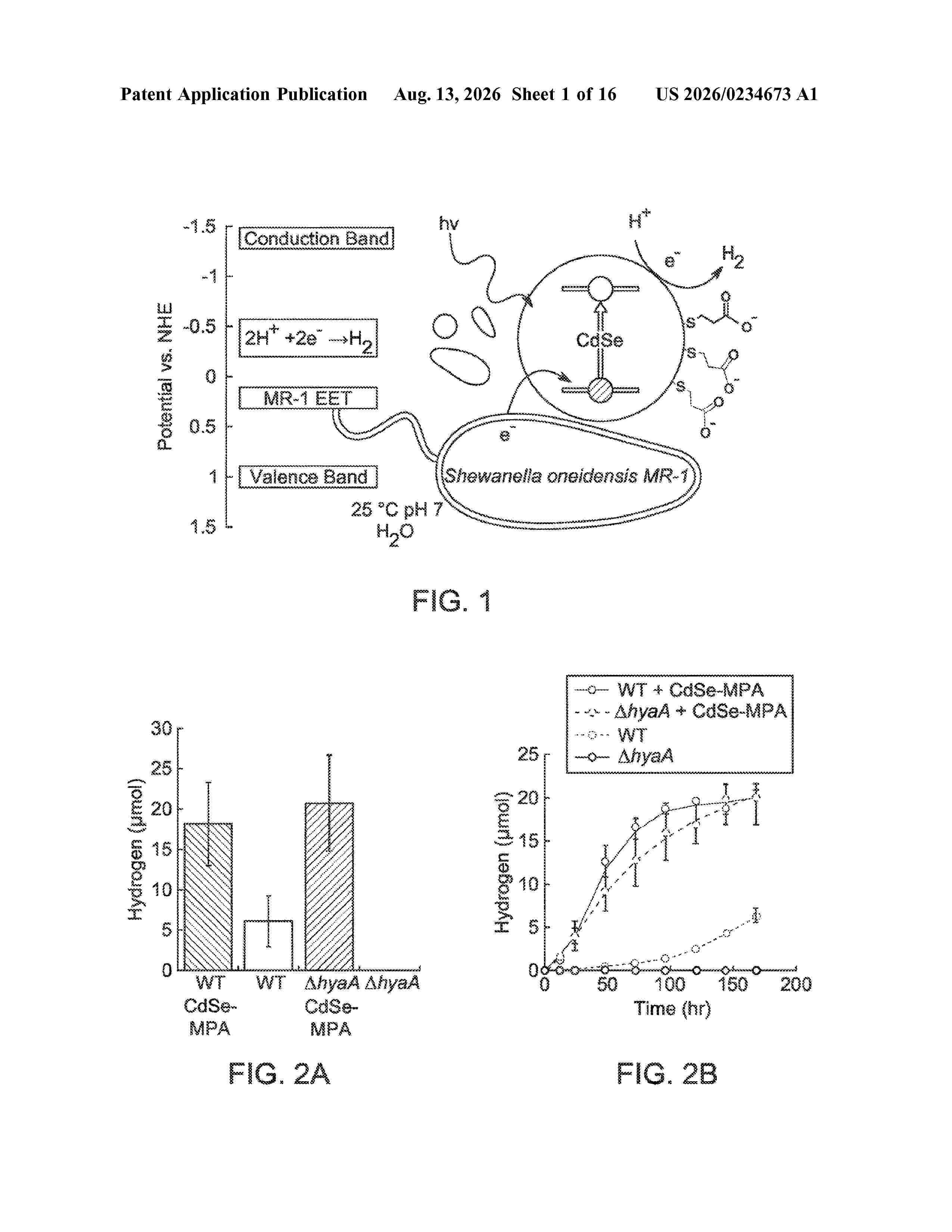
Resumen de: US20260234673A1
A composition that produces hydrogen includes a nanoparticle or plurality of nanoparticles; an external source of electrons such as an electrogenic bacterium or a plurality of electrogenic bacteria and a carbon source; and an aqueous medium. The nanoparticles and the aqueous medium are combined in a mixture and, upon exposure to electromagnetic radiation with a wavelength in the absorption profile of the nanoparticles, the nanoparticles generate an electron that can reduce a proton in the aqueous medium. The source of electrons is capable of reducing the nanoparticles. The nanoparticles may comprise cadmium chalcogenide or water-soluble cadmium chalcogenide quantum dots. The nanoparticles may also comprise core-shell nanoparticles, nanorods; dot-in rods, Zn-based II-VI core quantum dots, and nanoplatelets including core-crown and core-shell nanoplatelets. The electrogenic bacterium or bacteria may comprise Shewanella oneidensis, a Geobacter species or any bacterium capable of extracellular electron transfer.
Resumen de: US20260234822A1
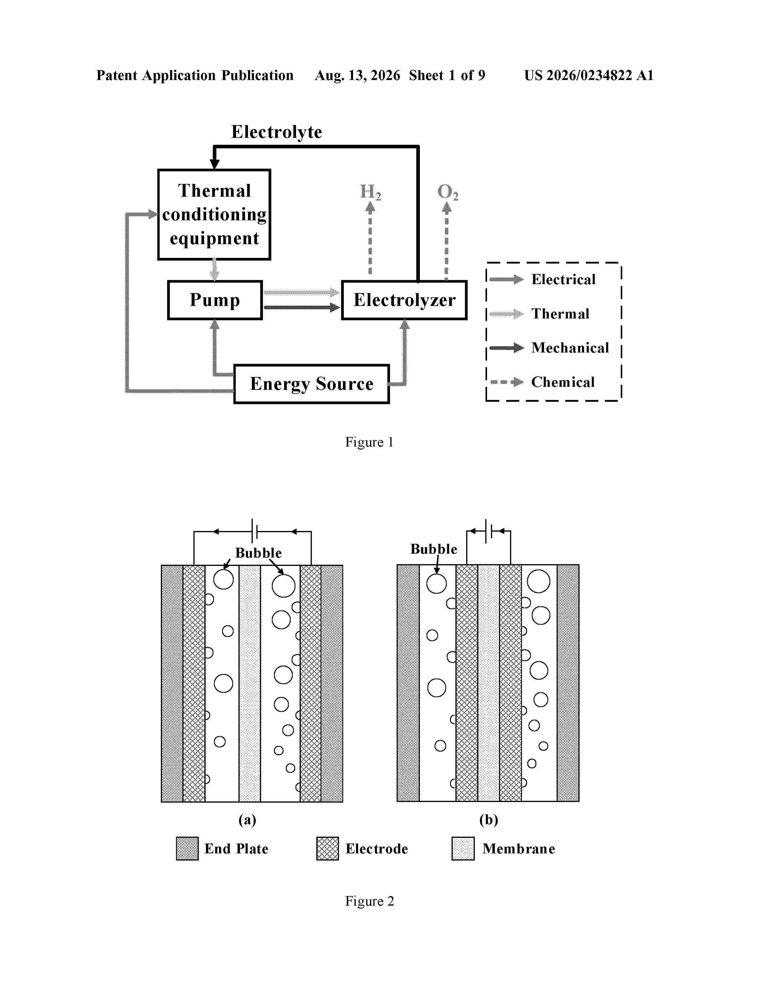
0000 A control unit for a Power-to-Hydrogen (PtH) plant is provided. The control unit includes at least one model and is configured to: calculate maximum efficiency point tracking of the PtH plant by solving an objective function having a predetermined hydrogen production rate of the PtH plant or a predetermined amount of energy input to the PtH plant using the at least one model, wherein the control unit receives measured parameters indicative of status of components of the PtH plant as an input to the at least one model; determine one or more set points for a coordinated operation of the components of the PtH plant based on a solution obtained by solving the objective function; and provide the one or more set points to one or more of the components of the PtH plant to operate the PtH at the maximum efficiency point.
Resumen de: US20260233204A1
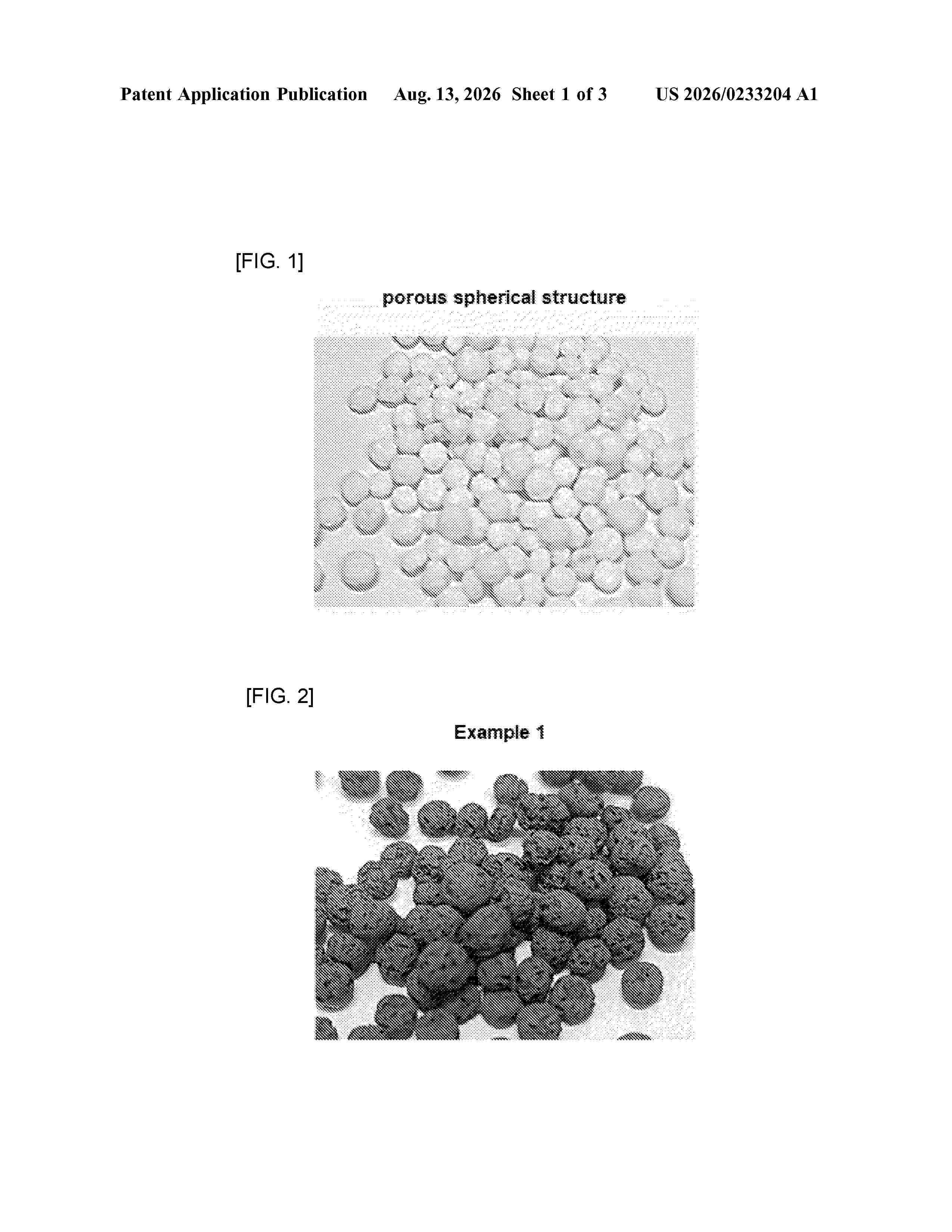
0000 A catalyst for decomposition of ammonia and a method for decomposition of ammonia using the catalyst. The catalyst includes a carrier and a catalytically active components supported on the carrier, the catalytically active components including i) ruthenium (Ru) as a first metal; ii) a second metal; and iii) a third metal, wherein each of the second metal and the third metal is independently one or more selected from the group consisting of lanthanum (La), cerium (Ce), aluminum (Al), and zirconium (Zr), the amount of the first metal ruthenium is 0.1 to 1 part by weight, based on 100 parts by weight of the total catalyst, the porosity is 30 to 60%, and the median value of pore diameter is 50 to 200 μm.
Resumen de: US20260234024A1
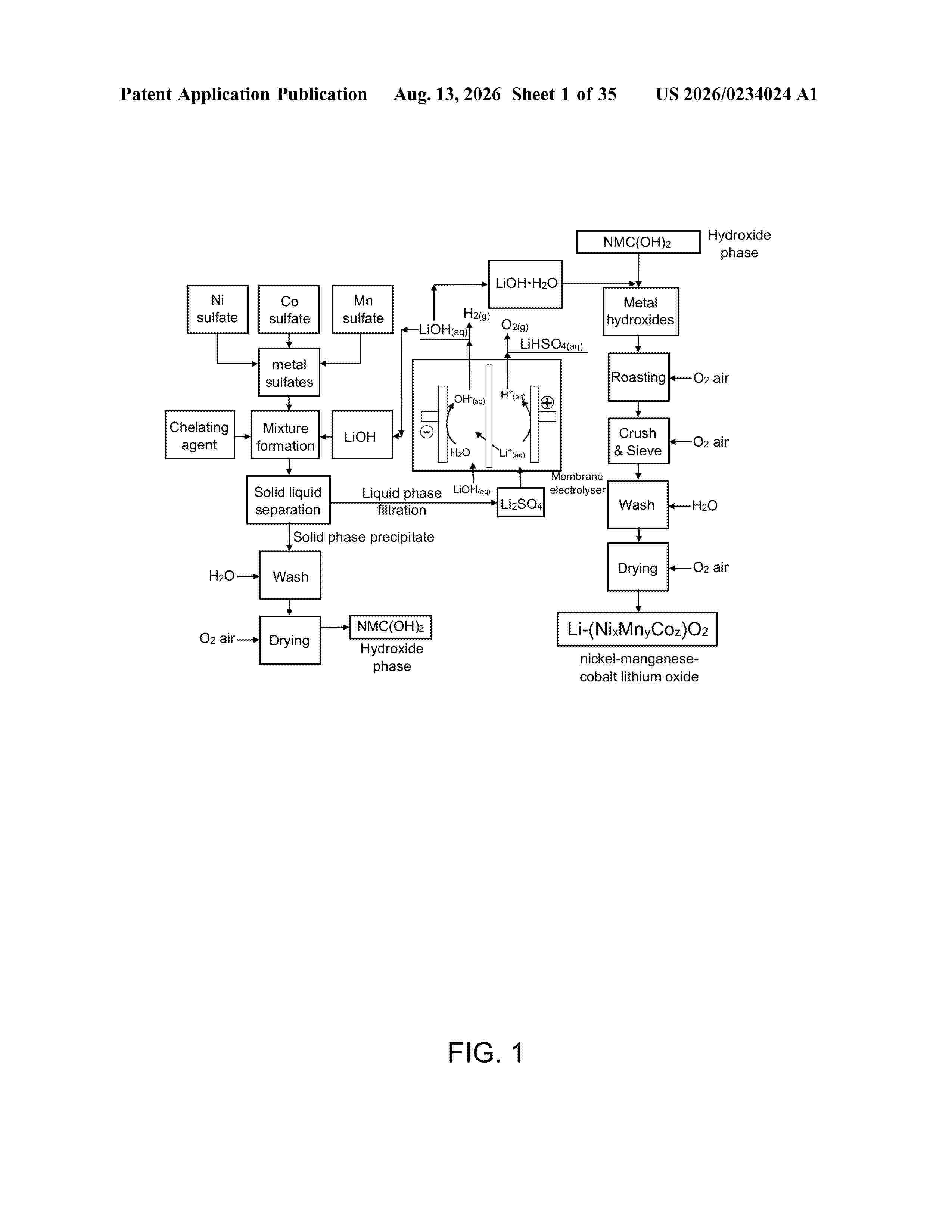
A process for process for preparing a metal hydroxide comprising at least one metal chosen from nickel, cobalt, manganese, lithium and aluminum. The process comprises: reacting a metal sulfate and/or a metal nitrate comprising at least one metal chosen from nickel, cobalt, manganese, lithium and aluminum with a base chosen from LiOH, NaOH, KOH, RbOH, CsOH, Mg(OH)2, Ca(OH)2, Sr(OH)2, or Ba(OH)2 and optionally a chelating agent in order to obtain a solid comprising the metal hydroxide and a liquid comprising at least one of Li2SO4 Na2SO4, K2SO4, Rb2SO4, Cs2SO4, MgSO4, CaSO4, SrSO4, BaSO4, LiNO3 NaNO3, KNO3, RbNO3, CsNO3, Mg(NO3)2, Ca(NO3)2, Sr(NO3)2 and Ba(NO3)2,separating the liquid and the solid from one another to obtain the metal hydroxide;submitting the liquid comprising at least one of Li2SO4 Na2SO4, K2SO4, Rb2SO4, Cs2SO4, MgSO4, CaSO4, SrSO4, BaSO4, LiNO3 NaNO3, KNO3, RbNO3, CsNO3, MgNO3, CaNO3, SrNO3 and BaNO3 to an electromembrane process for converting the least one of Li2SO4, Na2SO4, K2SO4, Rb2SO4, Cs2SO4, MgSO4, CaSO4, SrSO4, BaSO4, LiNO3 NaNO3, K2NO3, RbNO3, CsNO3, Mg(NO3)2, Ca(NO3)2, Sr(NO3)2 and Ba(NO3)2 into at least one of LiOH, NaOH, KOH, RbOH, CsOH, Mg(OH)2, Ca(OH)2, Sr(OH)2, and Ba(OH)2; andreusing the at least one of LiOH, NaOH, KOH, RbOH, CsOH, Mg(OH)2, Ca(OH)2, Sr(OH)2, and Ba(OH)2 obtained by the electromembrane process for reacting with the metal sulfate and/or the metal nitrate.
Resumen de: US20260235084A1
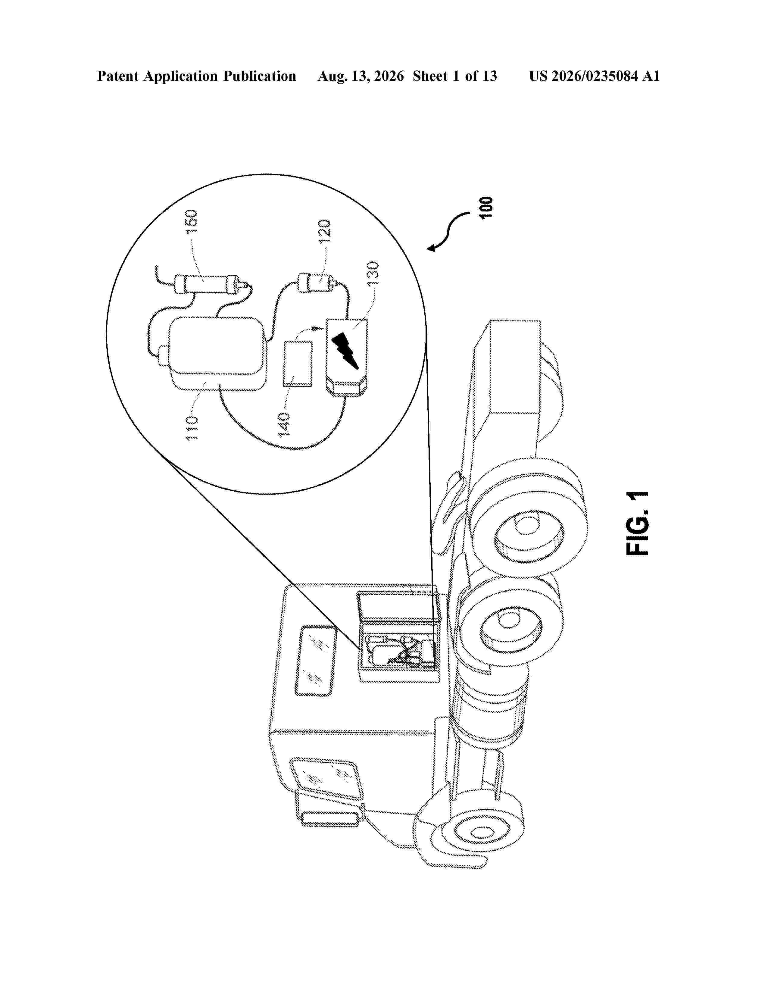
0000 According to aspects of the disclosed subject matter, methods and apparatuses are provided to reduce combustion time and/or combustion temperature in an internal combustion engine. In an exemplary embodiment, intake air and oxygen-rich gas are introduced upstream of a turbofan, wherein the amount of oxygen rich gas provided to the internal combustion engine is controlled in a manner that is proportional to the engine speed.
Resumen de: AU2025215475A1
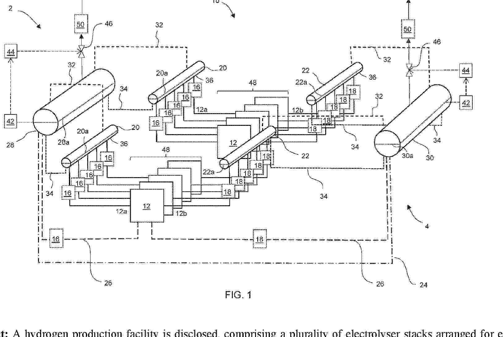
A hydrogen production facility is disclosed, comprising a plurality of electrolyser stacks arranged for electrolyzing water using an electrolyte and for generating at least a hydrogen-aqueous solution mixture; and a hydrogen separator arrangement for producing a flow of hydrogen from the hydrogen-aqueous solution mixture; wherein the hydrogen separator arrangement comprises a plurality of first stage hydrogen collector separators, the first stage hydrogen collector separators being fluidly coupled to a respective sub-set of the plurality of electrolyser stacks; and wherein the plurality of first stage hydrogen collector separators are fluidly coupled to a downstream hydrogen buffer vessel. A related method is further disclosed.
Resumen de: AU2025215031A1
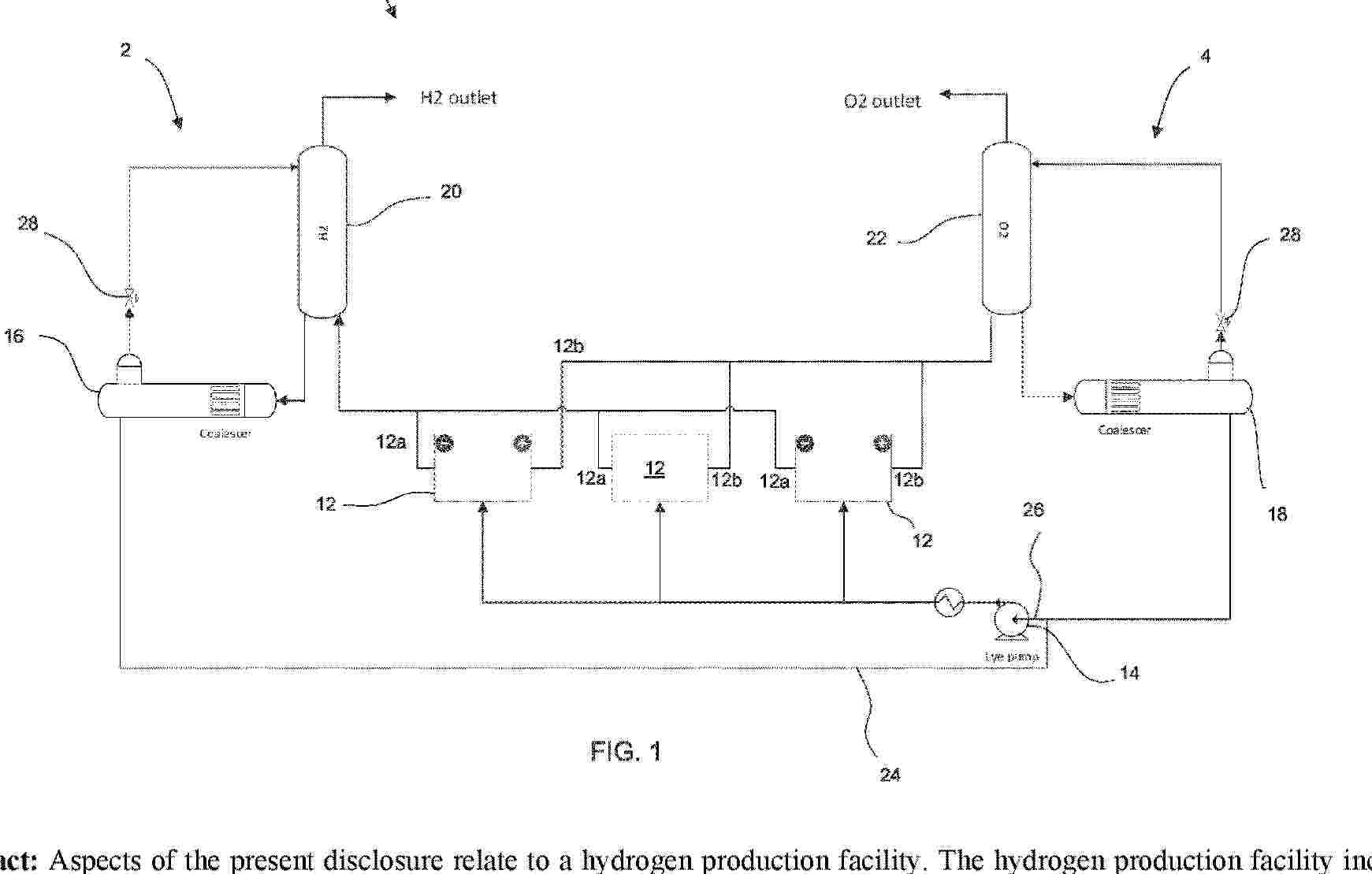
Aspects of the present disclosure relate to a hydrogen production facility. The hydrogen production facility includes one or more electrolyser stacks to electrolyze water using an electrolyte and generate a hydrogen-aqueous solution mixture and an oxygen-aqueous solution mixture, the one or more electrolyser stacks comprising a plurality of membranes. The facility also includes a hydrogen separator to produce a flow of hydrogen from the hydrogen-aqueous solution mixture and an oxygen separator to produce a flow of oxygen from the oxygen-aqueous solution mixture. The hydrogen separator comprises a hydrogen gas-liquid separation device and a hydrogen coalescing device. The oxygen separator comprises an oxygen gas-liquid separation device and an oxygen coalescing device.
Resumen de: AU2025216381A1
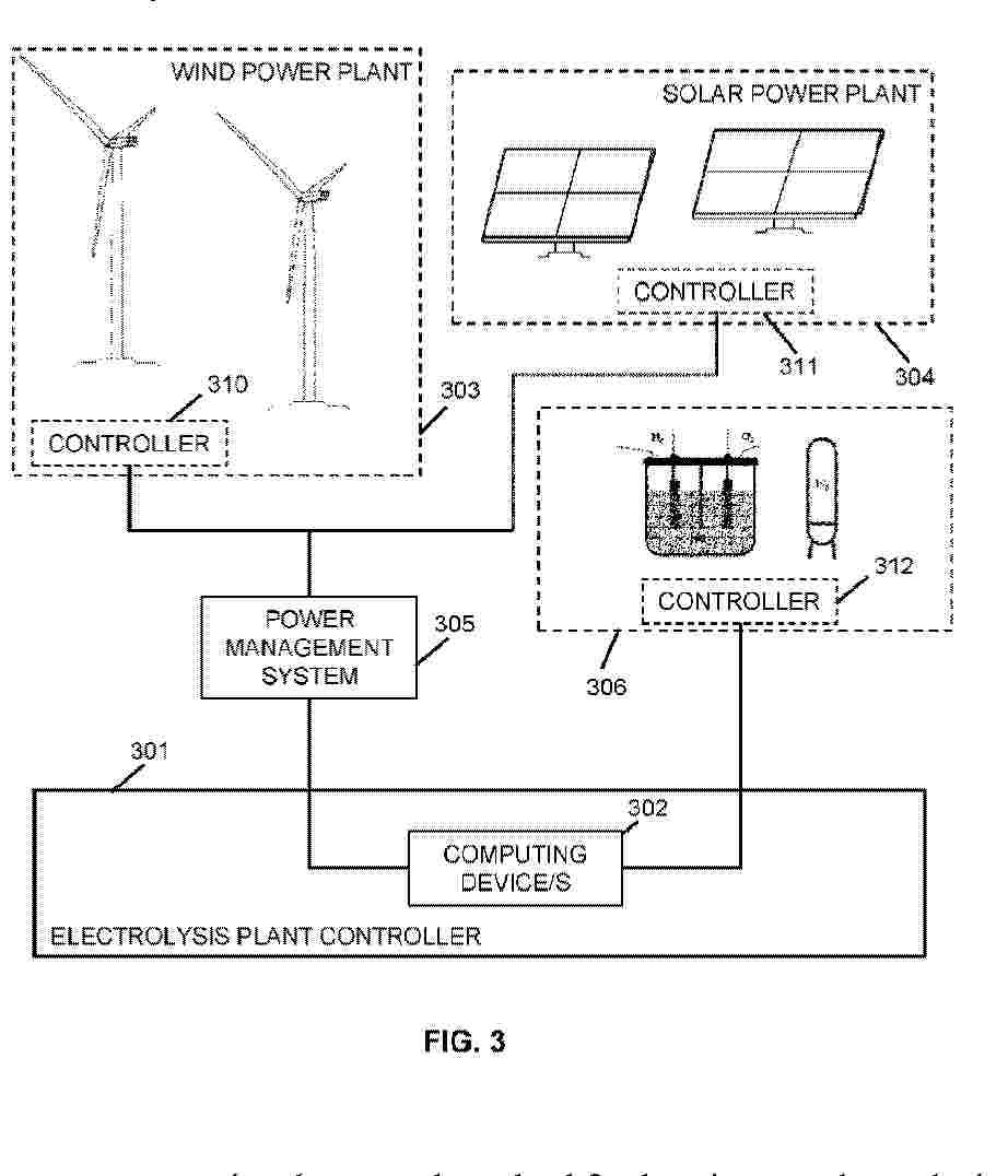
The disclosure refers to a computer-implemented method for heating up electrolytic units. The method comprises determining whether some electrolytic units of an electrolysis plant require heating up to have them at a temperature within a predetermined range in a future time span; controlling the electrolytic units to power them up based on first electric power available in a current time span; heating up the electrolytic units to have them at the temperature within the predetermined range in the at least one future time span; and repeating the steps such that the heating up is determined for one or more time spans that occur at the same time and/or later than the future time span, thereby repeatedly controlling the temperature of the electrolytic units to be at a temperature within the predetermined range in the future time spans.
Resumen de: AU2025216225A1
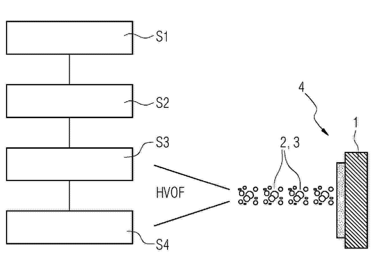
A method is disclosed for producing an electrode (4) having a noble metal catalyst for alkaline water electrolysis. The method comprises: (S1) providing the electrode substrate (1); (S2) providing a matrix material (2) and a catalyst material (3) as starting materials for the coating; (S3) mixing the matrix material (2) and the catalyst material (3); and, (S4) coating the substrate (1) with the mixture of matrix material (2) and catalyst material (3) by means of high-velocity oxygen fuel spraying (HVOF). A correspondingly produced electrode (4), an electrochemical cell (10) comprising said electrode, and an electrolyser (20) are also specified.
Resumen de: WO2026166566A1
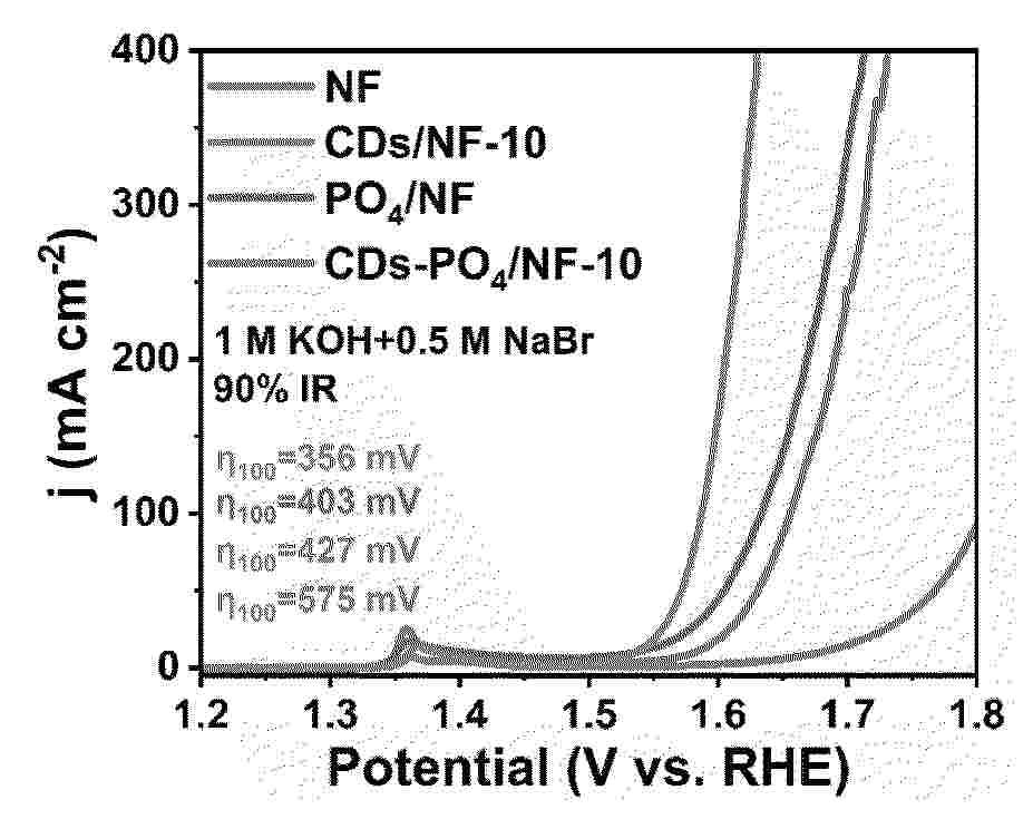
Preparation of phosphate-modified carbon quantum dot nickel-based catalyst and use thereof in alkaline seawater electrolysis, belonging to the technical fields of electrocatalysis and hydrogen production by seawater electrolysis. The method of preparing the present phosphate-modified carbon quantum dot nickel-based catalyst comprises the following steps: mixing citric acid and urea in water to obtain a carbon quantum dot precursor solution; and mixing the carbon quantum dot precursor solution, phytic acid, and a nickel substrate, then allowing for the reaction thereof so as to obtain the phosphate-modified carbon quantum dot nickel-based catalyst. In the present invention, a phosphate-modified carbon quantum dot nickel-based catalyst is designed by introducing a composite modification layer of carbon quantum dots and phosphate onto the surface of a nickel substrate. The synergistic effect of PO4 groups and CDs in the catalyst markedly improves OER activity, thereby allowing the catalyst to exhibit excellent oxygen evolution reaction activity and long-term stability in alkaline seawater containing Br- and Cl-.
Resumen de: WO2026168071A1
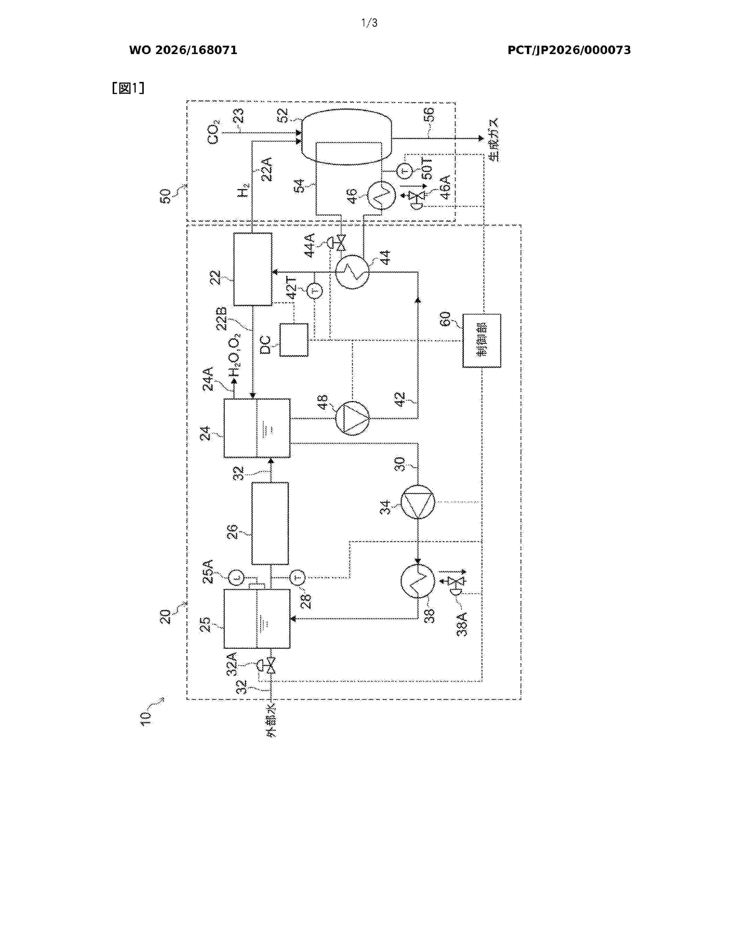
This water electrolysis system comprises: a water separation tank that is connected to a water electrolysis cell stack and that stores water discharged therefrom; an external water supply path that supplies normal-temperature external water; a water circulation path that is provided with a water circulation pump, that is connected to the water separation tank and the external water supply path, and that circulates the water in the water separation tank via the external water supply path; an ion exchange resin provided on the downstream side of a part where the external water supply path merges with the water circulation path; a cooling unit that cools the water in the water circulation path so that the temperature of the water that merges with the external water and flows into the ion exchange resin, and has a temperature higher than normal temperature, falls below a prescribed ion exchange resin upper limit temperature; and a water supply path that serves as a path separate from the water circulation path, said water supply path being provided with a water supply pump, heating the water from the water separation tank through use of a heating unit, and supplying the heated water to the water electrolysis cell stack.
Resumen de: AU2025215616A1
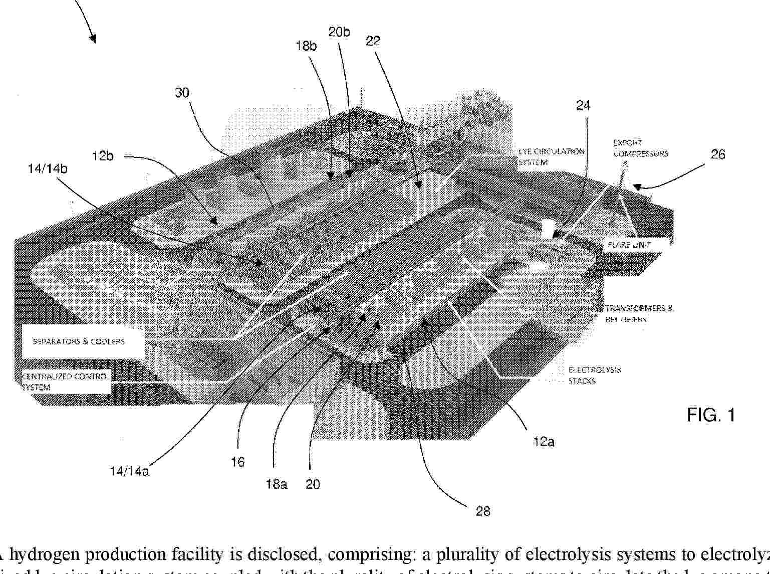
A hydrogen production facility is disclosed, comprising: a plurality of electrolysis systems to electrolyze water using lye; and a mutualized lye circulation system coupled with the plurality of electrolysis systems to circulate the lye among the plurality of electrolysis systems to facilitate electrolyzing the water, the lye circulation system comprising one or more pumps, wherein a number of the one or more pumps is less than a number of electrolysis systems of the plurality of electrolysis systems. A hydrogen production facility comprising first and second modular structures is also disclosed.
Resumen de: US20260235020A1
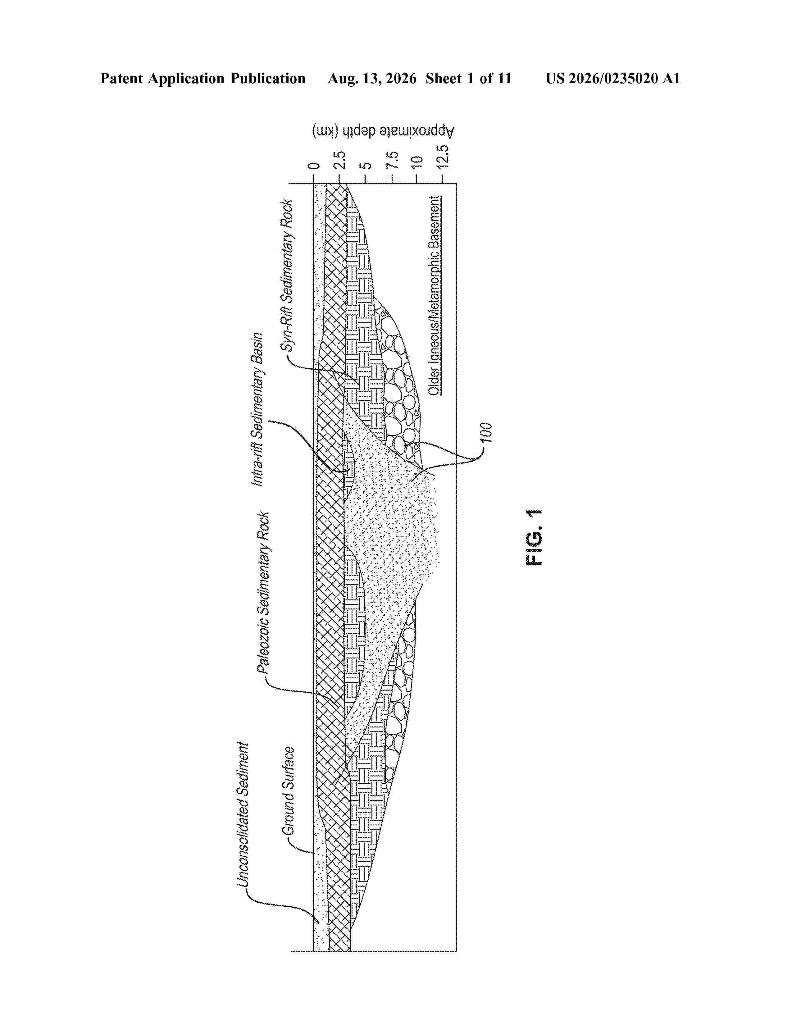
0000 A method of producing hydrogen and sequestering carbon or sulfur includes generating a fluid including at least one of water, steam, hydrogen sulfide, carbon dioxide and heat as a byproduct of a surface facility and injecting the fluid into a subsurface formation. The subsurface formation can include a porous rock, in various forms of porosity such as intragranular, intergranular, fracture porosity. The method can further include heating the fluid to stimulate an exothermic reaction of the fluid with components of the subsurface rock formation and produce a hydrogen reaction product and one or more of sulfur minerals from the hydrogen sulfide or carbon minerals from the carbon dioxide. The fluid can be heated to between about 25° C. and about 500° C. The method can also include extracting the hydrogen produced from the reaction of the fluid with the subsurface rock formation and mineralizing sulfur or carbon in the porous rock.
Resumen de: WO2026167518A1
Apparatus (100) for the production of hydrogen by means of electrolysis of water, comprising a central body (120) consisting of a refractory chamber and comprising: a first zone (101) comprising a burner; a second zone (102) directly connected with the first zone (101) and arranged downstream of the latter, provided with devices (111) for controlling the temperature of the combusted gas exiting from said first zone and for regulating and delivering a coolant; and a third zone (103), directly connected with the second zone (102), comprising a high-temperature solid oxide electrolytic cell (SOEC), said apparatus (100) further comprising: upstream of the central body (120) at least one supply line (104), (105) and (106) for respectively supplying at least one fuel; oxygen and a diluent, and directly connected with the third zone (103) of the central body: an outlet line (107), and (108) for hydrogen and any carbonaceous combusted gases; and oxygen.
Resumen de: US20260235369A1
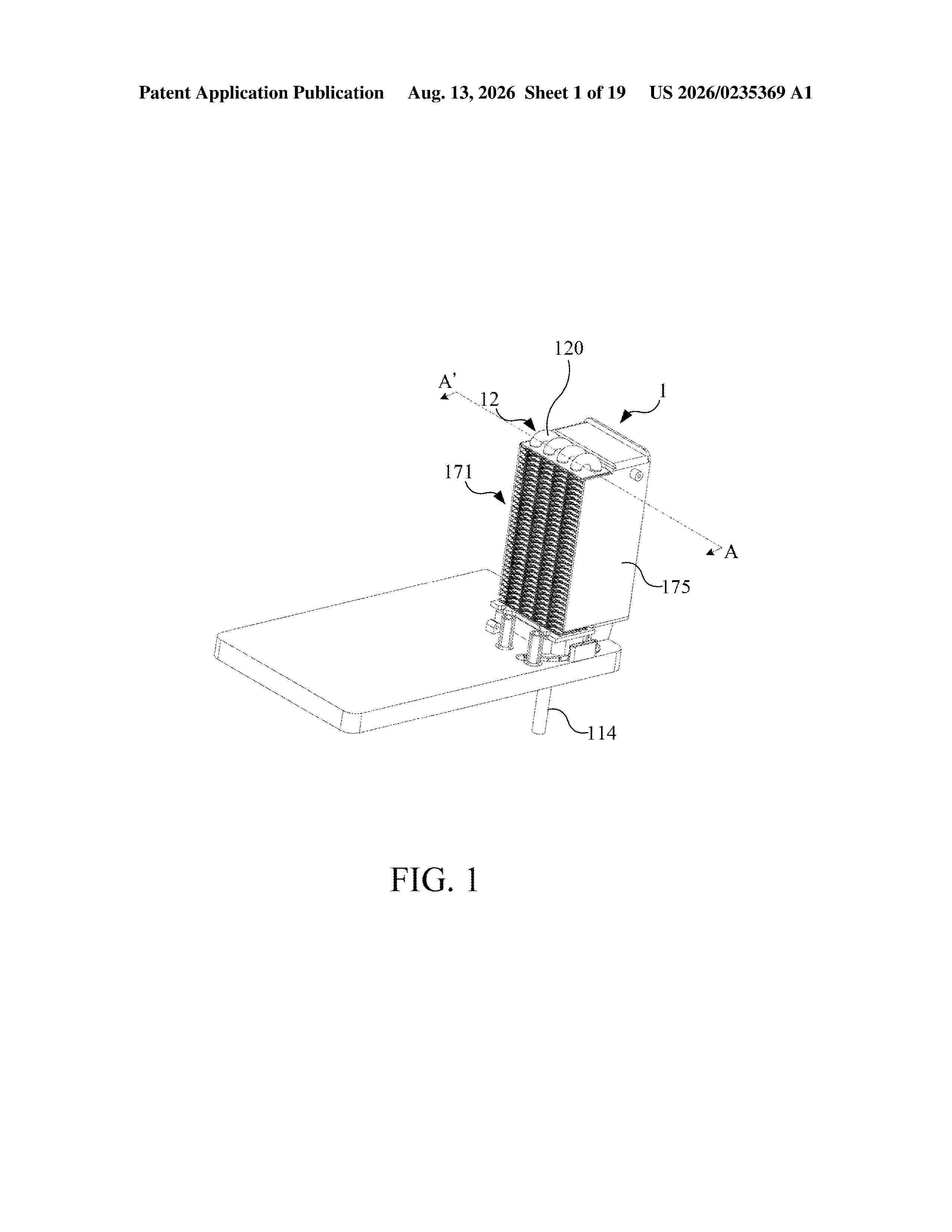
A radiator includes a base, a tubular structure, a plurality of fins and a spiral structure. The base has a water input port and a water output port. The tubular structure is coupled to the base and is further connected with the water input port and the water output port. A spiral structure is arranged inside the tubular structure, or the inner surface of the tubular structure has a delay structure formed by a plurality of bumps for improving heat dissipation efficiency of water. The tubular structure runs through the plurality of fins. In addition, the radiator of the present invention is applied to a hydrogen generator. The base of the radiator is directly and integrally formed with the upper cover of the water tank of the hydrogen generator, and the assembly can be completed only by coupling the base to the tube, thereby reducing the assembly process.
Resumen de: US20260237702A1
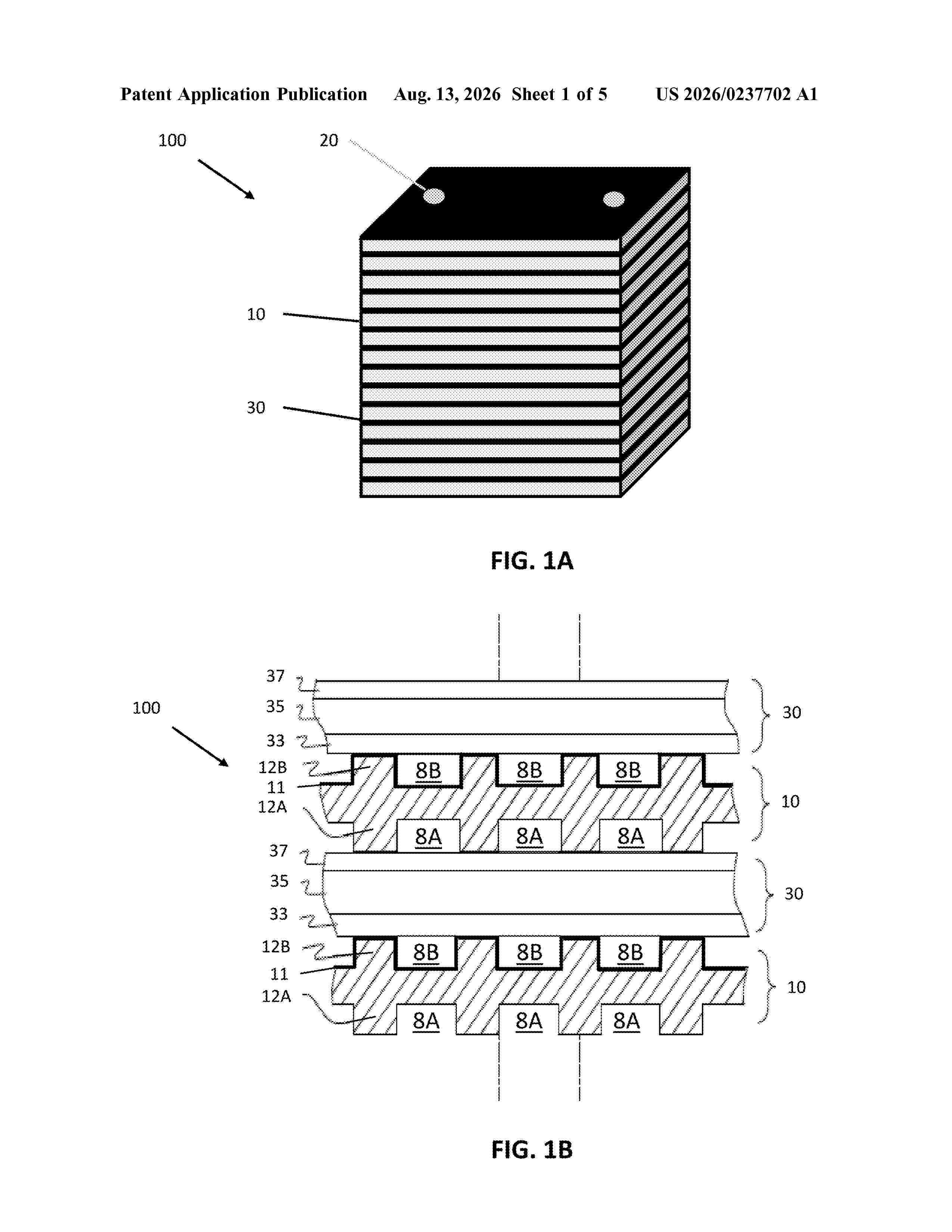
0000 A power generation system includes an electrolyzer system configured to generate hydrogen using power received from a power grid, a hydrogen storage device configured to store generated hydrogen, a fuel cell system configured to generate power for a load using at least one of hydrogen received directly from the electrolyzer system, hydrogen received from the hydrogen storage device, or a hydrocarbon fuel received from a hydrocarbon fuel supply, and a controller configured to determine a CO<2 >per kWh power grid emission rate (GER) of a power grid electrically connected to the power system, and control operation of the fuel cell system and the electrolyzer system based on a comparison between the GER, a CO<2 >per kWh hydrocarbon fuel (e.g., natural gas) emission rate of the fuel cell system (NER), and a CO<2 >per kWh target emission rate (TER) that is less than the NER.
Resumen de: WO2026167416A1
The underlying invention is related to a device and a process for the direct production of an energy storing fluid from a reactant and an electrolyte in an electrochemical twin reactor, comprising a first reactor part which has at least one anode and an electrolyte for dissolving the reactant and a second reactor part which is comprising at least one further anode and a further electrolyte as a hydrogen source.
Resumen de: WO2026167020A1
The invention relates to a method for preparing methanol, comprising the method steps of: a) acidifying seawater and heating same to at least 45°C, b) removing oxygen from the gas mixture obtained in step a) while preserving carbon dioxide, c) distilling some of the low-carbon-dioxide seawater remaining in step a) to obtain distilled water and brine, d) electrolysing the distilled water, e) obtaining acid and an alkaline residue from the brine, f) using the acid obtained in step e) to acidify the seawater in step a), g) recovering at least some of the waste heat produced in steps b) to e) and using same for heating the seawater in step a), h) synthesising methanol from the hydrogen from step d) and the carbon dioxide from step b) and separating the methanol from the product mixture.
Resumen de: US20260234818A1
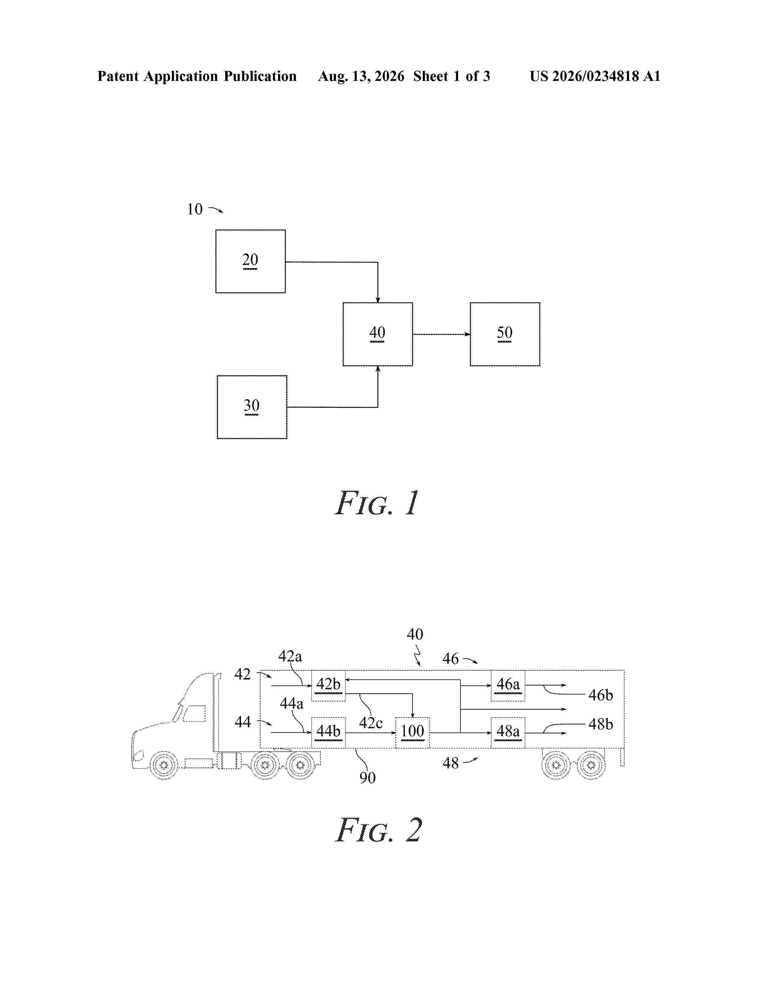
0000 Systems, methods, and devices for enhancing catalyst layer performance in electrolytic cells are described. The enhanced catalyst layers include a catalyst mixture having catalyst particles and corrosion-resistant, conductive nanoparticles to optimize interfacial contact and reduce in-plane discontinuities even at low areal loadings of catalyst particles. For example, a catalyst layer includes a matrix with a homogenous mixture of catalyst particles and corrosion-resistant, conductive nanoparticles. The catalyst particles are configured to promote water electrolysis. The catalyst particles include iridium and have a high surface area. The corrosion-resistant, conductive nanoparticles are configured to resist oxidation, to reduce packing discontinuities of the catalyst particles, and to provide an electrically conductive bridge between the catalyst particles. The matrix is configured to support the catalyst particles and the corrosion-resistant, conductive nanoparticles.
Resumen de: DE102025105318A1
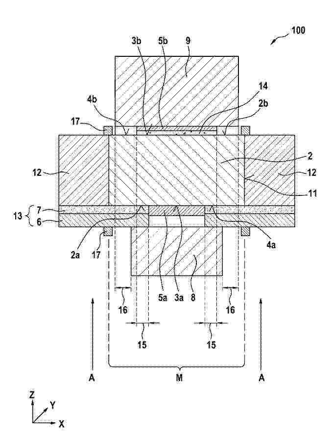
Die Erfindung betrifft eine katalysatorbeschichtete Membran (100) mit einer Kathode (5a), einer Anode (5b) und einer zwischen der Kathode (5a) und der Anode (5b) liegenden lonomermembran (2), zur Anwendung in der Wasserelektrolyse, wobei die lonomermembran (2) eine erste Oberfläche (2a) und eine zweite Oberfläche (2b) aufweist und die erste Oberfläche (2a) eine erste aktive Fläche (3a) und die zweite Oberfläche (2b) eine zweite aktive Fläche (3b) aufweist, wobei die erste aktive Fläche (3a) und die zweite aktive Fläche (3b) jeweils mit einer Katalysatorschicht beschichtet sind; wobei die erste aktive Fläche (3a) von einer ersten passiven Fläche (4a) und die zweite aktive Fläche (3b) von einer zweiten passiven Fläche (4b) umgeben ist; die katalysatorbeschichtete Membran (100) ferner umfassend eine Folie (12), die einen Außenumfang (11) der lonomermembran (2) umgibt ohne mit der lonomermembran (2) zu überlappen, wobeia) wenn eine Schichtdicke der Folie (12) größer ist als eine Schichtdicke der lonomermembran (2), ein Unterschied der Schichtdicke der Folie (12) und der Schichtdicke der lonomermembran (2) in Schichtdickenrichtung (Z), senkrecht zur Schichtausdehnungsrichtung (XY), weniger als 50 µm, bevorzugt weniger als 30 µm, weiter bevorzugt weniger als 20 µm, noch weiter bevorzugt weniger als 10 µm und am meisten bevorzugt weniger als 5 µm beträgt undb) wenn die Schichtdicke der lonomermembran (2) größer ist als die Schichtdicke der Folie (12), ein Unt
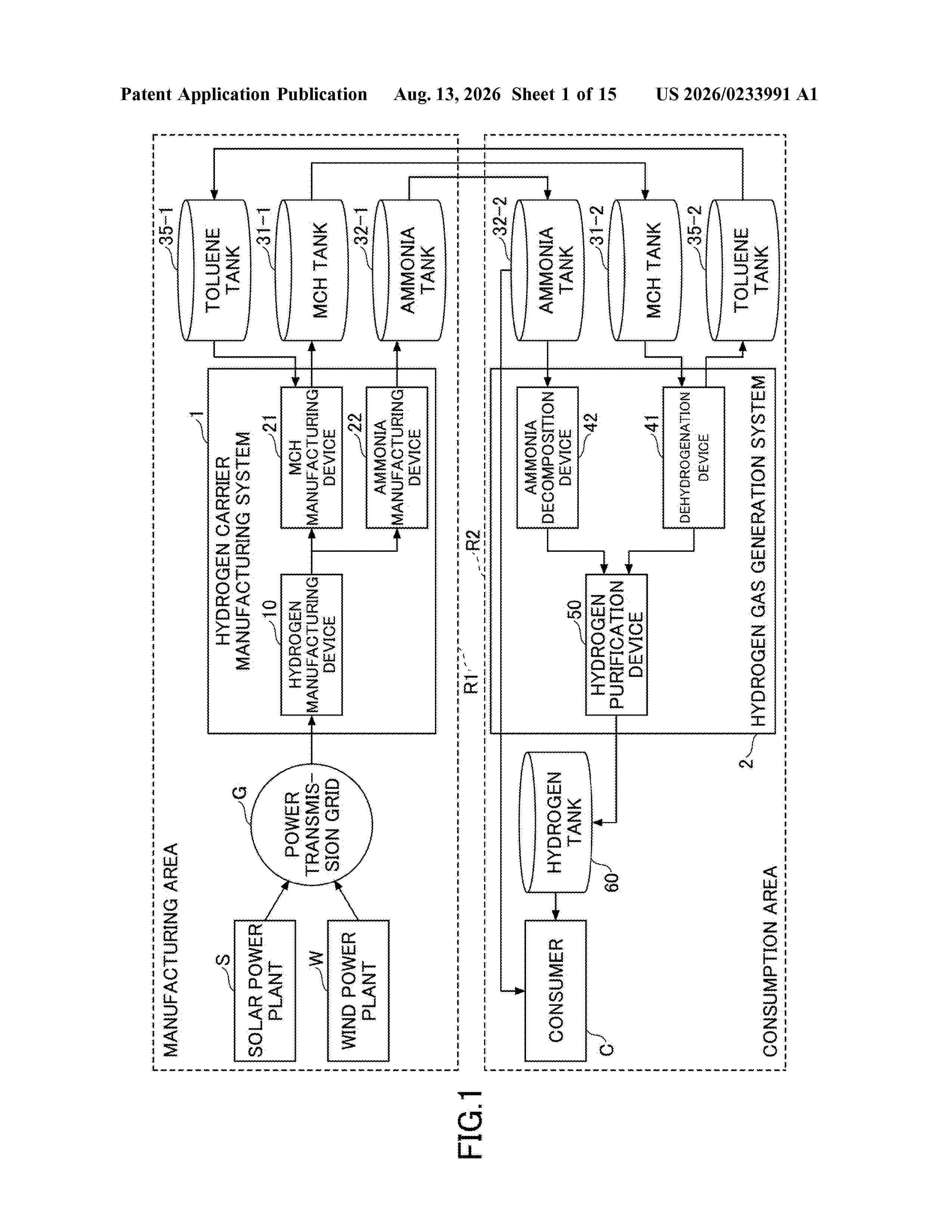
Resumen de: US20260233991A1
0000 A hydrogen carrier manufacturing system includes a hydrogen manufacturing device configured to manufacture hydrogen by using power; a hydrogen tank configured to store the hydrogen manufactured by the hydrogen manufacturing device; and a plurality of hydrogen carrier manufacturing devices configured to convert the hydrogen stored in the hydrogen tank into different types of hydrogen carriers.
Nº publicación: EP4790295A1 12/08/2026
Solicitante:
HITACHI LTD [JP]
Hitachi, Ltd.
Resumen de: EP4790295A1
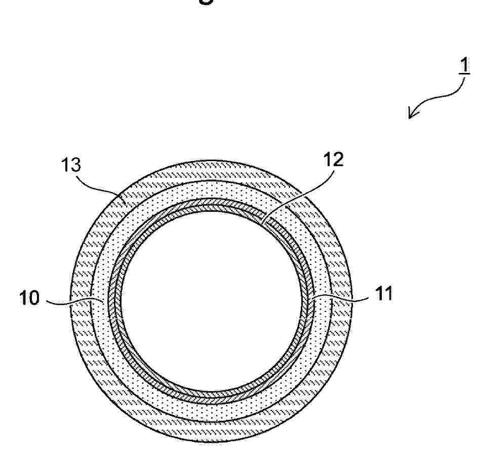
0001 Provided is a multilayer resin pipe suitable for use in a water electrolysis system operating at high voltage, a water electrolysis system including the multilayer resin pipe, and a method of transporting hydrogen using the multilayer resin pipe. The multilayer resin pipe includes an electrically insulating main pipe, an electrically insulating pressure-resistant layer covering an outer surface of the main pipe, an electrically insulating gas barrier layer covering an inner surface of the main pipe, and an electrically insulating elution-suppressing layer covering an inner surface of the gas barrier layer.
 BOPI
BOPI
 Sede Electrónica