Si deseas distinguir tus productos, servicios o ambos de los de otra empresa, es posible que necesites una marca o nombre comercial. Descubre qué son, en qué consiste su procedimiento de registro y qué implica.

Información sobre los plazos de presentación de solicitudes de transformación de marcas de la Unión Europea en marca nacional española. Más información


Si tienes un nuevo dispositivo, producto o procedimiento que resuelva un problema técnico o tenga una ventaja práctica, existen distintas formas de protegerlo en España y en otros países. Descubre cómo hacerlo.

¿Tu innovación reside en la estética, la ornamentación o la apariencia de tu producto? Protégela mediante un diseño industrial. Descubre qué derechos confiere el registro y cómo realizar la tramitación.

Las indicaciones geográficas protegen el nombre de un producto originario de una zona geográfica, a la cual le debe una determinada calidad, reputación u otra característica. Descubre qué son, en qué consiste su procedimiento de registro y qué beneficios conceden.

Las patentes publicadas en todo el mundo son una valiosa fuente de información científica, técnica y comercial.

Si eres emprendedor/a o una empresa y quieres potenciar y mejorar la rentabilidad de tu negocio protegiendo de forma adecuada los activos intangibles de tu organización, en este espacio encontrarás lo necesario.


 782
resultados
782
resultados
 Última actualización
28/04/2026 [07:05:00]
Última actualización
28/04/2026 [07:05:00]


 Resultados 125 a 150 de 782

Resumen de: CN121802433A
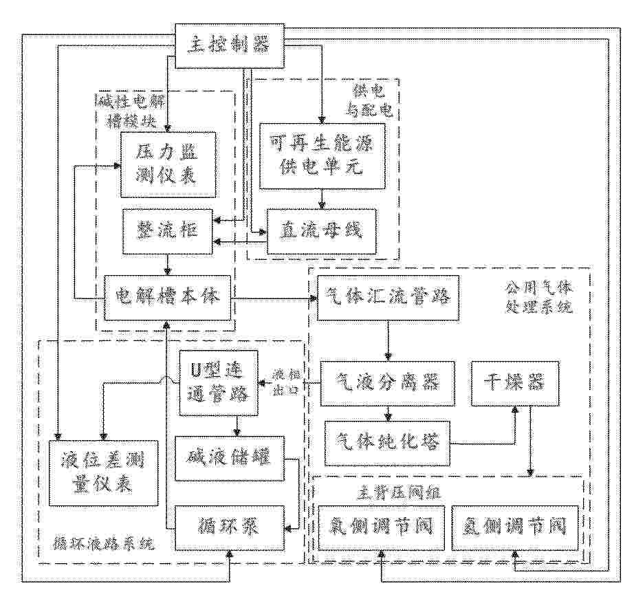
0001 本发明涉及离网可再生能源制氢技术领域,公开了离网型碱性制氢系统及其功率自适应分配与安全控制方法,包含可再生能源供电单元、并联电解槽模块、气液处理系统及主控制器;主控制器依据预测功率判定运行状态:在法拉第制氢模态,通过调节运行压力压缩气泡体积以调制电解槽阻抗特性,配合电流控制提升能效;在非法拉第极化热备模态,控制整流柜电压钳位至非析气极化区间,并利用流体静力学原理在U型连通管路构建液位封堵。系统还配置有基于气动容量的瞬态缓冲策略,在功率骤降时利用气体死区体积延缓压力衰减。本发明有效解决了宽功率波动下的制氢效率优化、低功率安全热备及机械防护问题。

Resumen de: CN121802473A
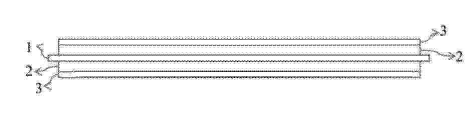
0001 本发明提供了一种用于电解水制氢的复合隔膜及其制备方法、制备装置与电解制氢装置,所述复合隔膜包括支撑体,及所述支撑体的至少一层表面上依次层叠设置的小孔径涂层与大孔径涂层;所述小孔径涂层的平均孔径为10nm~0.2μm,所述大孔径涂层的平均孔径为150nm~1μm;本发明提供的用于电解水制氢的复合隔膜,具有优异的导离子能力,面电阻低,能够满足电解水制氢对低运行成本的要求;另外,所述复合隔膜还具有优异的隔绝气体能力,且具有较高的泡点压力,能够保证电解槽的运行安全性;因此,所述复合隔膜满足电解槽对运行低成本和高运行安全性的双重要求。
Resumen de: CN121800142A
本发明提供了一种脱氧塔,其包括:塔体、催化填充结构、加热柱及转向筒;塔体内开设工作空间;塔体底部开设有排污口及位于排污口上方的出气口;催化填充结构设置于工作空间内;加热柱内开设有供混合气体由上方进气口至下方输出口流动的加热腔,加热腔用于将流经其内的混合气体加热至预设温度区间;转向筒间隔套设于加热柱上,以与加热柱之间形成转向通道;转向通道的入口连通输出口,转向通道的出口连通工作空间且位于催化填充结构上方。当混合气体经过加热器加热后输入至工作空间时,于工作空间内缓慢向下流经催化填充结构,从而延长混合气体在催化填充结构处的停留时间,提高氧气、氢气的氧化反应效果,以提高输出的氢气的纯度。
Resumen de: CN121802447A
本发明公开了一种吸附铁的多孔双功能电极制备方法、电极及装置,其中方法,包括如下步骤:准备多孔电极;以多孔电极为阴极和阳极,在添加有铁源的强碱溶液中,周期性恒电流吸附铁反应4~20 h,其中任一周期包括一次还原性吸附和一次氧化性吸附。本发明通过对多孔电极进行铁吸附修饰,能够使得吸附的铁物种能够进入并富集于孔道内部,有效提升电极的OER性能,同时,确保电极的主体结构或表面具有抗铁吸附特性,维持其优异的HER催化活性。
Resumen de: CN121802462A
0001 一种基于气相界面工程的非贵金属酸性析氧催化涂层、其制备方法及应用。主要解决目前的非贵金属酸性析氧催化涂层耐久性不足的问题。本发明提供一种基于气相界面工程的非贵金属酸性析氧催化涂层、其制备方法及应用,该方法在基底上形成晶态金属氧化物涂层;然后采用原子层沉积或化学气相渗透工艺,将改性元素前驱体以气相形式引入,使其在所述涂层的内部晶界及孔隙表面发生吸附与反应,原位构建包裹晶粒的非晶态金属氧化物界面,该界面可显著强化晶界,提升涂层在强酸性环境(如质子交换膜电解水)中的电化学稳定性,同时保持了良好的析氧反应活性。
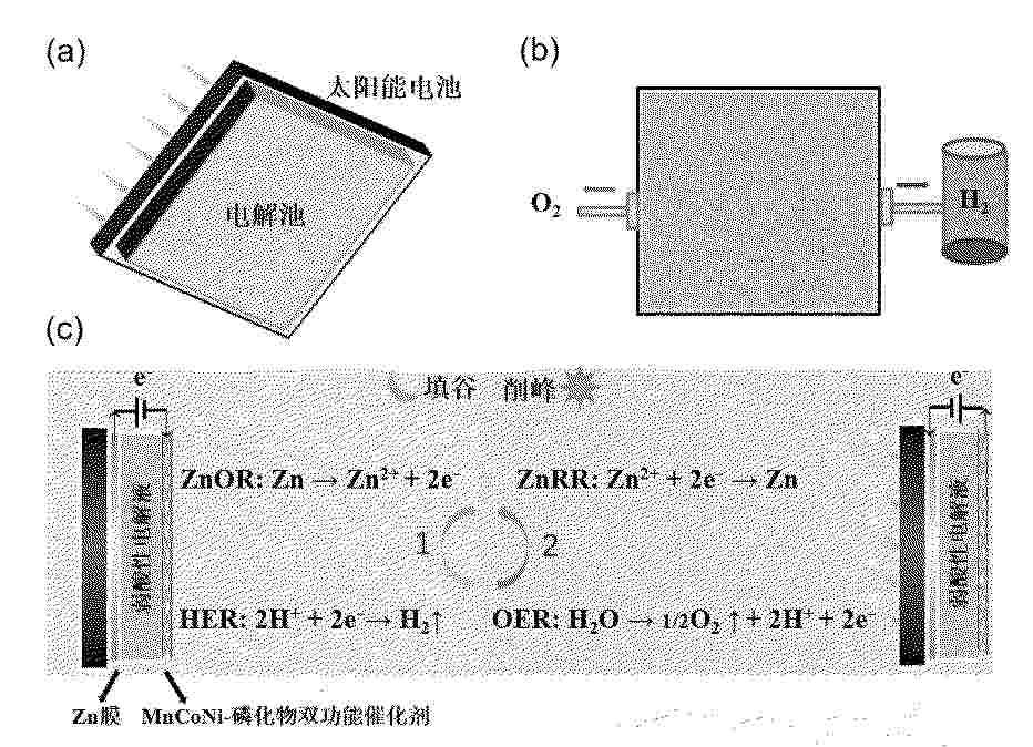
Resumen de: CN121802441A
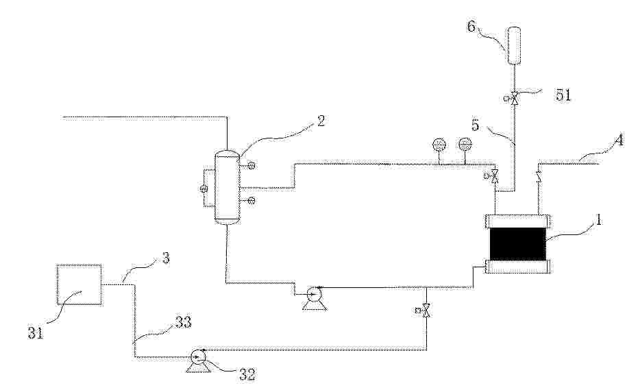
本发明提供了一种太阳能电池耦合电解池分布式产氢气和排氧气的方法,属于氢气制备方法技术领域。本发明将MnCoNi‑磷化物复合双功能催化剂作为工作电极,将锌膜作为辅助电极,与弱酸性缓冲电解液组装得到电解池,并采用2N个太阳能电池与3N个电解池进行耦合,在时间上通过交替进行锌氧化反应/析氢反应和锌还原反应/析氧反应,分别制备氢气和氧气,在电解反应切换的同时,通过切换气路导向即可分别收集氢气和排出氧气,解决了氢气和氧气气体交叉问题,实现了高效制氢;此外,本发明的分布式制氢和排氧的太阳能电池‑电解池耦合系统具有简单、成本低廉的优势,具有广阔的应用前景。
Resumen de: CN121797310A
本发明公开了一种用于氨分解的钌催化剂及其制备方法,其是以氧化铝为载体,氧化铈为助剂,钌为活性组分的催化剂。催化剂的制备中先将铈的水溶液浸渍到氧化铝并在含氨气氛中进行热处理,然后浸渍钌的醇溶液引入钌活性组分,最后在含碳气氛中进行热处理、还原得到最终的催化剂。与现有方法制备的氧化铝负载钌催化剂相比,本发明所得催化剂具有较高的氨分解活性,有较好的应用前景。
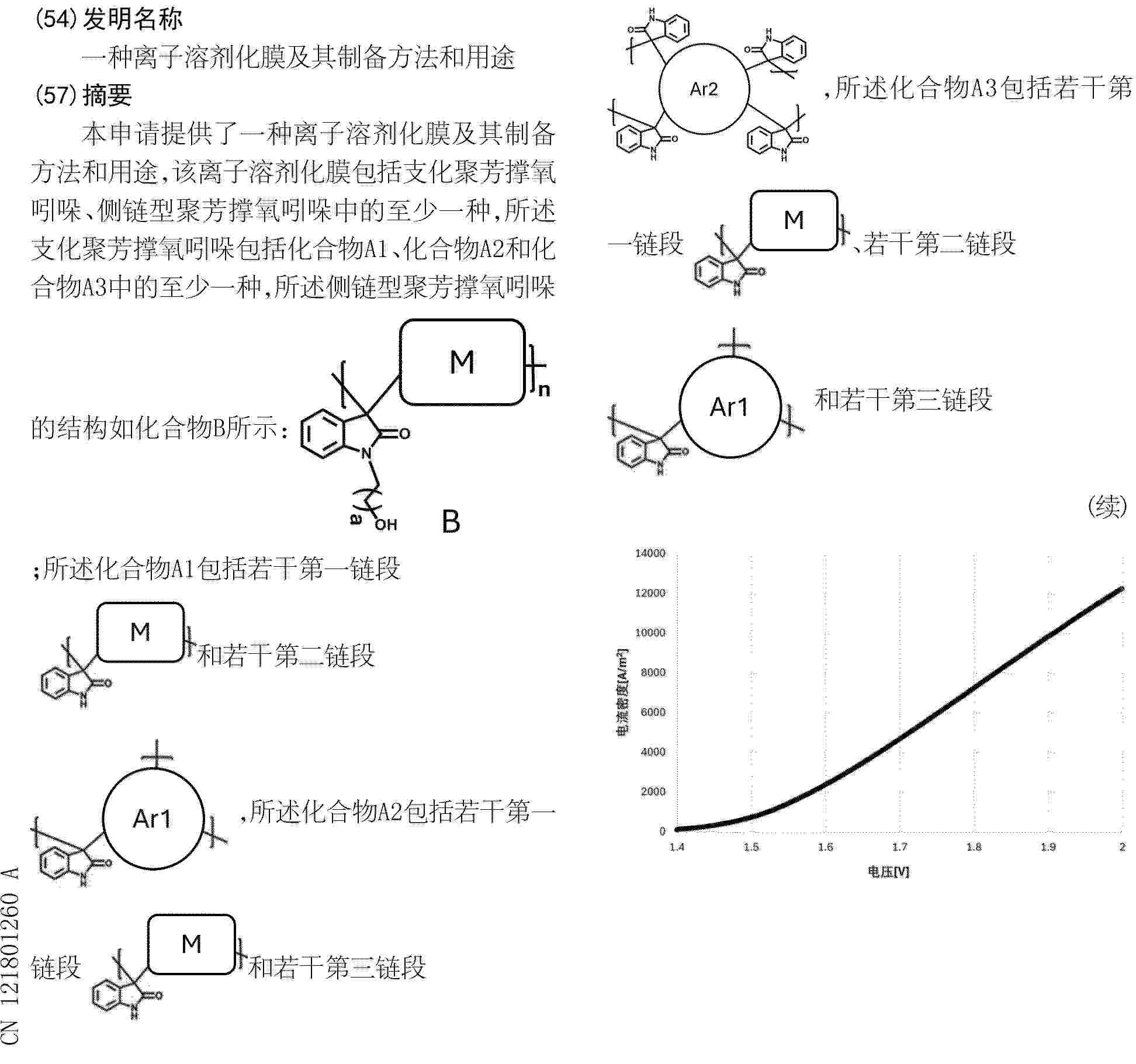
Resumen de: CN121801260A
0001 本申请提供了一种离子溶剂化膜及其制备方法和用途,该离子溶剂化膜包括支化聚芳撑氧吲哚、侧链型聚芳撑氧吲哚中的至少一种,所述支化聚芳撑氧吲哚包括化合物A1、化合物A2和化合物A3中的至少一种,所述侧链型聚芳撑氧吲哚的结构如化合物B所示:
;所述化合物A1包括若干第一链段
和若干第二链段
,所述化合物A2包括若干第一链段
和若干第三链段
,所述化合物A3包括若干第一链段
、若干第二链段
和若干第三链段
,其中,a为侧链碳原子个数,M为芳香单元;Ar1为具有第一数量支化点的单体,Ar2为具有第二数量支化点的单体,且M与Ar1、Ar2均不相同。该类膜有效解决了目前离子溶剂化膜所存在的运行寿命低,电化学性能较差的问题。
Resumen de: CN121802484A
0001 本发明属于发电技术领域,涉及一种煤炭发电低碳化改造方法,其特征在于用金属锌和水系碱性电解液在催化剂作用下反应制氢,锌的反应产物用可再生能源电力电解再生成金属锌,形成锌的反应制氢和电解再生循环;产生的氢按5%‑100%比例替代煤炭燃烧发电;具有经济、安全、易实施的特点,在煤炭发电低碳化改造和吸纳可再生能源余电的应用中前景广阔。
Resumen de: CN121802469A
本发明公开了一种晶态硫化钴‑非晶态磷化钴复合材料及其制备方法和应用,涉及析氢反应催化领域,由晶态硫化钴(c‑Co3S4)和非晶态磷化钴(a‑CoPx)构成,该复合材料具有空心纳米笼结构,以ZIF‑67为模板,经水热硫化、退火处理、气相磷化制备而成,所得空心纳米笼结构有利于电解液扩散和气泡释放,使其在高电流密度下仍具备优异的HER活性和长期稳定性;同时促进了界面电荷转移,调控了Co的局部电子结构并下移了d带中心,这种电子调控削弱了氢吸附作用,从而提升了HER动力学性能;非晶态相提供了丰富的界面区域并暴露了更多活性位点,相比全晶态材料进一步增强了催化性能。
Resumen de: CN121802450A
本发明公开了一种基于电解水析臭氧的集成式阳极及其制备方法,其特征在于,包括如下步骤:将Pt黑催化剂与Nafion树脂分散在去离子水和乙醇的分散液中得到料浆;将所述料浆涂覆在膜上,得到Pt黑涂层;将Pt黑涂层热压转印到质子交换膜上,制成半膜电极;提供有阳极钛毡和所述半膜电极的电解槽,所述半膜电极有催化剂Pt黑的一侧面向所述阳极钛毡,阳极侧通入NaCl电解液,在1.3~1.8 V的电势窗口中进行CV扫描,在钛毡上沉积得到β‑PtO2,即得到所述基于电解水析臭氧的集成式阳极。本发明基于PEM析臭氧电解槽的一般设计,利用电化学的方法直接在阳极Ti毡上快速、高效、温和的生成稳定的商业化的β‑PtO2。
Resumen de: CN121802470A
0001 本发明公开了一种葡萄糖酸修饰析氧电催化剂的制备方法及其在催化海水氧化中的应用,将泡沫镍置于(NH<4>)<6>Mo<7>O<24>·4H<2>O和一元强酸的去离子水中进行反应,再将反应后的泡沫镍置于含有葡萄糖酸亚铁的反应体系中制得析氧电催化剂。该氧析出电催化剂可以在海水氧化过程中通过葡萄糖酸配体在外亥姆霍兹层形成氢键,有效降低水合钾离子层的稳定性,使OH<–>顺利转移至内亥姆霍兹层;同时所形成的氢键网络有助于降低析氧反应过程的脱氢能垒,在一定程度上解决海水析氧反应效率低的技术问题;葡萄糖酸的还原作用可以对催化剂表面电荷进行修饰,解决了海水氧化反应选择性差的技术问题,对开发高选择性和活性的海水析氧电催化剂具有重要意义。
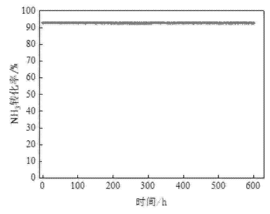
Resumen de: CN121797347A
0001 本申请公开了一种Ru合金单原子催化剂及其制备方法和在氨分解制氢中的应用,属于催化剂制备技术领域。该催化剂以Fe或Ni为主体金属,通过控制金属间电子耦合及表面原子配位,实现Ru以单原子形式锚定于Fe或Ni金属表面或近表面位点,该催化剂在450 ℃下对氨分解的转化率可达90%以上。该催化剂可通过浸渍‑表面置换法结合低温氢还原法制备,工艺简单,易于规模化。Ru原子与Fe或Ni之间形成稳定的Ru–Fe(或Ru–Ni)配位键,能够有效降低氨分解中N–H键断裂能垒,显著提高氨分解活性与抗烧结稳定性。本申请实现了在极低贵金属用量下的高效氨分解制氢,具有良好的成本优势和工业应用前景。
Resumen de: CN121802437A
0001 本发明提供了一种非纯水制氢、氧电解气体发生装备,包括:多个环形极框,所述环形极框的外侧壁上设置有定位夹紧结构;相邻的所述环形极框之间设置有密封垫片;所述环形极框的两侧分别设置有固定环和环形槽;所述环形极框上设置有气液流道和电解液流道,所述气液流道和电解液流道沿环形极框的径向相对布置,所述气液流道由多个呈扇形分布的气液孔道组成,所述环形极框的内孔为电解小室,气液孔道呈锥形且细端与电解小室连通;电解小室中设置有选择性离子交换膜,所述选择性离子交换膜两侧均设置有电极,且相邻的环形极框之间的电极之间设置有主极板。解决了非纯水制氢、氧电解气体发生装备的腐蚀、定位错位、电解效率低、电解液分布不均的问题。
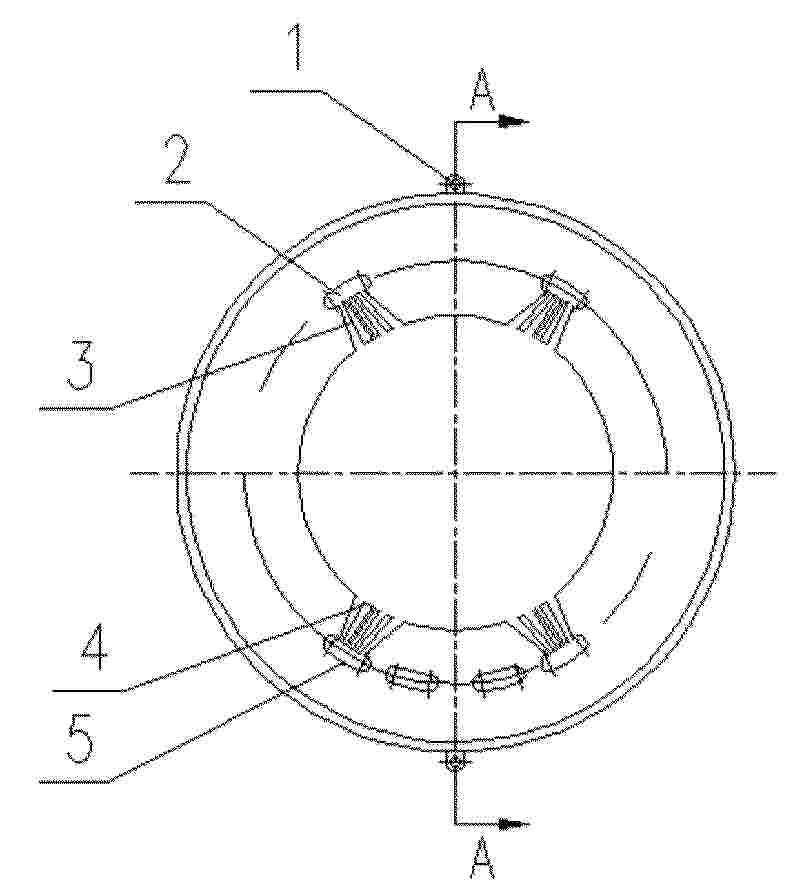
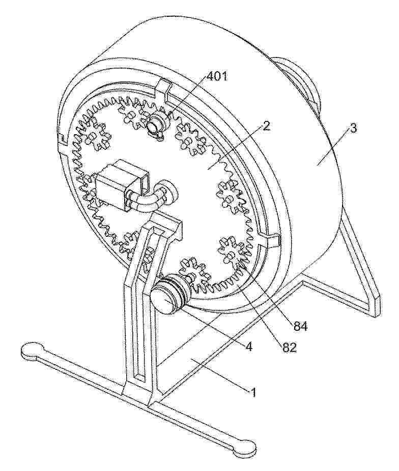
Resumen de: CN121800308A
0001 本发明涉及纳米气泡制备领域,尤其涉及一种基于纳米气泡制备富氢水的装置。本发明提供一种基于纳米气泡制备富氢水的装置,能够使得纳米氢分子气泡与水能够更加充分和更加均匀地接触而形成氢水,以便于提高水的溶氢速率和含氢量,还能及时补充消耗的氢气,提高氢水的制备效率。一种基于纳米气泡制备富氢水的装置,包括有主支撑架、侧边圆板和旋转圆框等;主支撑架上固定连接有侧边圆板。旋转圆框转动带动翻搅板转动,从而翻搅架和翻搅板能够对旋转圆框内部的水和纳米氢分子气泡进行混合搅动,使得纳米氢分子气泡能够与水充分接触而形成氢水,以便于提高水的溶氢速率。
Resumen de: CN121797330A
一种基于熔盐法合成Ga掺杂NiTiO3光催化剂的方法,它涉及一种光催化剂的制备方法。它是要解决现有的溶胶/凝胶法合成的Ga‑NiTiO3光催化全水分解制氢的产氢速率低的技术问题。本方法:将Ga2O3、NiO和TiO2研磨混合均匀,再与由KCl与NaCl混合而成的助熔剂研磨混合均匀,得到前驱体;前驱体煅烧后、用水洗去熔盐和杂质,再过滤干燥,得到Ga掺杂NiTiO3光催化剂。该光催化剂全水分解制氢时的产氢和产氧速率分别达到10.2和4.9 μmol·h‑1,比溶胶凝胶法合成的Ga‑NiTiO3和未掺杂的NiTiO3分别提高了5.6和2.4倍,且具有稳定性和重复使用能力,可用于光催化产氢领域。
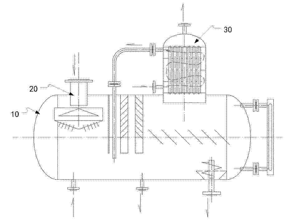
Resumen de: CN121797025A
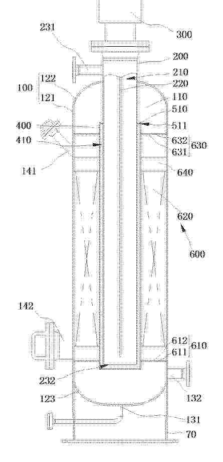
0001 本申请公开了一种气液分离设备和电解制氢系统,用于分离电解制氢系统中的气液,气液分离设备包括:腔体组件和分离组件;腔体组件包括:容纳腔体,容纳腔体被构造具有气液进口、液体出口和气体出口;其中,气液进口被构造于容纳腔体的顶部;分离组件包括:喷淋管道、导流挡片和气流通道,喷淋管道竖直设置于容纳腔体内,气流通道连通喷淋管道和气液进口;导流挡片位于喷淋管道内,以使得导流挡片和喷淋管道之间形成气液挤压空间;喷淋管道的出液端设置有多个喷淋口。本技术方案,能够对气液混合物进行至少三次的气液分离,以大大地提高气液分离效率。同时还能对气液混合物进行彻底分离。
Resumen de: CN121802463A
0001 本发明公开单原子负载异质结复合电极、制备方法和电解装置,复合电极包括多孔导电金属基底、二氧化锰层、钴锰复合金属氧化物异质结层和铱(Ir)单原子活性中心层,二氧化锰层负载在所述多孔导电金属基底表面;在所述二氧化锰层上原位生长形成的钴锰复合金属氧化物异质结层,所述钴锰复合金属氧化物异质结层包含Co<3>O<4>和MnO<2>;以原子级分散形式负载在所述钴锰复合金属氧化物异质结层表面的铱活性中心层。制备方法用于制备本复合电极,电解装置利用根本复合电极作为阳极,本复合电极、制备方法和电解装置,解决了PEM电解水阳极催化剂铱用量高、利用率低、电荷传输慢、稳定性不足的难题。
Resumen de: CN121802481A
0001 本发明涉及阴离子交换膜电解水系统领域,具体涉及一种阴离子交换膜电解水系统用停机保护系统及其保护方法。一种阴离子交换膜电解水系统用停机保护系统,包括:电解槽;碱液循环回路;纯水供给单元,所述纯水供给单元通过所述碱液循环回路对电解腔室内输送纯水以置换和/或稀释电解槽内残留的碱液;监测组件,所述监测组件设于所述电解槽的一侧,所述监测组件与所述碱液循环回路、纯水供给单元和电解槽内的电解系统均通过电信号相连接。本申请通过监测组件实时获取电解系统运行状态,当监测到停机状态时,触发纯水供给单元通过碱液循环回路向电解腔室输送纯水,避免膜因碱液作用发生降解,有效保护阴离子交换膜的结构完整性。
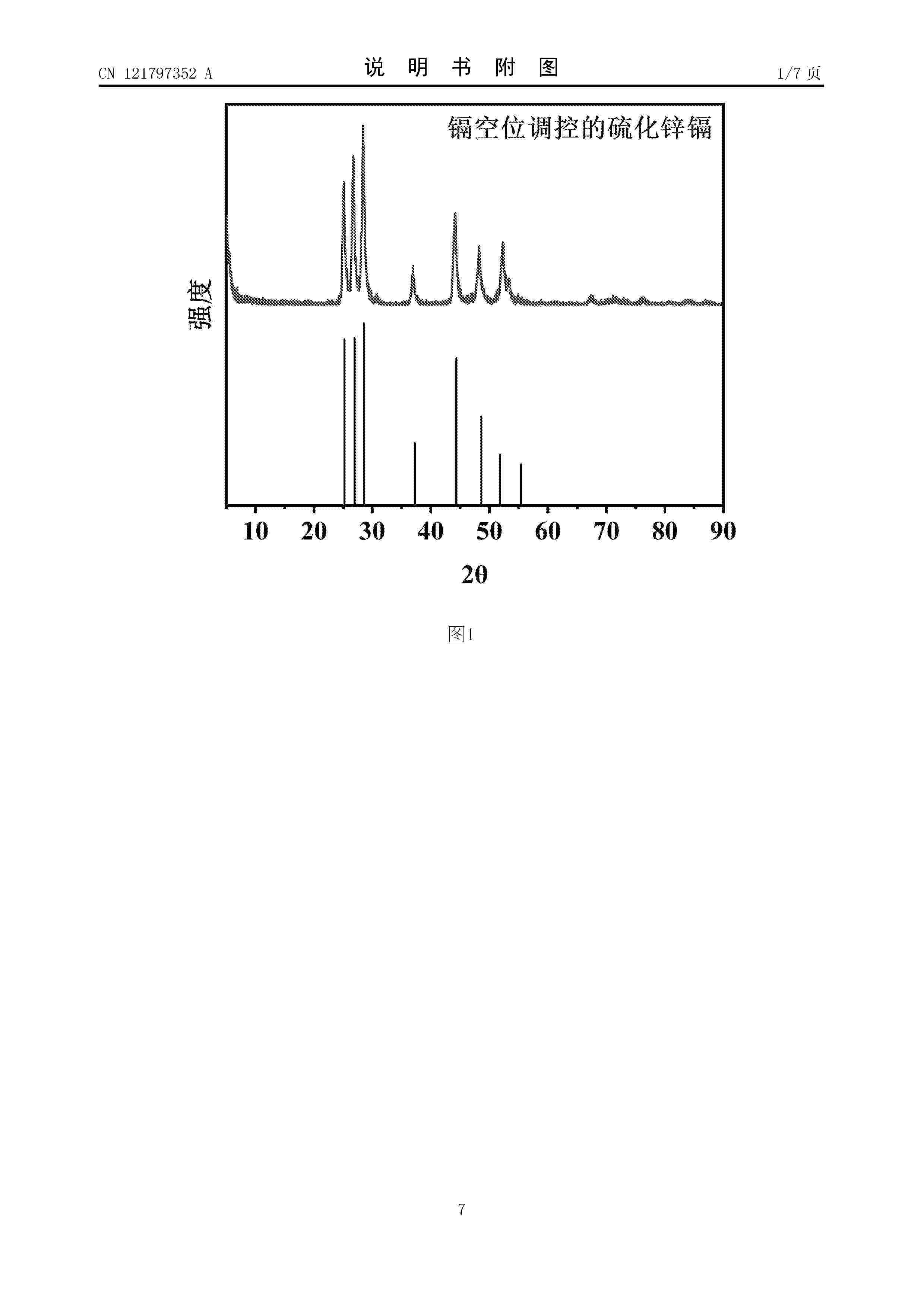
Resumen de: CN121797352A
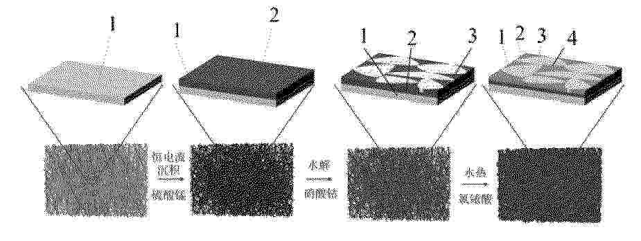
本发明涉及光催化析氢领域一种镉空位调控的硫化锌镉催化剂的制备及其应用。本发明的目的是提供一种制备工艺简便、成本低廉且具有高效光催化析氢性能的镉空位调控的硫化锌镉催化剂,以提升光催化析氢效率,缓解当前能源危机下对清洁能源的迫切需求。所采用的方法:以醋酸锌、氯化镉、硫脲、聚乙烯吡咯烷酮和水合肼溶液为原料,采用一步水热合成方法,制备了镉空位调控的硫化锌镉催化剂可适用于光催化析氢领域且具有较高的催化活性和稳定性。
Resumen de: CN121803088A
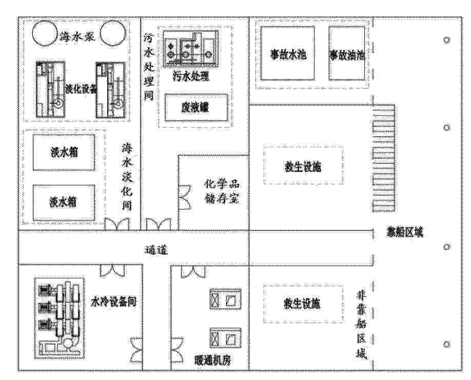
0001 本发明公开了海洋绿色能源领域的一种海上制氢储氢储能一体化平台,旨在解决现有技术中如何在空间受限的海上平台整合工艺特性与安全等级不同的海水淡化、电化学储能、高压电解制氢及储氢等模块的问题。其包括厂房主体,所述厂房主体包括从低到高分层设置的海水淡化工序区、储能工序区、制氢工序区和储氢工序区;所述海水淡化工序区设有靠船平台和远离所述靠船平台设置的海水淡化间;所述储能工序区间隔设有储能间和换流间;所述制氢工序区设有氢气电解间和氢气纯化间;所述氢气纯化间用于对氢气电解间制取的氢气进行纯化处理;本发明适用于将海上风电场的电能进行储存与平台供电,利用海水进行海上制氢并将制备的氢能源储存至海上平台。
Resumen de: CN121797382A
本发明公开了一种高产氢活性的RNCDs/g‑C3N4光催化材料及其制备方法与应用,制备方法包括以下步骤:将芦竹、尿素和过氧化氢加入到去离子水中进行水热反应,得到碳点RNCDs;将尿素在真空、且氮气保护下进行煅烧,得到g‑C3N4;将g‑C3N4溶于去离子水中,加入碳点,超声至完全溶解后进行煅烧,得到RNCDs/g‑C3N4光催化材料。本发明以废弃芦竹这一生物质为原料,通过尿素辅助可控水热法制备氮掺杂高结晶度碳点,再采用原位煅烧法将其负载于g‑C3N4纳米片上,构建出三维分级结构的RNCDs/g‑C3N4光催化材料,该材料在可见光下展现出卓越的光催化析氢性能。
Resumen de: CN222499404U
The utility model provides an AEM water electrolysis electrode and a water electrolysis device. The AEM water electrolysis electrode comprises a catalyst carrier, the catalyst is formed on the catalyst carrier; the gas dredging channel is arranged on the catalyst carrier, and at least part of the surface of the catalyst carrier is exposed through the gas dredging channel. The water electrolysis electrode provided by the utility model can be applied to a water electrolysis device, and has the advantages of high catalytic activity and low energy consumption.
Resumen de: JP2026058843A
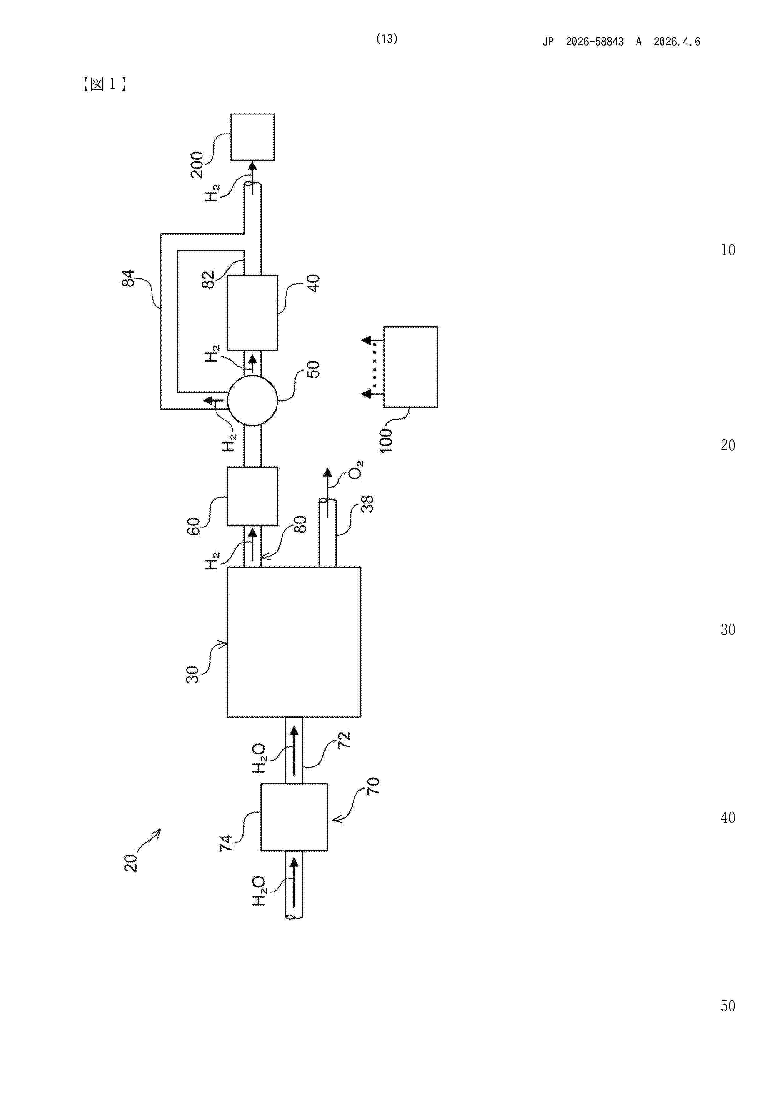
0001 【課題】水素発生材料から水素を発生させる構成において、水素発生サイクルを短くすることが可能な技術を提供する。 【解決手段】水素生成装置は、特定波長の光を受けることによって水素を発生し、水の供給によって水素発生機能を再生可能な水素発生材料を収容する容器と、前記水素発生材料に前記光を付与する光付与部と、前記水素発生材料に水を供給する水供給部と、前記光付与部と前記水供給部とを制御し、前記光の付与によって前記水素発生材料から水素を発生させる水素発生モードと、前記水の供給によって前記水素発生材料の水素発生機能を再生させる再生モードとを実行可能なように構成される制御部と、を備える。 【選択図】図1
Nº publicación: KR20260046150A 06/04/2026
Solicitante:
린데게엠베하
Resumen de: WO2025045387A1
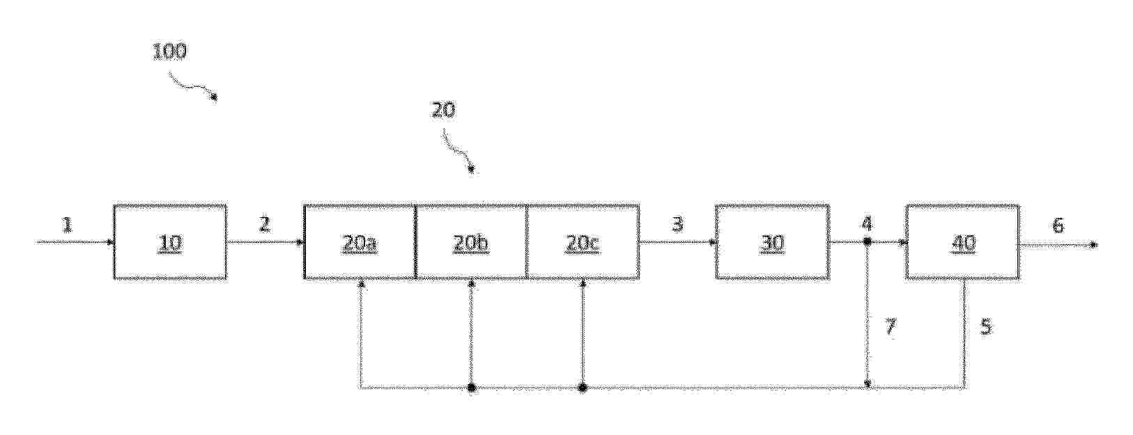
The invention relates to a method and a system (100) for producing a hydrogen-containing product, wherein ammonia (2) is reacted in an ammonia cracker (20) to which heat is supplied, wherein the ammonia cracker (20) has a catalyst bed with at least two catalyst segments (20a, 20b, 20c), wherein in a first catalyst segment (20a) a fraction of the ammonia (2) is reacted at a first minimum temperature (T1) using a first catalyst and in a second catalyst segment (20b), which is downstream of the first catalyst segment (20a), a further fraction of the ammonia (2) is reacted at a second minimum temperature (T2) using a second catalyst. The invention is characterised in that the first minimum temperature (T1) is lower than the second minimum temperature (T2).
 BOPI
BOPI
 Sede Electrónica