Si deseas distinguir tus productos, servicios o ambos de los de otra empresa, es posible que necesites una marca o nombre comercial. Descubre qué son, en qué consiste su procedimiento de registro y qué implica.

Información sobre los plazos de presentación de solicitudes de transformación de marcas de la Unión Europea en marca nacional española. Más información


Si tienes un nuevo dispositivo, producto o procedimiento que resuelva un problema técnico o tenga una ventaja práctica, existen distintas formas de protegerlo en España y en otros países. Descubre cómo hacerlo.

¿Tu innovación reside en la estética, la ornamentación o la apariencia de tu producto? Protégela mediante un diseño industrial. Descubre qué derechos confiere el registro y cómo realizar la tramitación.

Las indicaciones geográficas protegen el nombre de un producto originario de una zona geográfica, a la cual le debe una determinada calidad, reputación u otra característica. Descubre qué son, en qué consiste su procedimiento de registro y qué beneficios conceden.

Las patentes publicadas en todo el mundo son una valiosa fuente de información científica, técnica y comercial.

Si eres emprendedor/a o una empresa y quieres potenciar y mejorar la rentabilidad de tu negocio protegiendo de forma adecuada los activos intangibles de tu organización, en este espacio encontrarás lo necesario.


 953
resultados
953
resultados
 Última actualización
15/03/2026 [07:16:00]
Última actualización
15/03/2026 [07:16:00]


 Resultados 325 a 350 de 953

Resumen de: CN120882906A
A porous transport layer for an electrolytic cell or for a fuel cell, the porous transport layer comprising: a first non-woven layer having metal fibers, the first non-woven layer having metal fibers being arranged for contacting a proton exchange membrane, where the first non-woven layer having metal fibers comprises metal fibers having a first equivalent diameter, and the second non-woven layer having metal fibers having a second equivalent diameter; wherein the first non-woven layer having metal fibers has a first surface roughness and a first porosity,-a second non-woven layer having metal fibers wherein the second non-woven layer having metal fibers comprises metal fibers having a second equivalent diameter, wherein the second nonwoven layer having metal fibers has a second surface roughness and a second porosity wherein the first surface has a material ratio of less than 5% material at a height of 5 mu m and greater than 70% material at a depth of-5 mu m, the first equivalent diameter is less than the second equivalent diameter, the first surface roughness is at least 20% less than the second surface roughness, and the second surface roughness is at least 20% less than the second surface roughness. The first porosity is at least 10% less than the second porosity, such as in the range of 20% to 120%, for example, the first porosity is at least 10% less than the second porosity, such as in the range of 10% to 50%, and wherein the first nonwoven layer is metallurgically bo

Resumen de: CN121039917A
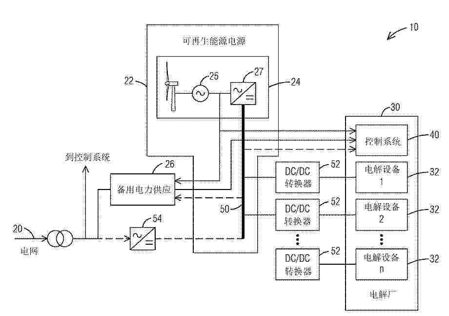
Systems and methods are provided for an electrolysis plant interconnecting a renewable energy source (22) and a power grid (20). The system includes a power source (22) and an electrolysis plant (30) including electrolysis equipment (32) connected to the power source (22) to energize the electrolysis equipment to respective operating conditions. The control system (40) is connected to the power source (22) and the power grid (20). Upon detection of a power failure or otherwise insufficient power supply of the renewable power source, the control system is configured to bring the electrolysis device to a corresponding standby condition. The electrolysis device is connected to an electrical grid to energize the electrolysis device to a standby condition. Optionally, a backup power supply (26) is connected to the control system such that the backup power supply is configured to energize the control system upon detecting that the renewable power source and the grid are simultaneously powered off or are simultaneously otherwise insufficient in power supply.
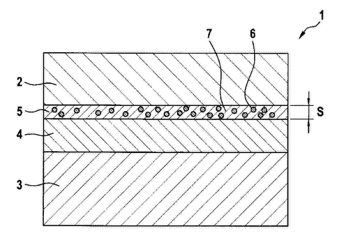
Resumen de: CN120958177A
The invention relates to a membrane electrode assembly (1) having an anode (2), a cathode (3) and a hydrocarbon membrane (4) between the anode (2) and the cathode (3). The membrane electrode assembly (1) further comprises a protective layer (5) arranged between the anode (2) and the hydrocarbon membrane (4) and-or between the cathode (3) and the hydrocarbon membrane (4), where the protective layer (5) comprises at least one ceramic material (6) and a fluorine-containing ionomer (7), where the ceramic material (6) is dispersed in the fluorine-containing ionomer (7).
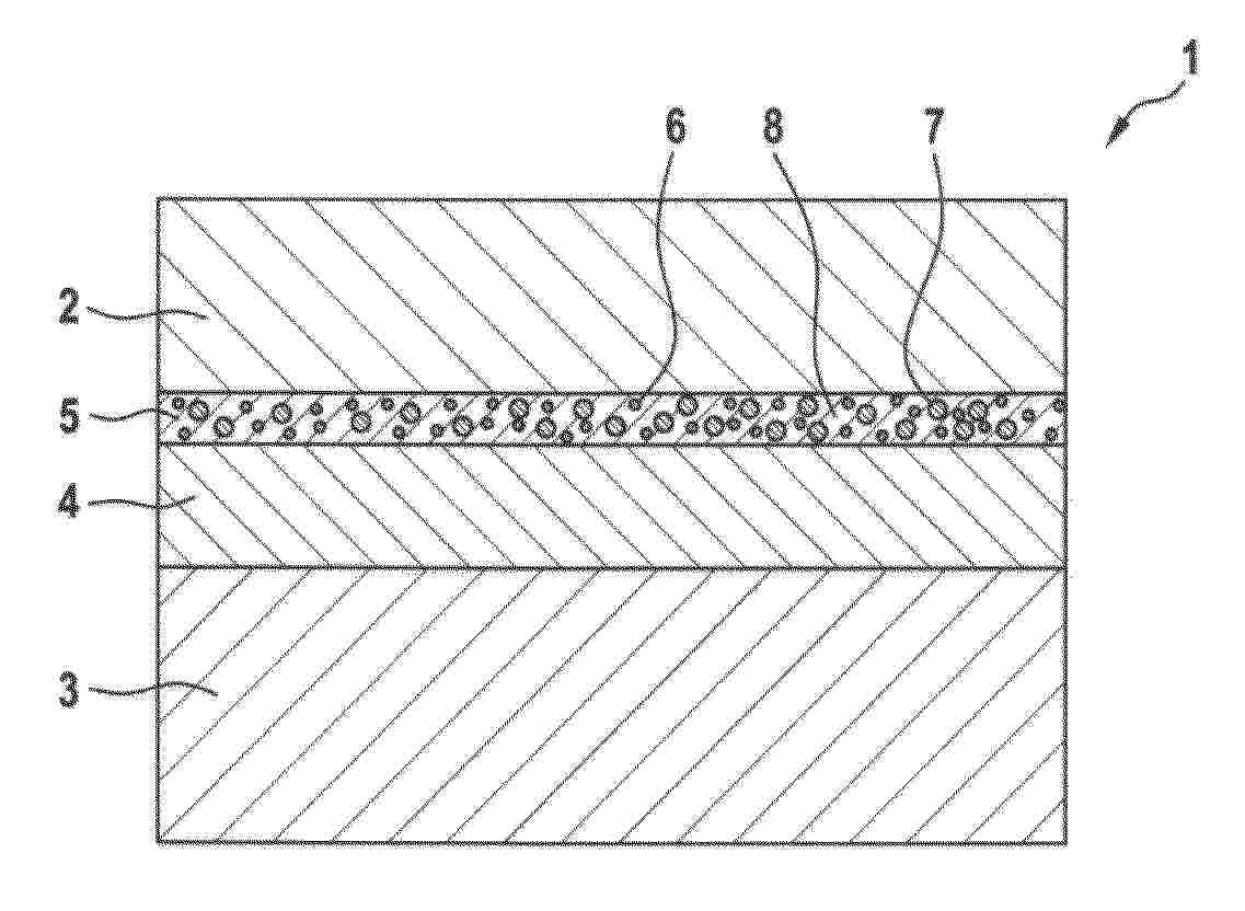
Resumen de: CN121013925A
The invention relates to a membrane electrode assembly (1) for a water electrolyser, comprising an anode (2), a cathode (3) and a hydrocarbon membrane (4) located between the anode (2) and the cathode (3), further comprising a first gas recombination layer (5) arranged between the anode (2) and the hydrocarbon membrane (4) wherein the first gas recombination layer (5) comprises a noble metal (6), a ceramic material (7) and a proton conducting polymer (8), and wherein the volume fraction of the proton-conducting polymer (8) is 24 to 84 vol%, in particular 35 to 75 vol%, and in particular 46 to 65 vol%, based on the total volume of the gas recombination layer (5).
Resumen de: CN120981610A
The invention relates to a membrane electrode assembly (1) for a water electrolyser, comprising an anode (2), a cathode (3) and a hydrocarbon membrane (4) located between the anode (2) and the cathode (3), further comprising a first gas recombination layer (5) arranged between the anode (2) and the hydrocarbon membrane (4), in which at least one adhesion layer (6) is arranged between the gas recombination layer (5) and the hydrocarbon membrane (4), wherein the adhesive layer (6) comprises at least one ceramic material (7) and a proton-conducting polymer (8).
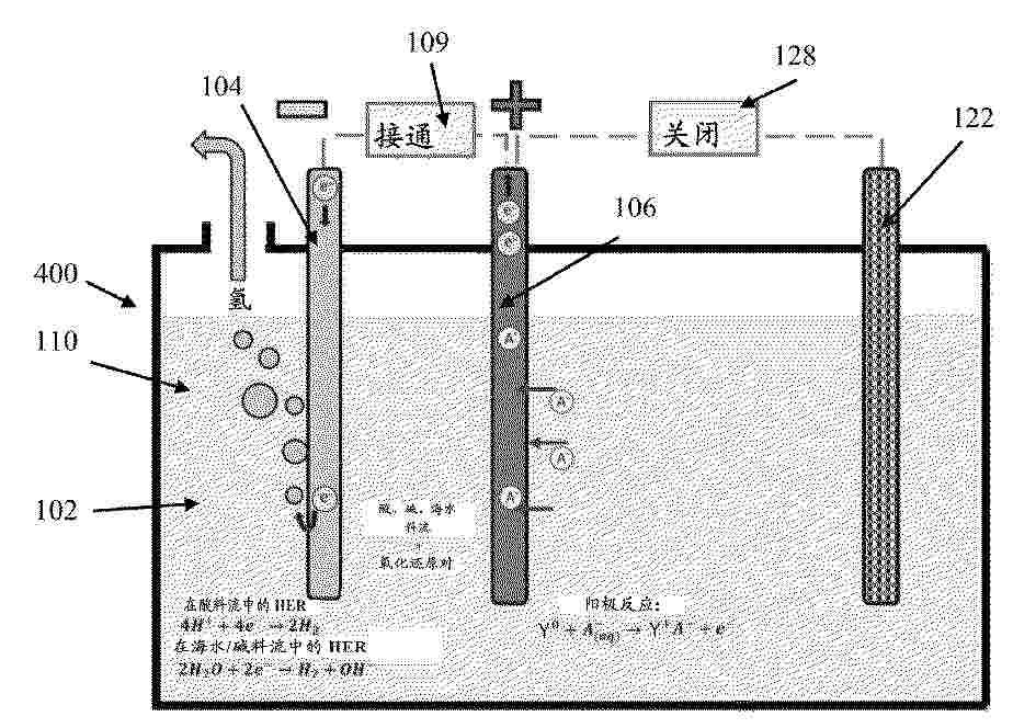
Resumen de: CN120981421A
A hydrogen production system comprising: a first electrode having an electrocatalyst, a second electrode having an electron donor material comprising a plurality of active sites, the second electrode configured to release electrons from the active sites within a predetermined working potential range below a working potential triggering an oxygen evolution reaction; a first electrolyte in contact with the first and second electrodes, the electrolyte being a source of hydrogen protons; and a power source configured to provide the system with the predetermined operating potential range to release electrons from the second electrode and transfer electrons to the first electrode such that hydrogen protons combine with the electrons to produce hydrogen gas.
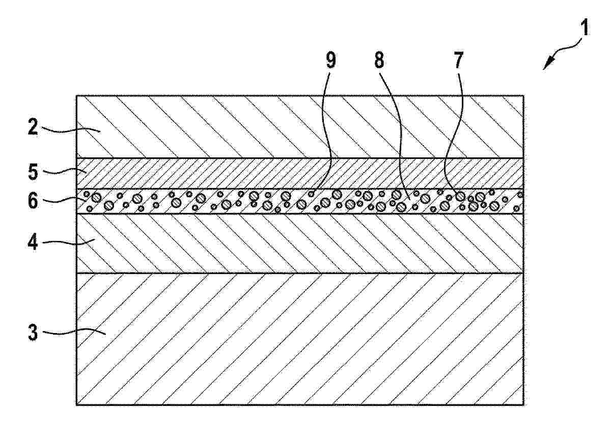
Resumen de: EP4692424A1
It is an object of the present invention to provide a steam electrolysis device and a steam electrolysis method, which have high energy efficiency. The present invention relates to: a steam electrolysis device, comprising an anode electrode chamber, a cathode electrode chamber, and an ion conductor disposed between these electrode chambers, wherein steam in an amount more than twice the amount of hydrogen generated is supplied to at least one selected from the anode electrode chamber and the cathode electrode chamber, and 50% or less of the supplied steam is electrolyzed; and a steam electrolysis method using the steam electrolysis device.
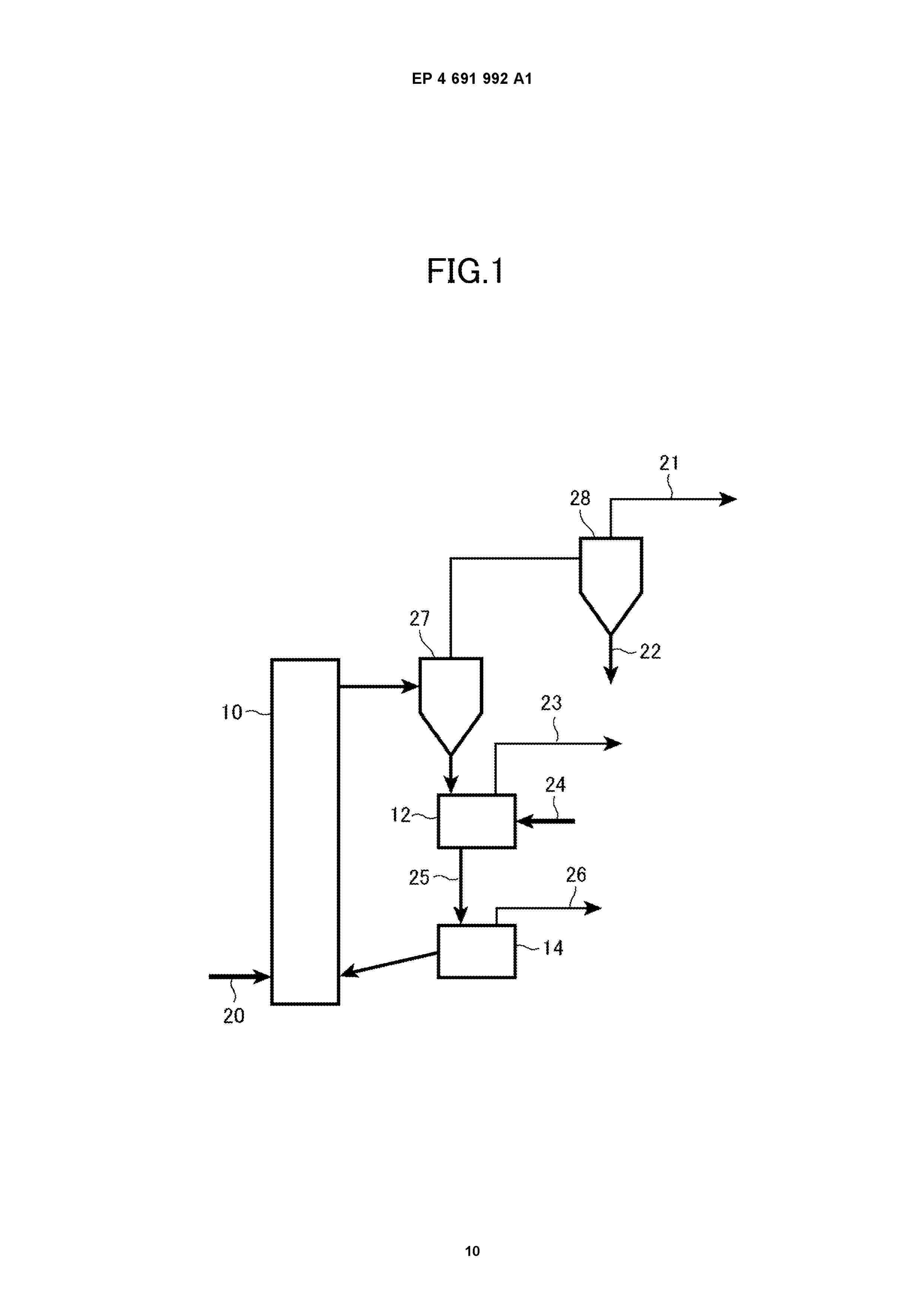
Resumen de: EP4691992A1
Provided is a method for producing a highly active oxygen carrier at low cost, and a method for producing hydrogen and an apparatus for producing hydrogen using the highly active oxygen carrier.SolutionA method for producing an oxygen carrier of the present invention is a method for producing an oxygen carrier formed of an activated iron titanate containing an alkali titanate and an iron oxide by calcining a mixture of iron titanate particles and an alkali component. The mixture of the iron titanate particles and the alkali component is prepared by any of: physically mixing the iron titanate particles and an alkaline compound; and spraying an aqueous solution of the alkaline compound to the iron titanate particles or impregnating the iron titanate particles with the aqueous solution of the alkaline compound and then drying the sprayed or impregnated iron titanate particles.
Resumen de: EP4693486A1
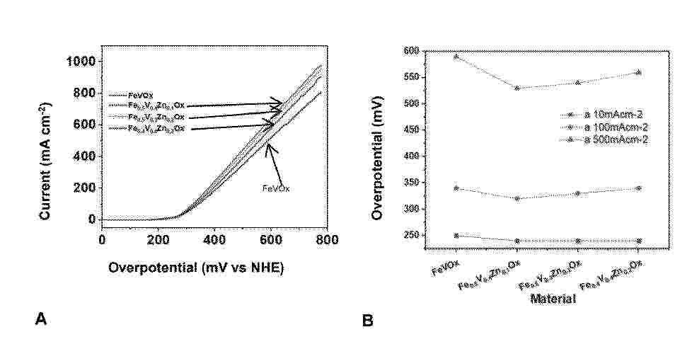
The invention relates to an electrocatalytic electrode comprising a coating film on an electrically conductive base substrate that includes a non-stoichiometric mixed oxide dispersed in the film, including a mixture of iron and vanadium, in a metal-organic matrix, the organic part of which includes the mixed oxide dispersed therein. The electrocatalytic electrode can be used for the production of molecular hydrogen.The invention also relates to a method for producing the electrocatalytic electrode and the use of the electrocatalytic electrode for the improved production of molecular hydrogen by means of at least water hydrolysis, alkaline water electrolysis, alkaline electrolysis via ion exchange, as a selective electrode and as an electrode for the oxidation of organic compounds in an aqueous solution.
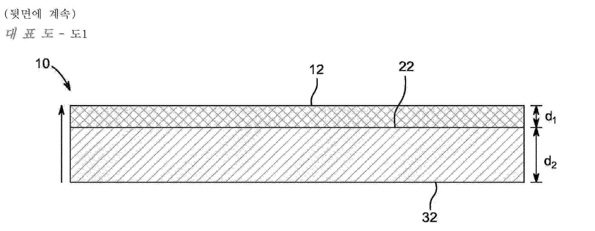
Resumen de: CN121013921A
The invention provides a porous transport layer for an electrolytic cell or for a fuel cell, the porous transport layer comprising:-a first non-woven layer having metal fibres, the first non-woven layer having metal fibres being arranged for contacting a proton exchange membrane, wherein the first non-woven layer having metal fibers comprises metal fibers having a first equivalent diameter, and wherein the first non-woven layer having metal fibers has a first surface roughness and a first porosity; -a second non-woven layer having metal fibers, where the second non-woven layer having metal fibers comprises metal fibers having a second equivalent diameter, where the second non-woven layer having metal fibers has a second surface roughness and a second porosity, where the first surface roughness is less than 10 mu m, and the second surface roughness is less than 10 mu m. The first equivalent diameter is less than the second equivalent diameter, the first surface roughness is at least 20% less than the second surface roughness, e.g. In the range of 20% to 120%, where the first porosity is at least 10% less than the second porosity, e.g. In the range of 10% to 50%, and where the first nonwoven layer is metallurgically bonded to the second nonwoven layer.
Resumen de: WO2024208792A1
A methanol plant and a process for the production of methanol is provided. A hydrogen recovery section receives off-gas stream from the methanol synthesis section and outputs a hydrogen-rich stream, which is recycled upstream the methanol synthesis section.
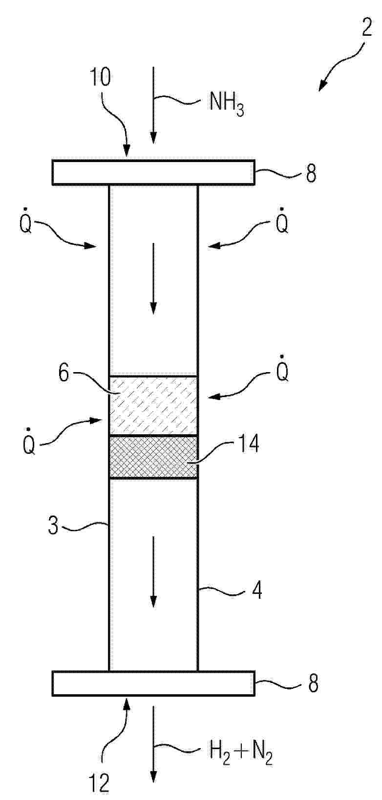
Resumen de: EP4691968A1
A process (100) for producing a hydrogen product (20) from a feedstock stream (10), the process (100) comprising the following steps:- performing a combustion of a fuel gas (S11) to bring a heat input to the process (100) thereby generating a flue gas (52),- pre-heating the ammonia stream (S3), said preheating being realized in a first heat exchanger (4) arranged to heat the ammonia stream by heat exchange with the flue gas,- sending the pre-heated ammonia stream (12) to a vaporizer (5) and vaporizing (S4) said pre-heated ammonia stream,- sending the vaporized ammonia (14) from said vaporizer (5) as said feedstock stream (S6) and/or sending the vaporized ammonia from said vaporizer as said fuel to said combustion (S11).
Resumen de: EP4691970A1
The invention relates to a process for producing a hydrogen product (3) from a feedstock stream (4), said process comprising the following steps:- providing an ammonia stream (8);- sending the ammonia stream (8) to a vaporizer (6) configured to receive said ammonia stream (8) and to vaporize said ammonia stream (8) so as to obtain a vaporized ammonia stream (10); and- controlling the temperature of the vaporized ammonia stream (10) by injecting a cooling medium (16) into the vaporized ammonia stream (10) thereby obtaining a temperature-controlled ammonia stream (18).
Resumen de: EP4692422A1
The present invention relates to an electrode for the electrolysis of, in particular, alkaline water solutions. The electrode has a 3D-knitted metal structure in the form of a net. The metal is predominantly made of nickel. The invention also relates to a corresponding electrolysis cell and its use for the electrolysis of alkaline aqueous solutions.
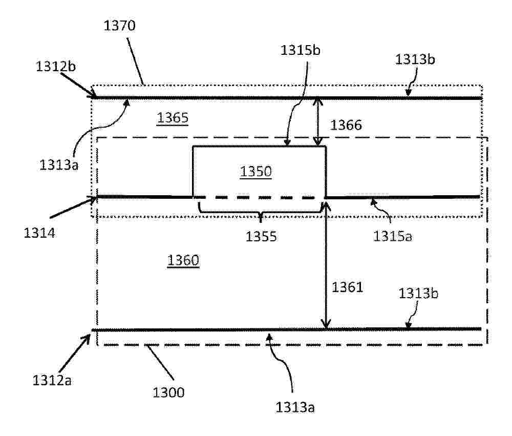
Resumen de: CN120936755A
The present application relates to an electrolytic cell battery cell having a battery layer (1314) comprising an electrochemically active battery region (1350), the battery layer (1314) having a first side (1315a) and a second side (1315b). The cell defines a first fluid flow region (1360) for delivering fuel to the first side (1315a) of the cell layer (1314) and a second fluid flow region (1365) for discharging fluid from the second side (1315b) of the cell layer (1314). A cross-sectional area of the second fluid flow region (1365) is less than a cross-sectional area of the first fluid flow region (1360).
Resumen de: WO2025002798A1
The invention relates to a reactor (2) for generating hydrogen and at least one other product from at least one reactant, the reactor comprising a tubular reactor vessel (4) which contains a catalyst (6) in the form of a ceramic bed. Improved corrosion resistance against a variety of media and thus an increased service life of the reactor (2) is achieved by forming the reactor vessel (4) from silicon-infiltrated silicon carbide (SiSiC).
Resumen de: US20260035242A1
A hydrogen generation system with controlled water distribution is disclosed. The system comprises a reaction chamber containing a hydrogen-producing fuel, a liquid distribution mechanism, and a control system. The liquid distribution mechanism includes a rotating arm with liquid injection ports that move vertically through the fuel chamber. This allows for precise and efficient liquid delivery to unreacted fuel, optimizing hydrogen production. A proprietary fuel blend utilizes chemicals that store significant amounts of hydrogen in a solid-state form. A feature of the device is the arm's controlled vertical movement, achieved through a screw mechanism that adjusts the arm's height as it rotates, creating a spiral liquid distribution pattern. The control system regulates liquid injection rates, arm rotation speed, and vertical movement to optimize hydrogen production based on demand. The system can also operate at low pressures and be scaled to different sizes in a safer, more efficient, on-demand manner.
Resumen de: JP2026020880A
【課題】少なくとも特定の箇所において電極性能に関連する状態のばらつきが少ない水電解用電極を製造する観点から有利な水電解用電極の製造方法を提供する。【解決手段】水電解用電極の製造方法は、下記(I)、(II)、及び(III)を含んでいる。(I)少なくとも1つの導電性基材21上に水電解用電極を形成させるための原料溶液L1を少なくとも1つの導電性基材21が配設された容器11を経由して循環させる。(II)原料溶液L1が少なくとも1つの流路14を通過する。(III)原料溶液L1の流れの下流における流路14の流路断面積が原料溶液L1の流れの上流における流路14の流路断面積よりも小さい状態で原料溶液L1の流れを生じさせる。【選択図】図1
Resumen de: JP2026020857A
【課題】Irを含有しなくても、十分な触媒性能および十分な耐久性を有する新規な水電解陽極触媒を提供する。【解決手段】第四周期以上第六周期以下の第IV、V、VI族元素および第二周期以上第六周期以下のXIV族元素からなる群から選択される少なくとも一種の元素、を含む炭化物、窒化物、およびホウ化物からなる群から選択される少なくとも一種の化合物、を含む水電解陽極触媒。【選択図】なし
Resumen de: JP2026020881A
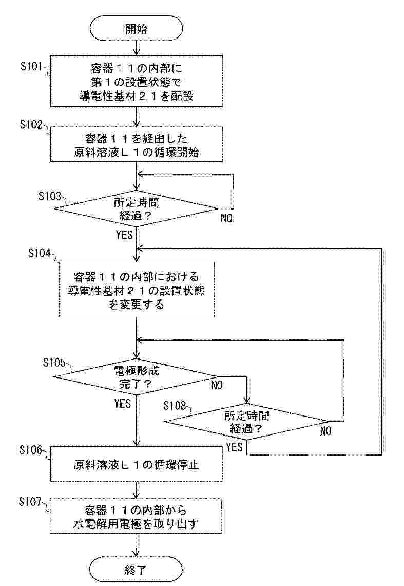
【課題】従来よりも電極性能に関連する状態のばらつきが少ない水電解用電極を製造する観点から有利な水電解用電極の製造方法を提供する。【解決手段】水電解用電極の製造方法は、第1の設置状態及び第2の設置状態において少なくとも1つの導電性基材21上に水電解用電極を形成させるための原料溶液L1を少なくとも1つの導電性基材21が配置された容器11を経由して循環させる。第2の設置状態における少なくとも1つの導電性基材21の向きは、第1の設置状態における少なくとも1つの導電性基材21を、所定の直線を回転軸として半回転させたときの少なくとも1つの導電性基材21の向きと一致する。所定の直線は、少なくとも1つの導電性基材21の主面上の直線又は少なくとも1つの導電性基材の主面と交差する直線である。【選択図】図5
Resumen de: AU2023449815A1
A system and method of making hydrogen from water. A cylindrical reaction vessel is provided with an outer shell, a central shaft, and one or more concentric inner tubes separated by annular spaces. Water is delivered to the annular spaces by a water pump through an inlet defined in the reaction vessel. The water courses along a tortuous flow path. That path begins at an inner annular space around a central shaft. It ends at an outer annular space. The water emerges from the reaction vessel through an outlet associated with a manifold. A high-frequency vibratory stimulus is applied to the reaction vessel and water. Water molecules are dissociated into hydrogen molecules and oxygen atoms. These reaction products are delivered through the manifold along an effluent flow path to a receiving pressure vessel before deployment to a sub-assembly for harnessing clean energy.
Resumen de: CN121497514A
本发明公开了一种基于发动机尾气余热的等离子体氨分解制氢装置,包括发动机、液氨瓶、等离子体氨分解反应器、温度传感器、氢气罐及等离子体电源。发动机运行时,液氨经汽化器汽化为气态氨,一部分进入发动机燃烧,另一部分与发动机尾气换热后进入反应器。同时,温度传感器实时监测尾气温度并反馈至ECU,ECU根据尾气温度输出控制信号到等离子体电源。尾气温度高于700 K时,关闭等离子体电源,依靠热催化实现氨气分解;当尾气温度低于700 K时,触发等离子体电源并进入动态调节模式,采用分阶段上电策略,先低功率预放电保证放电稳定性,再根据需求逐步提升功率。反应器内氨气分解生成氢气和氮气,产物混合气部分储存,部分作为发动机燃料使用。
Resumen de: CN121496410A
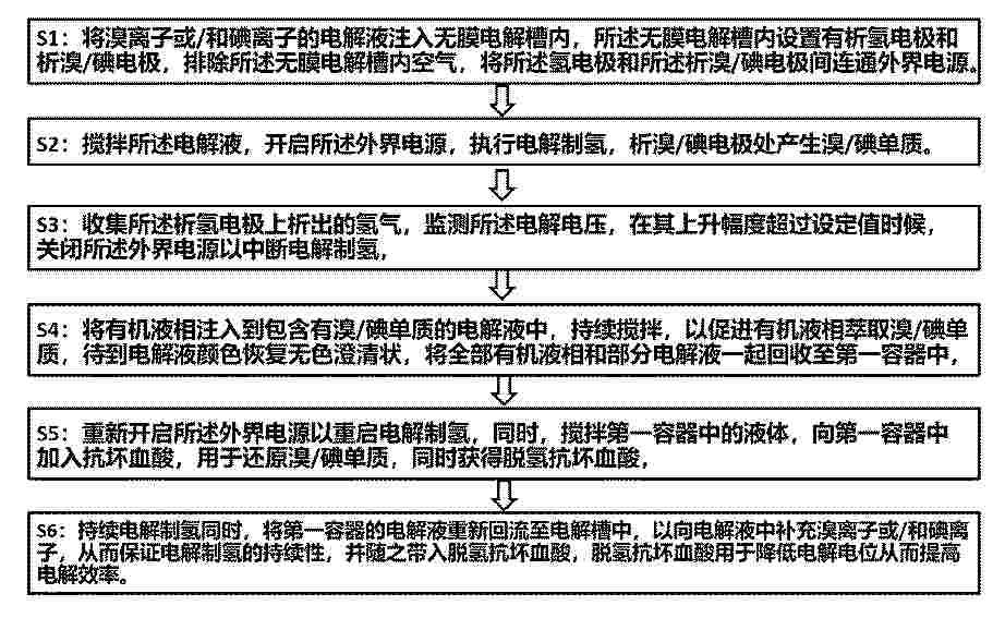
本申请属于氢能源制备领域,具体公开了一种萃取辅助无膜电解水制氢方法及装置,包括:S1将电解液注入无膜电解槽内,S2执行电解制氢,S3收集析氢电极上析出的氢气,监测电解电压,在其上升幅度超过设定值时,中断制氢,S4将有机液相注入到电解液中,以促进有机液相萃取溴/碘单质,后将全部有机液相和部分电解液一起回收至第一容器中,S5重新开启外界电源以重启电解制氢,向第一容器中加入抗坏血酸,用于还原溴/碘单质,同时获得脱氢抗坏血酸,S6持续电解制氢同时,将第一容器的电解液重新回流至电解槽中。本发明同时提供了实现以上方法的装置。本发明方法解决了现有技术中无膜电解水制氢工艺连续循环性不足和制氢效率不足的问题。
Resumen de: CN121496456A
本发明涉及电催化剂合成领域,公开了一种中熵固溶体氧化物的制备方法:将固体无机锰盐、锡盐、铱盐和氯化钠进行研磨,混合后获得金属盐混合物;将金属盐混合物在空气中进行高能球磨处理,形成高度均质化的前驱体;将球磨后的前驱体进行热处理,获得含有氯化钠的固溶体氧化物催化剂;将含有氯化钠的固溶体氧化物催化剂进行水洗处理,获得中熵固溶体氧化物电催化剂。本发明还公开了上述制备得到催化剂及其在酸性溶液中电解水析氧反应和在质子交换膜PEM电解水制氢反应中的应用。该催化剂应用于PEM电解水制氢反应和电解水氧化反应中均展现出优异的电催化活性,且长期工作下仍具有较好稳定性。
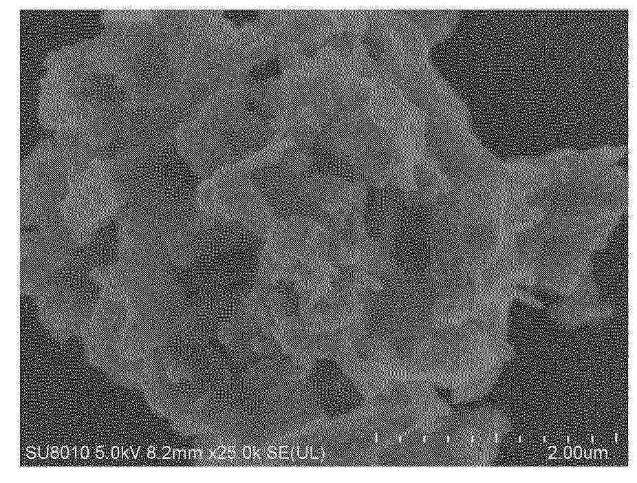
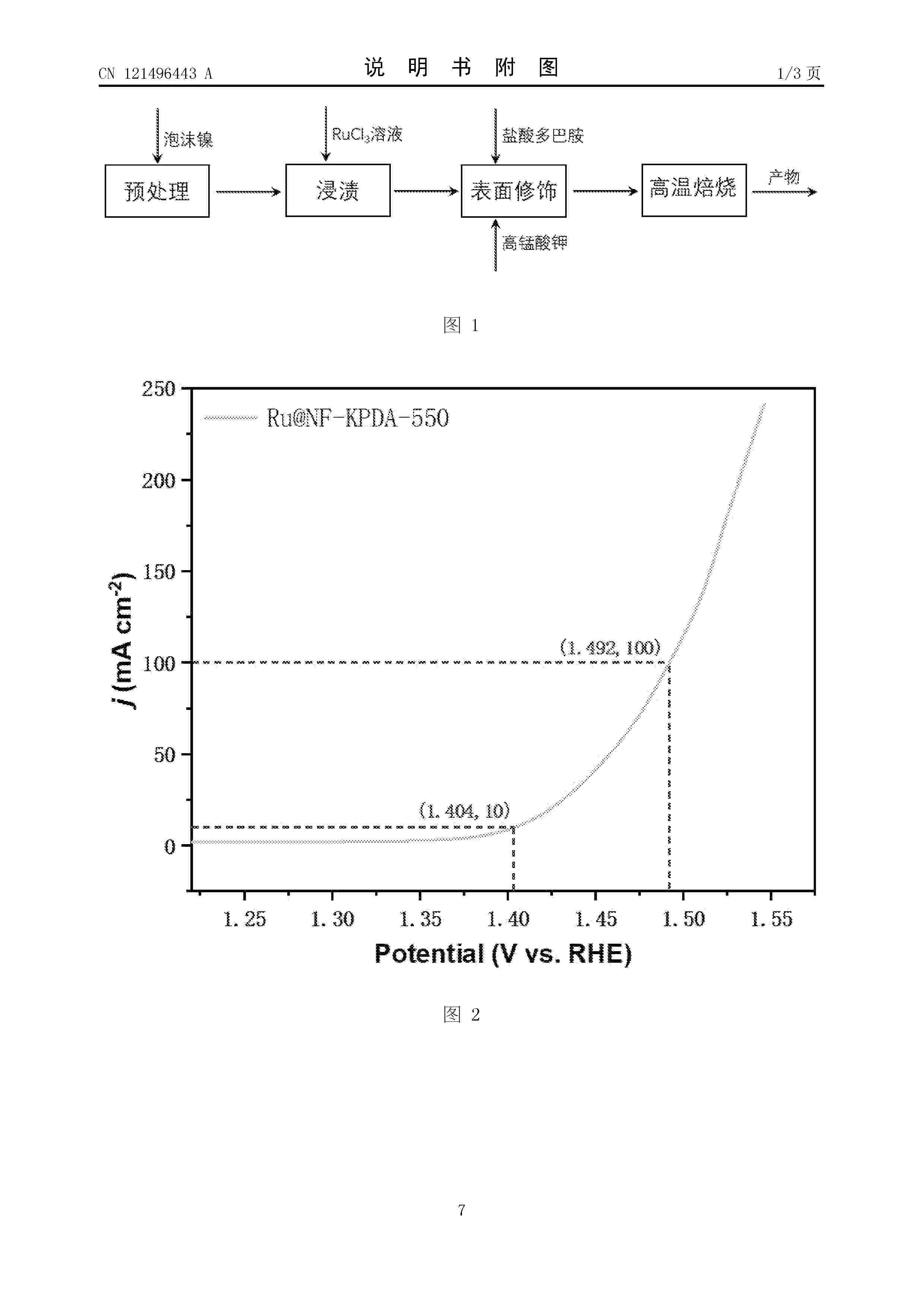
Nº publicación: CN121496443A 10/02/2026
Solicitante:
四川大学
Resumen de: CN121496443A
本发明公开了一种新型酸性电解水析氧反应电催化剂及其制备方法,所述电催化剂为一种以泡沫镍为基底的新型材料,该材料的制备方法是将预处理后的泡沫镍浸渍在RuCl3水溶液中,一定时间后取出再浸渍在高锰酸钾和盐酸多巴胺的氨水溶液中反应,最后在惰性气氛下焙烧制得。本发明提供了酸性电解水析氧反应电催化剂的方法,Ru在泡沫镍基底分散均匀,负载量低,在0.5M H2SO4酸性电解水析氧反应中,在10mA cm‑2电流密度下,过电位仅为174mv,稳定性超过44h。本发明解决了酸性电解质电解水制氢过程中OER催化剂活性较差、稳定性差、成本高的问题。
 BOPI
BOPI
 Sede Electrónica