Si deseas distinguir tus productos, servicios o ambos de los de otra empresa, es posible que necesites una marca o nombre comercial. Descubre qué son, en qué consiste su procedimiento de registro y qué implica.

Información sobre los plazos de presentación de solicitudes de transformación de marcas de la Unión Europea en marca nacional española. Más información


Si tienes un nuevo dispositivo, producto o procedimiento que resuelva un problema técnico o tenga una ventaja práctica, existen distintas formas de protegerlo en España y en otros países. Descubre cómo hacerlo.

¿Tu innovación reside en la estética, la ornamentación o la apariencia de tu producto? Protégela mediante un diseño industrial. Descubre qué derechos confiere el registro y cómo realizar la tramitación.

Las indicaciones geográficas protegen el nombre de un producto originario de una zona geográfica, a la cual le debe una determinada calidad, reputación u otra característica. Descubre qué son, en qué consiste su procedimiento de registro y qué beneficios conceden.

Las patentes publicadas en todo el mundo son una valiosa fuente de información científica, técnica y comercial.

Si eres emprendedor/a o una empresa y quieres potenciar y mejorar la rentabilidad de tu negocio protegiendo de forma adecuada los activos intangibles de tu organización, en este espacio encontrarás lo necesario.


 1500
resultados
1500
resultados
 Última actualización
27/06/2026 [07:57:00]
Última actualización
27/06/2026 [07:57:00]


 Resultados 575 a 600 de 1500

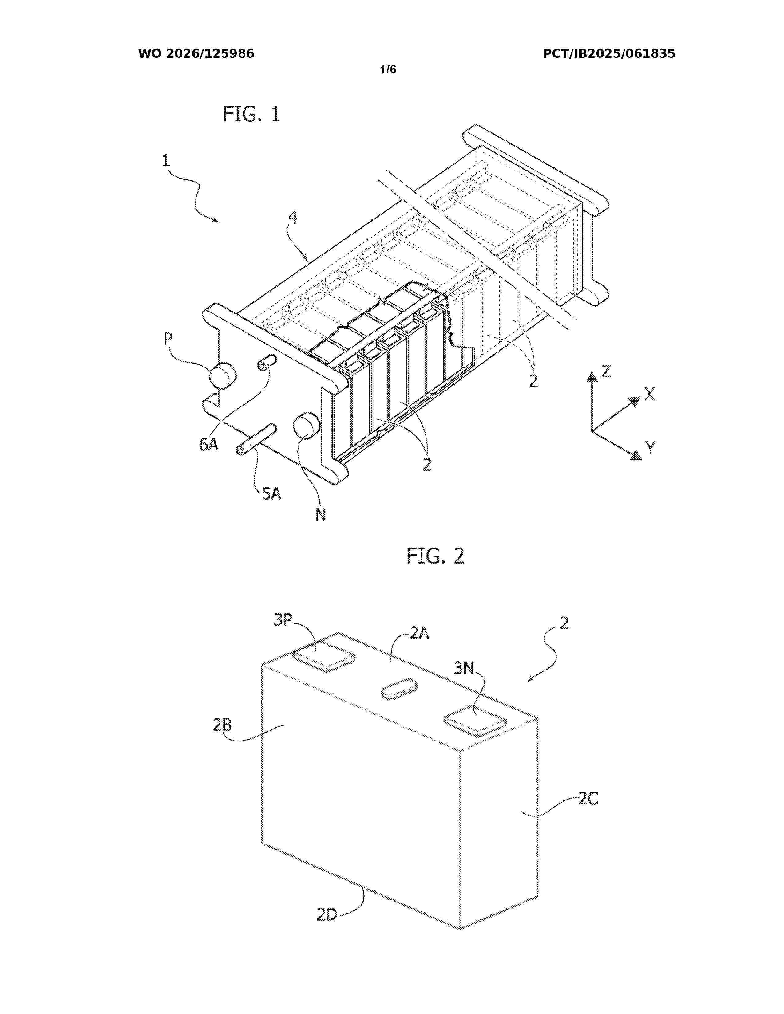
Resumen de: WO2026125986A1
An electric battery unit, for example a battery pack or a single module contained in a battery pack, comprises a housing (4) and a plurality of battery cells (2) within the housing (4), which are configured and arranged to come into direct contact with a flow of a temperature-regulating liquid that passes through the housing (4) for maintaining the battery cells (2) within a determined temperature range. The temperature-regulating liquid flows from an inlet collector chamber (5), which extends below the battery cells (2), through the spaces (7) between the battery cells (2) and up to an outlet collector chamber (6) which extends above the battery cells (2). The inlet collector chamber (5) communicates with the spaces (7) between the battery cells via a plurality of relatively restricted passages (9), which offer the flow of the temperature-regulating liquid sufficient resistance to prevent the temperature-regulating liquid from tending to flow to a greater extent in the spaces that are closer to the inlet and/or the outlet for the temperature-regulating liquid. The inlet collector chamber (5) is defined by the internal cavity of a rigid hollow body (50), constituting an element independent of the structure of the housing (4), disposed inside the housing (4) below the battery cells (2). The rigid hollow body (50) has an inlet (5A) for the temperature-regulating liquid and an upper wall with a distribution of apertures (9) that define said restricted passages.

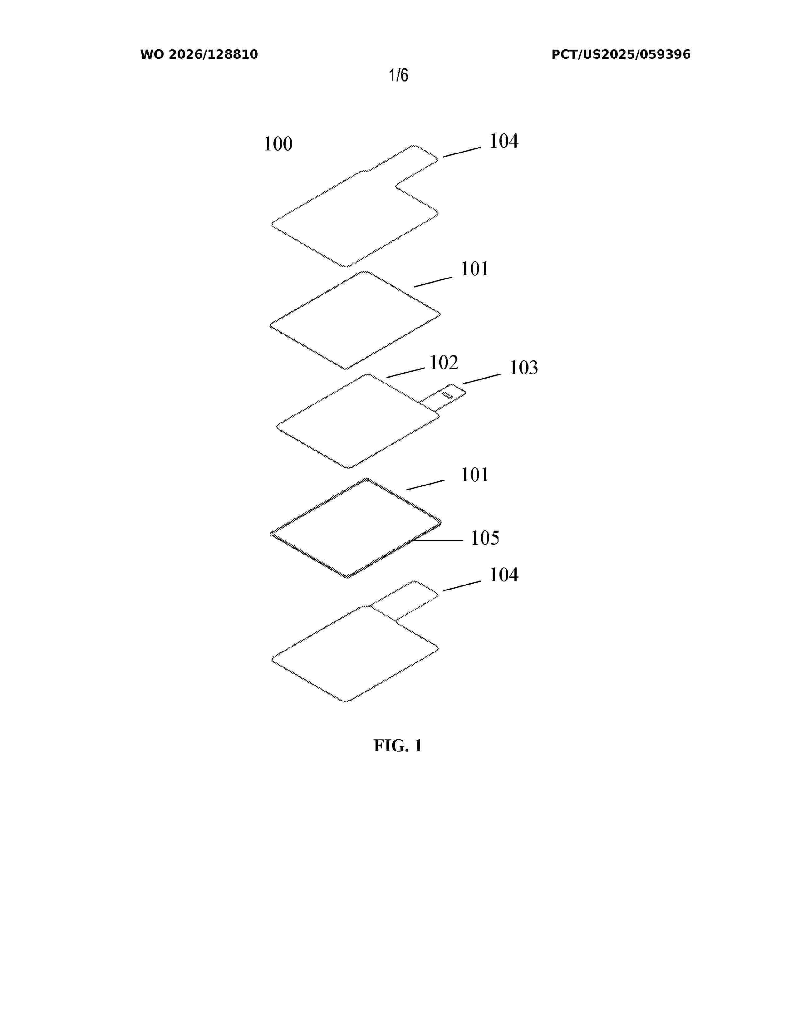
Resumen de: WO2026128810A1
The present disclosure concerns seals and processes of making seals for a cathode and a solid-state electrolyte separator.
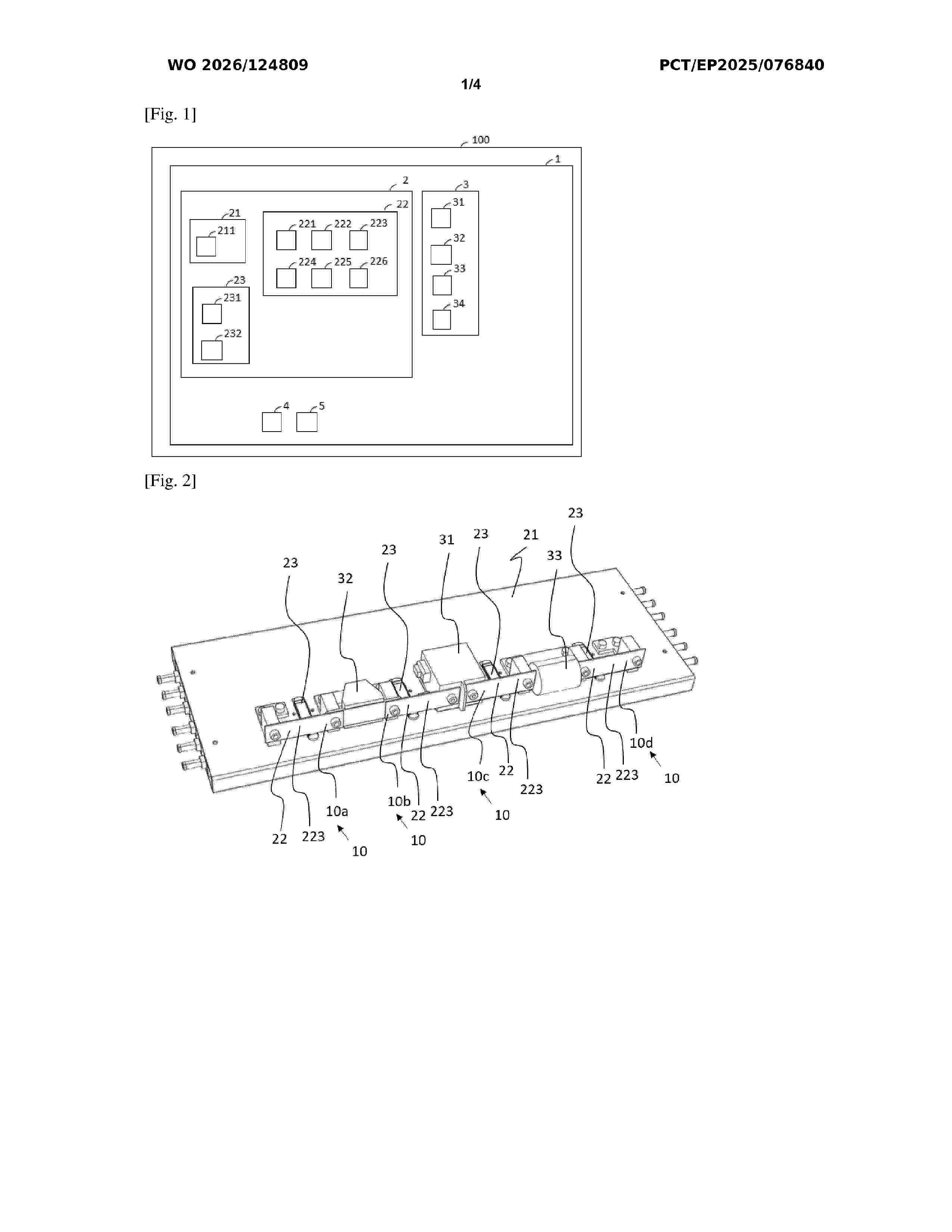
Resumen de: WO2026124809A1
The invention relates to an arrangement (1) comprising an electrical component (32) and a cooling device (2), which cooling device comprises: - a heat sink (21); - a first thermal conductor (22); - a first surface of the first conductor being in contact with a first surface of the component; - a second surface of the first conductor being in contact with a first surface of a second thermal conductor (23); - a second surface of the second conductor being in contact with a surface of the heat sink, the second conductor containing a heat-transfer fluid such that: - heat transfer fluid close to the first surface of the second conductor is capable of gasifying by recovering a certain amount of heat from the second surface of the first conductor; then - heat transfer fluid close to the second surface of the second conductor is capable of liquefying by transferring the amount of heat recovered to the first surface of the heat sink.
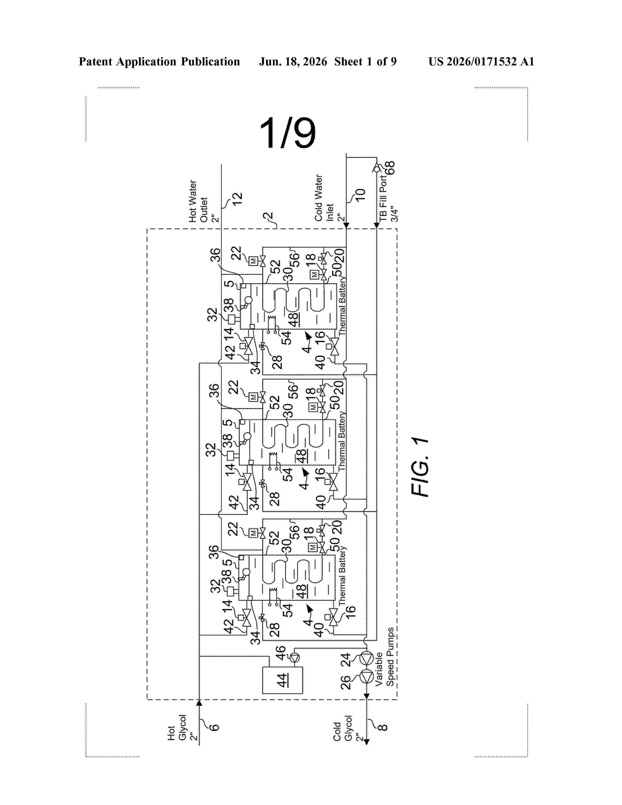
Resumen de: US20260171532A1
0000 A method for controlling a heating system to meet a heating demand, the heating system including more than one thermal battery, the method including comparing a state of charge (SOC) of one of the more than one thermal battery to a low thermal storage threshold, wherein if the SOC is lower than the low thermal storage threshold and the more than one thermal battery is more than one thermal battery, disposing the control valve of the one of the more than one thermal battery in a closed state; and comparing the SOC of one of the more than one thermal battery to a high thermal storage threshold, wherein if the SOC is greater than the high thermal storage threshold, disposing the control valve of the one of the more than one thermal battery in an open state.
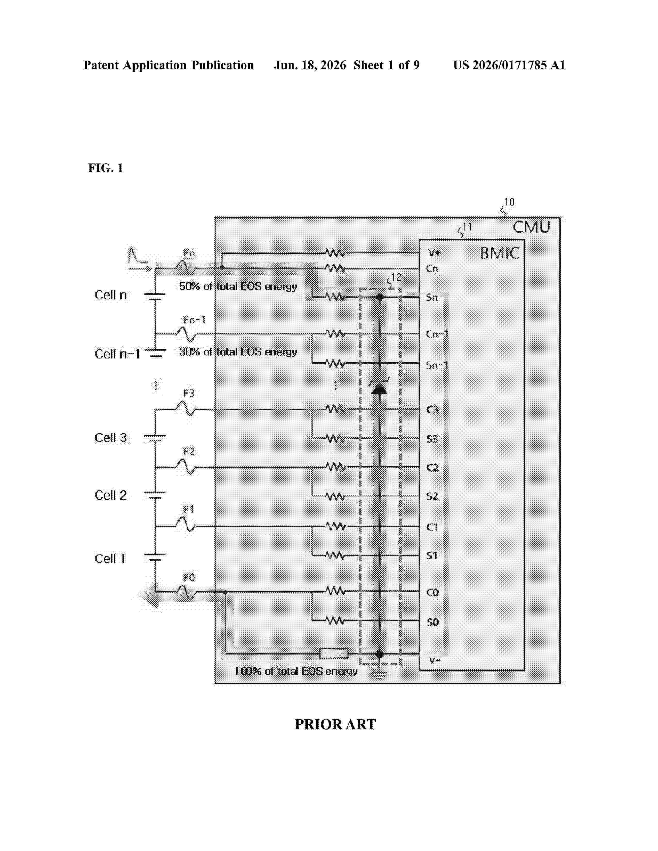
Resumen de: US20260171785A1
An adaptive battery cell monitoring device includes a cell monitoring circuit configured to monitor n battery cells (where n is a natural number) included in a battery module. The device further includes an electrical overstress (EOS) protection circuit configured to protect the cell monitoring circuit from external EOS. The EOS protection circuit is connected between an uppermost terminal of the cell monitoring circuit and a ground terminal of the cell monitoring circuit. The uppermost terminal of the cell monitoring circuit is connected to a positive electrode of an uppermost battery cell of the battery module including k battery cells (where k is a natural number equal to or less than n). The ground terminal of the cell monitoring circuit is connected to a negative electrode of a bottommost battery cell of the battery module. The device further includes a first bypass circuit configured to bypass the external EOS.
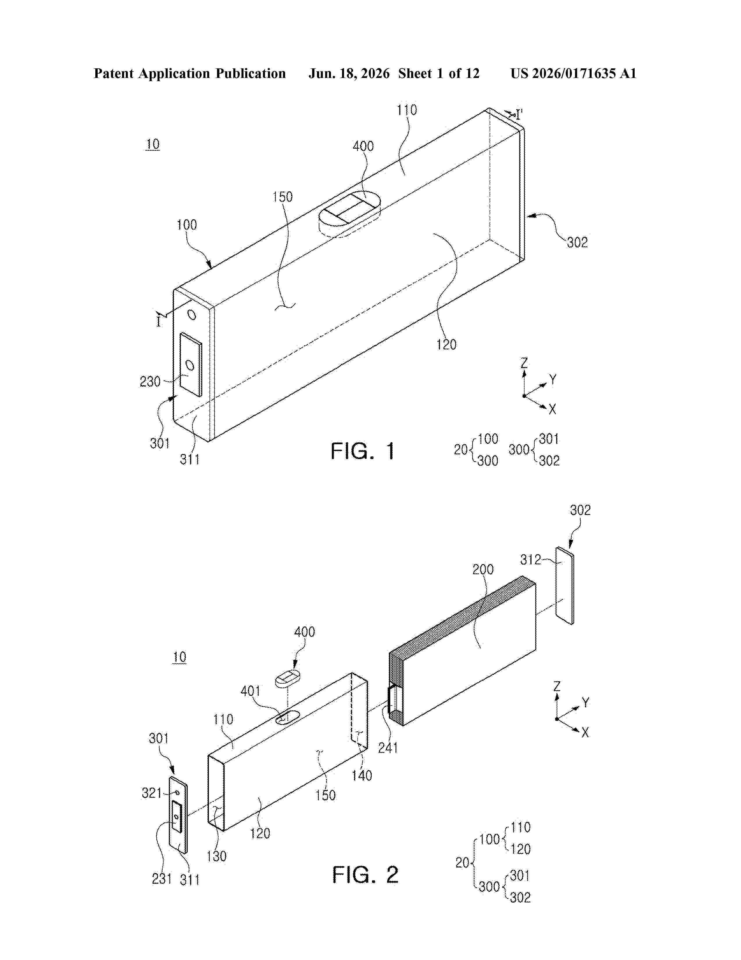
Resumen de: US20260171635A1
A battery cell comprises a cell housing having an accommodation portion accommodating an electrode assembly, a vent hole provided in a portion of the cell housing to communicate externally, and a venting device sealing the vent hole, wherein the venting device comprises a first venting portion communicating with the accommodation portion, a second venting portion spaced apart from the first venting portion and communicating externally, a side surface portion in which both open ends are connected to the first venting portion and the second venting portion to form a filtration space, and a filter portion disposed in the filtration space to filter gas.
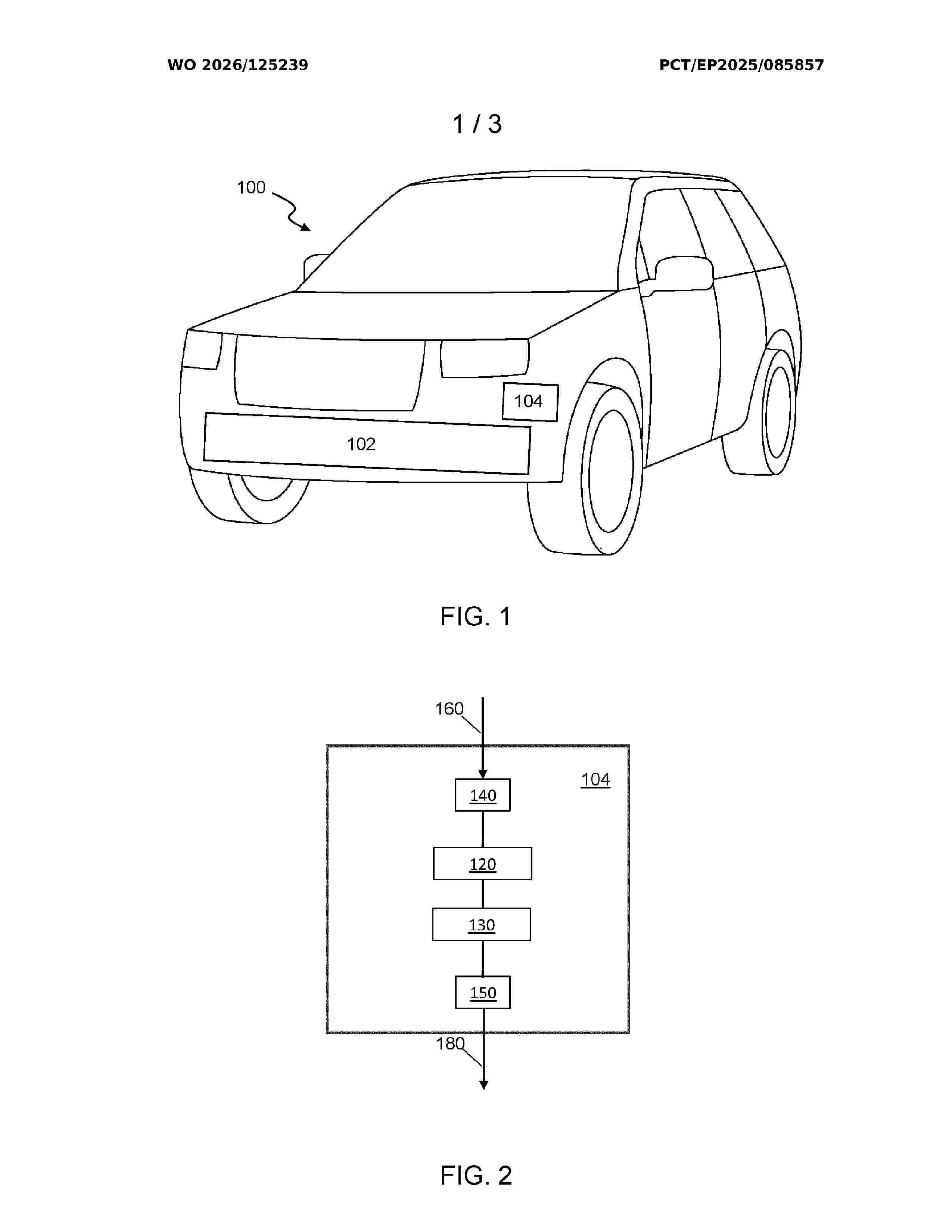
Resumen de: WO2026125239A1
Aspects of the present invention relate to a battery management system (104) for a battery (102) in an electric, or hybrid-electric vehicle (100), the vehicle having a first electrical circuit (310) that connects the battery to an electric drive unit, EDU, (312) of the vehicle, and a second electrical circuit (302) that connects a second load (304) to the battery. The battery management system is configured: in response to a first operational condition of the vehicle, to send a first control message to a first actuator (308) used to open the first electrical circuit and disconnect it from the battery, the control message comprising a first instruction to set a response time of the first actuator.
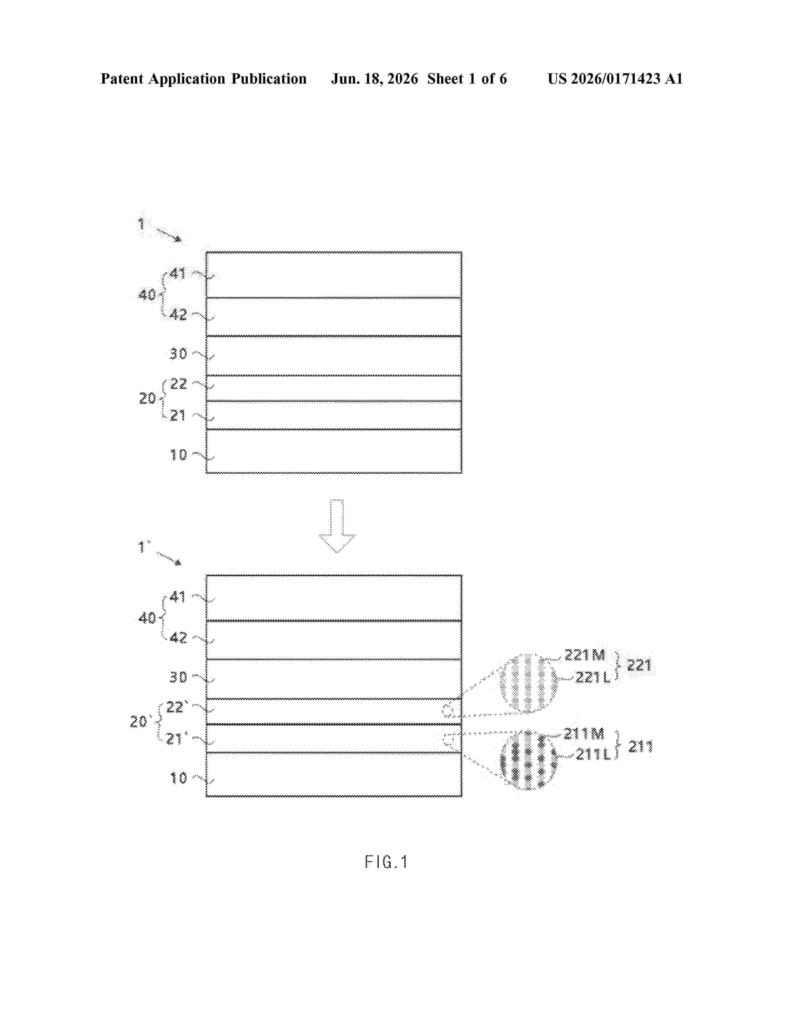
Resumen de: US20260171423A1
0000 An anodeless all solid state battery includes an anode current collector, a first intermediate layer disposed on the anode current collector and including a first metal for forming a solid solution alloy with lithium, a second intermediate layer disposed on the first intermediate layer and including a second metal for forming an intermetallic alloy with lithium, a solid electrolyte layer disposed on the second intermediate layer, a cathode active material layer disposed on the solid electrolyte layer, and a cathode current collector disposed on the cathode active material layer.
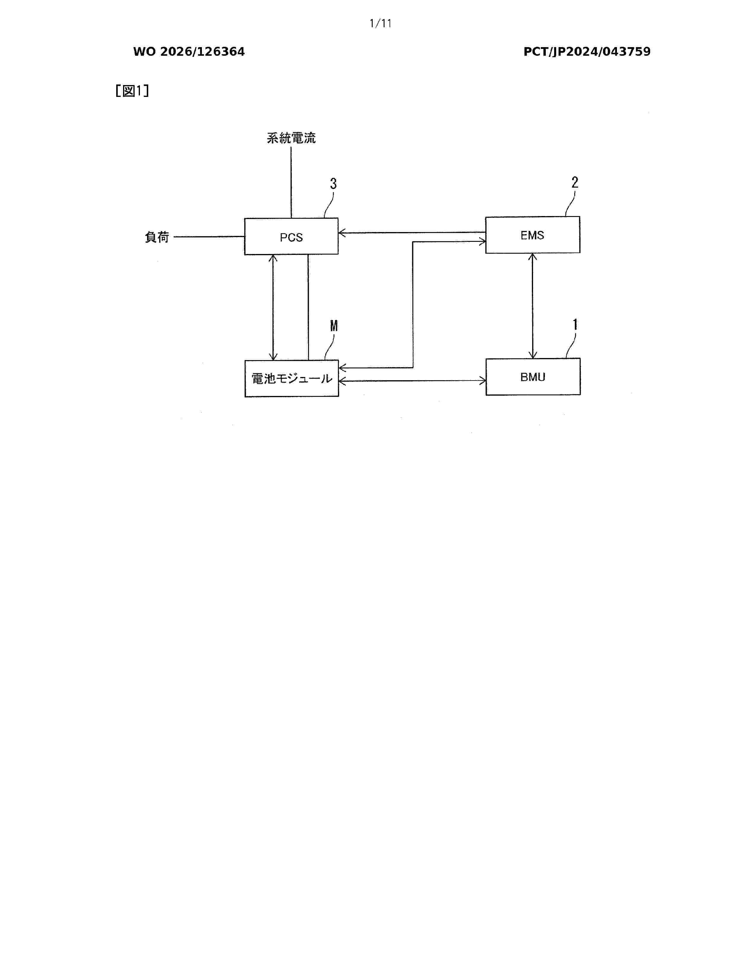
Resumen de: WO2026126364A1
Provided is a battery management system in which functions assigned to a lower-level unit that controls a battery module and a higher-level unit that supervises the lower-level unit are optimized, with consideration given to reuse after mounting on a vehicle. The battery management system comprises: a lower-level unit (CMU) that is associated with each battery module (M) having a plurality of battery cells (C), and controls the battery module (M); and a higher-level unit (BMU) that supervises a plurality of lower-level units (CMU). Each lower-level unit (CMU) determines a state estimation value indicating a state of each battery cell (C), and transmits the state estimation value to the higher-level unit (BMU). The higher-level unit (BMU), on the basis of the respective state estimation values transmitted and received from the plurality of lower-level units (CMU), determines a total state estimation value of an entire pack (P) composed of the plurality of battery modules (M).
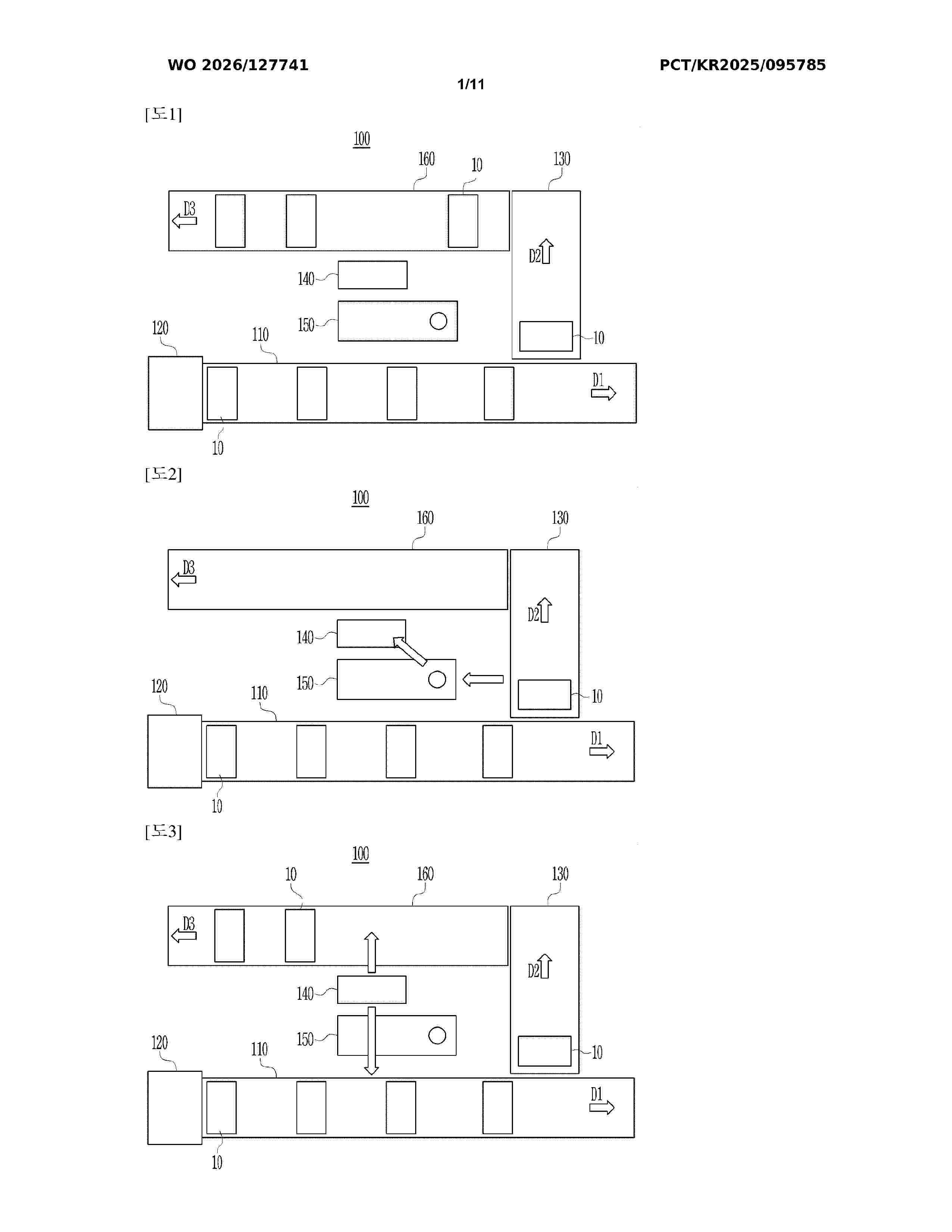
Resumen de: WO2026127741A1
A battery cell inspection device according to an embodiment of the present invention may comprise: a first transfer unit for transferring a battery cell; a vision inspection unit for acquiring appearance information of the battery cell; a second transfer unit for transferring the battery cell that has been determined to be abnormal from the appearance information acquired from the vision inspection unit; a pickup unit for moving the battery cell transferred by the second transfer unit; and a plasma inspection unit for using a plasma arc to inspect whether the surface of the battery cell transferred by the pickup unit has defects.
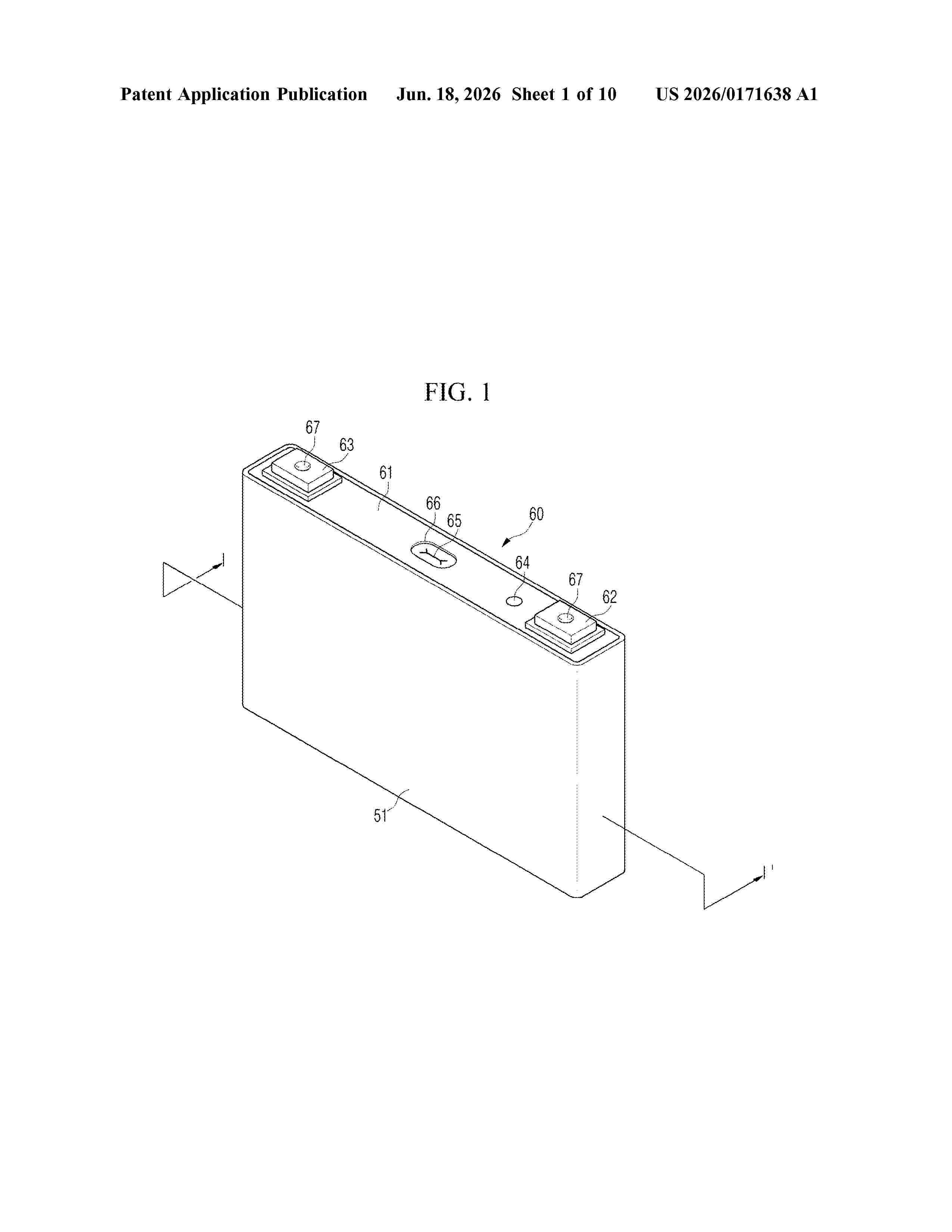
Resumen de: US20260171638A1
The present disclosure relates to a secondary battery including an insulating member. The secondary battery includes an electrode assembly, a case in which the electrode assembly is accommodated, a cap plate comprising a terminal electrically connected to the electrode assembly and bonded to the case, and an insulating member interposed between the electrode assembly and the cap plate in the case, wherein the insulating member includes a first body and a second body located adjacent to one another in a longitudinal direction, and a connection body located between the first body and the second body and comprising a first groove into which at least a portion of the first body is inserted and a second groove into which at least a portion of the second body is inserted.
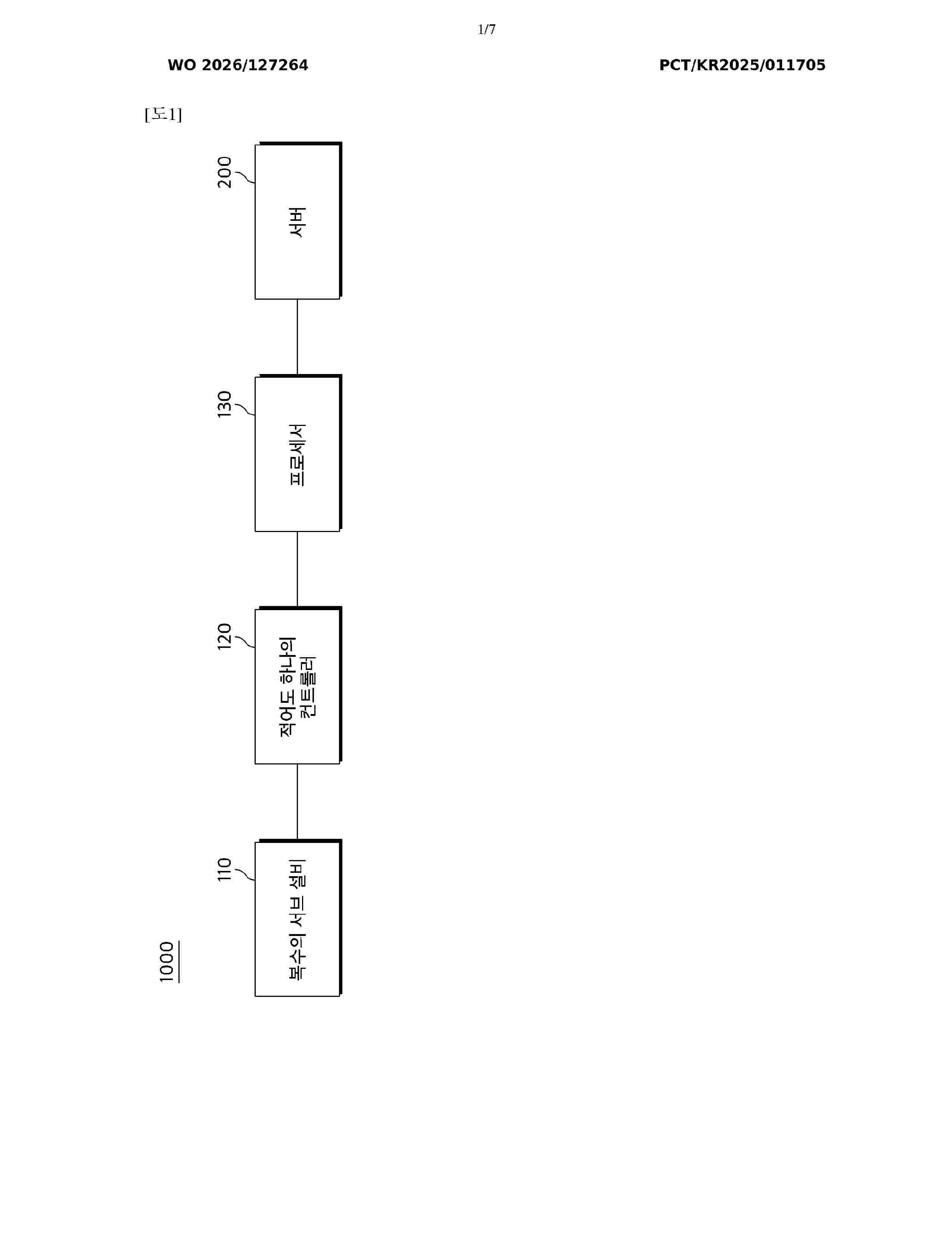
Resumen de: WO2026127264A1
According to an embodiment disclosed herein, a manufacturing process management method comprises, in a secondary battery manufacturing process, a step of identifying a current collector ID on the basis of an identification means corresponding to the current collector of a semi-finished cell, a step of checking information related to the process of manufacturing the semi-finished product cell, and a step of matching the information related to the manufacturing process to the current collector ID.
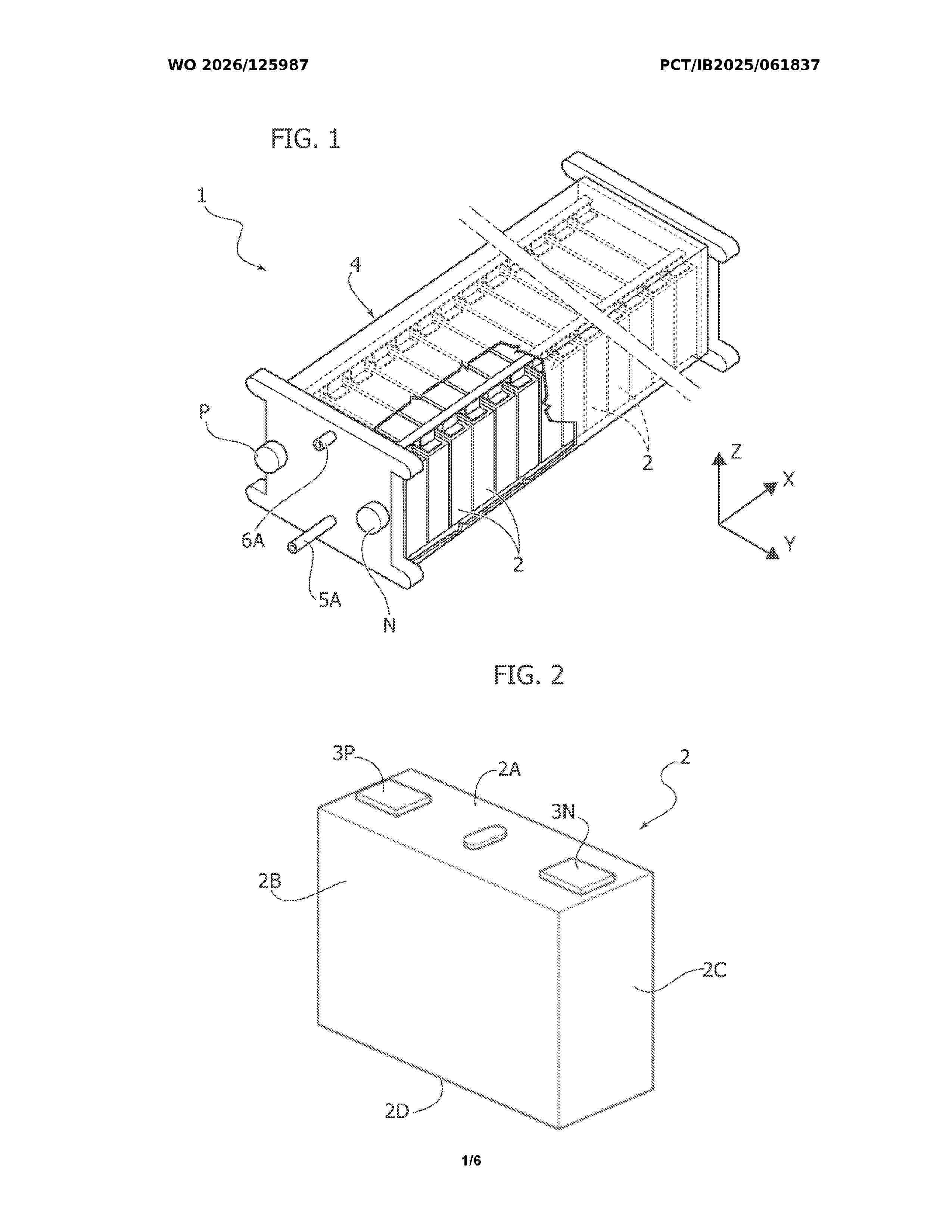
Resumen de: WO2026125987A1
An electric battery unit, for example a battery pack or a single module contained within a battery pack, comprises a housing (4) and a plurality of battery cells (2) within the housing (4), which are configured and arranged to come into direct contact with a flow of a temperature-regulating liquid that passes through the housing (4) for maintaining the battery cells (2) within a determined temperature range. The temperature-regulating liquid flows from an inlet collector chamber (5), which extends below the battery cells (2), through the spaces (7) between the battery cells (2) and up to an outlet collector chamber (6) which extends above the battery cells (2). The inlet collector chamber (5) communicates with the spaces (7) between the battery cells via a plurality of relatively restricted passages (9), which offer the flow of the temperature-regulating liquid sufficient resistance to prevent the temperature-regulating liquid from tending to flow to a greater extent in the spaces that are closer to the inlet and/or the outlet for the temperature-regulating liquid. The restricted passages are apertures (9) formed in a wall (50A) on which the battery cells (2) are supported. This wall (50A) has further apertures for the communication of the inlet collector chamber (5) with tubular columns (51) that rise vertically from the wall (50A), at least in some of the spaces (7) between the cells. The tubular columns (51) each have at least one outlet aperture (52), which can function a
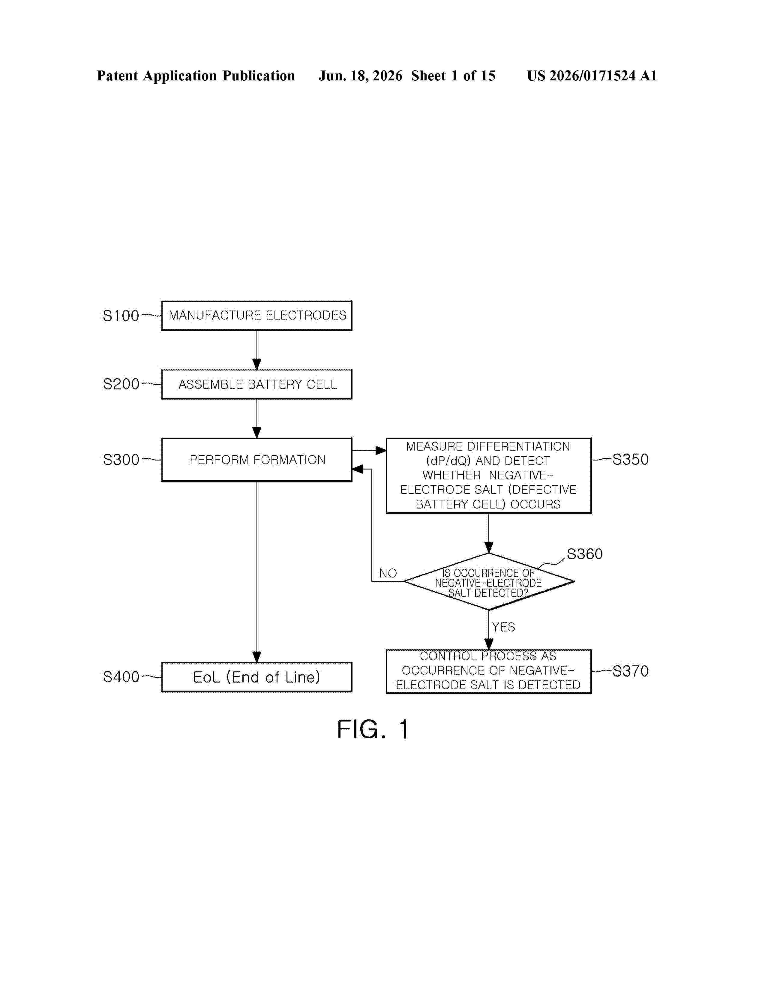
Resumen de: US20260171524A1
0000 A method for detecting a defect in a battery in a formation process is disclosed. In some implementations, the method includes: charging or discharging at least one battery cell in the formation process; measuring a pressure in the at least one battery cell or a differentiation (dP/dQ) of the pressure with respect to charge when the at least one battery cell is charged or discharged; and generating data on whether the at least one battery cell has a defect based on the differentiation (dP/dQ).
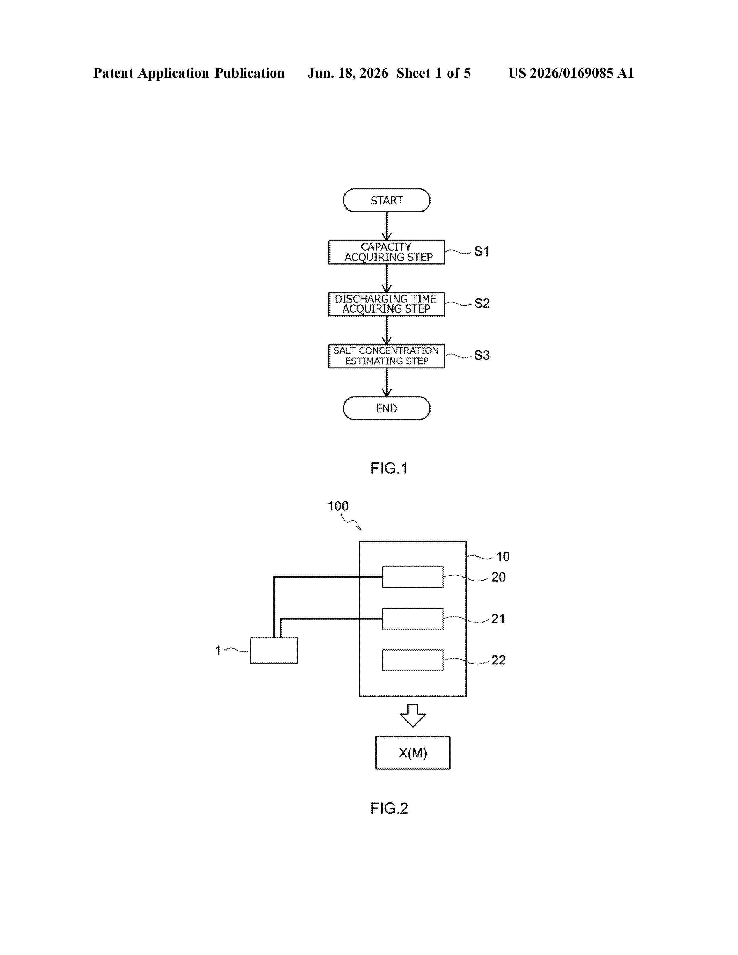
Resumen de: US20260169085A1
A method of estimating a salt concentration in an electrolyte solution of a secondary battery includes: a capacity acquiring step S1 of acquiring a capacity of a secondary battery that is to be an estimation object; a discharging time acquiring step S2 of acquiring a discharging time when the secondary battery is discharged under a predetermined condition; and a salt concentration estimating step S3 of estimating the salt concentration in the electrolyte solution of the secondary battery based on the acquired capacity of the secondary battery, the acquired discharging time, and a table recording a relationship between the capacity, the discharging time, and the salt concentration in the electrolyte solution of the secondary battery, related to the secondary battery that is to be the estimation object.
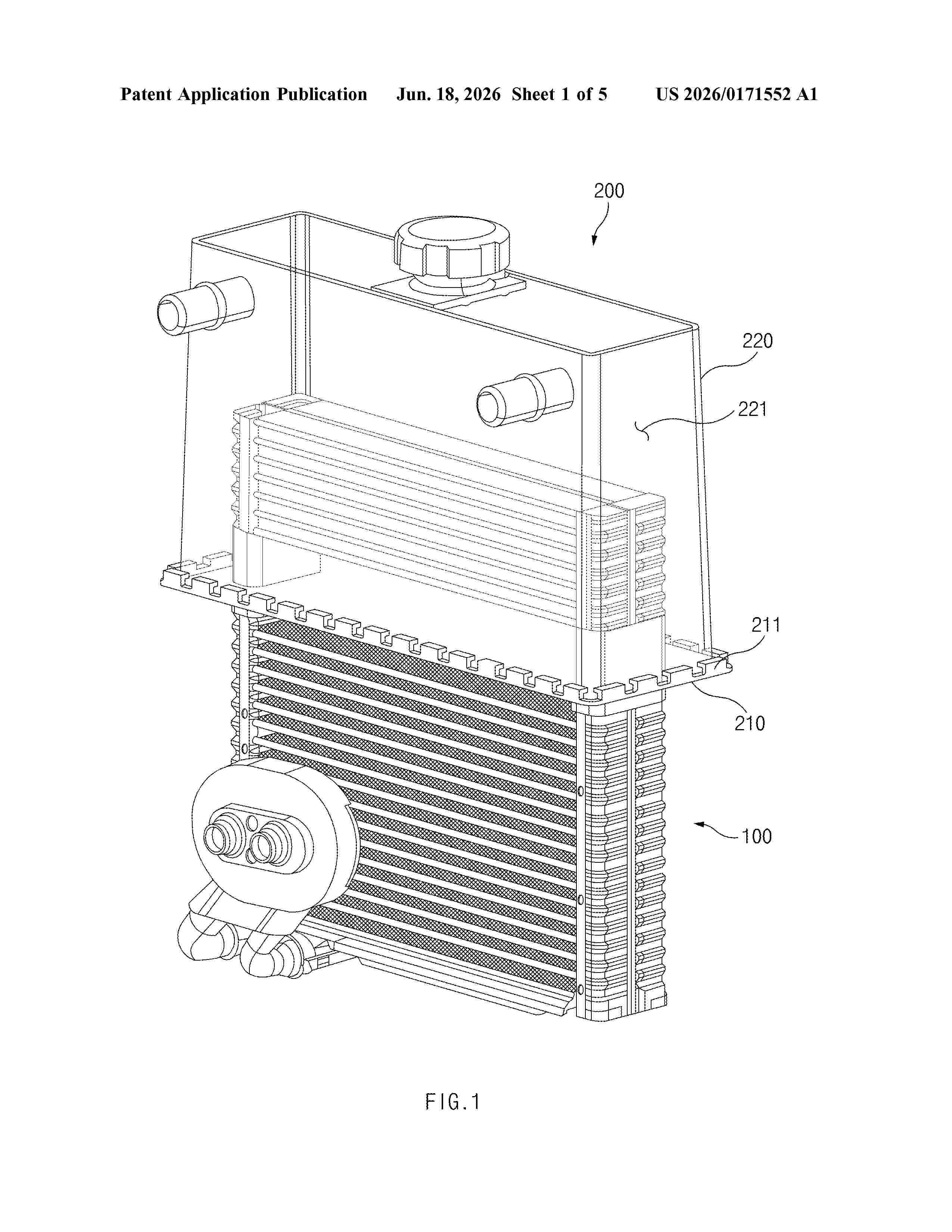
Resumen de: US20260171552A1
A battery cooling circuit is provided. The battery cooling circuit is configured to cool a battery provided in a vehicle by using an air conditioner system in the vehicle. The battery cooling circuit includes an air-cooled part connected in series to the air conditioner system and configured to cool a refrigerant by allowing the refrigerant to exchange heat with a first cooling fluid in the air conditioner system while flowing. The battery cooling circuit further includes a water-cooled part connected in series to a circuit configured to cool the battery. The water-cooled part is installed to communicate with the air-cooled part to allow the refrigerant to flow therein, configured to be filled with a second cooling fluid in the circuit configured to cool the battery, and configured to cool the second cooling fluid by allowing the second cooling fluid to exchange heat with the refrigerant.
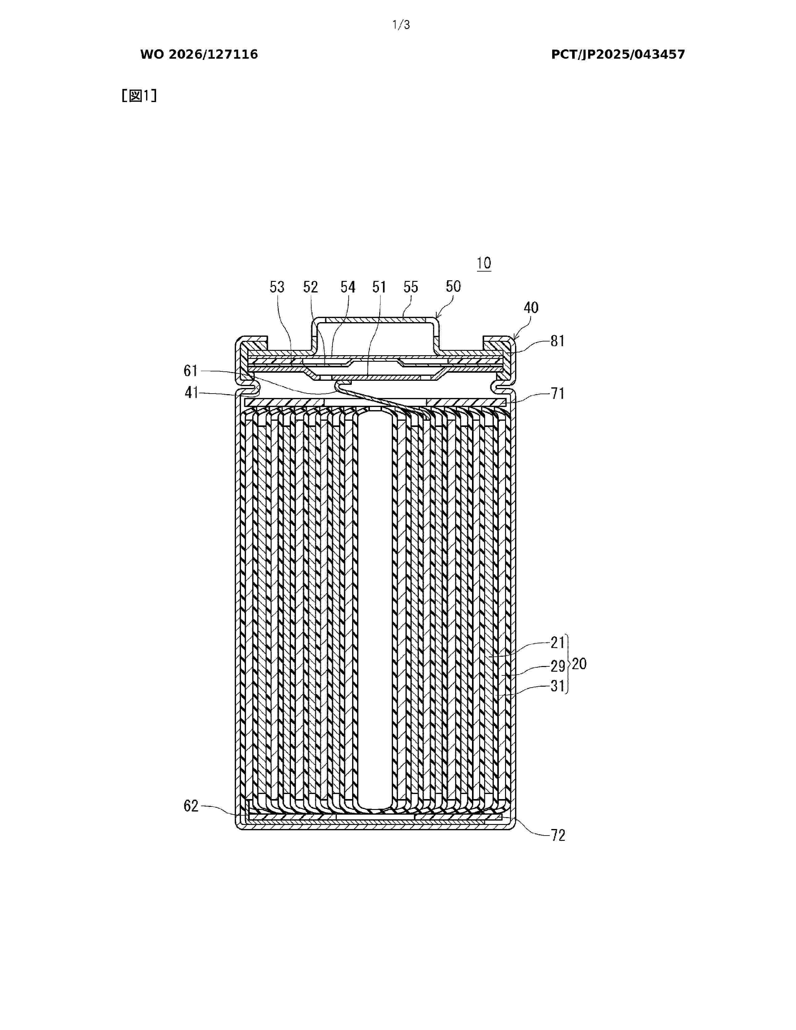
Resumen de: WO2026127116A1
This power storage device comprises an electrode body in which a first electrode plate and a second electrode plate are wound with a separator interposed therebetween, an electrolyte, a bottomed cylindrical case, and a sealing body. The first electrode plate is provided with a current collector having a first main surface and a second main surface, and a first active material layer provided on the first main surface. The first active material layer includes a first region extending from one width-direction end of the current collector to an intermediate point, and a first main region extending from the intermediate point to the other width-direction end. The mass per unit volume of the first active material layer in the first region is at least 50% and less than 100% of the mass per unit volume of the first active material layer in the first main region, and the proportion of the first region in the first active material layer is 50% or less. The electrode body is accommodated inside the case such that the the first region faces the sealing-body side and the first main region faces the bottom-part side of the case.
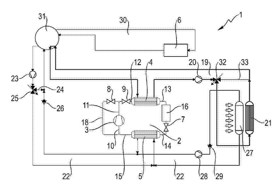
Resumen de: DE102024138370A1
Die Erfindung betrifft einen Kühlmittelkreislauf (1), insbesondere für ein Kraftfahrzeug, mit einem Kältemittelkreislauf (2) mit einem Verdichter (3), einem ersten Wärmeübertrager (4) und einem zweiten Wärmeübertrager (5), und mit zumindest zwei Expansionsventilen (7, 8), wobei der erste Wärmeübertrager (4) mit einem ersten Fluidkreislauf (19) fluidverbunden ist, wobei der erste Fluidkreislauf (19) weiterhin eine Pumpe (20) und einen Heizkörper (21) aufweist, wobei der zweite Wärmeübertrager (5) mit einem zweiten Fluidkreislauf (22) fluidverbunden ist, wobei der zweite Fluidkreislauf (22) eine Pumpe (23) aufweist und wobei ein dritter Fluidkreislauf (30) vorgesehen ist, in welchem zumindest ein zu temperierendes Aggregat (6) vorgesehen ist, wobei eine Ventileinrichtung (31) vorgesehen ist, welche die Durchströmung und/oder Fluidverbindung des ersten Fluidkreislaufs (19), des zweiten Fluidkreislaufs (22) und/oder des dritten Fluidkreislaufs (30) bewirkt und/oder steuert.
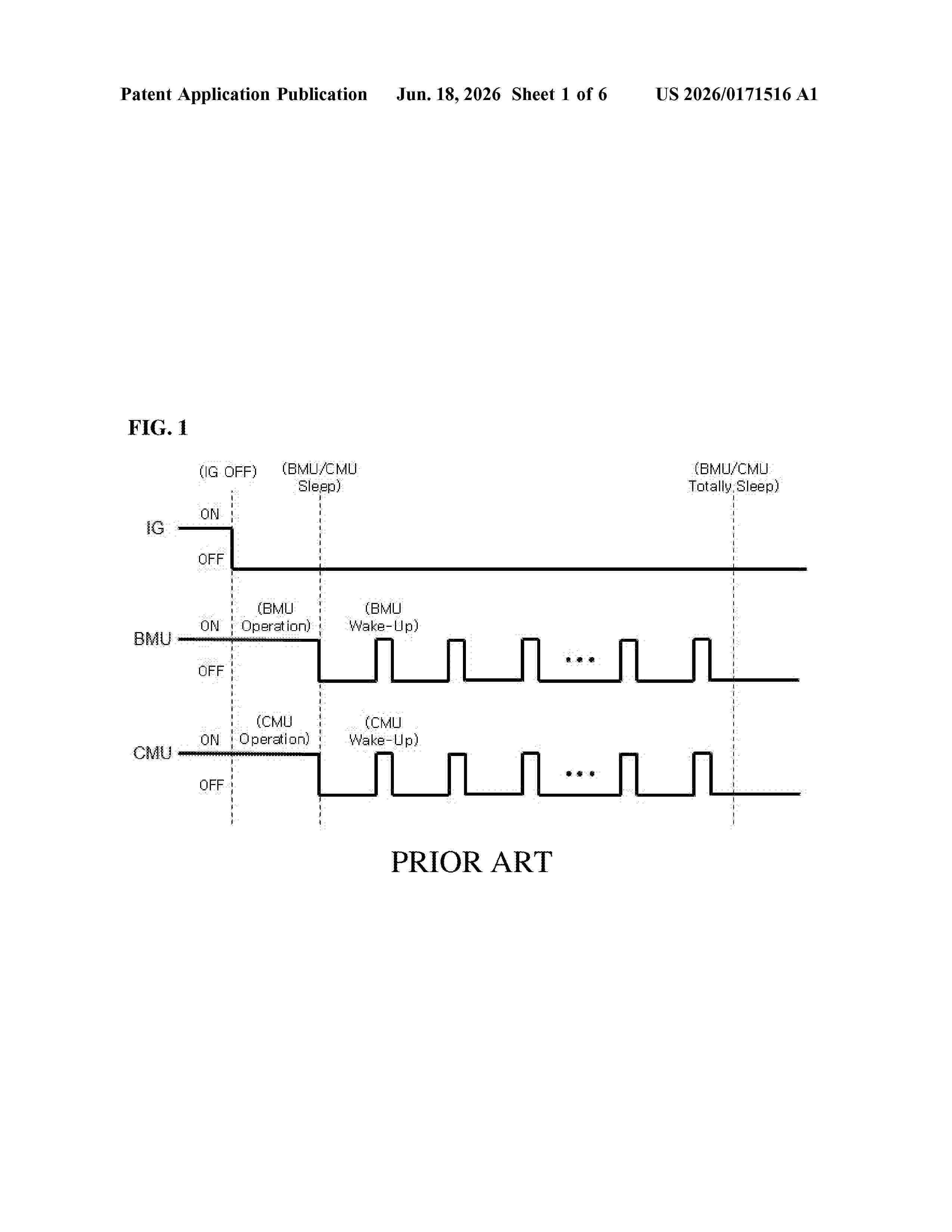
Resumen de: US20260171516A1
A battery management system with a continuous battery cell monitoring function includes a cell monitoring unit (CMU) configured to continuously monitor a status of a plurality of battery cells included in a battery module. The CMU is further configured to, upon detecting an abnormal state of at least one battery cell, notify a battery management unit (BMU) of the abnormal state of the at least one battery cell. The system further includes the BMU configured to manage the at least one CMU. The BMU is further configured to, upon receiving notification of the abnormal state of the at least one battery cell from the CMU, transition from a sleep mode to an active mode and respond to the abnormal state of the at least one battery cell.
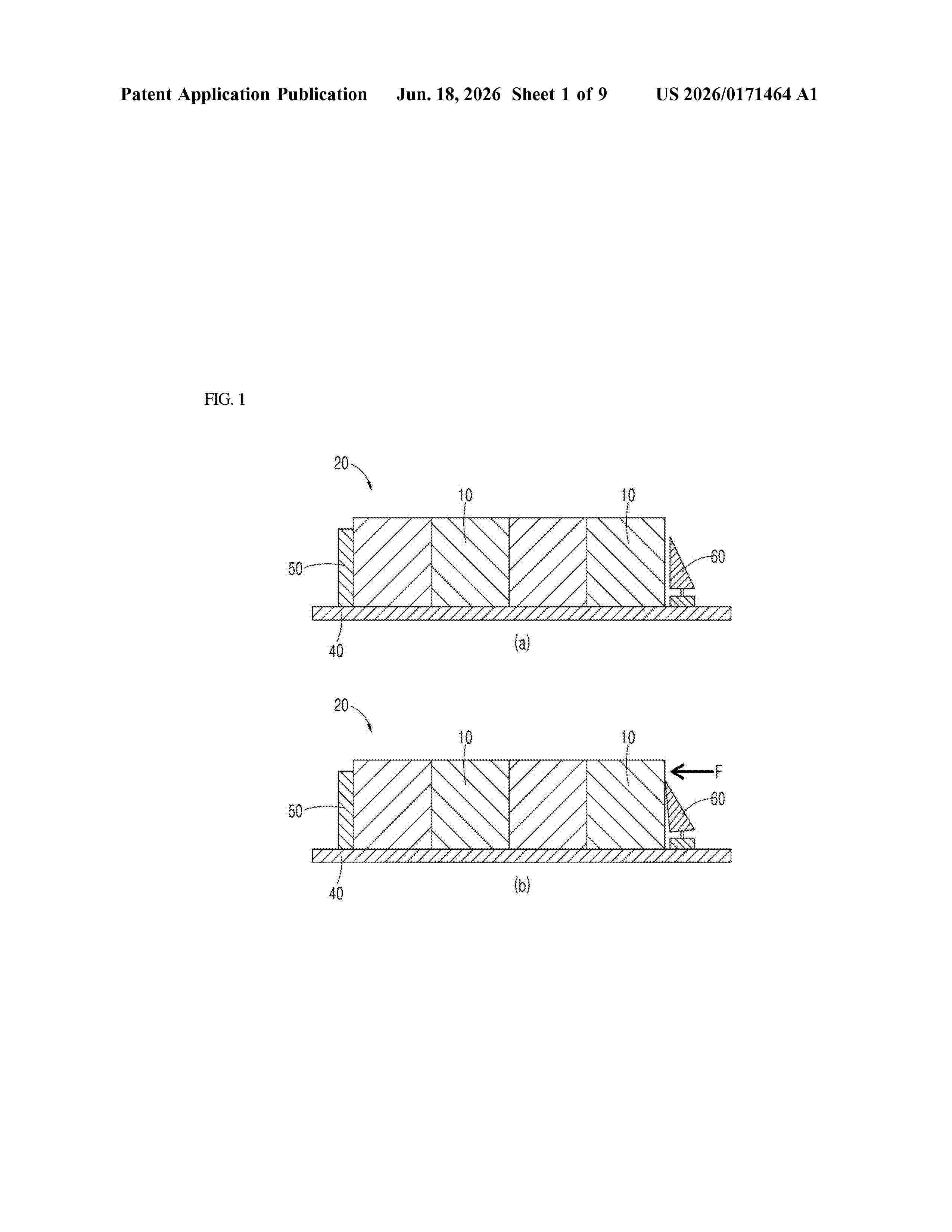
Resumen de: US20260171464A1
A battery pack system includes a plurality of battery modules with stacked battery cells. The plurality of battery modules is secured to multiple seating portions in a battery housing. The housing includes a base plate forming its bottom surface, from which multiple transverse members protrude upward, running parallel to each other. A set of longitudinal members intersects these transverse members, creating defined seating portions. Two end-plates are connected to the transverse members, forming parallel side walls. The distance between the end-plates'facing pressing surfaces is precisely adjusted and fixed.
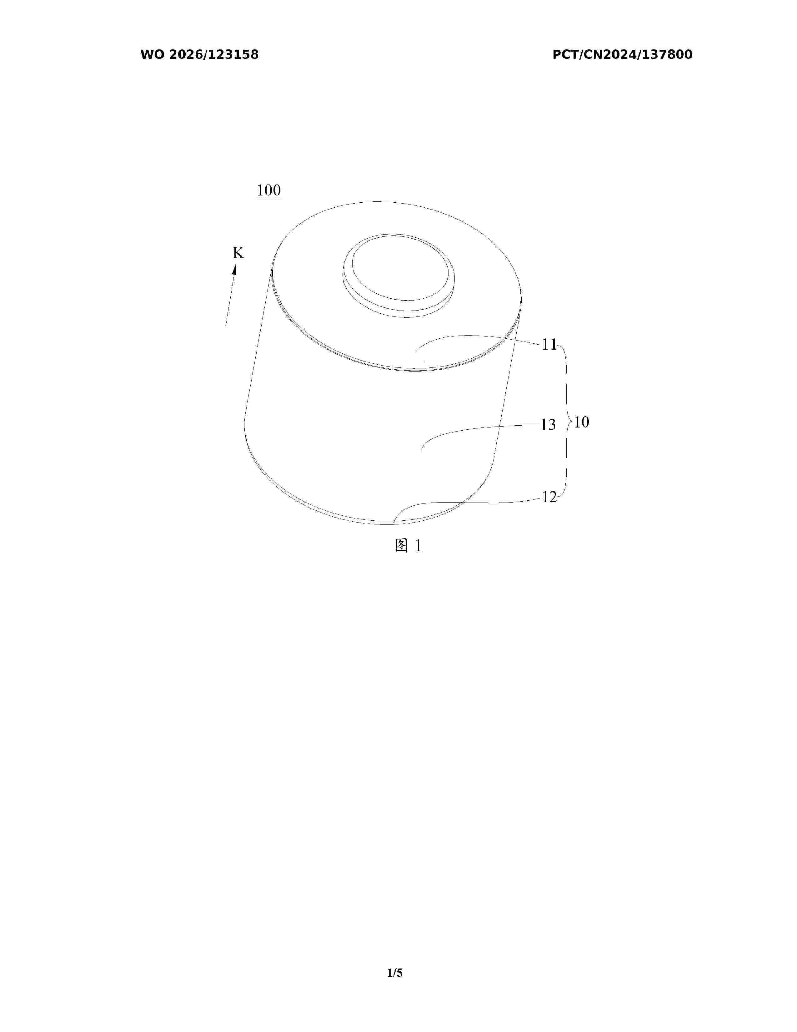
Resumen de: WO2026123158A1
A secondary battery and an electronic device. The secondary battery comprises an electrode assembly, wherein the electrode assembly comprises a first electrode sheet, a separator, and a second electrode sheet that are stacked and wound. In a winding direction, the first electrode sheet comprises a first starting end. In the thickness direction of the first electrode sheet, the second electrode sheet is an electrode sheet adjacent to the first starting end. The secondary battery further comprises a first adhesive layer. In the thickness direction of the first electrode sheet, the first adhesive layer is disposed on the separator between the first starting end and the second electrode sheet, and the first adhesive layer covers the first starting end. In a direction opposite to the winding direction, the first adhesive layer extends beyond the first electrode sheet from the first starting end. The risk of burrs at the first starting end piercing the separator can be reduced, and exposure of the first starting end caused by slipping of the first starting end can be reduced, thereby reducing the occurrence of short circuits caused by the burrs at the first starting end piercing the separator, and improving the safety performance of the secondary battery.
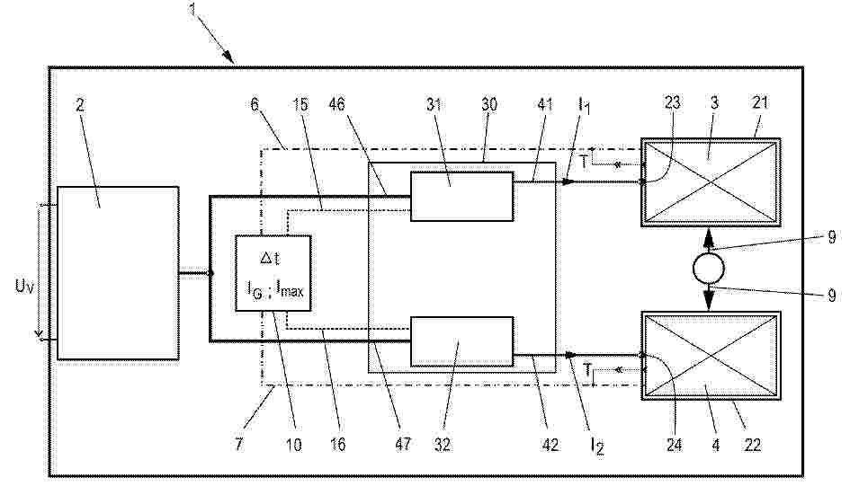
Resumen de: DE102024138392A1
Die Erfindung betrifft ein Verfahren zum Laden eines ersten Akkupacks (3, 4) und eines zweiten Akkupacks (4, 3) mit einem Ladegerät (1), wobei das Ladegerät (1) eine erste Schnittstelle (23), eine zweite Schnittstelle (24), zumindest eine Leistungselektronik (30) sowie eine Steuerung (10) umfasst. Die Steuerung (10) erfasst, wenn zu einem ersten Zeitpunkt (tA) der erste Akkupack (3, 4) mit der ersten Schnittstelle (23, 24) verbunden wird sowie zu einem zweiten Zeitpunkt (tB) der zweite Akkupack (4, 3) mit der zweiten Schnittstelle (24, 23) verbunden wird. Die Steuerung (10) steuert die Leistungselektronik (30) in Abhängigkeit der erfassten Zeitpunkte (tA, tB) und einer vorgegebenen Zeitspanne (Δt) derart, dass die Ladeleistung auf der ersten Schnittstelle (23, 24) zum Laden des ersten Akkupacks (3, 4) und/oder auf der zweiten Schnittstelle (24, 23) zum Laden des zweiten Akkupacks (4, 3) ausgegeben wird, wobei primär der erste Akkupack (3, 4) geladen wird, wenn der erste Zeitpunkt (tA) um mehr als die vorgegebene Zeitspanne (Δt) vor dem zweiten Zeitpunkt (tB) liegt.
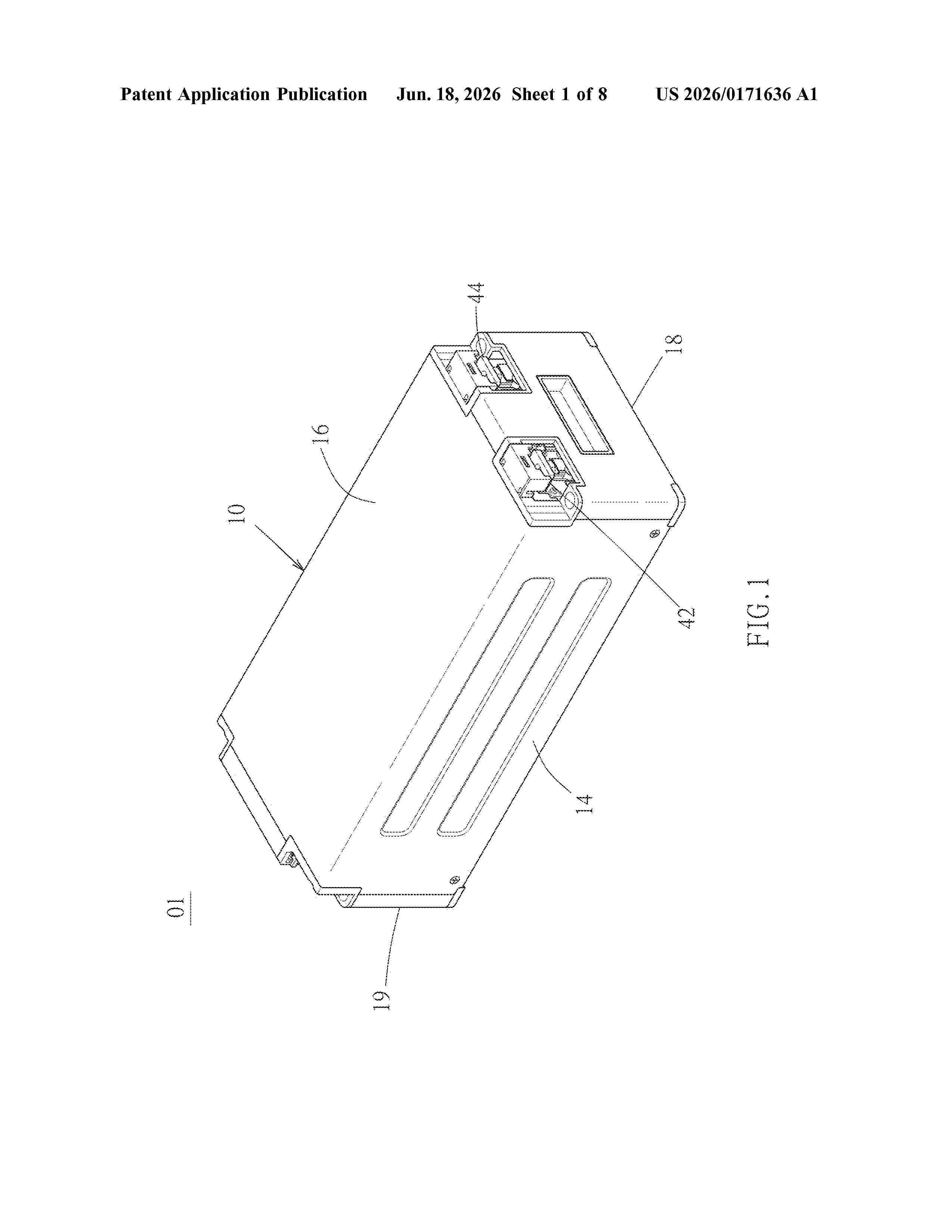
Resumen de: US20260171636A1
The present invention provides an overcurrent circuit breaker for a pouch cell battery, comprising a first electrical connection plate, a second electrical connection plate, a current-interrupting element, and a protective housing. The first electrical connection plate electrically connects a first busbar of the pouch cell battery, while the second electrical connection plate connects a first electrode. The current-interrupting element forms a current path between the joining plates and is positioned inside a protective housing made of a flame-retardant material with insulating and heat-insulating properties. The overcurrent circuit breaker, located inside the pouch cell battery, provides an active protection for the battery cell module by preventing excessive current during charging or discharging.
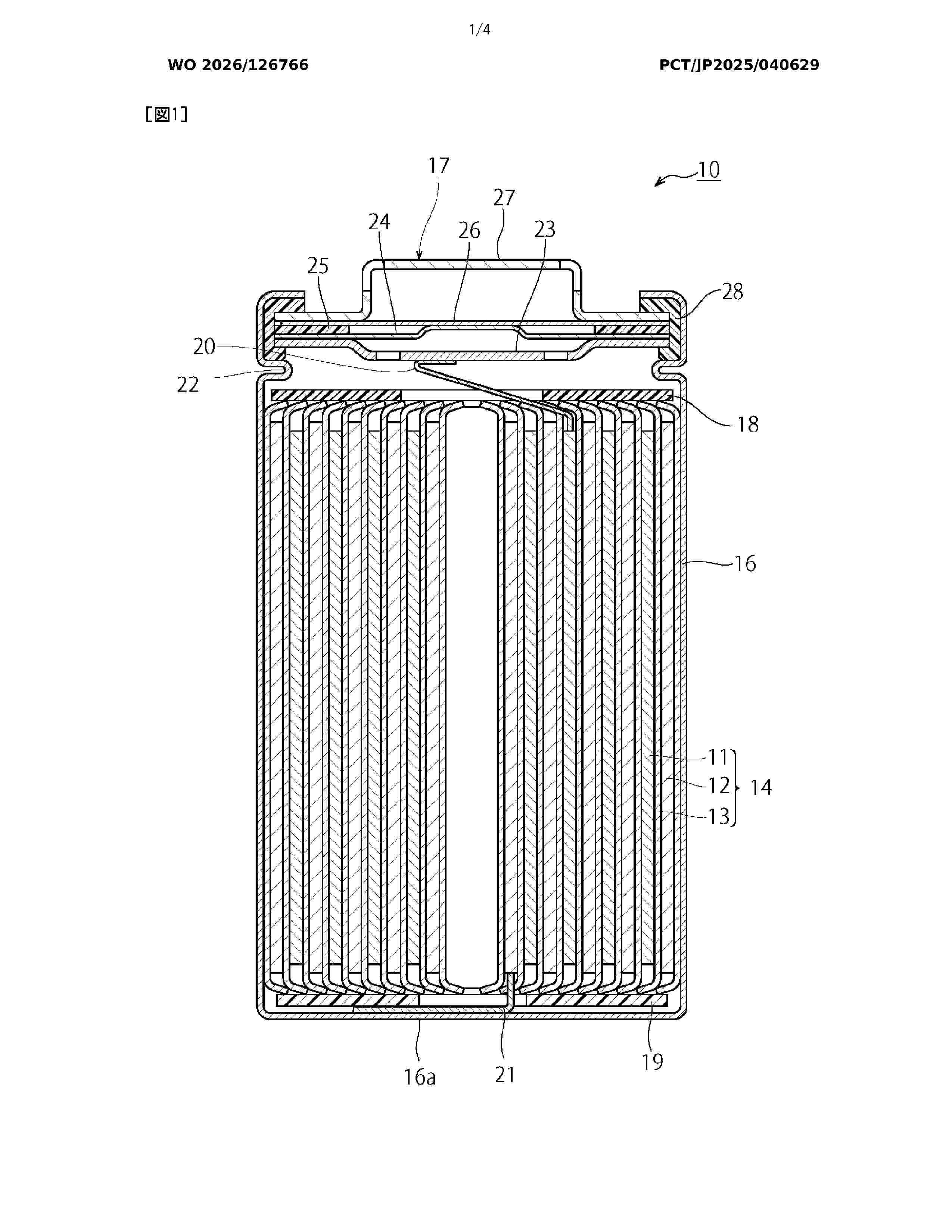
Resumen de: WO2026126766A1
This non-aqueous electrolyte secondary battery comprises: an electrode body (14) in which a positive electrode (11) and a negative electrode (12) are wound with a separator (13) interposed therebetween; and a bottomed cylindrical exterior can for accommodating the electrode body (14). The positive electrode (11) has a starting end part (50) on the winding outer side of the negative electrode (12). The negative electrode (12) has a negative electrode lead (21) of which one end is joined to the starting-end-part (70) side of the negative electrode (12) and of which the other end is joined to the exterior can. In the negative electrode (12), an adhesive tape (60) is affixed to the reverse surface of a position A facing the starting end part (50) of the positive electrode (11).
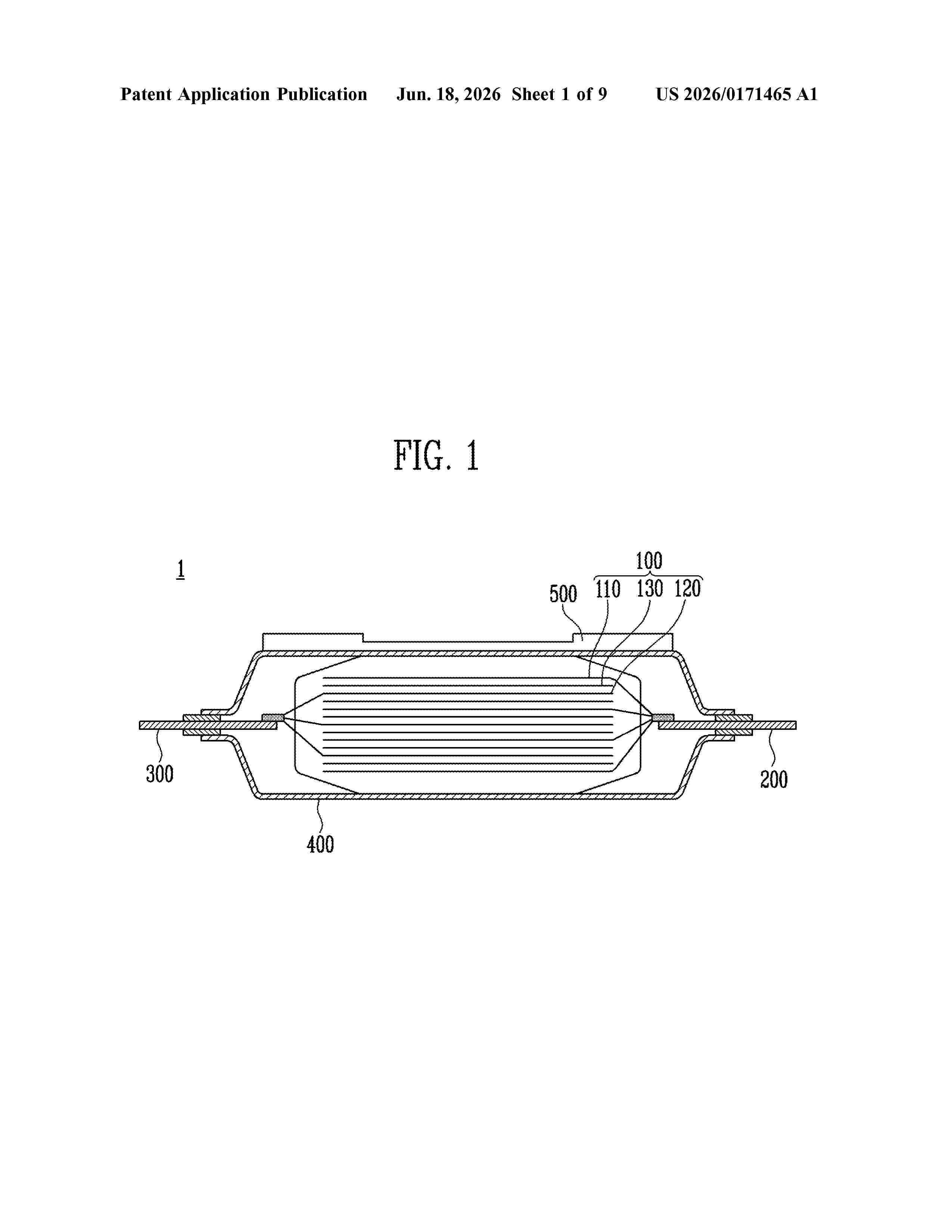
Nº publicación: US20260171465A1 18/06/2026
Solicitante:
SK ON CO LTD [KR]
SK On Co., Ltd.
Resumen de: US20260171465A1
0000 The present disclosure relates to a battery cell and a battery assembly including the same. The battery cell may include: an electrode assembly in which a plurality of positive electrodes and a plurality of negative electrodes are alternately stacked with a separator interposed therebetween along a predetermined direction; a positive electrode tab which is electrically connected to the plurality of positive electrodes at one end of a length direction perpendicular to the predetermined direction of the electrode assembly; a negative electrode tab which is electrically connected to the plurality of negative electrodes at the other end of the length direction of the electrode assembly; a pouch which accommodates the electrode assembly therein and exposes at least a portion of the positive electrode tab and at least a portion of the negative electrode tab to an outside; and a pressing pad coupled to one surface of the pouch.
 BOPI
BOPI
 Sede Electrónica