Si deseas distinguir tus productos, servicios o ambos de los de otra empresa, es posible que necesites una marca o nombre comercial. Descubre qué son, en qué consiste su procedimiento de registro y qué implica.

Información sobre los plazos de presentación de solicitudes de transformación de marcas de la Unión Europea en marca nacional española. Más información


Si tienes un nuevo dispositivo, producto o procedimiento que resuelva un problema técnico o tenga una ventaja práctica, existen distintas formas de protegerlo en España y en otros países. Descubre cómo hacerlo.

¿Tu innovación reside en la estética, la ornamentación o la apariencia de tu producto? Protégela mediante un diseño industrial. Descubre qué derechos confiere el registro y cómo realizar la tramitación.

Las indicaciones geográficas protegen el nombre de un producto originario de una zona geográfica, a la cual le debe una determinada calidad, reputación u otra característica. Descubre qué son, en qué consiste su procedimiento de registro y qué beneficios conceden.

Las patentes publicadas en todo el mundo son una valiosa fuente de información científica, técnica y comercial.

Si eres emprendedor/a o una empresa y quieres potenciar y mejorar la rentabilidad de tu negocio protegiendo de forma adecuada los activos intangibles de tu organización, en este espacio encontrarás lo necesario.


 1500
resultados
1500
resultados
 Última actualización
27/06/2026 [07:57:00]
Última actualización
27/06/2026 [07:57:00]


 Resultados 550 a 575 de 1500

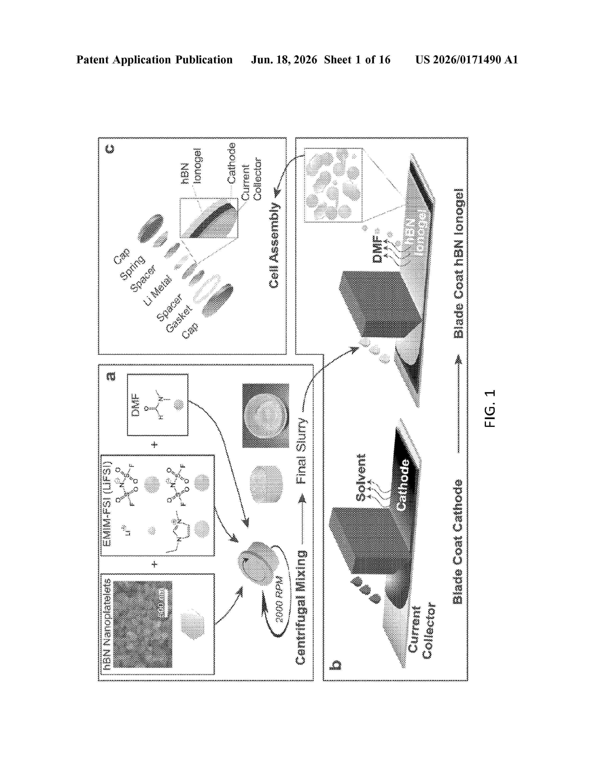
Resumen de: US20260171490A1
0000 An ionogel includes an ionic liquid electrolyte (ILE) comprising an ionic liquid (e.g., 1-ethyl-3-methyl-imidazolium bis(fluorosulfonyl)imide (EMIM-FSI)) and a lithium salt (e.g., lithium bis(fluorosulfonyl)imide (LiFSI)) dissolved in the ionic liquid; and a solid matrix material comprising hexagonal boron nitride (hBN) nanoplatelets mixed with the ionic liquid electrolyte in at least one solvent.

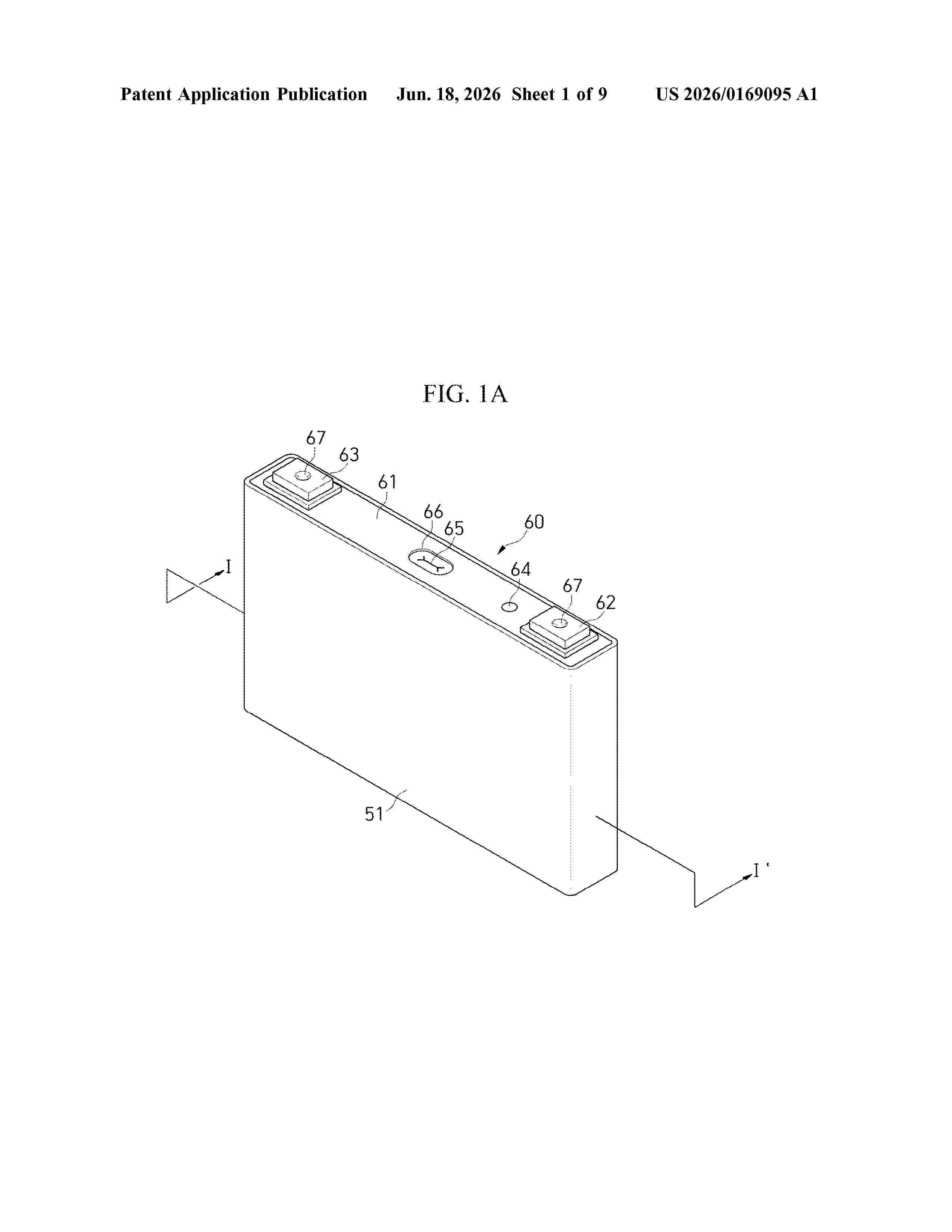
Resumen de: US20260169095A1
Disclosed herein are a method and system for detecting inter-cell short circuits in secondary batteries. The system includes a voltage measurement unit including a probe that comes into contact with a cell of a secondary battery to measure an inter-cell voltage, a short-circuit control unit configured to control an inter-cell short circuit, and an inter-cell short-circuit detection unit configured to measure a first voltage between a first cell and a second cell in the secondary battery, to create a short circuit between the first and second cells, to measure a second voltage between the first and second cells, to eliminate the short circuit between the first and second cells, to measure a third voltage between the first and second cells, and to determine whether a short circuit occurs between the first and second cells by using at least one of the first to third voltages.
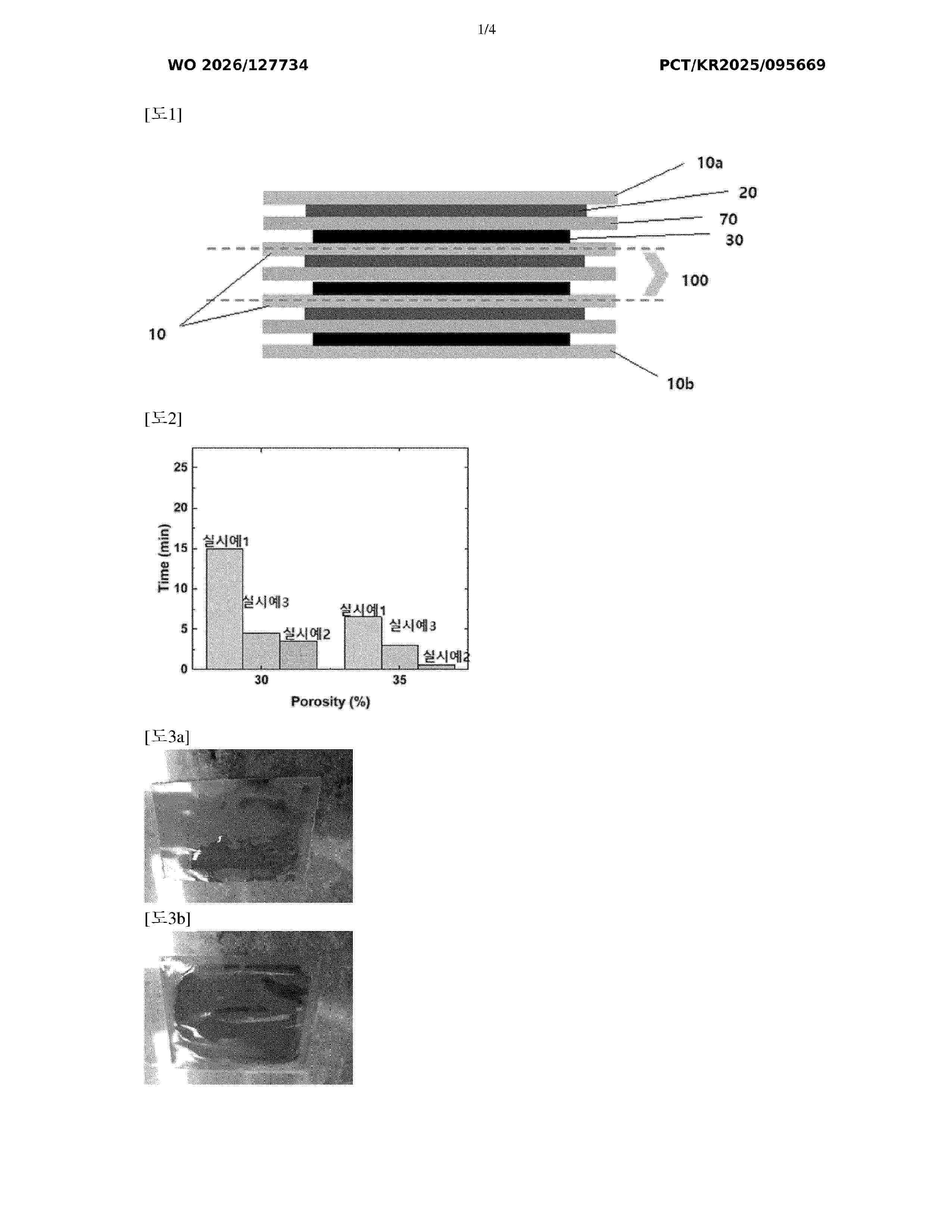
Resumen de: WO2026127734A1
The present invention relates to: a bipolar secondary battery in which volatilization and leakage of an electrolyte are suppressed, and which exhibits excellent conductivity, capacity, and cycle characteristics; and a method for manufacturing same. In the bipolar secondary battery, a plurality of bipolar electrodes each having a negative electrode active material layer and a positive electrode active material layer respectively formed on both surfaces of a metal current collector are stacked, the positive electrode active material layers and the negative electrode active material layers of adjacent bipolar electrodes face each other with a gel electrolyte layer disposed therebetween, and the gel electrolyte layer contains: a matrix including a cross-linked polymer of a polyfunctional (meth)acrylate-based compound; and a non-volatile electrolyte of a predetermined composition impregnated on the matrix.
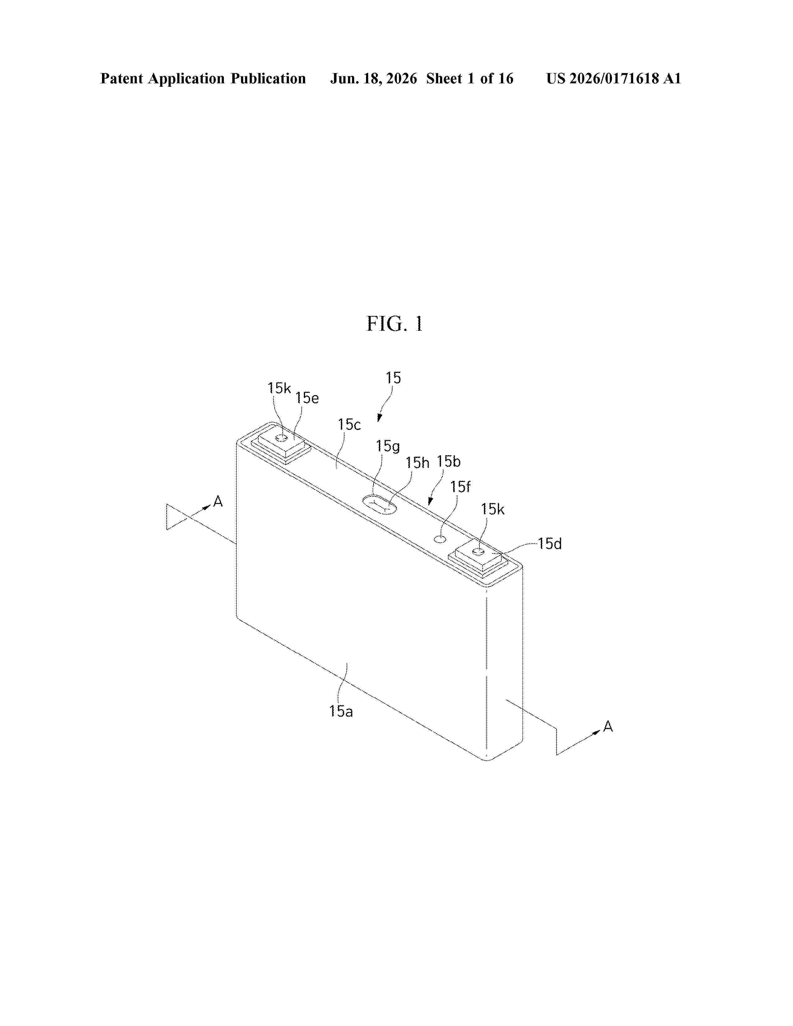
Resumen de: US20260171618A1
0000 The present disclosure provides a secondary battery module having a cell connection unit that maintains the connection between bus bars and circuit boards and battery cells, and thus a process of manufacturing the secondary battery module is simple, and problems such as electrical short and the like due to welding failure of bus bars do not occur, and an apparatus for manufacturing the same. The secondary battery module includes a module main body including a cell housing, which opens upwardly and provides an accommodation space, and a plurality of battery cells arranged in the cell housing, and a cell connection unit including a unit base coupled to an upper portion of the cell housing, a plurality of bus bars that are fitted to the unit base and connected to the battery cell, and circuit boards connected to the bus bars.
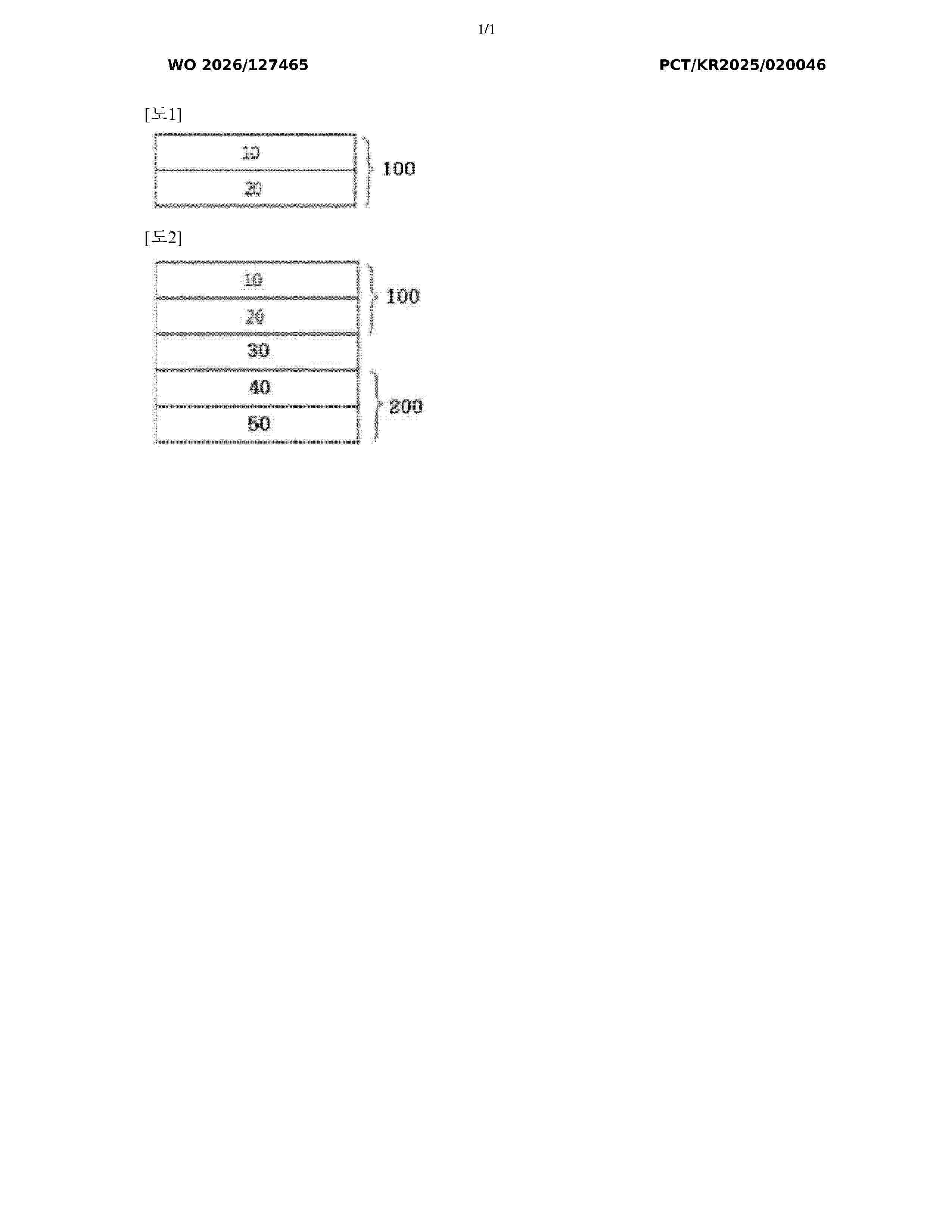
Resumen de: WO2026127465A1
The present invention relates to: an anode active material; a preparation method for the anode active material; an anode composition; an anode for a lithium secondary battery, comprising same; and a lithium secondary battery comprising the anode.
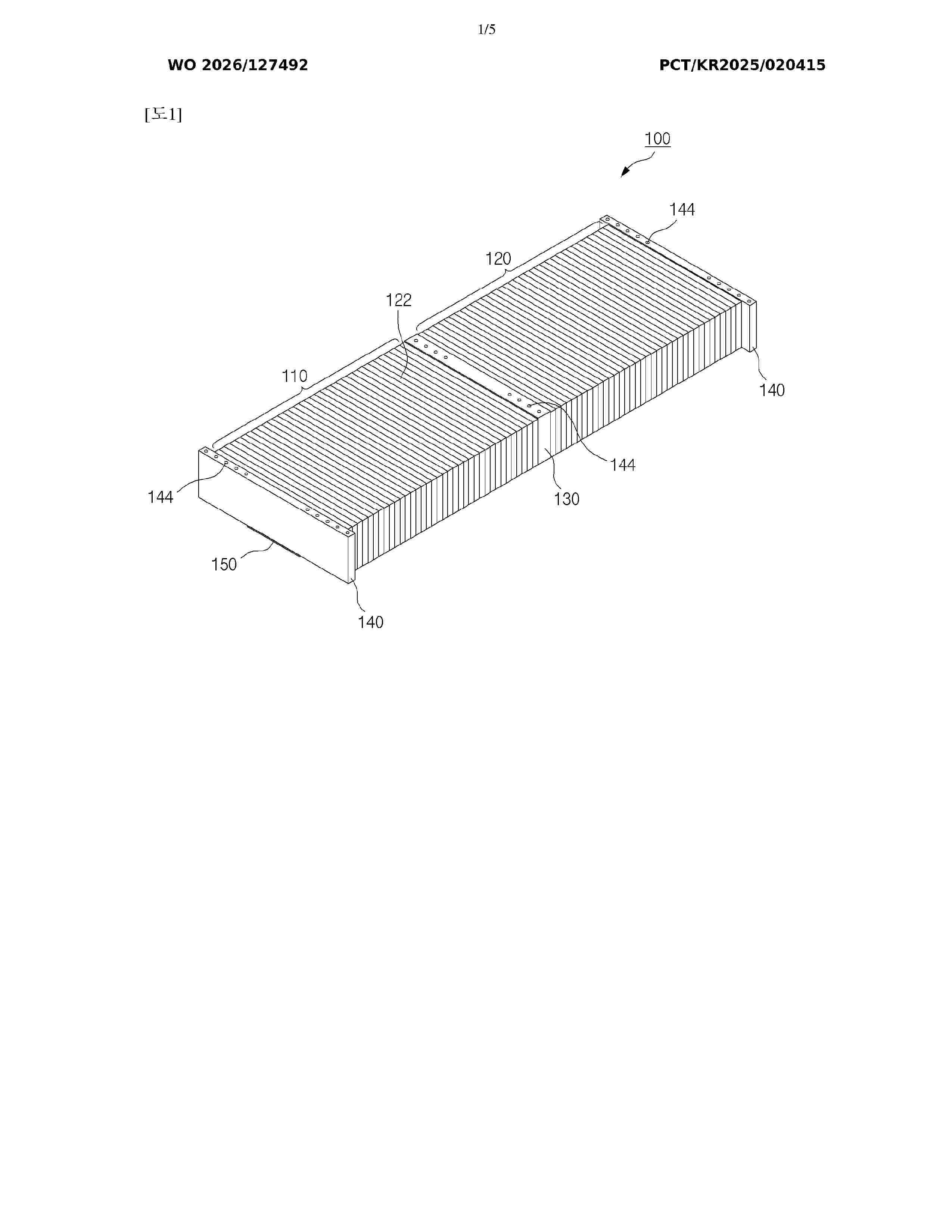
Resumen de: WO2026127492A1
The disclosed battery assembly comprises: a first cell array and a second cell array in which a plurality of battery cells are arranged in one direction; a beam pad disposed between the first cell array and the second cell array; a pair of side beams disposed outside each of the first cell array and the second cell array; and a support plate disposed on the bottom surfaces of the first cell array and the second cell array and fastened and fixed to the beam pad and the pair of side beams.
Resumen de: DE102025152736A1
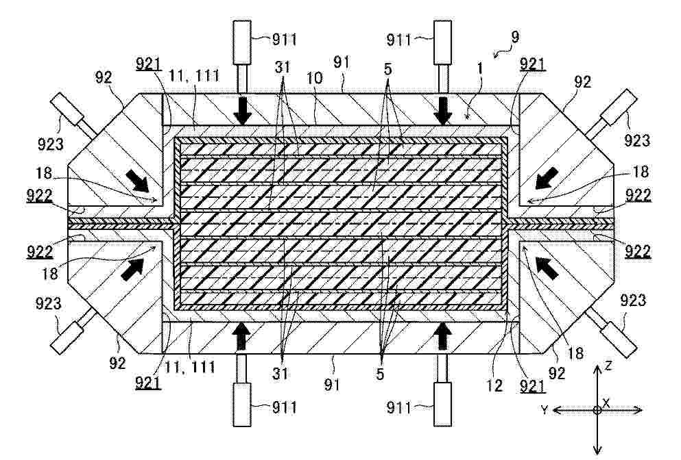
Problem Angemessenes Verschweißen von Harzstücken im Laufe der Herstellung einer Batteriezelle.Mittel zur Lösung Eine Herstellungsvorrichtung 9 für eine Batteriezelle 1 schließt ein: eine erste Heizplatte 91, die äußere Materialien 11, die einen Behälter 10 der Batteriezelle 1 bilden, und Harzstücke 5 in einer Schichtungsrichtung an einer Position einer Öffnung 12, 13 des Behälters 10 mit Druck beaufschlagt und erwärmt und dadurch die Öffnung versiegelt; und eine zweite Heizplatte 92, die Kanten der äußeren Materialien, die in der Schichtungsrichtung gestapelt sind, zumindest in der Schichtungsrichtung mit Druck beaufschlagt und erwärmt und dadurch einen Kantenabschnitt des Behälters versiegelt.
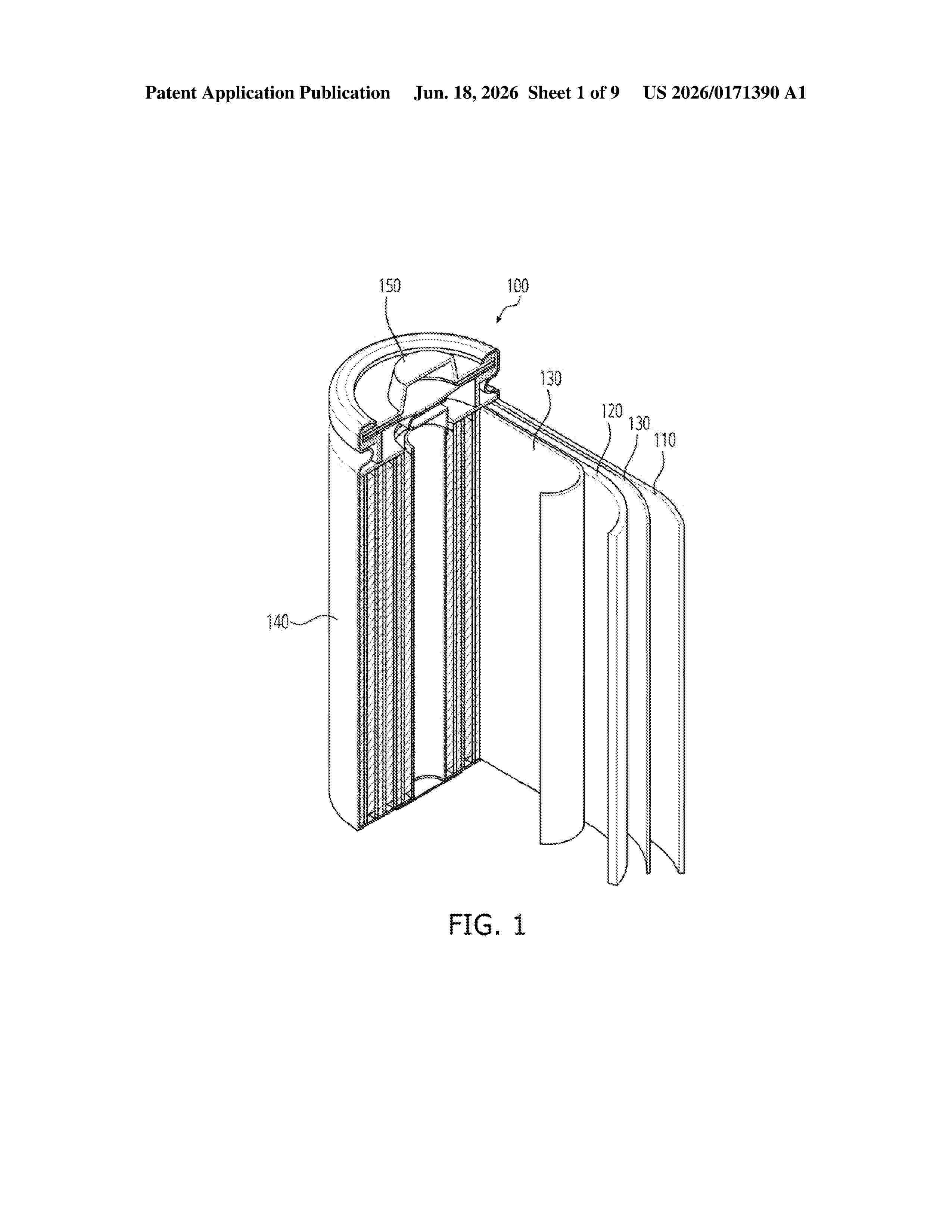
Resumen de: US20260171390A1
0000 A method of manufacturing an electrode plate includes applying an active material to a first region of a surface of a substrate, applying a temporary material to a second region of the surface of the substrate, pressing, through a press process, the substrate to which the active material and the temporary material are applied, and removing the temporary material to form the electrode plate.
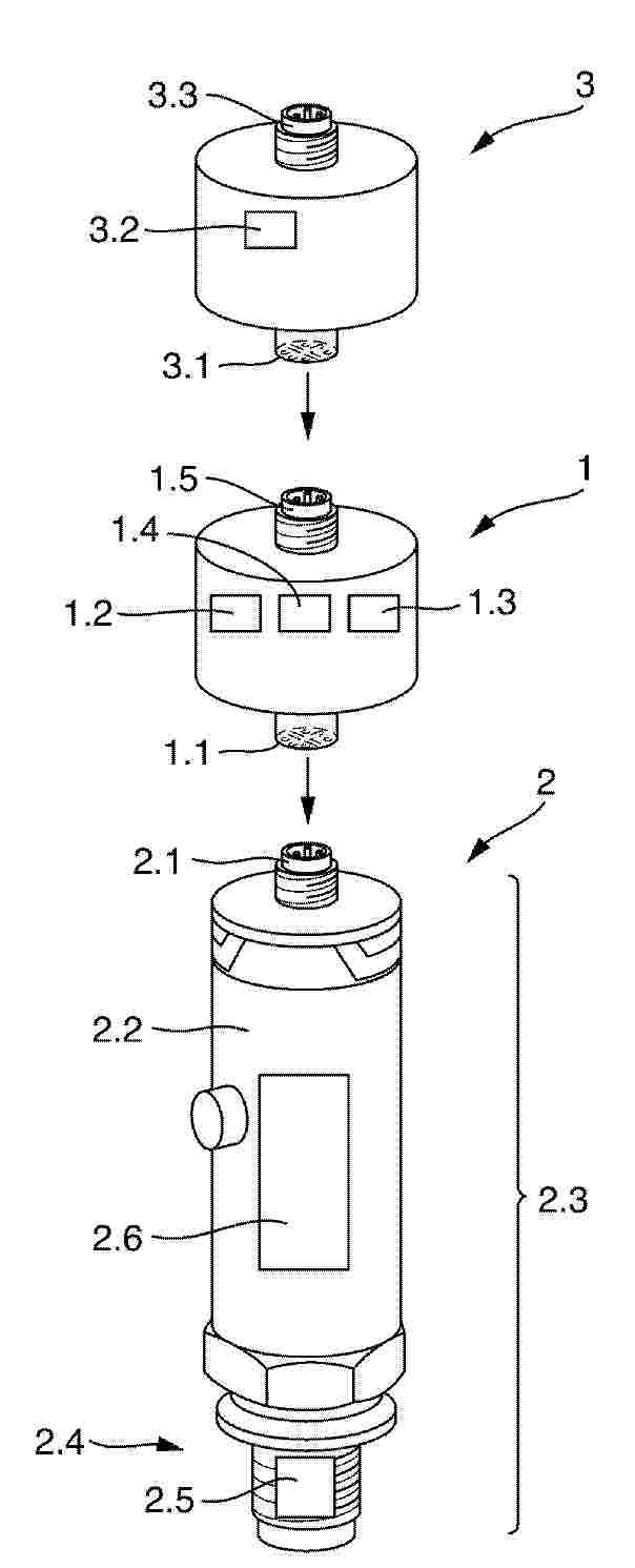
Resumen de: DE102024137619A1
Akkupack (1) für ein Feldgerät der Automatisierungstechnik (2), zumindest aufweisend einen M12-Steckverbinderbuchse (1.1) zum Anschließen des Akkupackes an einen M12-Steckverbinder (2.1) des Feldgerätes, zumindest eine Akkuzelle (1.2), die dazu ausgelegt ist, dass Feldgerät zumindest zeitweise über die M12-Steckverbinderbuchse mit Energie zu versorgen, ein Funkmodul (1.3), das dazu eingerichtet ist, Daten von dem an der M12-Steckverbinderbuchse (1.1) angeschlossenen Feldgerät (2) über die M12-Steckverbinderbuchse (1.1) zu empfangen und drahtlos auszusenden und eine Steuereinheit (1.4), die dazu eingerichtet ist, das an der M12-Steckverbinderbuchse (1.1) angeschlossene Feldgerät (2) zumindest zeitweise zu aktivieren und mit Energie zu versorgen, so dass das Feldgerät (2) im aktivierten Zustand Daten, insb. Messwerte, über die M12-Steckverbinderbuchse (1.1) zu dem Akkupack (1) überträgt und das Funkmodul (1.3) des Akkupacks die Daten drahtlos aussendet.
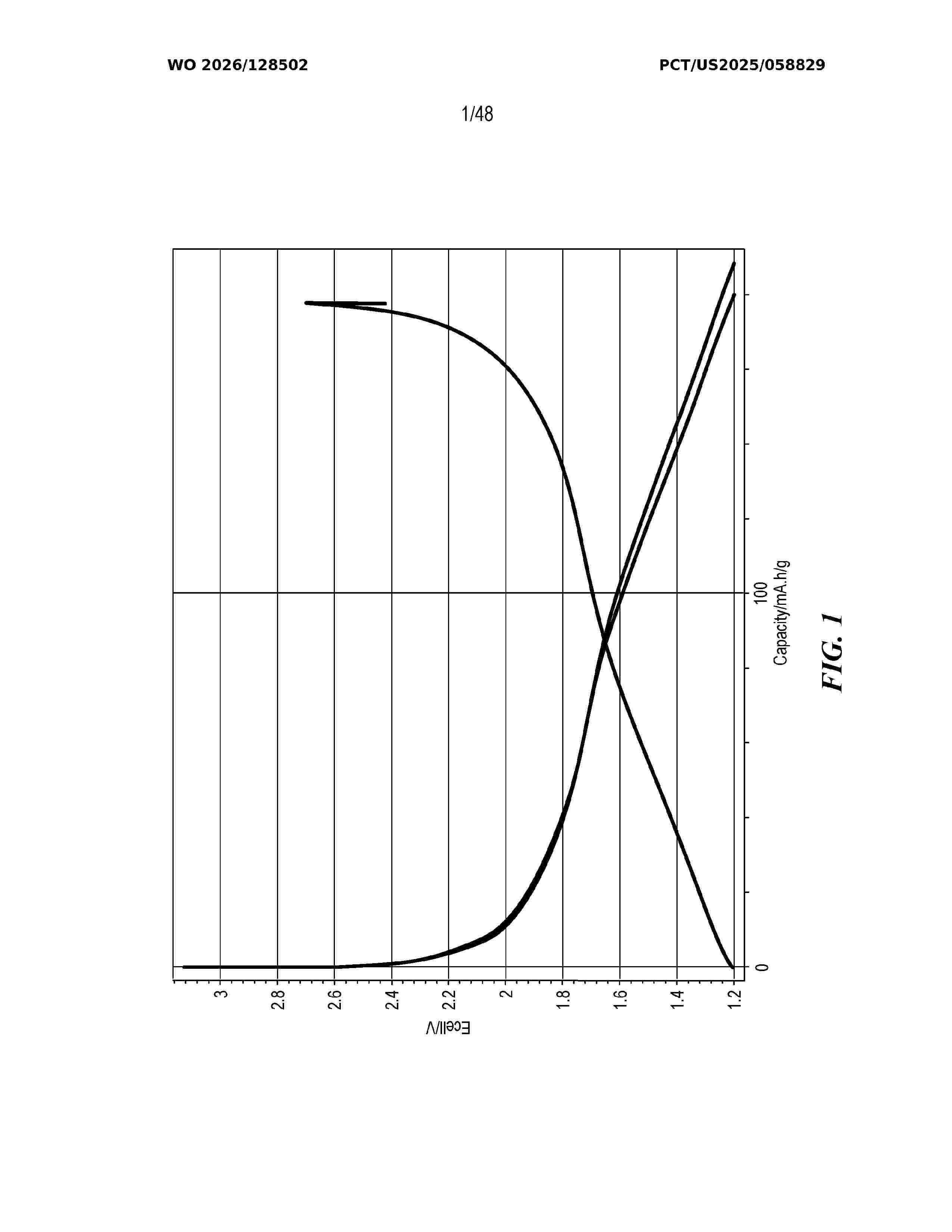
Resumen de: WO2026128502A1
Disclosed are methods, materials, compositions, formulations, products, and systems that pertain to energy storage devices such as Li-ion electrochemical cells and batteries. In some disclosed materials, the material has a crystal structure with one or more tetrahedral sites and a redox-inactive cation is located at each tetrahedral site. The disclosed embodiments, among other features and benefits, can be implemented to provide high-performance energy storage devices.
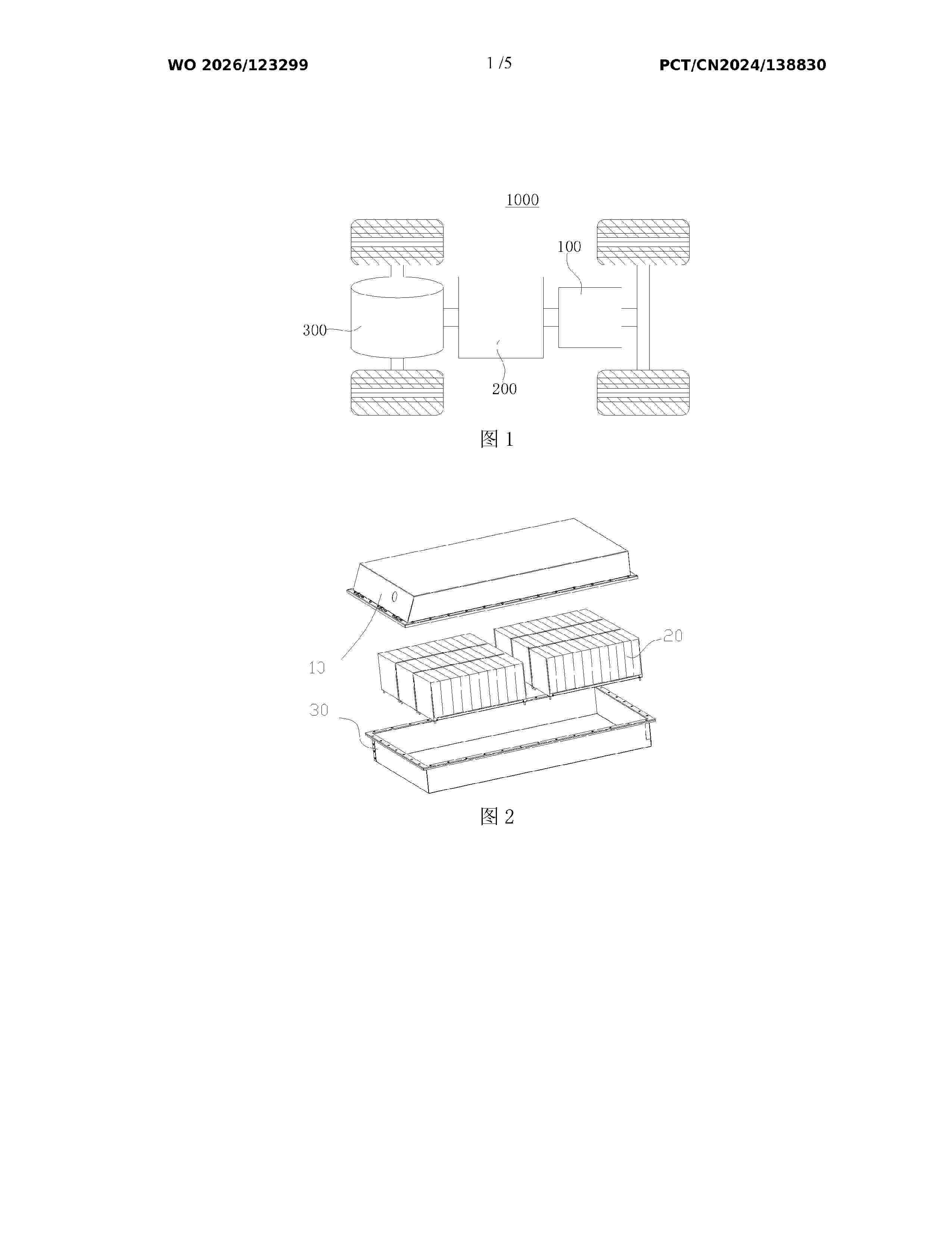
Resumen de: WO2026123299A1
Disclosed in the present application are a battery cell, a battery device, and an electric device. The battery cell comprises a housing, an electrode assembly, and a hydrogen-absorbing layer. The electrode assembly is disposed inside the housing and comprises a positive electrode sheet and a negative electrode sheet. The positive electrode sheet comprises a positive current collector and a positive active material layer disposed on the positive current collector. The negative electrode sheet comprises a negative current collector, and the negative current collector protrudes beyond the positive active material layer in a first direction, the first direction being perpendicular to a direction of thickness of the negative current collector. The hydrogen-absorbing layer is disposed on a portion of the negative current collector that protrudes beyond the positive active material layer in the first direction. The present application can improve the energy density of the battery cell.
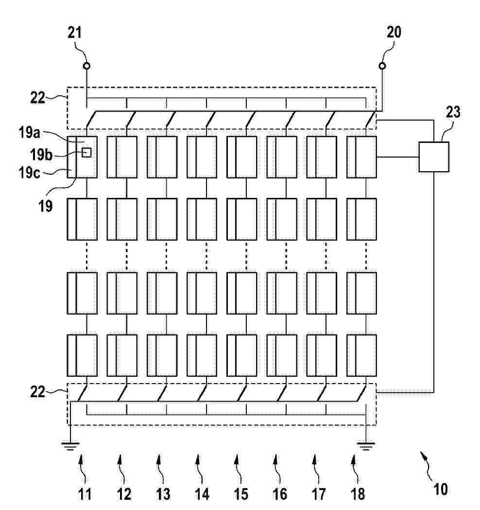
Resumen de: DE102024137426A1
Die Erfindung betrifft eine Zweitlebensdauer-Batterie (10) aufweisend- eine Vielzahl von Batteriezellengruppen (19), die in mehreren Strängen angeordnet sind und von denen jede eine Vielzahl von wiederverwendeten Zellen (19b) enthält, die identische oder ähnliche elektrochemische Eigenschaften aufweisen;- ein selektives Schaltsystem (22) mit unabhängigen elektrischen Verbindungen und Schaltern, die eine Manipulation der genannten Batteriezellengruppen (19) auf einer Strang-für-Strang-Basis ermöglichen; und- eine Steuereinheit (23), die mit den Batteriezellengruppen (19) und dem selektiven Schaltsystem (22) verbunden ist,- wobei die Steuereinheit (23) eingerichtet ist, einen Zellenausgleich der Batterie (10) durchzuführen:- durch Manipulieren des selektiven Schaltsystems (22) mit einem der Modi Laden, Entladen oder Ruheposition, so dass die Spannung jedes Stranges auf einen vorbestimmten Spannungswert der Klemmenspannung eingestellt wird,- durch Verwendung des vorbestimmten Spannungswertes als eine Ausgleichsreferenz, wobei der vorbestimmte Spannungswert ein mittlerer Spannungswert (40) der Zellenspannungen aller wiederverwendeten Zellen (19b) ist, die in den Batteriezellengruppen (19) enthalten sind.
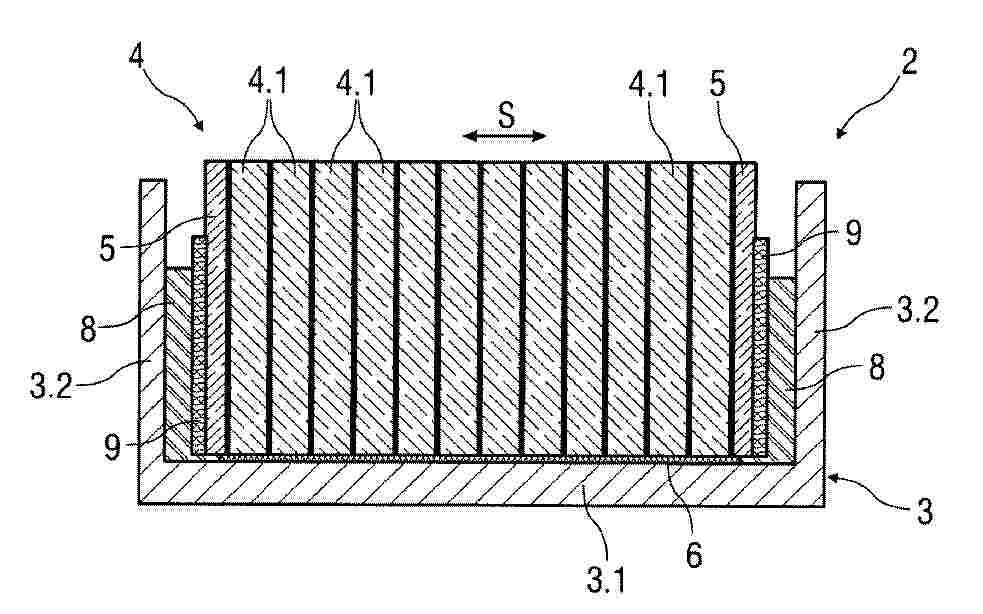
Resumen de: DE102024004401A1
Die Erfindung betrifft einen elektrischen Energiespeicher (2) für ein Fahrzeug (1) mit zumindest einem in einem Gehäuse (3) angeordneten Zellmodul (4), welches eine Anzahl von elektrisch miteinander verbundenen Einzelzellen (4.1) aufweist, die einen Zellstapel bilden, wobei in Stapelrichtung (S) jeweils endseitig eine Endplatte (5) an dem Zellstapel angeordnet ist. Erfindungsgemäß ist vorgesehen, dass an einer freien Flachseite der jeweiligen Endplatte (5) zwischen dieser und dem Gehäuse (3) ein Kompressionselement (9) zur Kompensation eines Zelldickenwachstums der Einzelzellen (4.1) angeordnet ist. Weiterhin betrifft die Erfindung ein Verfahren zur Herstellung des elektrischen Energiespeichers (2) und ein Fahrzeug (1) mit einem solchen.
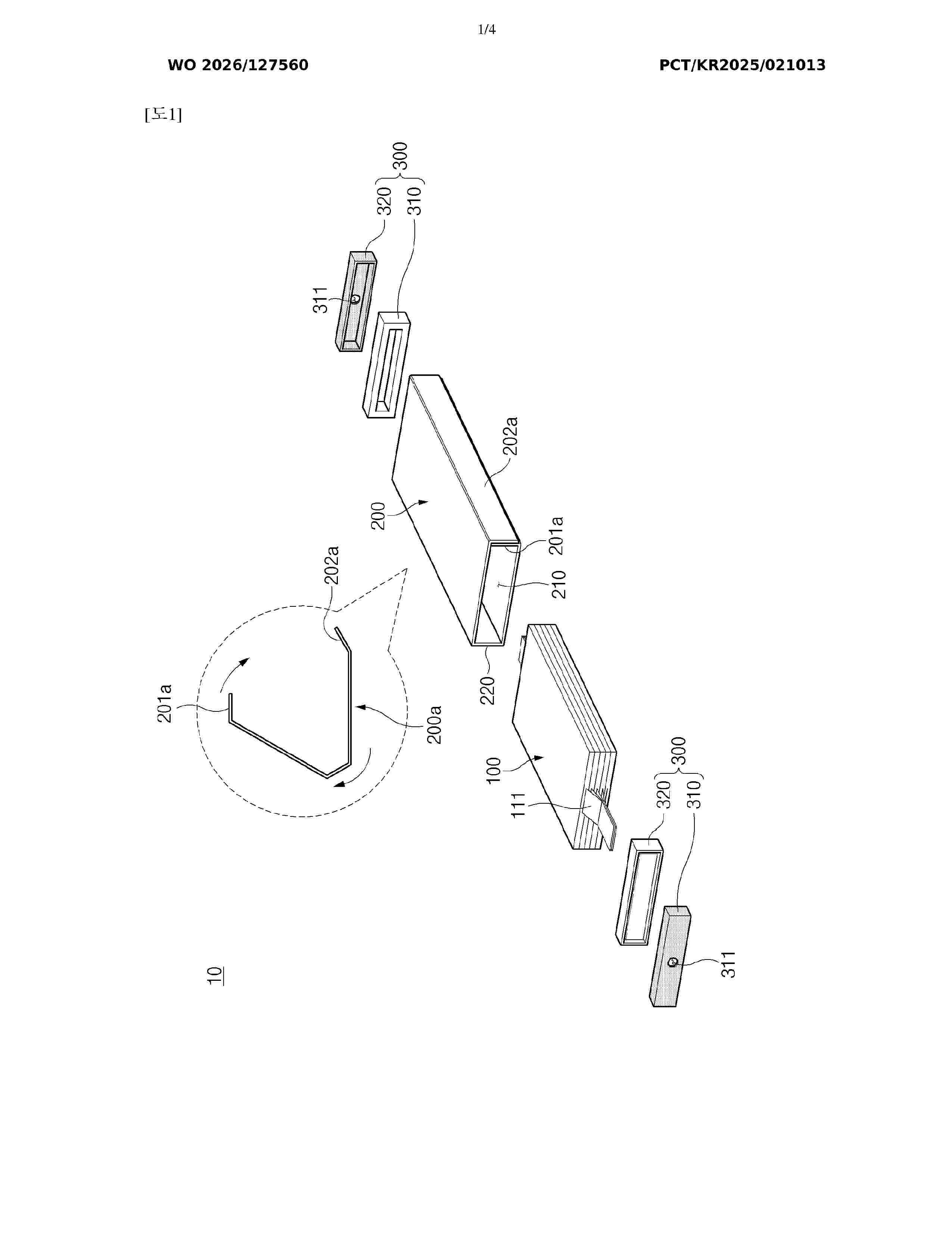
Resumen de: WO2026127560A1
The present invention relates to a chargeable/dischargeable secondary battery. The secondary battery, according to one embodiment of the present invention, may comprise: an electrode assembly; a sheet-type exterior material provided with an inner space for receiving the electrode assembly therein, and an exterior material opening enabling the inner space to communicate with the outside; a cap coupled to the sheet-type exterior material by being inserted into the exterior material opening; and a pressing member receiving heat and expanding, thereby pressing a coupling portion where the sheet-type exterior material and the cap are coupled.
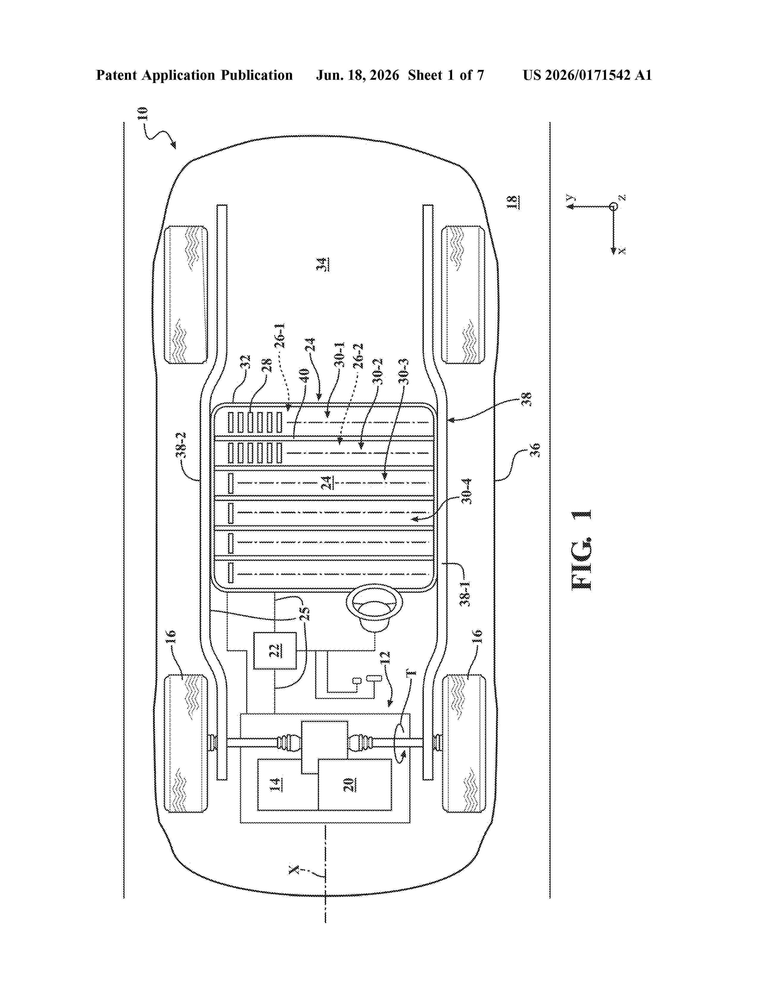
Resumen de: US20260171542A1
0000 A motor vehicle includes a vehicle body structure including a vehicle frame having parallel frame rails. The motor vehicle also includes a powerplant supported by the vehicle frame and configured to generate torque and a multi-cell rechargeable energy storage system (RESS) having a plurality of battery cells configured to supply electrical energy to the powerplant. The motor vehicle additionally includes a structural member positioned perpendicular to and fixed to each of the parallel frame rails, thereby reinforcing the vehicle frame. The structural member is arranged proximate to the RESS. At least one coolant passage is arranged within the structural member and is configured to circulate coolant to adjust temperature of the plurality of battery cells.
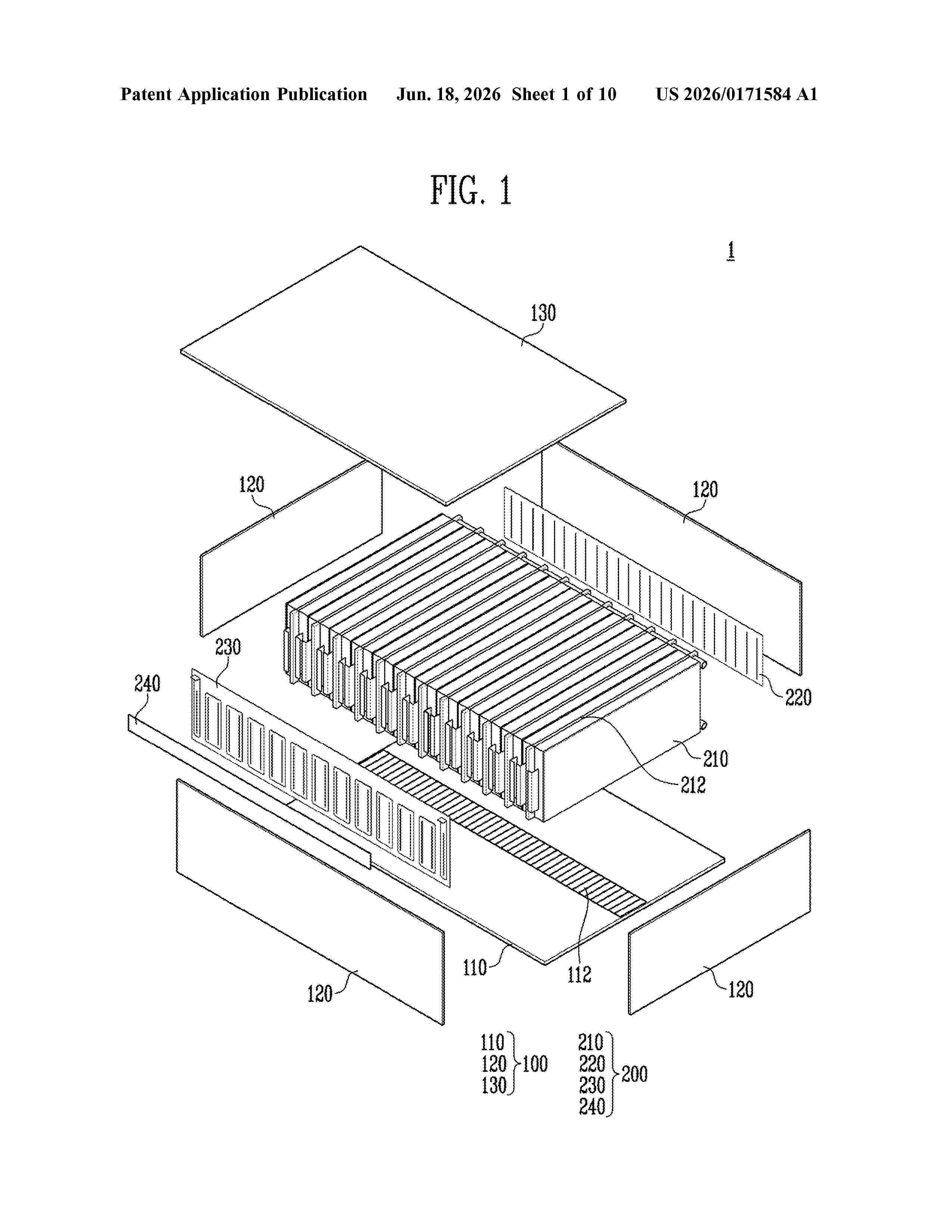
Resumen de: US20260171584A1
The present disclosure relates to a battery assembly. Such a battery assembly includes a case in which a receiving space is formed inside, a plurality of battery cells stacked in a predetermined direction, and a cell assembly accommodated in the receiving space. The cell assembly includes a printed wiring circuit board for measuring a voltage of at least one of the battery cells, and a cooling plate which is formed of an electrically conductive material, has a flow path formed therein through which a cooling material moves, and is disposed to face the battery cells. One electrode of each of the battery cells is electrically connected to the printed wiring circuit board through the cooling plate, and the other electrode of each of the battery cells is formed to be electrically connected to the printed wiring circuit board.
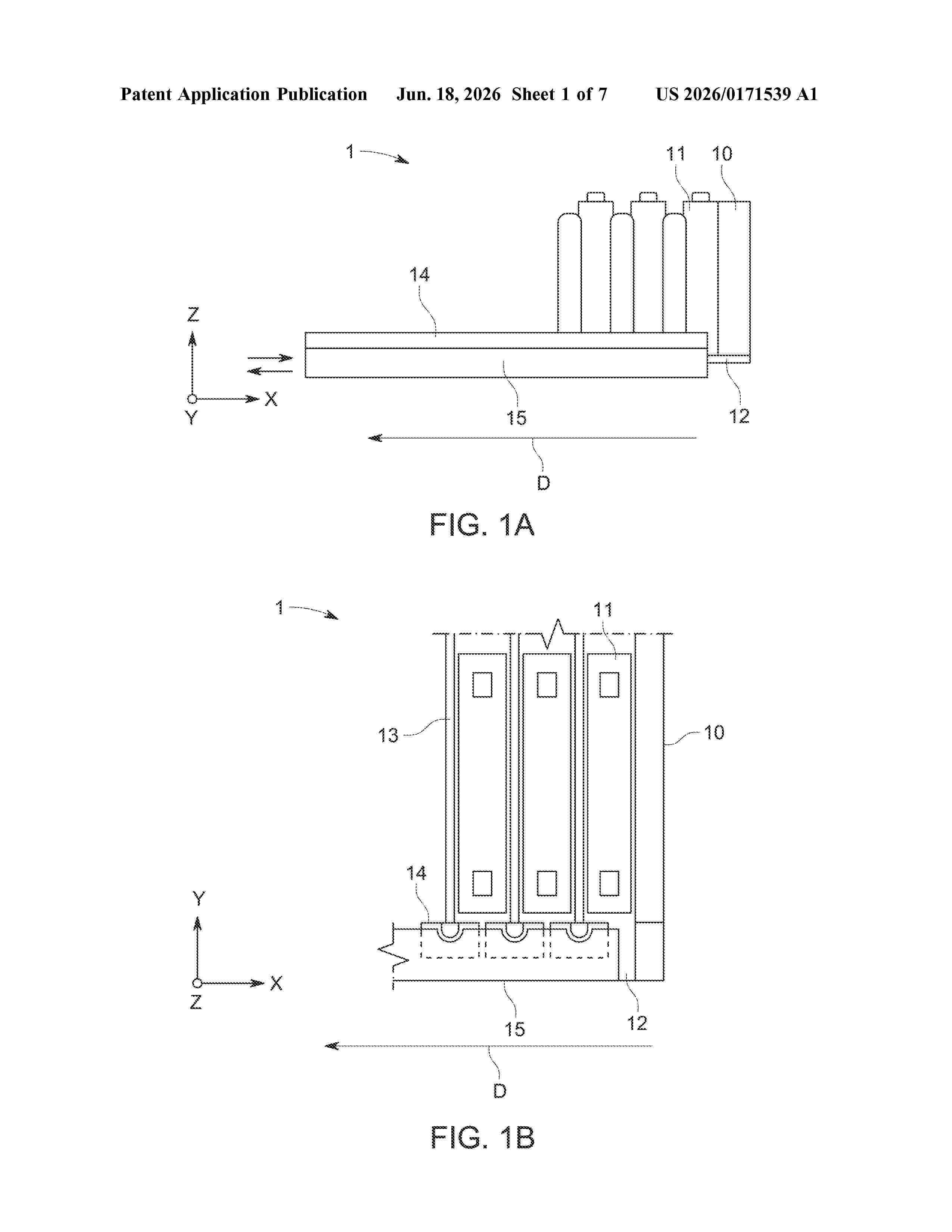
Resumen de: US20260171539A1
0000 The present disclosure refers to a battery module. The battery module includes a module base plate and battery cells stacked in a stacking direction on the module base plate. Further, the battery module includes at least one cooling element with a connector, wherein the cooling element is disposed on the module base plate, and at least one module cooling element connector which extends along at least a part of the stacking direction on a side of the module base plate opposite to the cooling element. The module cooling element connector includes a cooling element portion which is connected to the connector of the cooling element via a fluid connecting element of the module base plate and via sealings between the cooling element portion, the module base plate and the connector of the cooling element, wherein a flow path is formed between the cooling element portion, the module base plate and the connector of the cooling element. The module cooling element connector further includes a clamping clip portion configured to engage with the connector of the cooling element for pulling the cooling element portion and the connector towards the module base plate such that a sealing force is provided onto the sealings by the clamping clip portion.
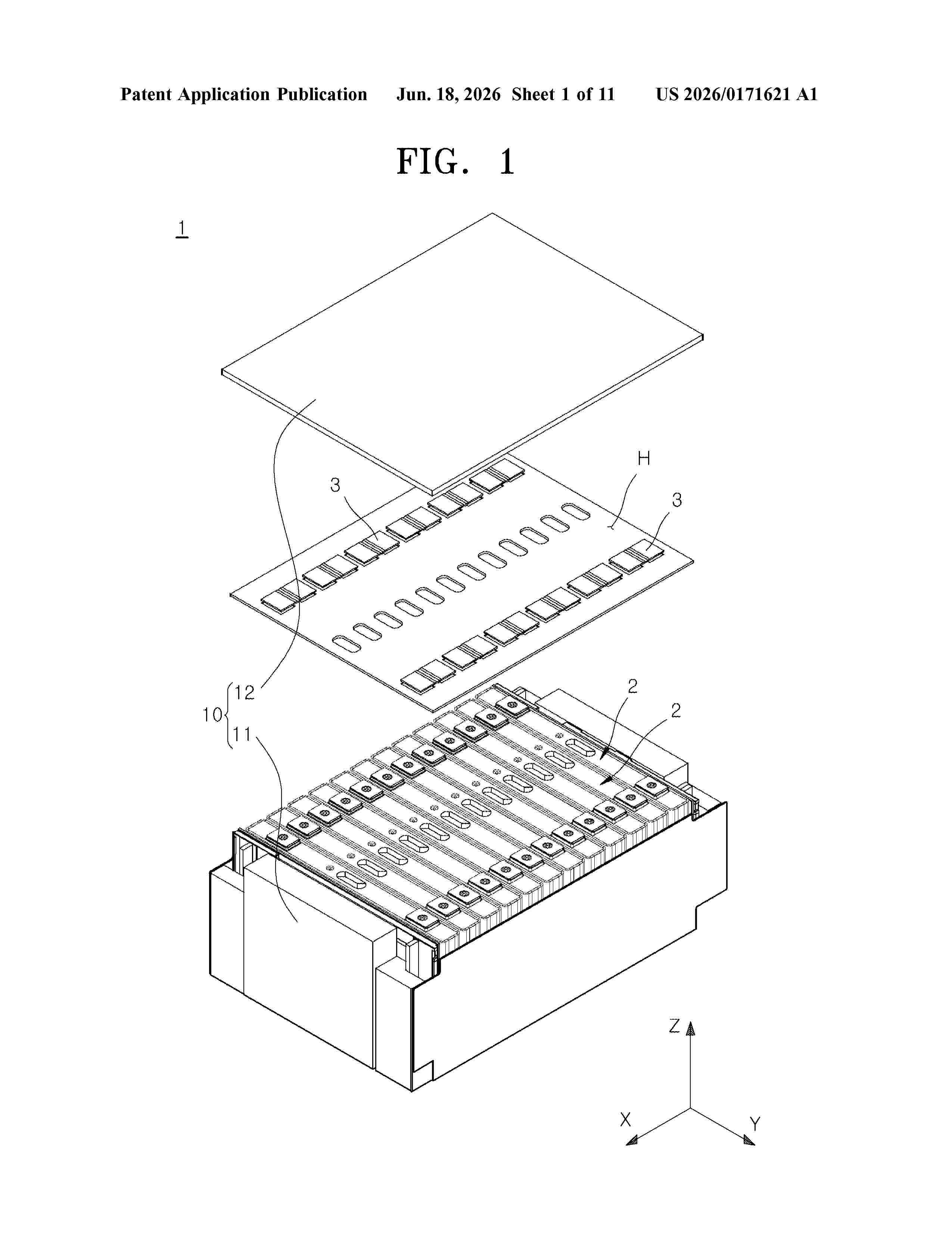
Resumen de: US20260171621A1
The present disclosure relates to a secondary battery and a battery pack including the secondary battery. The secondary battery includes: a case having one open side, the case including a plurality of walls defining an internal space; an electrode assembly accommodated in the internal space; a cap plate configured to close the one open side of the case; a first terminal disposed on the cap plate; a first plate disposed between one of the plurality of walls and the electrode assembly in the internal space, the first plate including a first current collector connecting portion; and a first current collector including a first terminal connecting portion and a first plate connecting portion, the first terminal connecting portion electrically coupled to the first terminal, the first plate connecting portion electrically connected to the first terminal connecting portion and including a first welding surface facing away from the one of the plurality of walls, the first welding surface welded to the first current collector connecting portion.
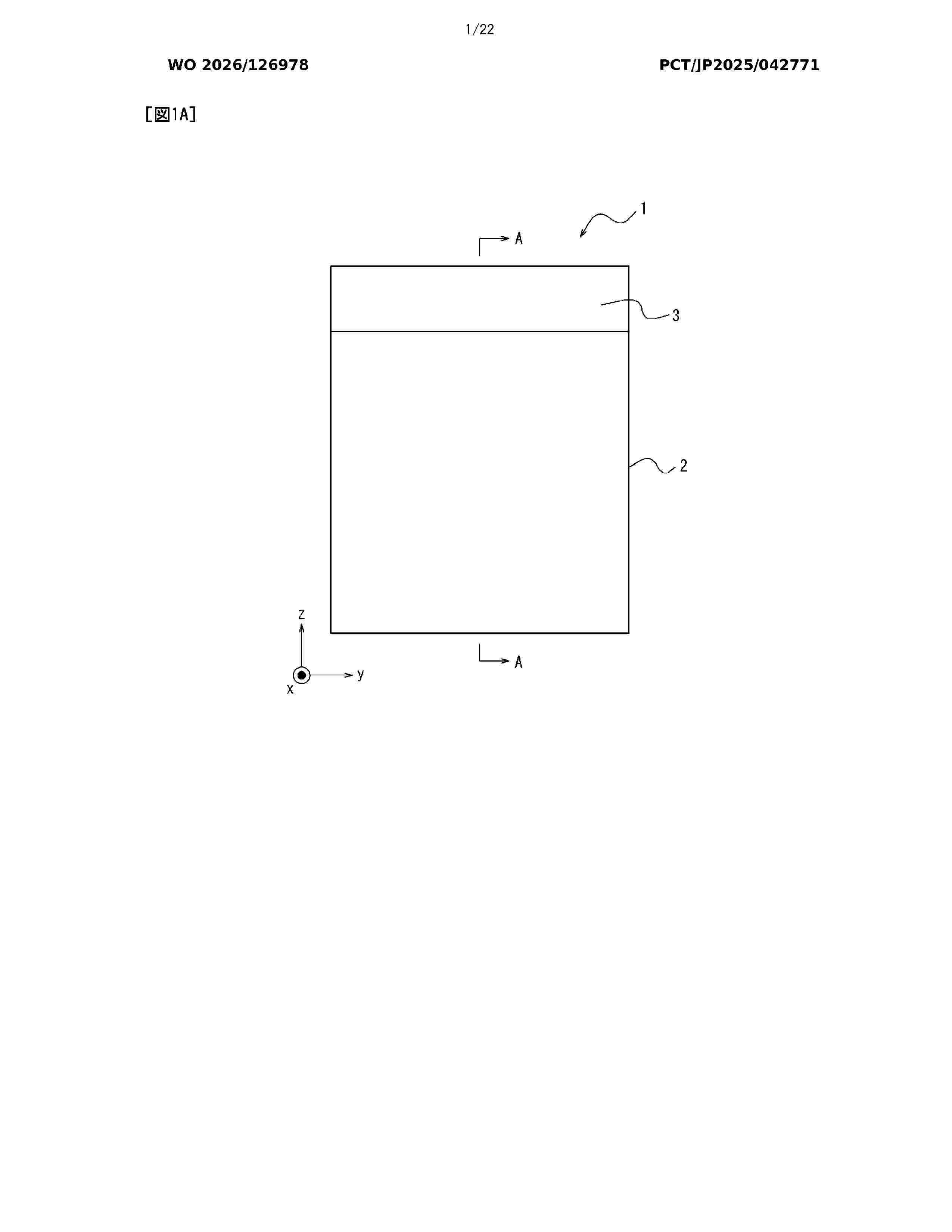
Resumen de: WO2026126978A1
The present disclosure addresses the problem of providing a heat absorber that can absorb the expansion of a battery cell by being sufficiently deformed in accordance with the expansion of the battery cell and has a restoring force for restoring the heat absorber to a shape before deformation. The solution is a heat absorber (1) comprising: a content (4) containing an aqueous solvent; a bag body (2) having a filling section (5) filled with the content (4) and an accommodation section (6) capable of accommodating the content (4) deformed by the application of an external force to the filling section (5); and a restoration member (3) that returns the content (4) accommodated in the accommodation section (6) to the filling section (5), wherein a deformed state in which the content (4) is accommodated in the accommodation section (6) due to the deformation of the filling section (5) caused by the external force, and a normal state in which the content (4) accommodated in the accommodation section (6) is returned into the filling section (5) by the restoration member (3) are reversible.
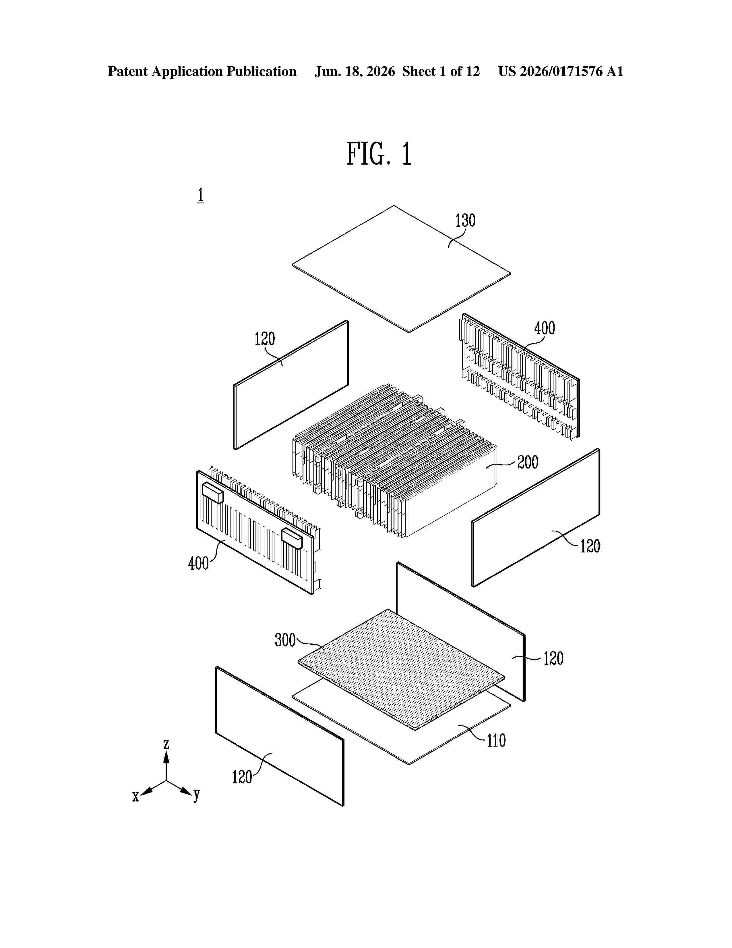
Resumen de: US20260171576A1
0000 The present disclosure relates to a battery assembly and a method of manufacturing the same. The battery assembly includes a case comprising a lower plate, a side plate connected to the lower plate to form a receiving space together with the lower plate, and an upper plate coupled to the side plate to seal the receiving space; a plurality of battery cells coupled to the lower plate and accommodated in the receiving space; and an adhesive layer disposed between the lower plate and the plurality of battery cells and adhering the lower plate and one surface of each of the plurality of battery cells, wherein the adhesive layer Includes a reinforcement member at least a portion of which is prevented from being deformed in shape by a load applied from the plurality of battery cells.
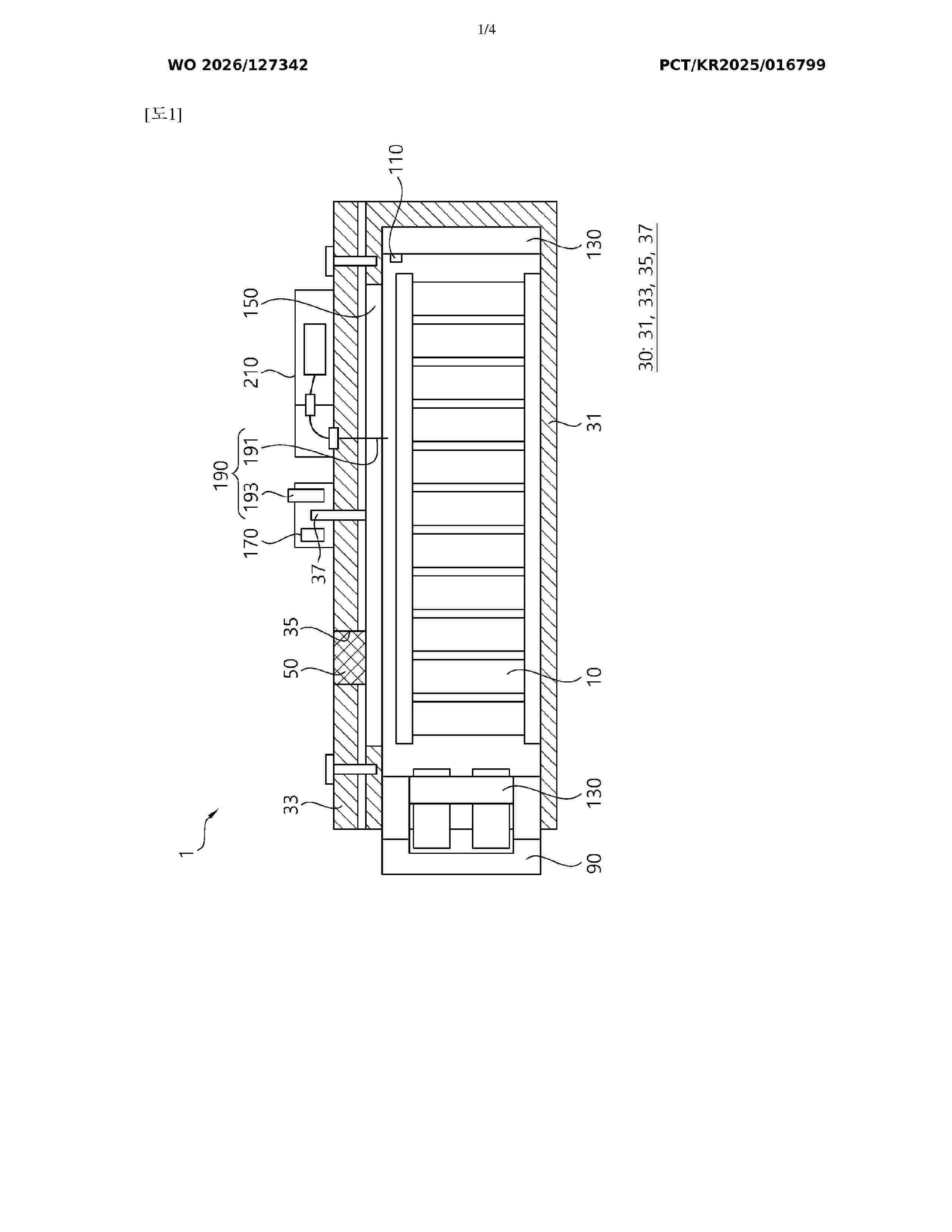
Resumen de: WO2026127342A1
A battery assembly for preventing thermal runaway according to the present invention comprises: a plurality of battery cells; a battery pack which defines an accommodation space for accommodating the plurality of battery cells electrically connected to each other and protects the plurality of battery cells from the outside; a fire-extinguishing coolant filled in the battery pack and including any one of a liquid non-conductive aqueous material and a gel-phase non-conductive aqueous mixture in which a non-conductive aqueous material and a superabsorbent resin are mixed; and a coolant supply unit selectively coupled to and decoupled from the battery pack and configured to supply the non-conductive aqueous material into the battery pack on the basis of the level of the fire-extinguishing coolant filled in the battery pack.
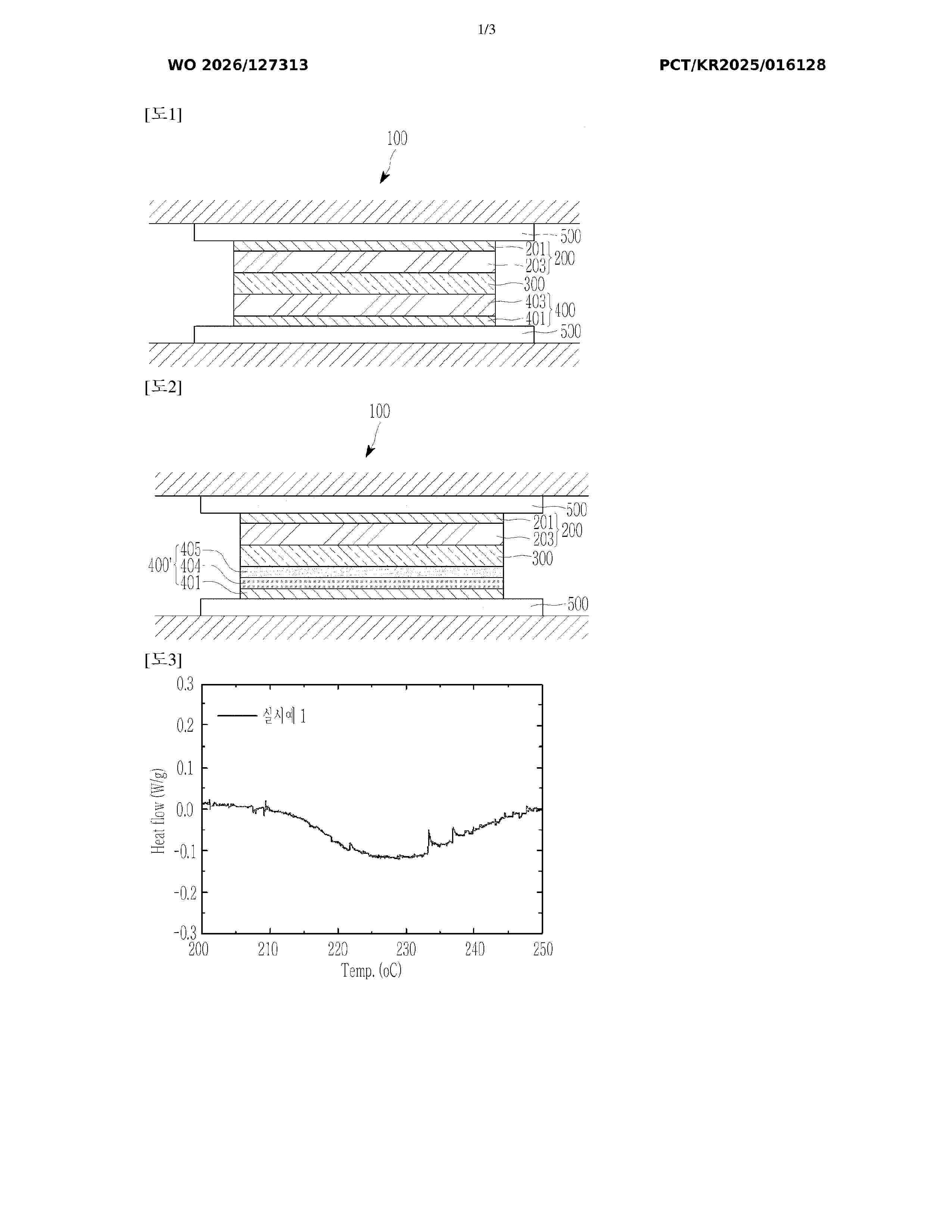
Resumen de: WO2026127313A1
The present invention relates to a positive electrode and an all-solid-state secondary battery including same, the positive electrode including a sulfide-based solid electrolyte and a sulfur-containing additive that is glass or glass-ceramic and that exhibits an endothermic peak at 180°C to 220°C in differential scanning calorimetry (DSC) analysis.
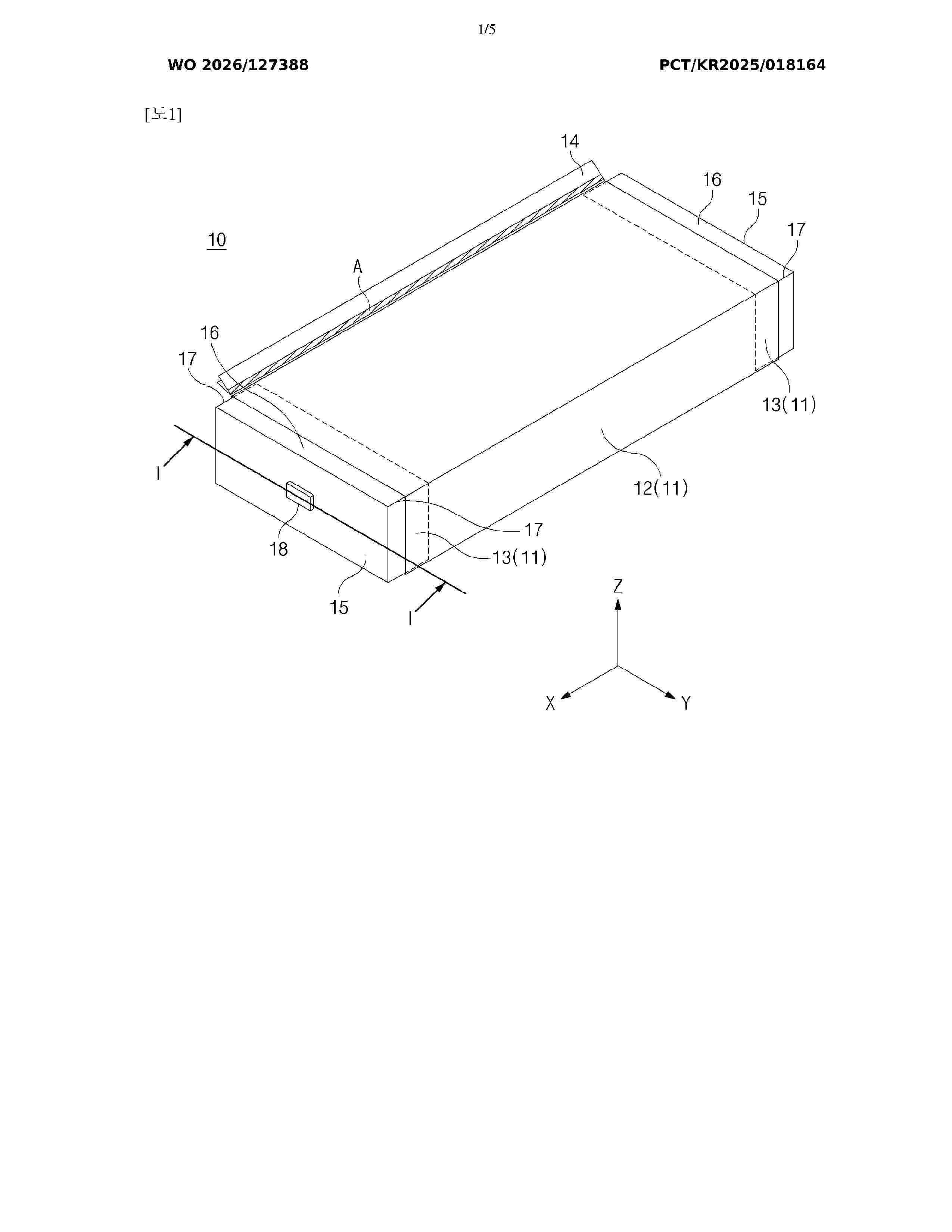
Resumen de: WO2026127388A1
The present invention relates to a device and method for manufacturing a secondary battery. The device for manufacturing a secondary battery, according to an aspect of the present invention, is a manufacturing device which processes a subassembly to manufacture a secondary battery, the subassembly comprising: an electrode assembly; a cap covering one side of the electrode assembly; and an accommodation unit surrounding a plurality of circumferential surfaces of the cap and the electrode assembly and made of exterior films. The device may comprise: a position correction unit capable of moving an extension unit toward an edge disposed between neighboring circumferential surfaces among the plurality of circumferential surfaces, the extension unit extending from the accommodation unit toward the outside of the cap; and a coupling unit capable of coupling the plurality of circumferential surfaces and the accommodation unit.
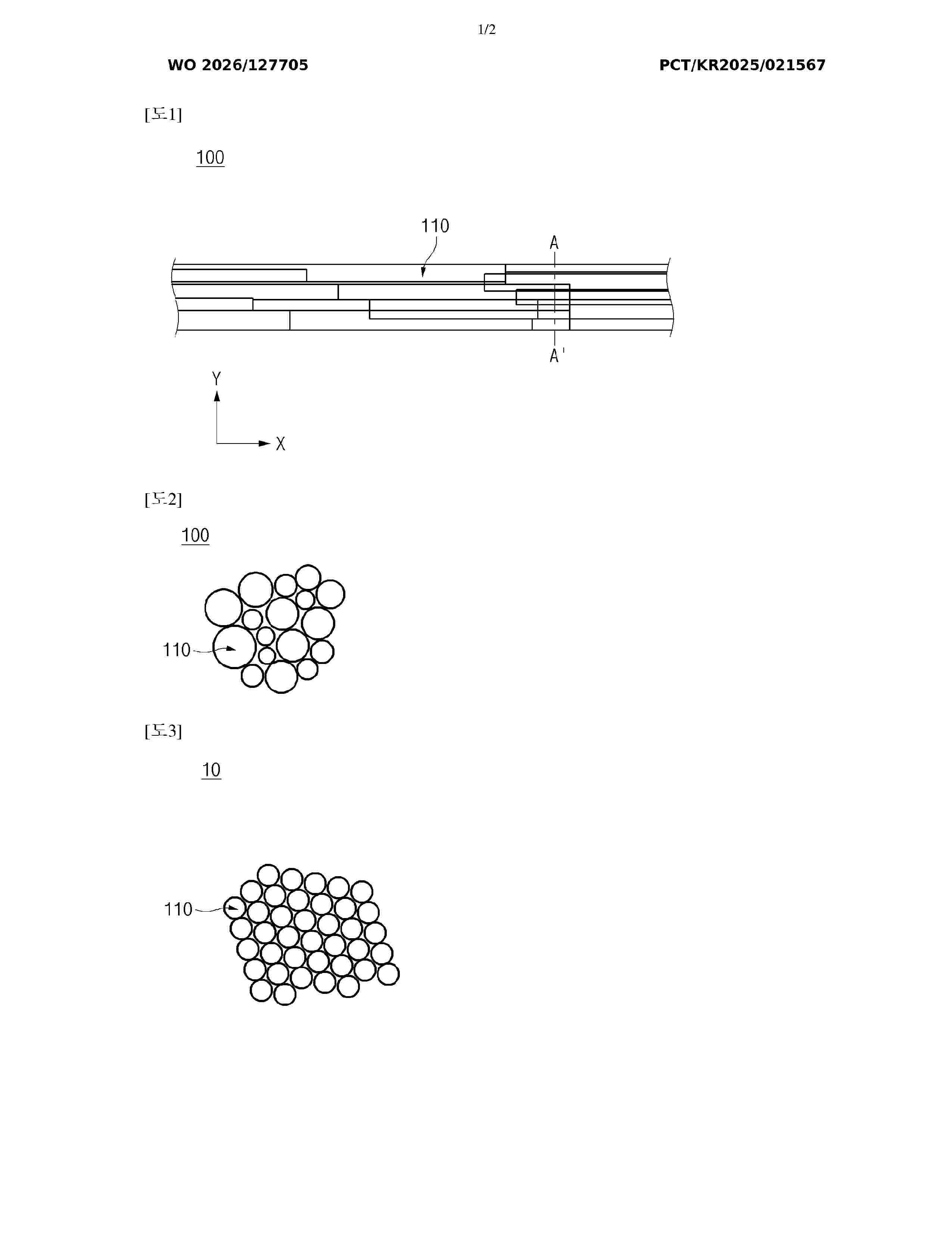
Resumen de: WO2026127705A1
Disclosed in the present specification are a conductive material dispersion and an electrode using the dispersion, wherein the conductive material dispersion comprises carbon nanocables, an amine-based dispersant, and a polyphenol-based dispersant, the carbon nanocables have an average diameter of 1 ㎛ or less and are obtained by arranging and bonding a plurality of carbon nanotube units, including single-walled carbon nanotubes and double-walled carbon nanotubes, in the longitudinal direction and the radial direction, and the carbon nanotube units have an average diameter of 1.8 nm to 4.0 nm and a standard deviation of diameter of 0.30 or more. In addition, a secondary battery having improved resistance characteristics and lifespan characteristics due to the use of carbon nanocables having a high packing density, excellent durability, and a long length as a conductive material may be provided.
Nº publicación: DE102024138393A1 18/06/2026
Solicitante:
STIHL AG & CO KG ANDREAS [DE]
Andreas Stihl AG & Co. KG
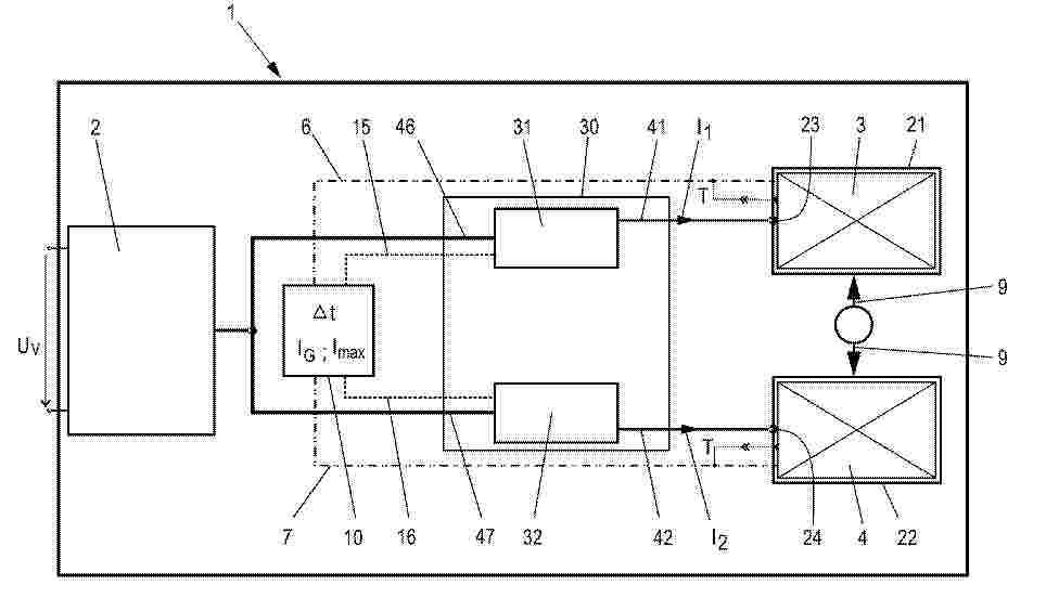
Resumen de: DE102024138393A1
Die Erfindung betrifft ein Verfahren zum Laden eines ersten Akkupacks (3; 4) und eines zweiten Akkupacks (4; 3) mit einem Ladegerät (1), wobei das Ladegerät (1) eine erste Schnittstelle (23; 24), eine zweite Schnittstelle (24; 23), zumindest eine Leistungselektronik (30) zur Bereitstellung einer Ladeleistung und eine Steuerung (10) umfasst. Der erste Akkupack (3; 4) wird über die erste Schnittstelle (23; 24) und der zweite Akkupack (4; 3) über die zweite Schnittstelle (24; 23) mit einer ersten Ladeleistung oder mit einer zweiten Ladeleistung geladen. Der ersten Schnittstelle (23; 24) wird die erste Ladeleistung zum Laden des ersten Akkupacks (3; 4) zugeführt. Die Steuerung (10) erfasst zumindest einen Betriebsparameter des aktiven Ladevorgangs an der ersten Schnittstelle (23; 24) und vergleicht diesen mit einem in der Steuerung (10) abgespeicherten Grenzwert. In Abhängigkeit des Ergebnisses des Vergleichs wird die Steuerung (10) der zweiten Schnittstelle (24; 23) die zweite Ladeleistung zum Laden des zweiten Akkupacks (4; 3) zuführen.
 BOPI
BOPI
 Sede Electrónica