Si deseas distinguir tus productos, servicios o ambos de los de otra empresa, es posible que necesites una marca o nombre comercial. Descubre qué son, en qué consiste su procedimiento de registro y qué implica.

Información sobre los plazos de presentación de solicitudes de transformación de marcas de la Unión Europea en marca nacional española. Más información


Si tienes un nuevo dispositivo, producto o procedimiento que resuelva un problema técnico o tenga una ventaja práctica, existen distintas formas de protegerlo en España y en otros países. Descubre cómo hacerlo.

¿Tu innovación reside en la estética, la ornamentación o la apariencia de tu producto? Protégela mediante un diseño industrial. Descubre qué derechos confiere el registro y cómo realizar la tramitación.

Las indicaciones geográficas protegen el nombre de un producto originario de una zona geográfica, a la cual le debe una determinada calidad, reputación u otra característica. Descubre qué son, en qué consiste su procedimiento de registro y qué beneficios conceden.

Las patentes publicadas en todo el mundo son una valiosa fuente de información científica, técnica y comercial.

Si eres emprendedor/a o una empresa y quieres potenciar y mejorar la rentabilidad de tu negocio protegiendo de forma adecuada los activos intangibles de tu organización, en este espacio encontrarás lo necesario.


 1500
resultados
1500
resultados
 Última actualización
27/06/2026 [07:57:00]
Última actualización
27/06/2026 [07:57:00]


 Resultados 250 a 275 de 1500

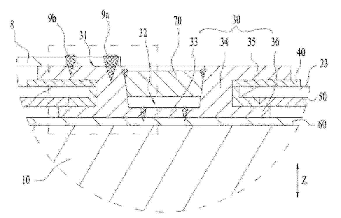
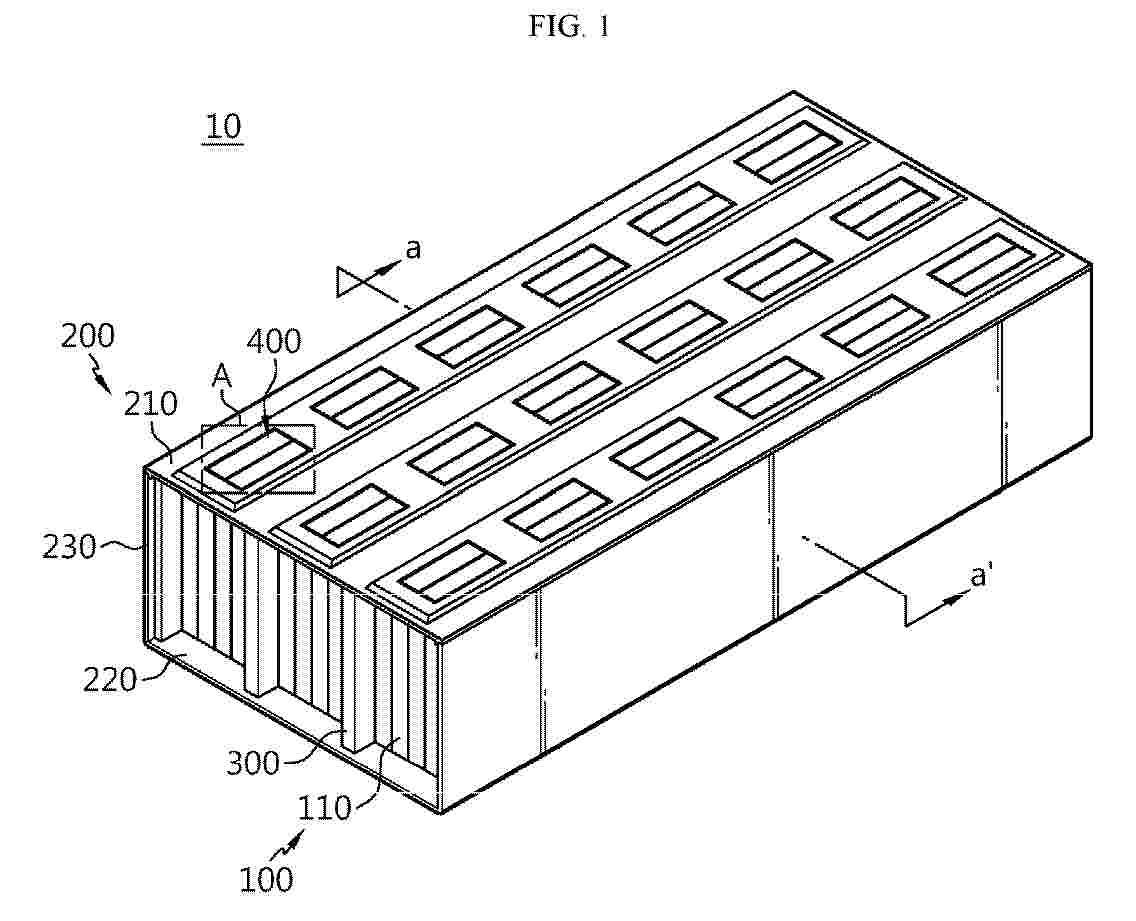
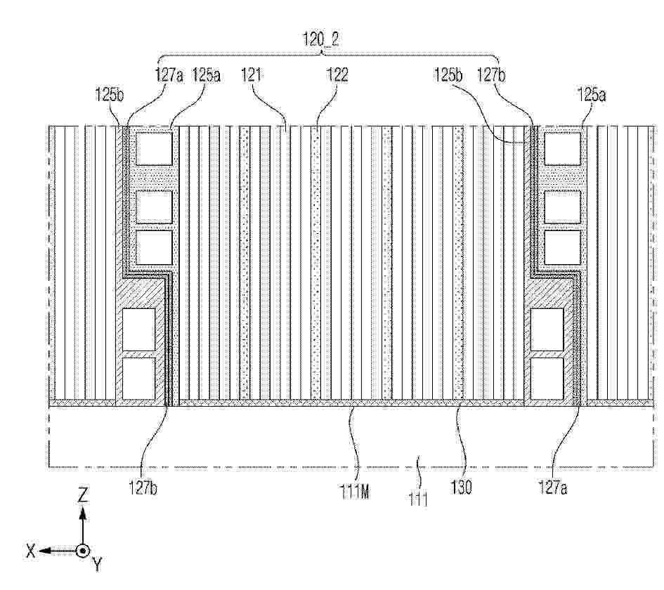
Resumen de: EP4765457A1
A battery cell (7), a battery (2), and an electrical apparatus. The battery cell (7) comprises a casing (20), an electrode assembly (10), and an electrode terminal (30). The casing (20) comprises a wall portion (23). The electrode assembly (10) is accommodated in the casing (20) and comprises tabs (12). The electrode terminal (30) is arranged on the wall portion (23); the side of the electrode terminal (30) away from the electrode assembly (10) in the thickness direction of the wall portion (23) is provided with an outer surface (31), the electrode terminal (30) is provided with a recessed portion (32) recessed from the outer surface (31), the electrode terminal (30) comprises a connecting portion (33) arranged at the bottom of the recessed portion (32), and the connecting portion (33) is electrically connected to the tabs (12).

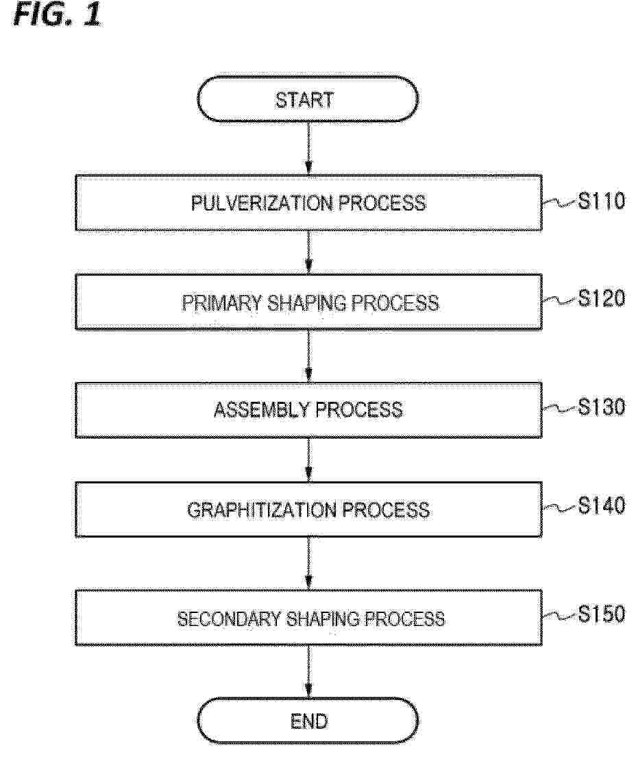
Resumen de: EP4765252A1
The present invention relates to a negative electrode active material. Specifically, the negative electrode active material comprises: artificial graphite particles; and a nitrogen element, an oxygen element, and a hydrogen element present on the surface of, inside, or both on the surface of and inside the artificial graphite particles, wherein the content of the nitrogen element is 80 to 180 mg per kg of the negative electrode active material.
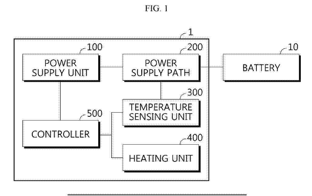
Resumen de: EP4764538A1
The present disclosure relates to a device for testing a battery having an electrode terminal, and the device may include: a power supply unit configured to supply power; a power supply path having one end connected to the electrode terminal and the other end connected to the power supply unit, and configured to provide a path through which power is supplied from the power supply unit to the electrode terminal; a temperature sensing unit disposed at least on one side of the power supply path and configured to measure a temperature of the power supply path; a heating unit disposed at least on one side of the power supply path and configured to apply heat to the power supply path; and a controller configured to control the heat application of the heating unit depending on a temperature measurement result of the temperature sensing unit.
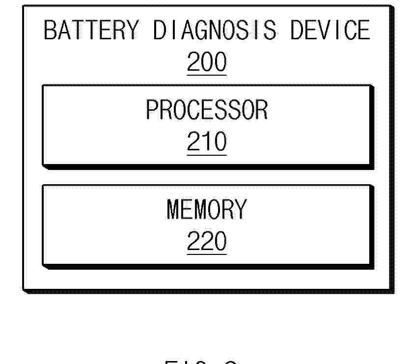
Resumen de: EP4764571A1
A battery management device according to an embodiment of this document includes a memory configured to store at least one instruction and a processor configured to execute the at least one instruction, and the processor is configured to acquire incremental capacity data based on charging and discharging data for a plurality of battery cells, identify reference incremental capacity values of the plurality of battery cells corresponding to voltages of each of the plurality of battery cells using the incremental capacity data, and acquire a target voltage for diagnosing a state of the battery cell using the reference incremental capacity values.
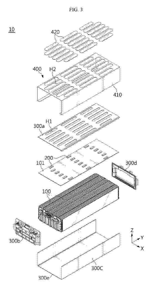
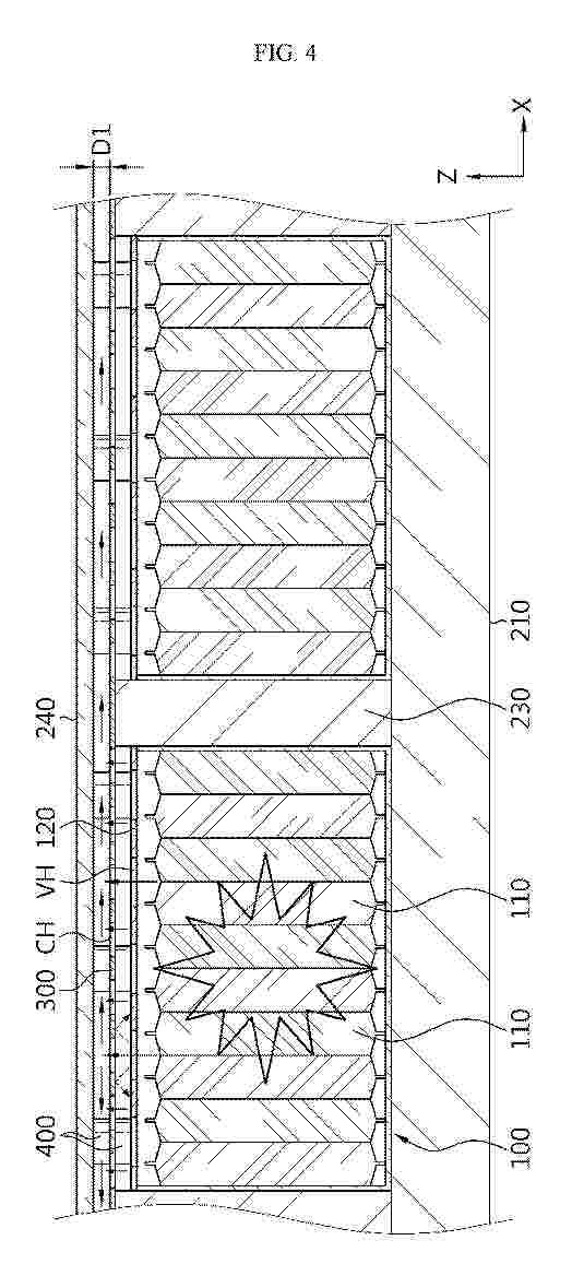
Resumen de: EP4765424A1
0001 The present disclosure may provide a battery module that includes a plurality of battery cells, a top cover configured to cover one surface of the plurality of battery cells, and at least one thermal deformation member disposed between the top cover and the battery cells, and configured to expand in volume and deform a portion of the top cover when a temperature reaches a preset temperature or higher due to heat.
Resumen de: EP4765431A1
The present disclosure relates to a battery pack including: a plurality of battery modules including a plurality of battery cells; a pack case having a storage space formed to store the plurality of battery modules; a cover member provided between the battery modules and the pack case, and having a through-hole formed to allow venting gas discharged from the battery cells to pass therethrough; and a spacer mounted to the cover member and configured to maintain a gap between the cover member and the pack case.
Resumen de: EP4763935A1
The present invention relates to an adhesive film including an outer insulating layer; and an adhesive layer disposed on one surface of the outer insulating layer, wherein the adhesive layer includes a thermosetting resin, and the adhesive film satisfies at least one of an adhesion to a stainless steel substrate of 100 gf/25 mm or more and an adhesion to a polyester resin substrate of 200 gf/25 mm or more, wherein the adhesion is adhesion when the adhesive film is peeled at a peeling speed of 300 mm/min and a peeling angle of 180° at p140°C, after a surface opposite to a surface of the adhesive layer in contact with the outer insulating layer is pressed onto the stainless steel substrate or the polyester-based resin substrate using a 2 kg roller.
Resumen de: EP4765439A1
The present disclosure relates to a battery module including: a plurality of battery cells each having an electrode lead; and a bus-bar assembly including a housing provided on at least one side of the plurality of battery cells, and a bus-bar provided in the housing and configured such that the electrode lead is wound around and coupled to an outer circumferential surface thereof .
Resumen de: EP4765233A1
0001 An anode according to various embodiments comprises: a first metal layer formed of a lithium metal; and a second metal layer which is formed of a material other than the lithium metal and which at least partially overlaps and is bonded to the first metal layer, wherein the second metal layer can be interposed between a plurality of the first metal layers, or the first metal layer can be interposed between a plurality of the second metal layers. Other embodiments are possible.
Resumen de: EP4765374A1
0001 A pouch film laminate according to the present invention is characterized in that it includes a base material layer, a gas barrier layer, and a sealant layer which are sequentially laminated, wherein the base material layer includes a drawing assistance film disposed on the gas barrier layer and a surface protection film disposed on the drawing assistance film, a ratio of machine direction (MD) tensile strength of the drawing assistance film to MD tensile strength of the surface protection film is in a range of 0.9 to 1.1, and a ratio of transverse direction (TD) tensile strength of the drawing assistance film to TD tensile strength of the surface protection film is in a range of 0.9 to 1.1.
Resumen de: EP4765376A1
The present invention relates to a pouch film laminate including a substrate layer, a gas barrier layer, and a sealant layer laminated in sequence, wherein the substrate layer includes a surface protection layer, and a ratio of a thickness of the pouch film laminate to a thickness of the surface protection layer is 6 to 10.
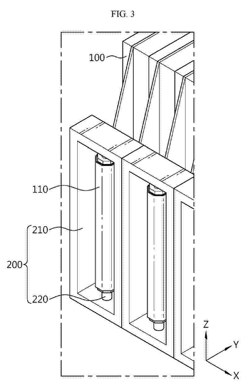
Resumen de: EP4765405A1
0001 A battery pack according to the present disclosure includes cylindrical secondary batteries provided in plurality; and pouch-type secondary batteries positioned between the plurality of cylindrical secondary batteries and having a curved surface corresponding to a side surface of the cylindrical secondary battery on a side facing the cylindrical secondary battery.
Resumen de: EP4765221A1
The present invention relates to a dry electrode including a current collector, and an electrode material mixture film disposed on the current collector, wherein the electrode material mixture film includes an electrode active material and a fibrillizable binder, a ratio (IB/IA) of a C3H7+ peak intensity (IB) to a C2H3O+ peak intensity (IA), which is measured on a surface of the current collector by Time-of-Flight secondary ion mass spectrometry (ToF-SIMS), is 1.3 or less, and a ratio of carbon content at an interface of the current collector to carbon content in the electrode material mixture film, which is measured by scanning electron microscope-energy dispersive X-ray spectroscopy, is 1.08 or more.
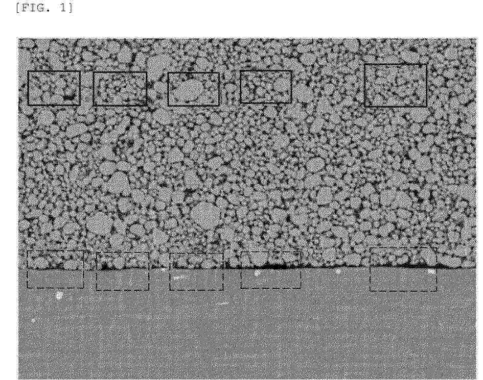
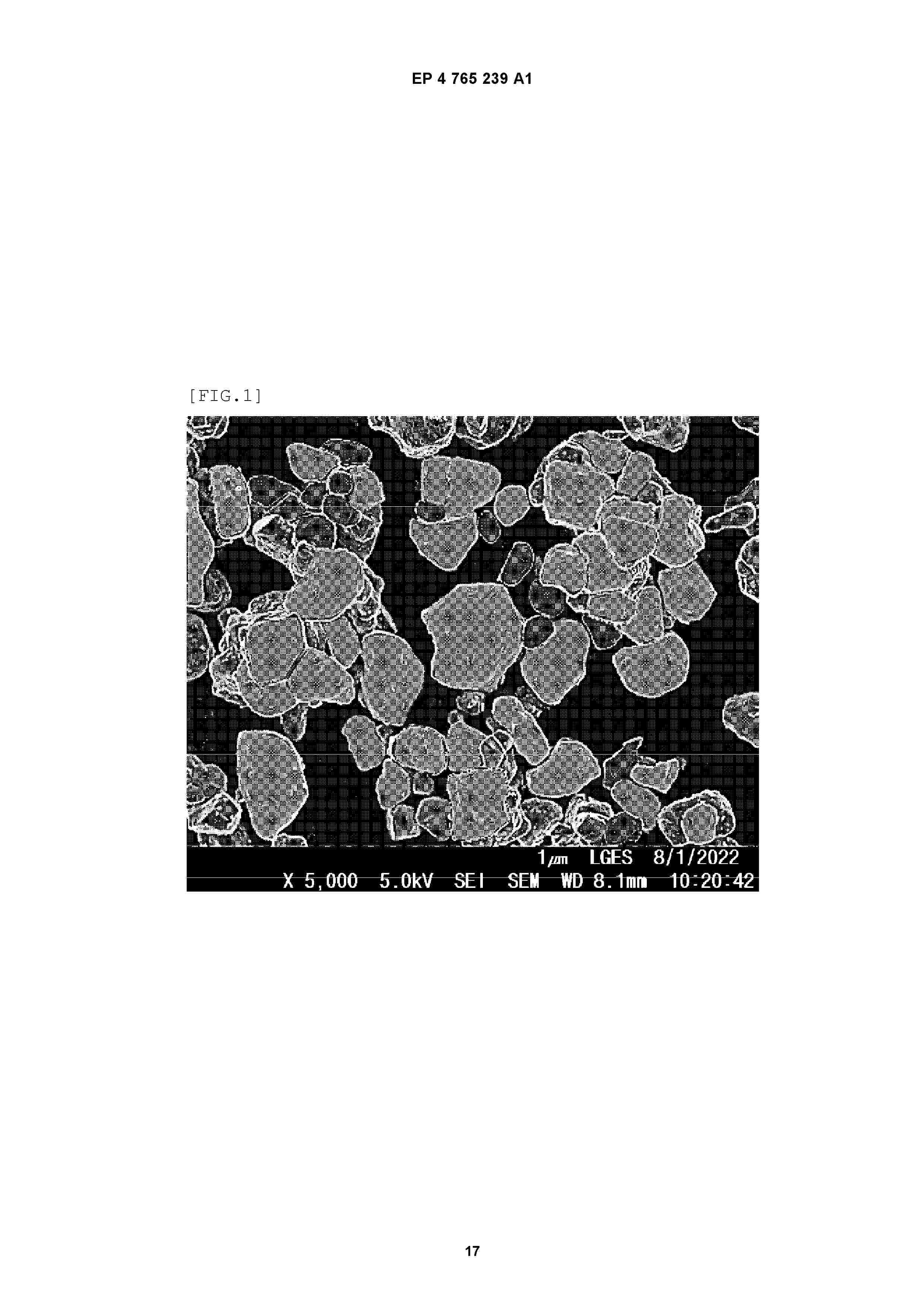
Resumen de: EP4765239A1
The present invention relates to a positive electrode active material including a lithium composite transition metal oxide in the form of a single particle composed of one nodule or a pseudo-single particle, which is a composite of 30 or fewer nodules, and a coating layer including a first coating layer formed on the surface of the lithium composite transition metal oxide and a second coating layer formed on the surface of the first coating layer, wherein the lithium composite transition metal oxide has a roundness, which is defined by Equation 1 below, of 0.50 to 0.68, and the second coating layer contains boron, wherein the boron is included in a weight of 300 ppm to 2400 ppm based on the total weight of the positive electrode active material. Roundness=4×Area/π×R2In Equation 1 above, R denotes the length of a major axis passing through the center of the lithium composite transition metal oxide, and Area denotes an actual area of the lithium composite transition metal oxide.
Resumen de: EP4765224A1
0001 The present invention relates to a positive electrode for a sodium secondary battery, the positive electrode including a current collector, a first positive electrode active material layer disposed on the current collector, and a second positive electrode active material layer disposed on the first positive electrode active material layer, wherein the first positive electrode active material layer includes a first positive electrode active material, and the second positive electrode active material layer includes a second positive electrode active material, wherein the first positive electrode active material includes sodium composite transition metal oxide particles having an O3 octahedral crystal structure, and the second positive electrode active material includes sodium composite transition metal oxide particles having a P2 orthorhombic crystal structure, wherein a ratio of the average particle diameter (D<50>) between the first positive electrode active material and the second positive electrode active material is 2:1 to 3:1.
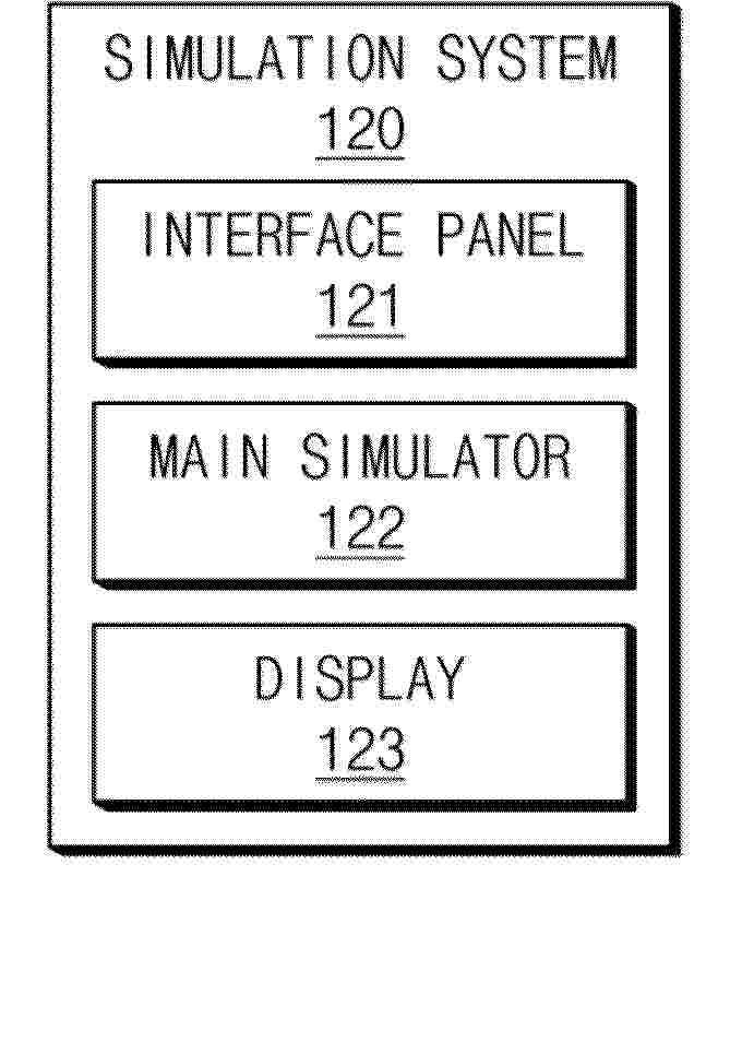
Resumen de: EP4765072A1
According to some embodiments, a simulation system includes an interface panel configured to receive a manipulation input from an operator, a main simulator configured to load a training content which reproduces an end of line (EOL) process for manufacturing a cylindrical battery based on the manipulation input and provide the training content to the operator through interaction with the operator, and a display configured to display a specific image according to specific processes of the EOL process.
Resumen de: EP4765276A1
According to an embodiment of the present disclosure, provided is a bipolar battery comprising:a bipolar assembly comprising a stacked body containing a bipolar electrode and a separator, and a gel electrolyte impregnated throughout the stacked body; and a battery case,and not comprising an interfacial gap at the interface between the bipolar electrode and the separator,wherein the gel electrolyte voids within the stacked body are 5% or less of the total volume capable of gel electrolyte impregnation.
Resumen de: EP4765275A1
0001 An apparatus for manufacturing a battery cell according to an embodiment of the present disclosure includes a vacuum chamber in which a semi-finished battery cell is placed, the semi-finished battery cell including an accommodation portion accommodating an electrolyte solution and an electrode assembly, and a gas pocket portion connected to the accommodation portion and located higher than the accommodation portion; a piercing unit configured to form a degassing hole in the gas pocket portion by piercing; a sealing tool configured to form a temporary sealing portion across between the degassing hole and the accommodation portion, and form a sealing area including the temporary sealing portion while the sealing tool moves up in a state of being in contact with the gas pocket portion; a cutting unit configured to cut off a portion of an upper part of the gas pocket portion to form an opening after the temporary sealing portion is formed; and a spray unit configured to spray gas into the opening.
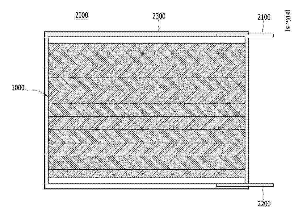
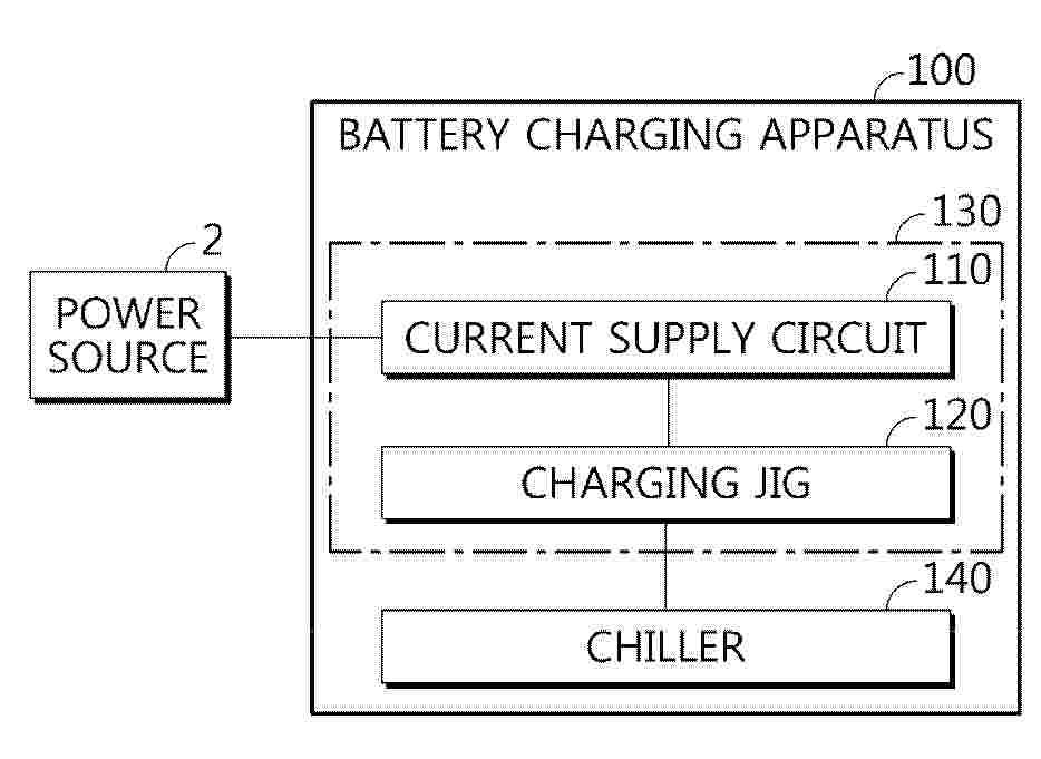
Resumen de: EP4765566A1
A battery charging apparatus according to the present disclosure includes a current supply circuit configured to supply charging current through a plurality of conducting wires that each corresponds to respective one of the plurality of batteries; and a charging jig configured to support the plurality of batteries and provide the charging current supplied through the plurality of conducting wires to the plurality of batteries, wherein the charging jig includes a plurality of connection pins electrically connecting the plurality of conducting wires to the first electrode terminals of the plurality of batteries; a conductive plate that is in common contact with the second electrode terminals of the plurality of batteries to allow the second electrode terminals to have the same potential; and a cooling structure having a cooling channel through which a cooling material moves and configured to cool the conductive plate.
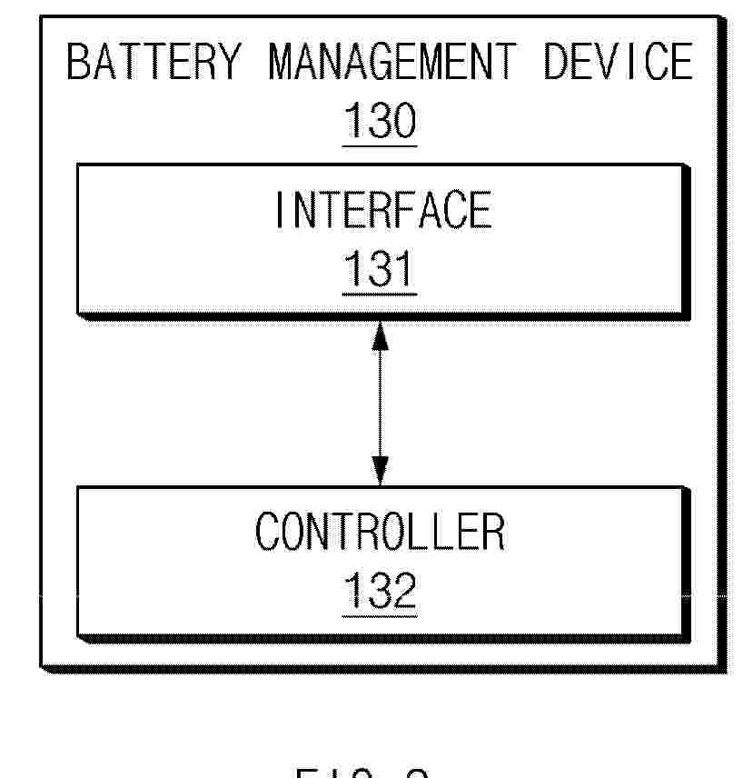
Resumen de: EP4764529A1
0001 According to some embodiments, a battery management device includes an interface configured to acquire battery data of a battery and a controller configured to calculate a first state of health (SOH) value of the battery based on the battery data, calculate a first SOH correction value for the first SOH value using a regression equation that calculates an SOH correction value based on error factors causing an error in the first SOH value, and calculate a second SOH value by applying the first SOH correction value to the first SOH value.
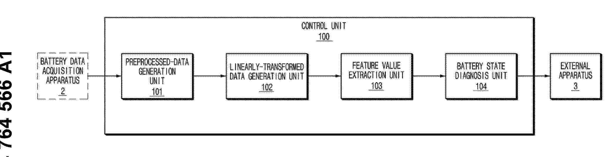
Resumen de: EP4764566A1
An apparatus for diagnosing a battery includes a communication interface for receiving battery data obtained by applying a current signal to a battery module, and at least one processor for performing error correction to correct an influence of a sensing line related to a structure of the battery module and generating preprocessed data from the battery data, extracting a feature value based on the preprocessed data, and diagnosing whether the battery module is abnormal based on a plurality of feature values extracted at different time zones.
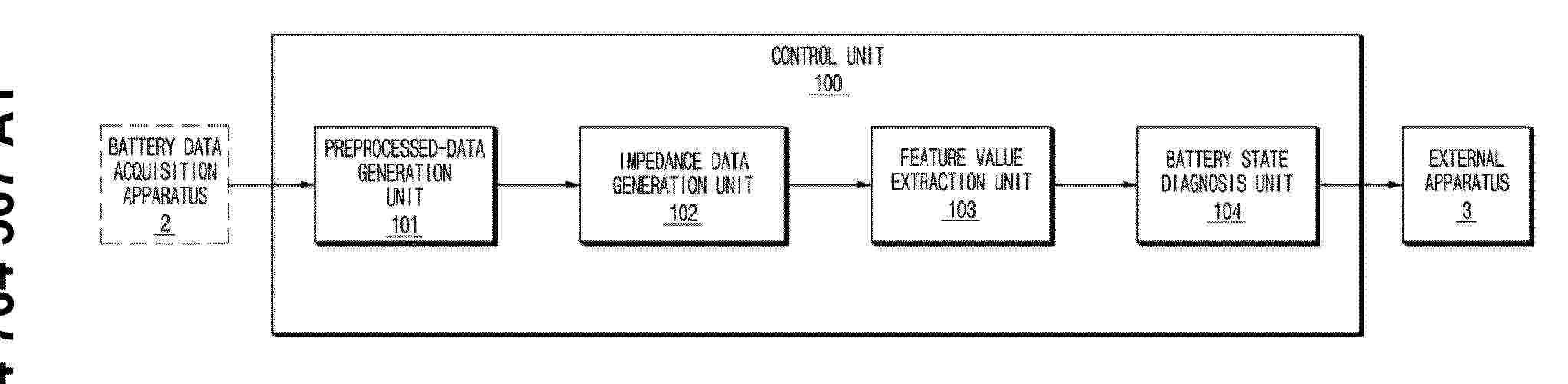
Resumen de: EP4764567A1
0001 An apparatus for diagnosing battery disclosed in this document includes a communication interface configured to receive battery data acquired by applying a current signal to a battery pack, and at least one processor configured to remove noise from the battery data to generate preprocessed data, apply a fast Fourier transform to the preprocessed data and acquire impedance data, and extract a feature value in which an influence of a sensing line is corrected from the impedance data and diagnose whether the battery pack is abnormal.
Resumen de: EP4765416A1
Disclosed is a battery module, and a battery pack and a vehicle including the same. The battery module includes a battery cell stack in which a plurality of battery cells are stacked; a module case in which the battery cell stack is accommodated; and a flame suppression pad arranged between the plurality of battery cells within the module case, and the module case has a rupture portion formed to be ruptured by gas.
Resumen de: EP4765395A1
0001 Embodiments provide a battery pack. The battery pack includes a pack housing with a base plate and a plurality of battery cell assemblies on the base plate, in which each of the plurality of battery cell assemblies includes a plurality of battery cells arranged in a first direction, a first side beam and a second side beam spaced apart from each other with the plurality of battery cells therebetween, and a first fireproof structure coupled to the first side beam, the first fireproof structure includes a first fire-resistant sheet and a first fire-resistant adhesive layer applied to the first fire-resistant sheet, and the first fire-resistant sheet and the first fire-resistant adhesive layer include different materials.
Nº publicación: EP4763404A1 24/06/2026
Solicitante:
LG ENERGY SOLUTION LTD [KR]
LG Energy Solution, Ltd.
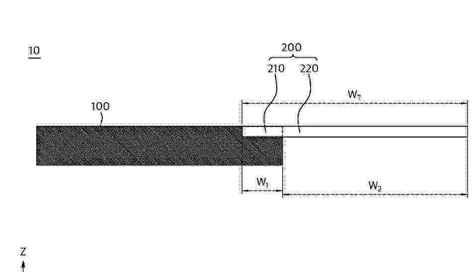
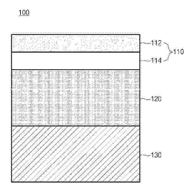
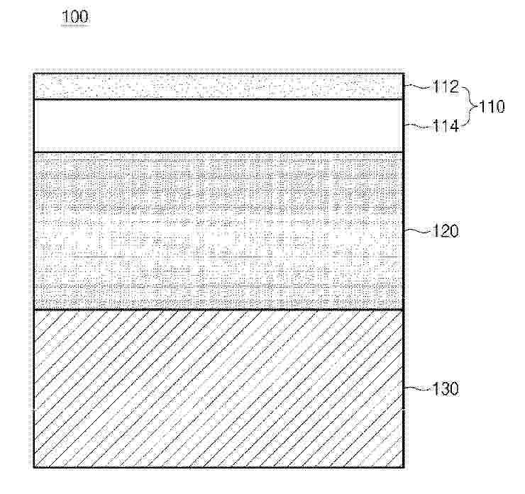
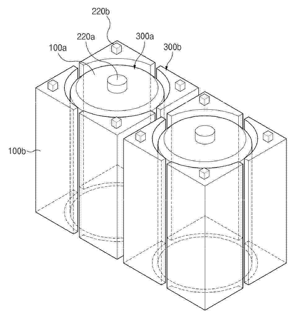
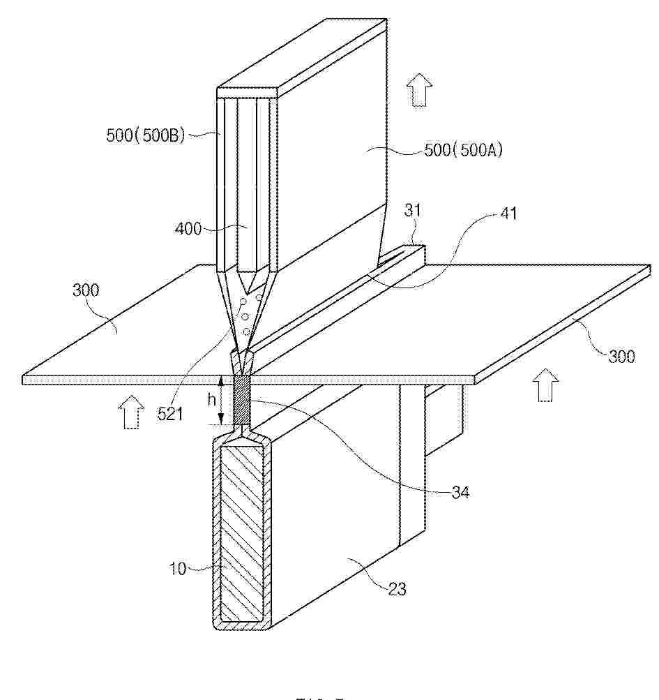
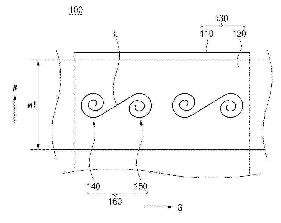
Resumen de: EP4763404A1
0001 The present disclosure relates to a welding method, a welded product, and a battery module, and the welding method according to the present disclosure includes a positioning process in which multiple base materials are positioned in overlapping with each other; and a welding process in which the multiple base materials are welded together to form a predetermined welding pattern, wherein the welding process welds the welding pattern in a form in which a plurality of spiral patterns are connected without overlapping.
 BOPI
BOPI
 Sede Electrónica