Si deseas distinguir tus productos, servicios o ambos de los de otra empresa, es posible que necesites una marca o nombre comercial. Descubre qué son, en qué consiste su procedimiento de registro y qué implica.

Información sobre los plazos de presentación de solicitudes de transformación de marcas de la Unión Europea en marca nacional española. Más información


Si tienes un nuevo dispositivo, producto o procedimiento que resuelva un problema técnico o tenga una ventaja práctica, existen distintas formas de protegerlo en España y en otros países. Descubre cómo hacerlo.

¿Tu innovación reside en la estética, la ornamentación o la apariencia de tu producto? Protégela mediante un diseño industrial. Descubre qué derechos confiere el registro y cómo realizar la tramitación.

Las indicaciones geográficas protegen el nombre de un producto originario de una zona geográfica, a la cual le debe una determinada calidad, reputación u otra característica. Descubre qué son, en qué consiste su procedimiento de registro y qué beneficios conceden.

Las patentes publicadas en todo el mundo son una valiosa fuente de información científica, técnica y comercial.

Si eres emprendedor/a o una empresa y quieres potenciar y mejorar la rentabilidad de tu negocio protegiendo de forma adecuada los activos intangibles de tu organización, en este espacio encontrarás lo necesario.


 1603
resultados
1603
resultados
 Última actualización
24/06/2026 [07:18:00]
Última actualización
24/06/2026 [07:18:00]


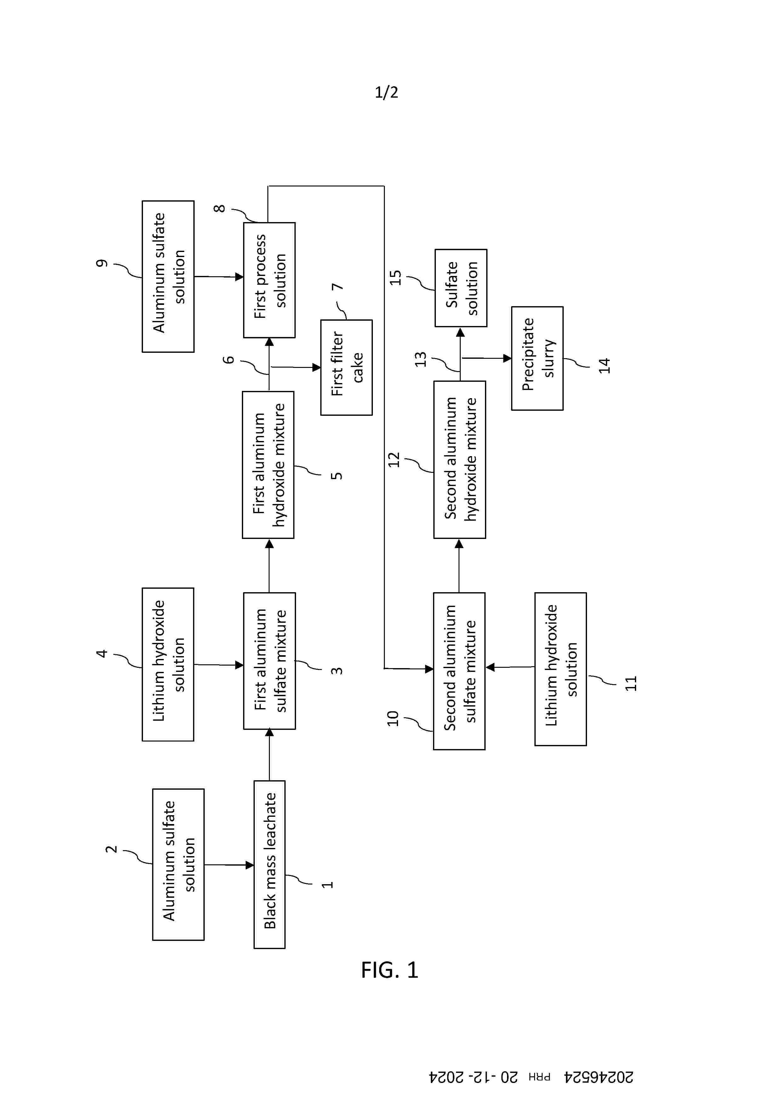
Resumen de: FI20246524A1
According to an example aspect, there is provided a method for precipitating impurities from a black mass leachate, comprising steps of: 1a) providing a black mass leachate (1) comprising at least one of nickel, cobalt and lithium, and impurities; 1b) mixing an aluminum sulfate solution (2) with the black mass leachate (1) to produce a first aluminum sulfate mixture (3); 1c) adding a lithium hydroxide solution (4) to the first aluminum sulfate mixture (3), to produce a first aluminum hydroxide mixture (5); 1d) filtrating (6) the first aluminum hydroxide mixture (5), to produce a first filter cake (7) comprising impurities and a first process solution (8); 2a) mixing an aluminum sulfate solution (9) with the first process solution (8), to produce a second aluminum sulfate mixture (10); 2b) adding a lithium hydroxide solution (11) to the second aluminum sulfate mixture (10), to produce a second aluminum hydroxide mixture (12); 2c) filtrating (13) the second aluminum hydroxide mixture (12), to produce a precipitate slurry comprising residual impurities and a sulfate solution (15).

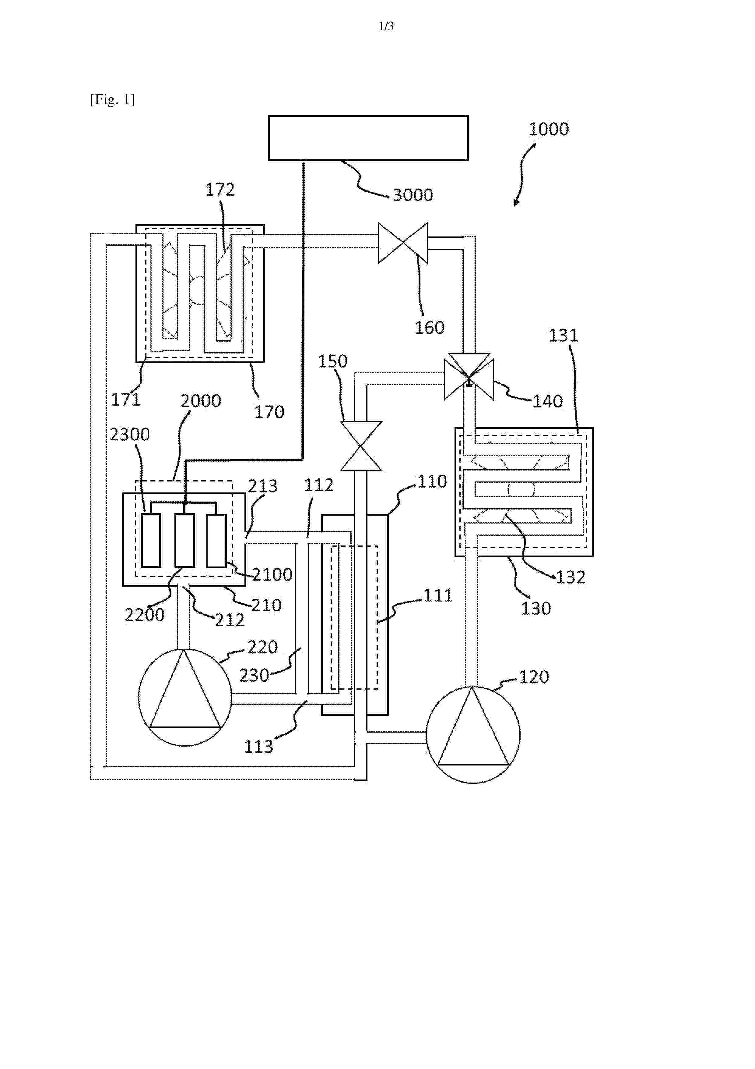
Resumen de: FR3170106A1
Procédé de refroidissement d’une batterie (2000) d’un moteur (3000) d’un véhicule automobile comprenant un circuit frigorifique (100) incluant un premier évaporateur (110), un circuit d’huile diélectrique (200) comprenant un réservoir (210) contenant une huile diélectrique et des cellules (2100, 2200, 2300) de la batterie (2000) baignant dans l’huile diélectrique, le procédé étant caractérisé en ce qu’il comprend : Une circulation d’un fluide frigorigène par le circuit frigorifique (100) comprenant une évaporation du fluide frigorigène dans le premier évaporateur (110),Une circulation de l’huile diélectrique par le circuit d’huile diélectrique (200), comprenant :Une circulation de l’huile diélectrique dans le réservoir (210),Une circulation de l’huile diélectrique dans le premier évaporateur (110), comprenant un premier échange de chaleur, mis en œuvre par un échangeur de chaleur (111) du premier évaporateur (110), au cours de l’évaporation du fluide frigorigène, en prenant de l’énergie à l’huile diélectrique. Figure pour l’abrégé : figure 2
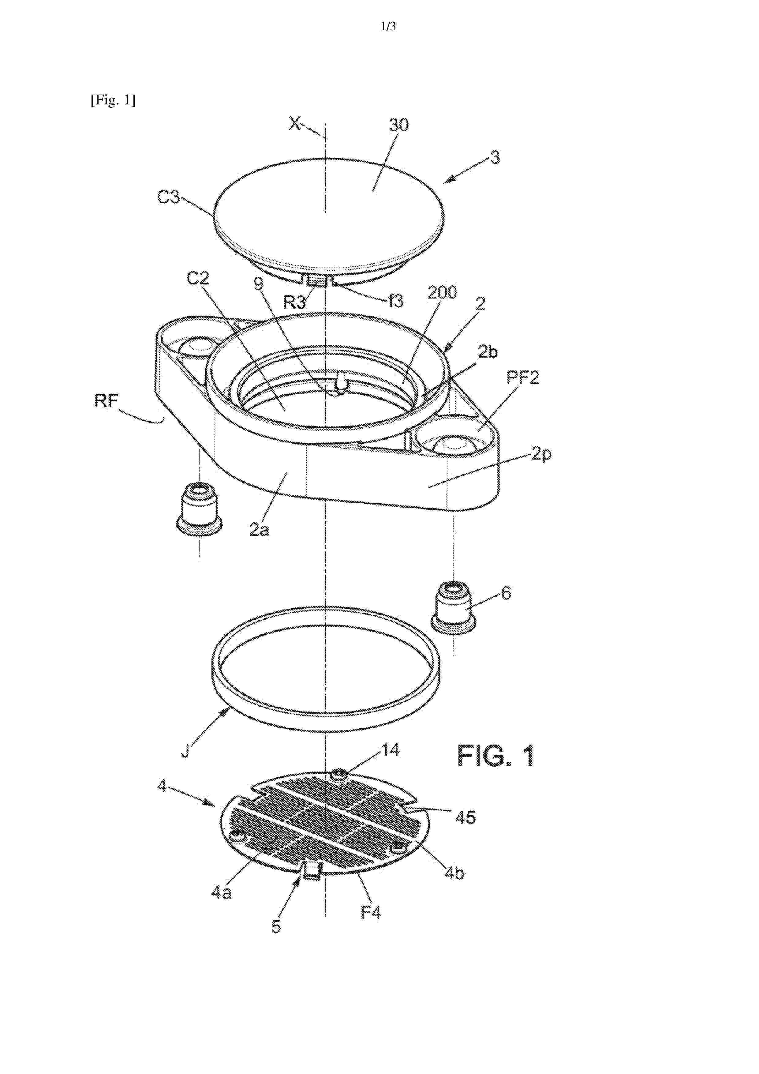
Resumen de: FR3170104A1
L’agencement (1) de ventilation pour boîtier de batterie inclut un corps (2) de montage, recouvrant par le dessus une ouverture du boîtier et un pourtour d’ouverture défini par une paroi (P) du boîtier, un canal étant prévu dans le corps en s’étendant jusqu’à un capot (3). Le canal guide un échappement gazeux (FG) provenant de l’intérieur du boîtier et le capot peut s’éjecter en cas de forte surpression. Une grille ou composant protecteur (4), typiquement métallique et ainsi thermiquement résistante, assure une protection anti-feu en se plaçant sous le corps (2) à l’opposé du capot. Le composant (4) inclut des attaches (5) s’engageant à l’intérieur du boîtier et obture le canal par le dessous tout en étant fixé indépendamment à la paroi (P) du boîtier, afin de conserver la protection même en cas de fonte du corps qui se raccorde à la paroi (P) en périphérie du composant. Figure de l’abrégé : Figure 2
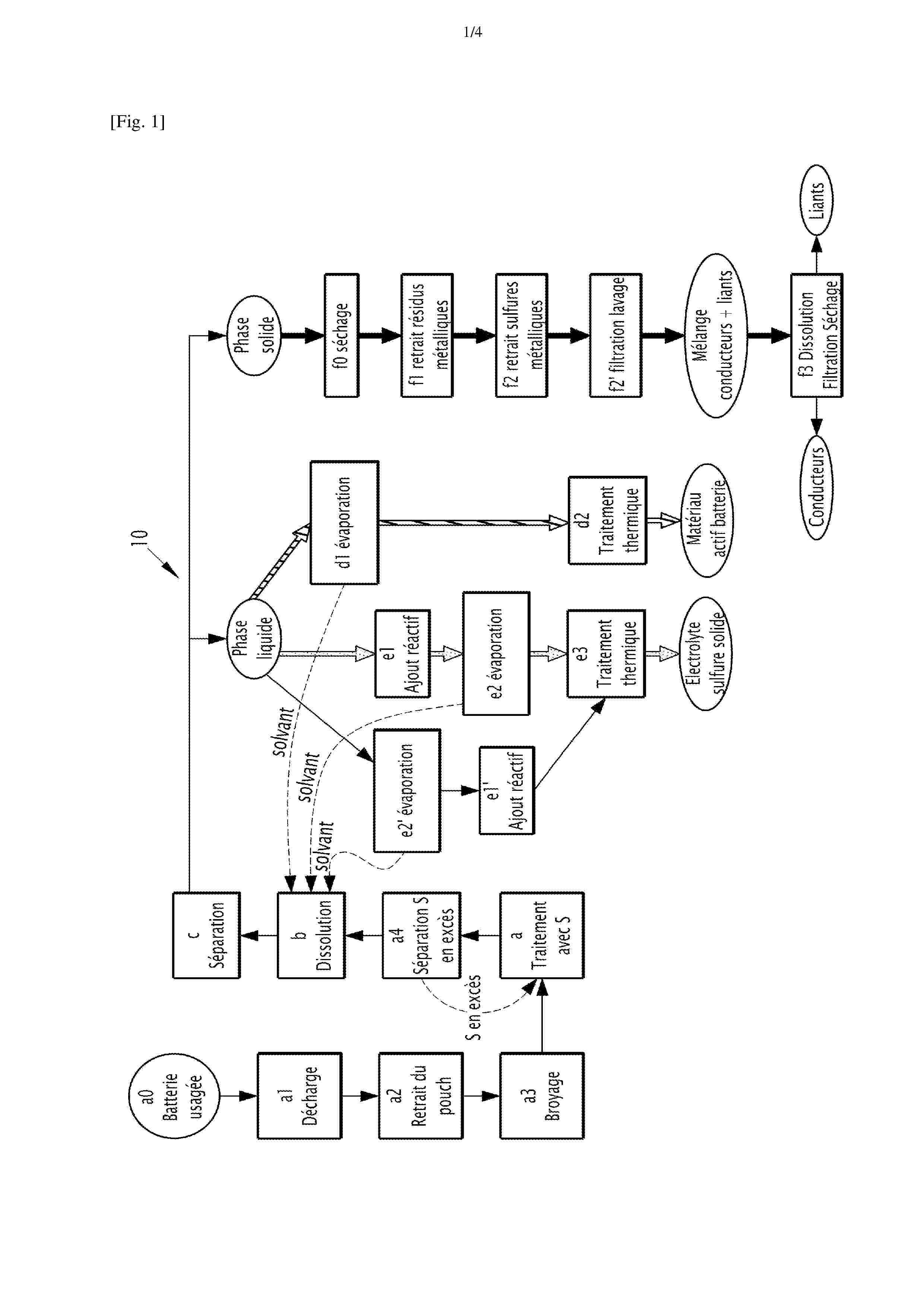
Resumen de: FR3170103A1
Procédé de recyclage d’éléments électrochimiques à électrode négative comprenant un métal alcalin La présente invention concerne un procédé de recyclage d’un élément électrochimique comprenant une électrode négative présentant une couche active négative comprenant un métal alcalin M sous forme métallique et/ou sous forme d’un alliage, M étant choisi parmi Li, Na et K, le procédé comprenant une étape a) de mise en contact du métal alcalin M avec du soufre élémentaire pour produire du M2S, l’étape a) de mise en contact étant mise en œuvre en l’absence de solvant. Figure pour l'abrégé : Figure 1
Resumen de: FR3170105A1
Système de refroidissement (3) d’une batterie (2) haute tension pour véhicule automobile (1), comprenant un premier réservoir (5) de liquide diélectrique (6), un deuxième réservoir (7) de liquide diélectrique (6), une pompe de circulation (8) du liquide diélectrique (6) et un échangeur de chaleur (9) apte à réguler la température dudit système de refroidissement (3). Le deuxième réservoir (7) est positionné dans un corps creux (10) du véhicule automobile (1) par des moyens de fixation (11) et est apte à adopter une position rétractée (PR) dans laquelle ledit deuxième réservoir (7) ne comprend pas de liquide diélectrique (6) et une position déployée (PD) dans laquelle ledit deuxième réservoir (7) comprend du liquide diélectrique (6). Figure pour l’abrégé : Fig 2
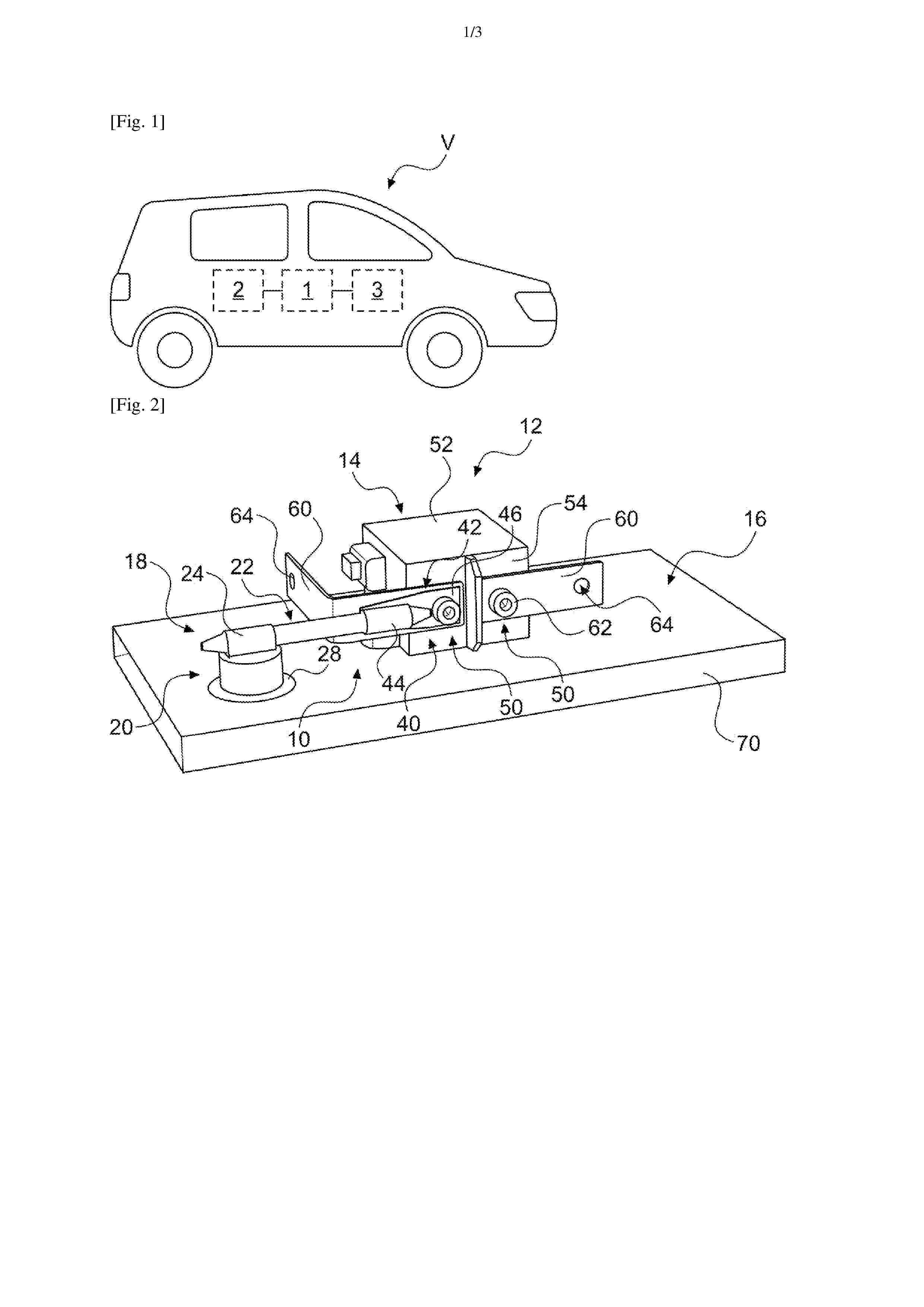
Resumen de: FR3169781A1
Dispositif de dissipation thermique, notamment pour véhicule automobile, ledit dispositif étant configuré pour un échange thermique entre, d’une part, une source chaude (12) comprenant un organe électrique (14), et, d’autre part, une source froide (16), ledit dispositif comprenant un premier organe d’interface thermique (18), destiné à être à un potentiel électrique sensiblement identique à un potentiel électrique dudit organe électrique (14), ledit premier organe d’interface thermique (18) étant configuré pour une conduction de chaleur provenant de la source chaude (12) en direction de la source froide (16), ledit dispositif comprenant en outre un premier boîtier (20) accueillant un fluide diélectrique, ledit premier boîtier étant configuré pour établir un échange thermique entre ledit premier organe d’interface thermique (18) et ladite source froide (16). Figure pour l’abrégé : Figure 2
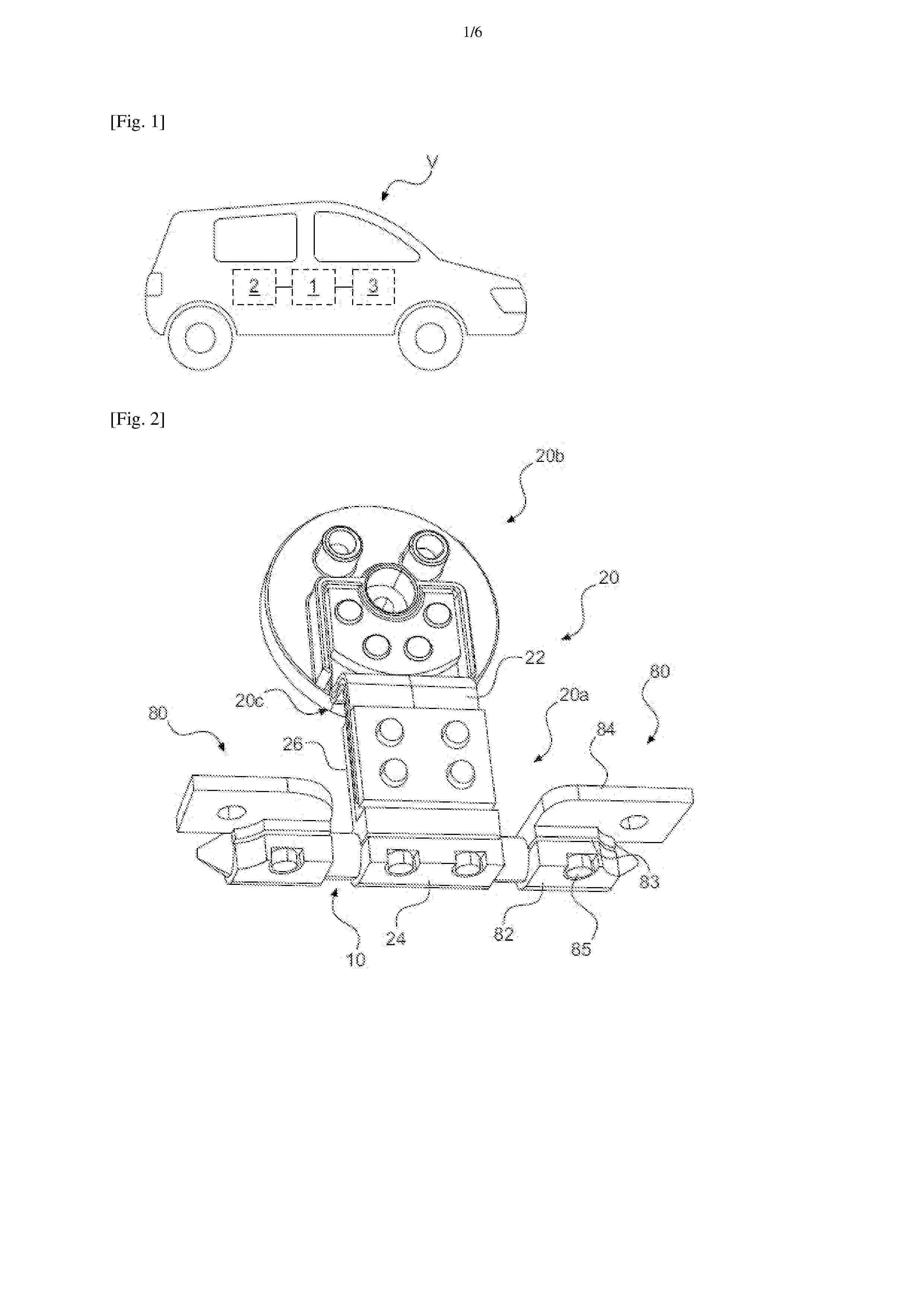
Resumen de: FR3169782A1
Dispositif de dissipation thermique, notamment pour véhicule automobile, ledit dispositif étant configuré pour un échange thermique entre, d’une part, une source chaude comprenant un organe électrique, et, d’autre part, une source froide, ledit dispositif comprenant en outre un premier organe d’interface thermique (20), ledit premier organe d’interface thermique comprenant une tête (20b) destinée à être en relation d’échange thermique avec l’une desdites sources chaude ou froide, ladite tête (20b) comprenant un matériau thermiquement conducteur et électriquement isolant (40) destiné à être en contact avec ladite source chaude ou froide en cause, ladite tête (20b) comprenant en outre une entretoise (44) de protection dudit matériau thermiquement conducteur et électriquement isolant (40). Figure pour l’abrégé : Figure 10
Resumen de: FR3169783A1
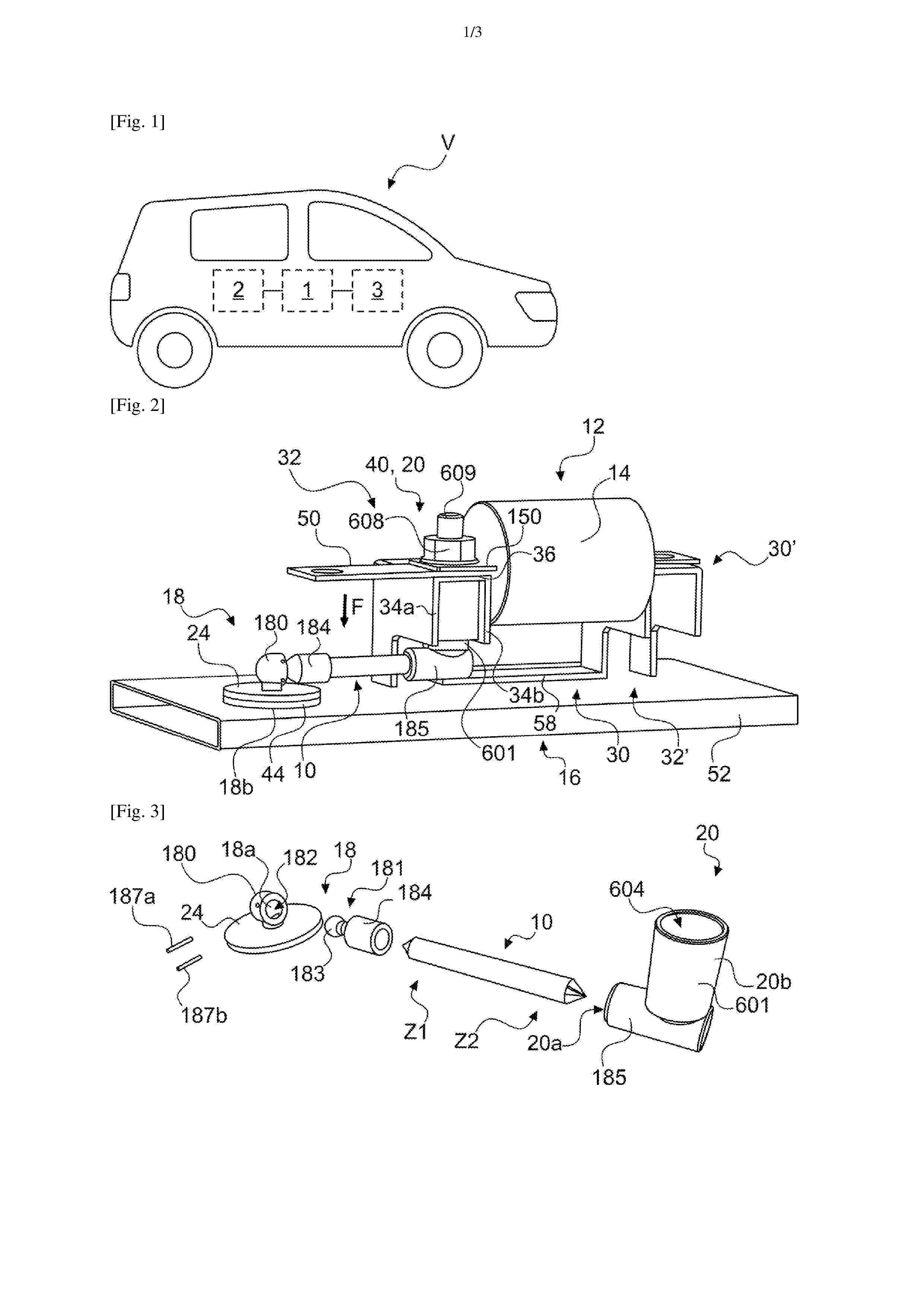
Dispositif de dissipation thermique (300, 300’), notamment pour véhicule automobile, ledit dispositif comprenant des caloducs (10) configurés pour un échange thermique entre, d’une part, des sources chaudes (12) comprenant respectivement un organe électrique (14), et, d’autre part, une source froide (16), ledit dispositif comprenant en outre un premier organe d’interface thermique (20), dit froid, en relation d’échange thermique avec lesdits caloducs (10) et destinée à être en relation d’échange thermique avec ladite source froide (16), de sorte à relier thermiquement chacune desdites sources chaudes (12) avec ladite source froide (16) et à relier électriquement entre elles lesdites sources chaudes (12) par l’intermédiaire desdits caloducs (10) et dudit organe d’interface thermique froid (20). Figure pour l’abrégé : Figure 3
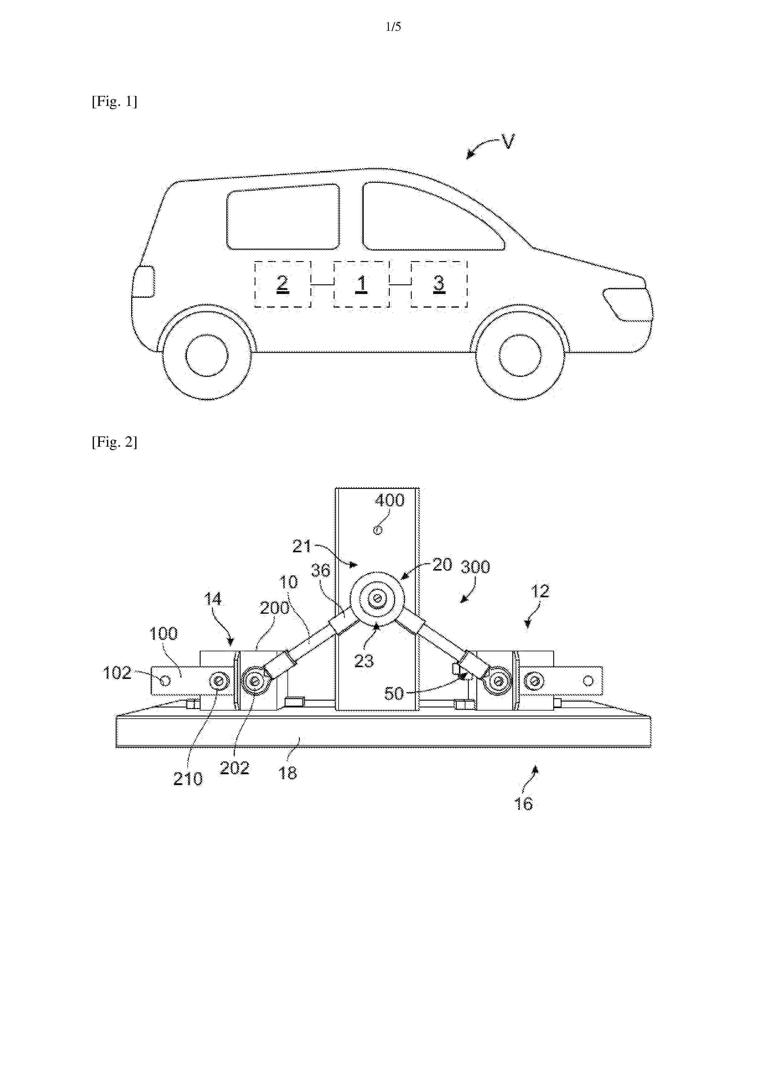
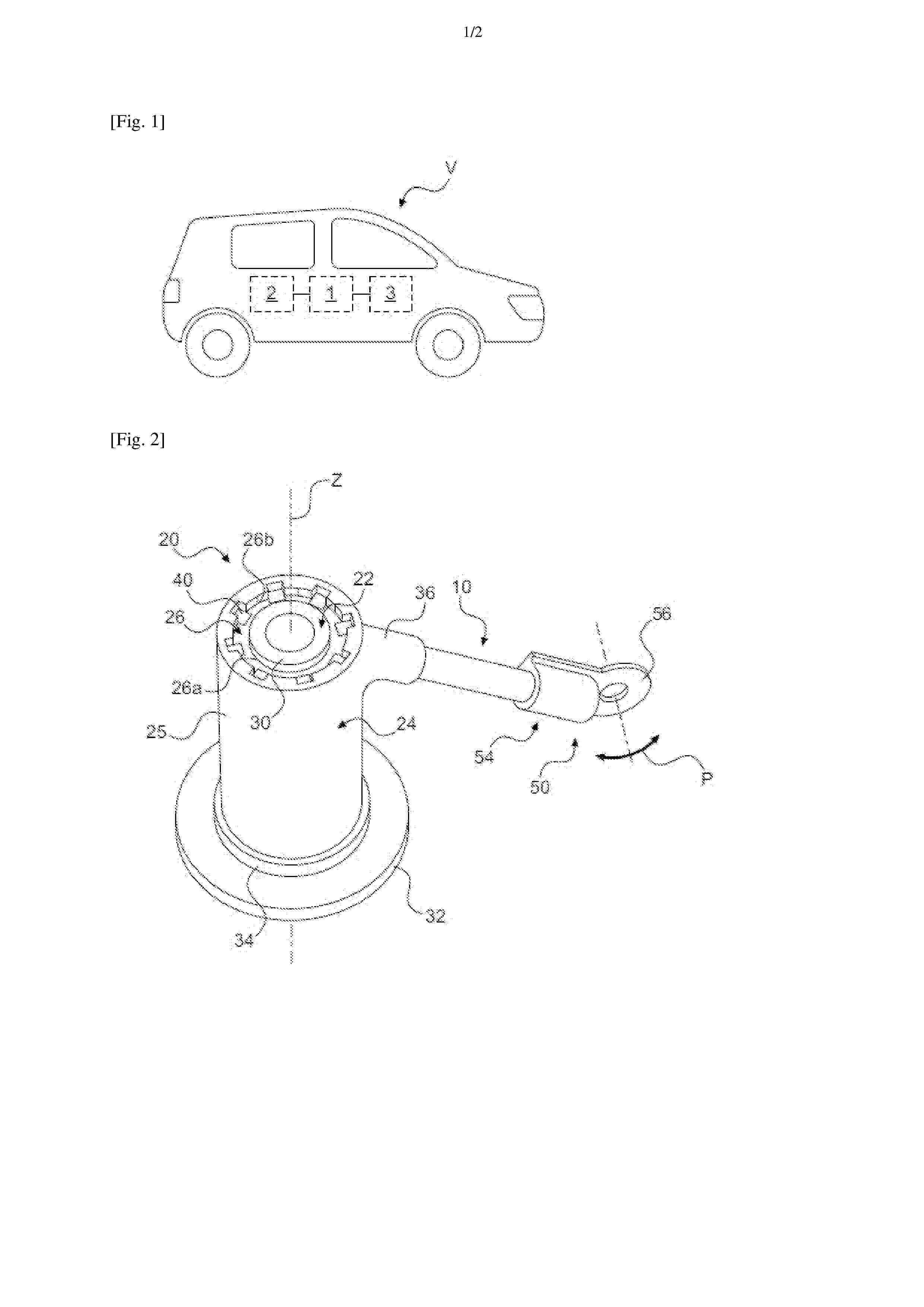
Resumen de: FR3169787A1
Dispositif de dissipation thermique, notamment pour véhicule automobile, ledit dispositif comprenant un caloduc (10) configuré pour un échange thermique entre, d’une part, une source chaude (12) comprenant un organe électrique (14), et, d’autre part, une source froide (16), ledit dispositif comprenant en outre : - un premier organe d’interface thermique (50) en contact avec le caloduc (10) et destinée à être en relation d’échange thermique avec l’une desdites sources chaude ou froide (12, 16), - un deuxième organe d’interface thermique (20) en contact avec le caloduc (10) et destinés à être en relation d’échange thermique avec l’autre desdits sources chaude ou froide (12,16), ledit premier organe d’interface thermique (50) étant configuré pour être mobile en pivotement de sorte à permettre une orientation angulaire dudit caloduc (10). Figure pour l’abrégé : Figure 2
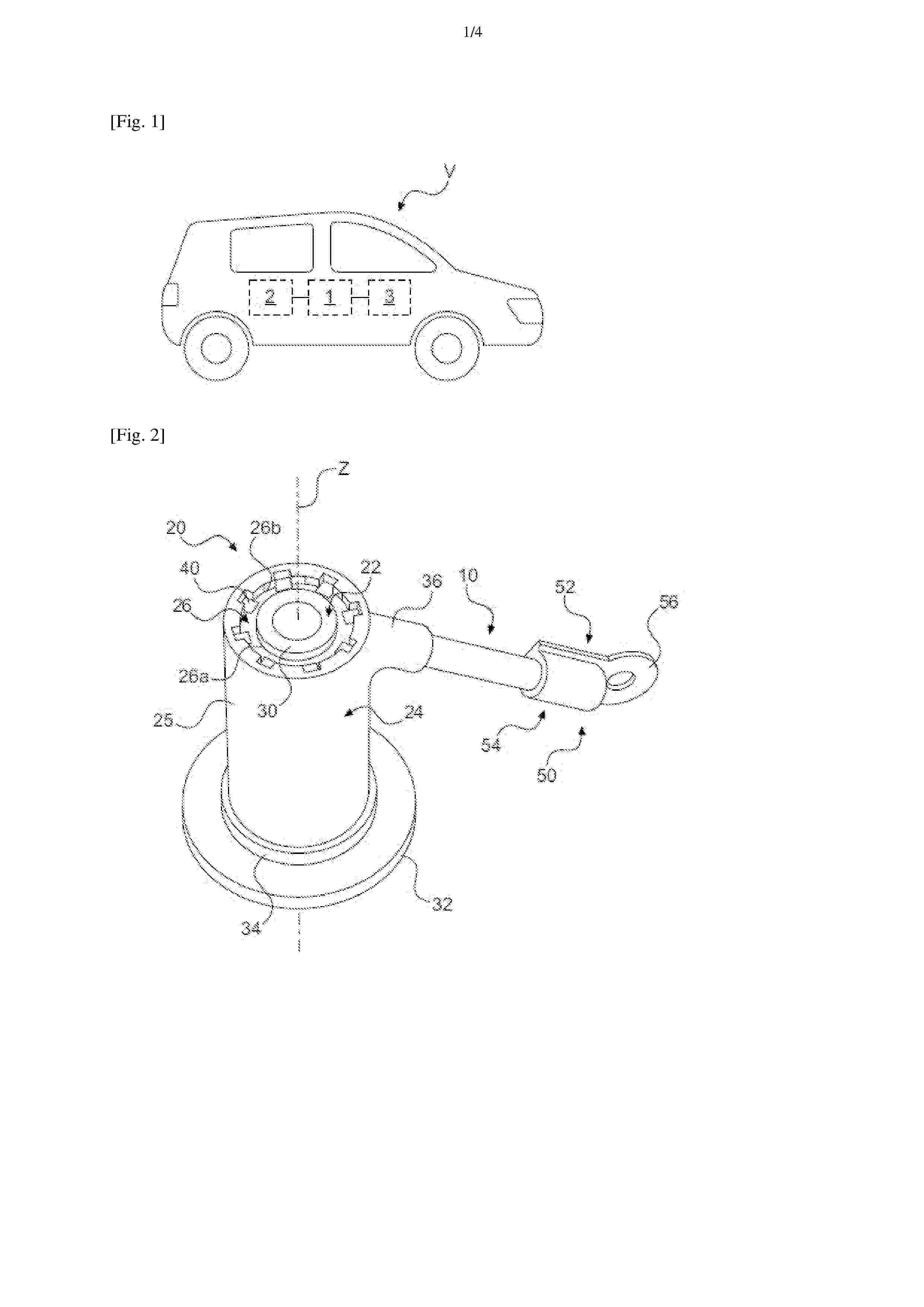
Resumen de: FR3169785A1
Dispositif de dissipation thermique, notamment pour véhicule automobile, ledit dispositif comprenant un ou plusieurs caloducs (10) configurés pour un échange thermique entre, d’une part, une ou plusieurs sources chaudes comprenant respectivement un organe électrique, et, d’autre part, une source froide , ledit dispositif comprenant en outre un premier organe d’interface thermique (20) en relation d’échange thermique avec le ou lesdits caloducs (10) et destinée à être en relation d’échange thermique avec l’une desdites sources chaude ou froide, ledit premier organe d’interface thermique (20) comprenant un pilier (22) de support, destiné à être en contact avec ladite source chaude ou froide, un carter (24), destiné à être en contact avec le ou lesdits caloducs (10), et un insert (26) électriquement isolant et formant un pont thermique entre ledit pilier (22) et ledit carter (24), ledit insert présentant une surface interne (26a) et une surface externe (26b) respectivement en contact avec une surface externe du pilier (22) et une surface interne du carter (24). Figure pour l’abrégé : Figure 2
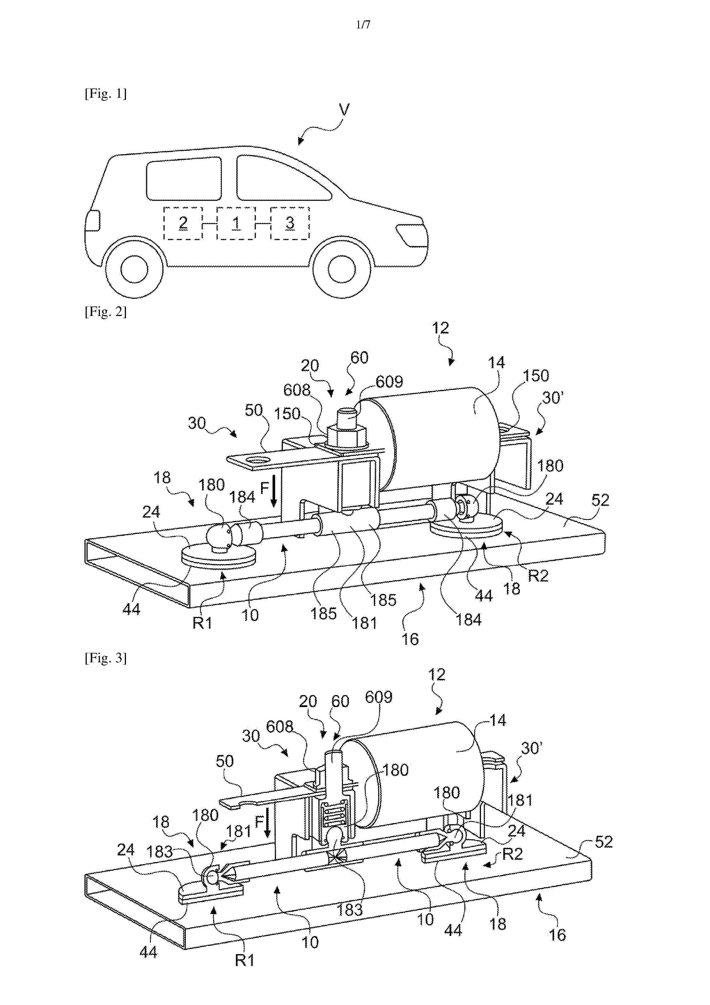
Resumen de: FR3170108A1
Dispositif de dissipation thermique, notamment pour véhicule automobile, ledit dispositif étant configuré pour une conduction de chaleur entre d’une part, une source chaude (12) comprenant un organe électrique (14), et, d’autre part, une source froide (16), ledit dispositif comprenant une organe d’interface thermique (20), dit chaud, configuré pour être en relation d’échange thermique avec ladite source chaude (12), et une pluralité d’organes d’interface thermique (18), dit froids, configurés pour être en relation d’échange thermique avec ladite source froide (16) selon une distribution spatiale répartie en plusieurs zones distinctes (R1, R2, …), ledit dispositif étant en outre configuré pour un échange thermique entre ledit organe d’interface thermique chaud (12) et lesdits organes d’interface thermique froids (18). Figure pour l’abrégé : Figure 2
Resumen de: FR3170115A1
La présente invention concerne une composition d’électrode comprenant au moins un liant et au moins une matière active pour la préparation d’une électrode de batterie sodium-ion.
Resumen de: FR3169984A1
Dispositif de dissipation thermique, notamment pour véhicule automobile, ledit dispositif comprenant un caloduc (10) configuré pour un échange thermique entre, d’une part, une source chaude (12) comprenant un organe électrique (14), et, d’autre part, une source froide (16), ledit dispositif comprenant en outre un ou plusieurs organes d’interface thermique (18, 20) configurés pour un échange thermique entre ledit caloduc (10) et l’une desdites sources chaude ou froide (12, 16) le ou lesdits organes d’interface thermique (18, 20) étant configurés pour autoriser une orientation angulaire dudit caloduc(10). Figure pour l’abrégé : Figure 7
Resumen de: FR3170124A1
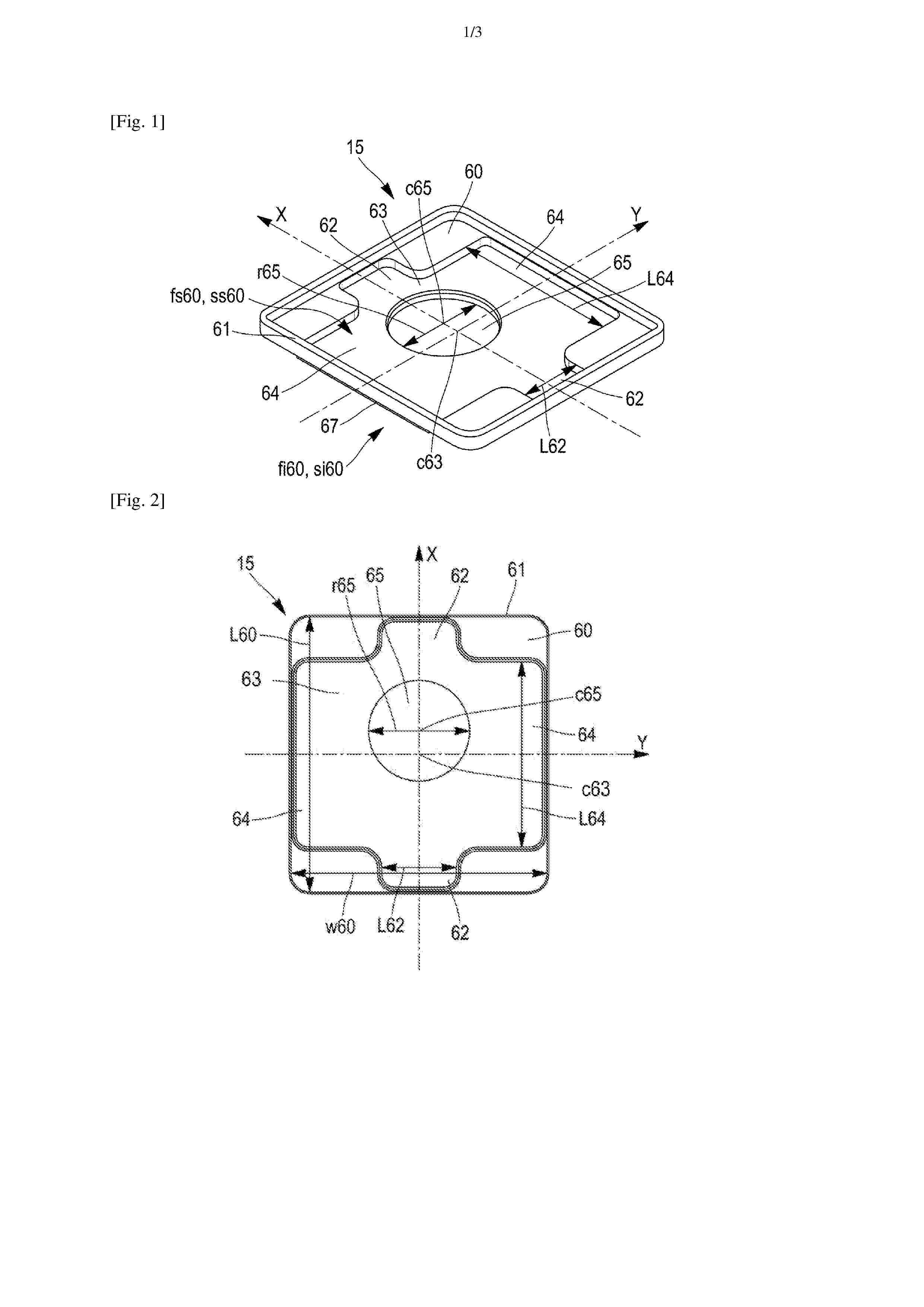
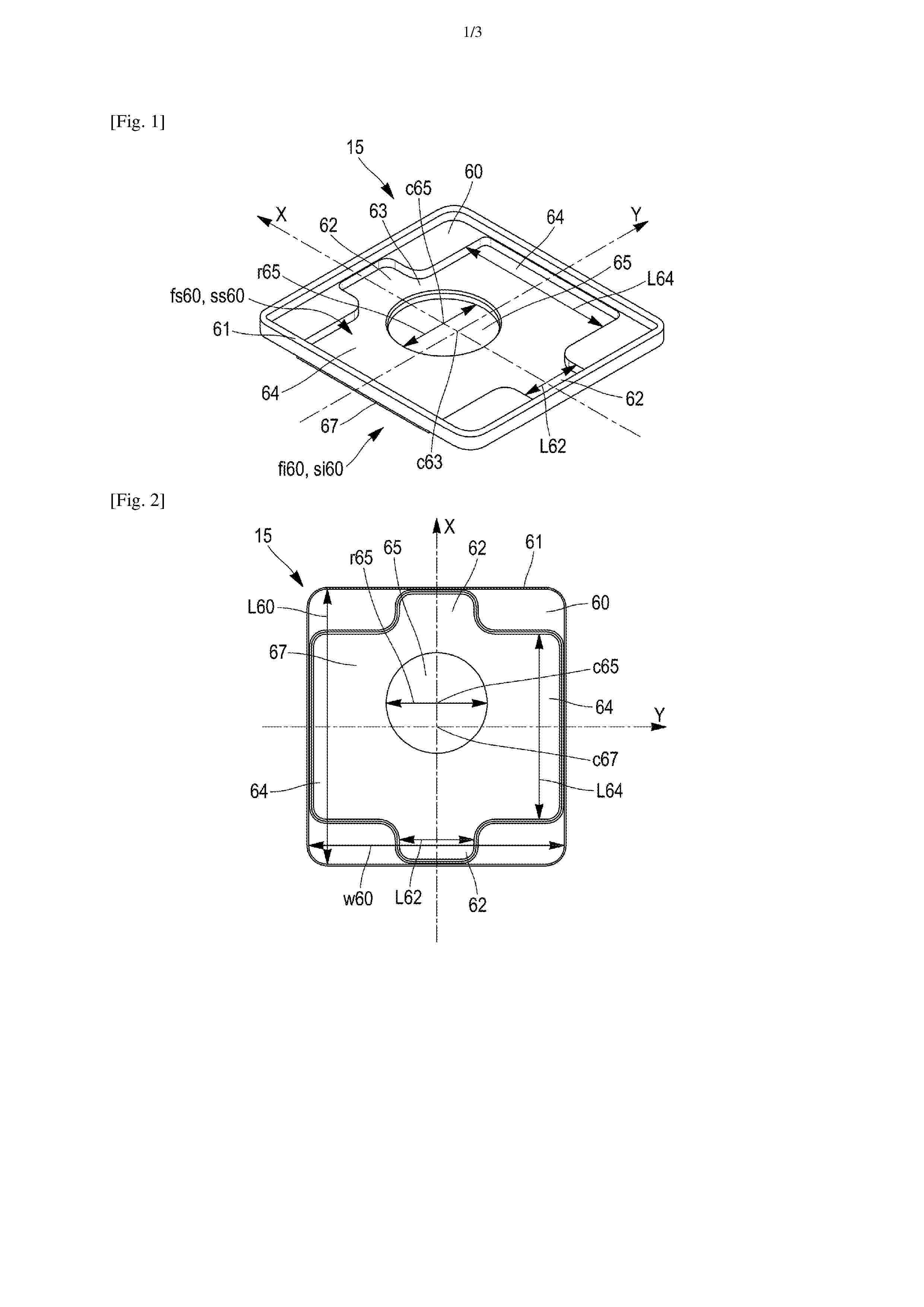
L’invention concerne un organe d’espacement (15) destiné à être interposé entre un couvercle (6) et un terminal (2, 3) d’une cellule de batterie (1) prismatique, ledit organe d’espacement (15) comprenant un corps principal (60) et présentant une face inférieure (fi60) destinée à venir en contact avec le couvercle (6), et une face supérieure (fs60) destinée à venir en contact avec le terminal (2, 3) ; l’organe d’espacement (15) comprenant sur sa face supérieure (fs60), une empreinte (63) en relief en forme de croix. L’invention concerne également un ensemble (5), et une cellule de batterie (1) comprenant un tel organe d’espacement (15). Figure 1
Resumen de: FR3170119A1
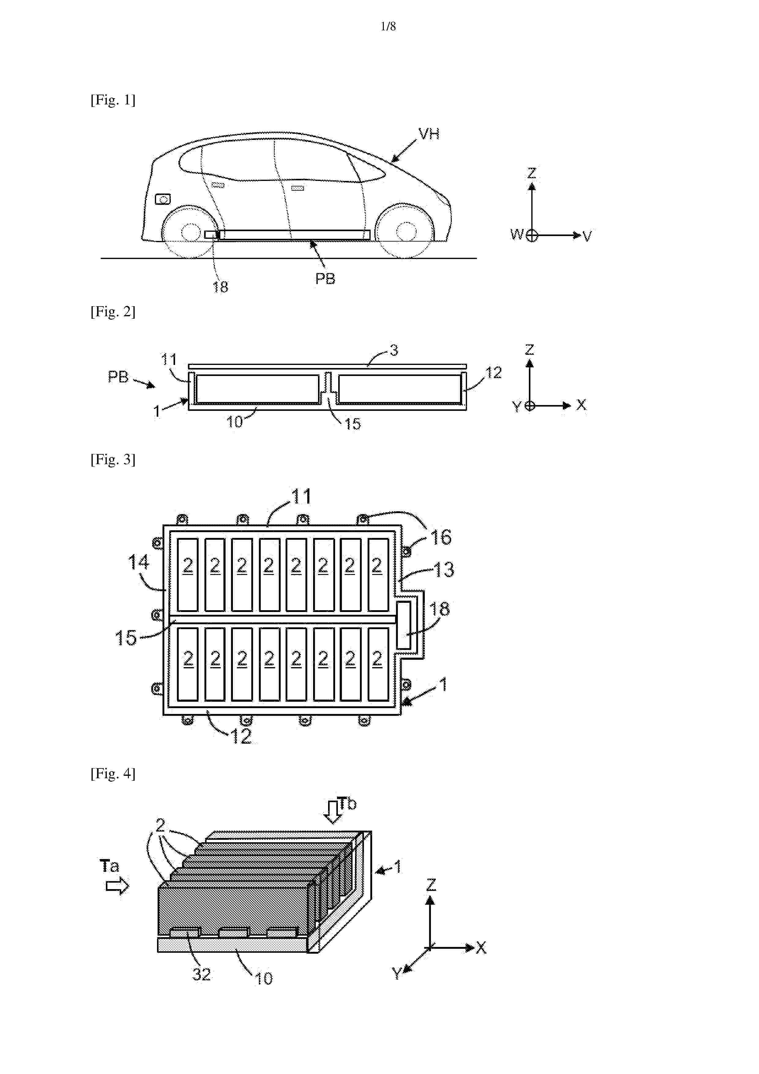
Pack batterie comprenant un bac batterie (1) comprenant un fond et des rebords montants, le fond étant équipé d’au moins un élément de guidage, tel qu’un rail ou des murets, étendu selon la direction longitudinale (X) et faisant saillie verticalement vers le haut à partir du fond, le pack batterie comprenant des modules de batterie électrique (2) amovibles, chaque module pouvant être individuellement inséré ou retiré du pack selon une direction d’insertion (T), chaque module inséré étant en interface de contact mécanique avec des éléments de guidage selon la direction transversale, avec un système de retenue agencé sur le bac pour maintenir le module en butée d’insertion le long de la direction d’insertion, et avec un système de connexion électrique configuré pour relier les bornes électriques du module à un collecteur formant un bus bar, l’établissement des contacts électriques étant réalisé de manière automatique par accouplement en fin d’insertion. Figure de l’abrégé : Fig. 2
Resumen de: FR3170118A1
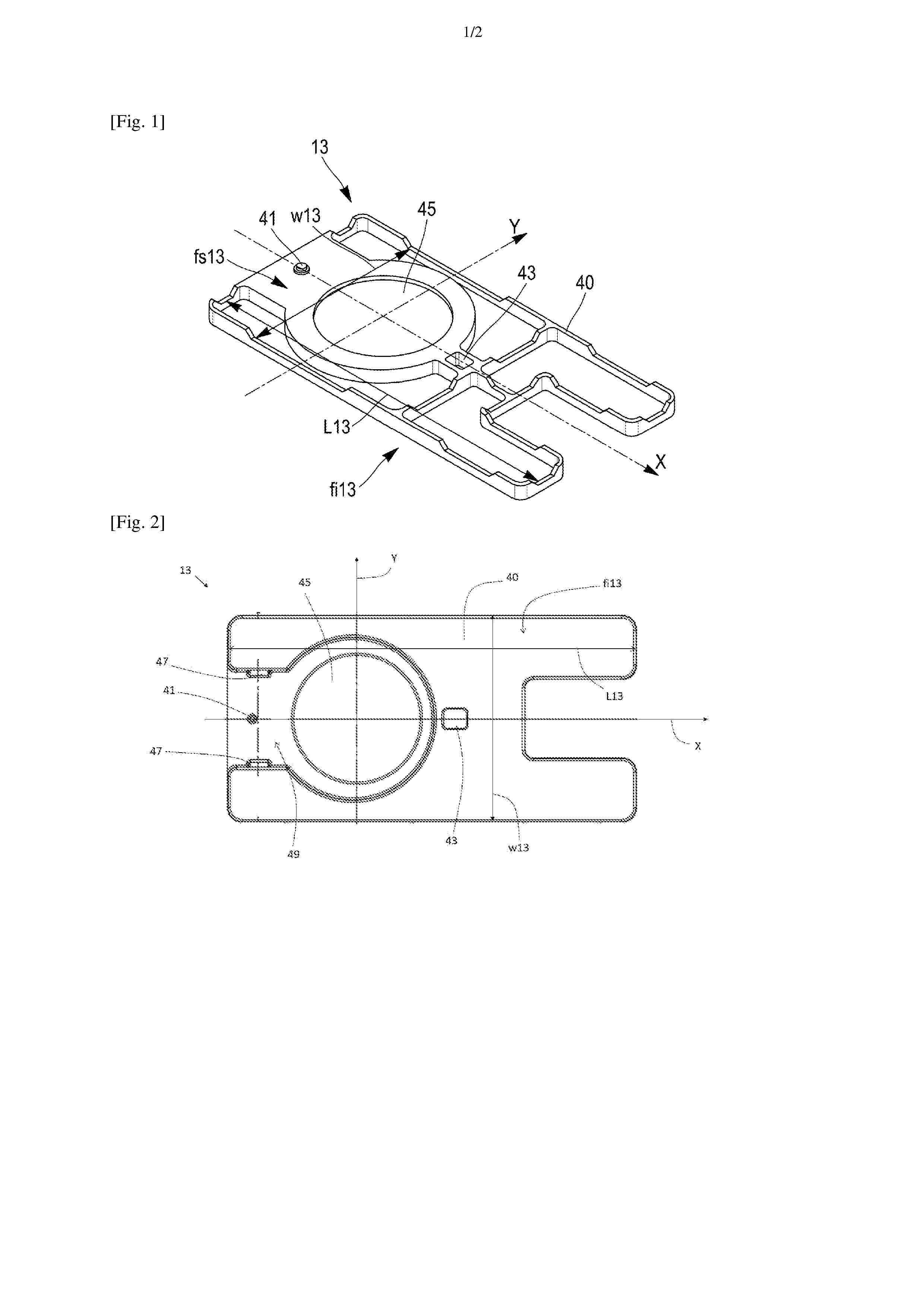
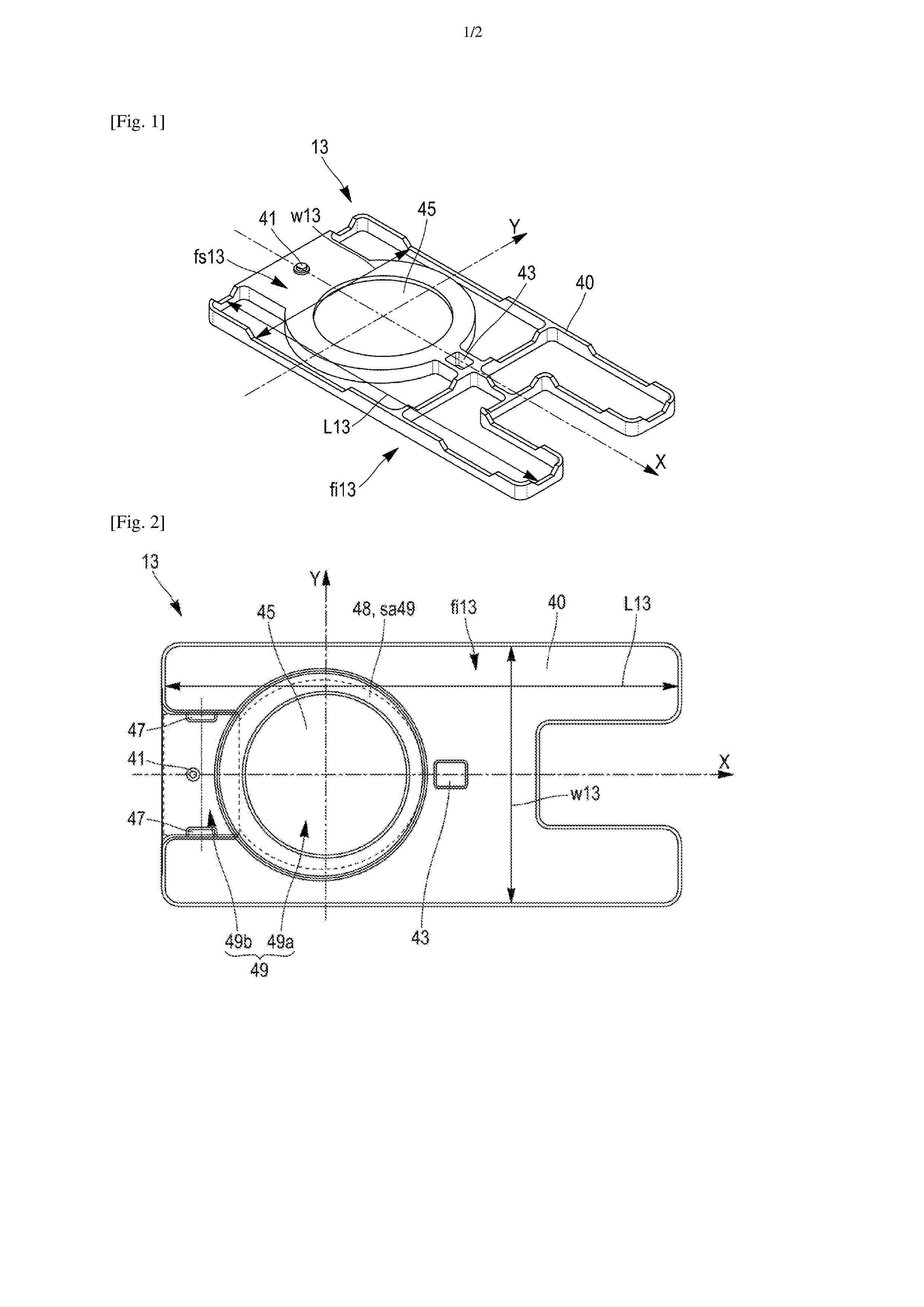
L’invention concerne un élément d’isolation (13) électrique destiné à être interposé entre un collecteur de courant (10) et un couvercle (6) d’une cellule de batterie (1) prismatique, ledit élément d’isolation (13) présentant une face inférieure (fi13) destinée à être tournée vers le collecteur de courant (10), et une face supérieure (fs13) destinée à venir en contact avec le couvercle (6) ; l’élément d’isolation (13) comprenant sur sa face supérieure (fs13), des éléments de positionnement (41, 43) en relief destinés à coopérer par complémentarité de forme avec des éléments complémentaires délimités par le couvercle (6) d’une manière bloquant une translation relative et une rotation relative entre l’élément d’isolation (13) et le couvercle (6). L’invention concerne également un ensemble (5) et une cellule de batterie (1) comprenant un tel élément d’isolation (13). Figure 1
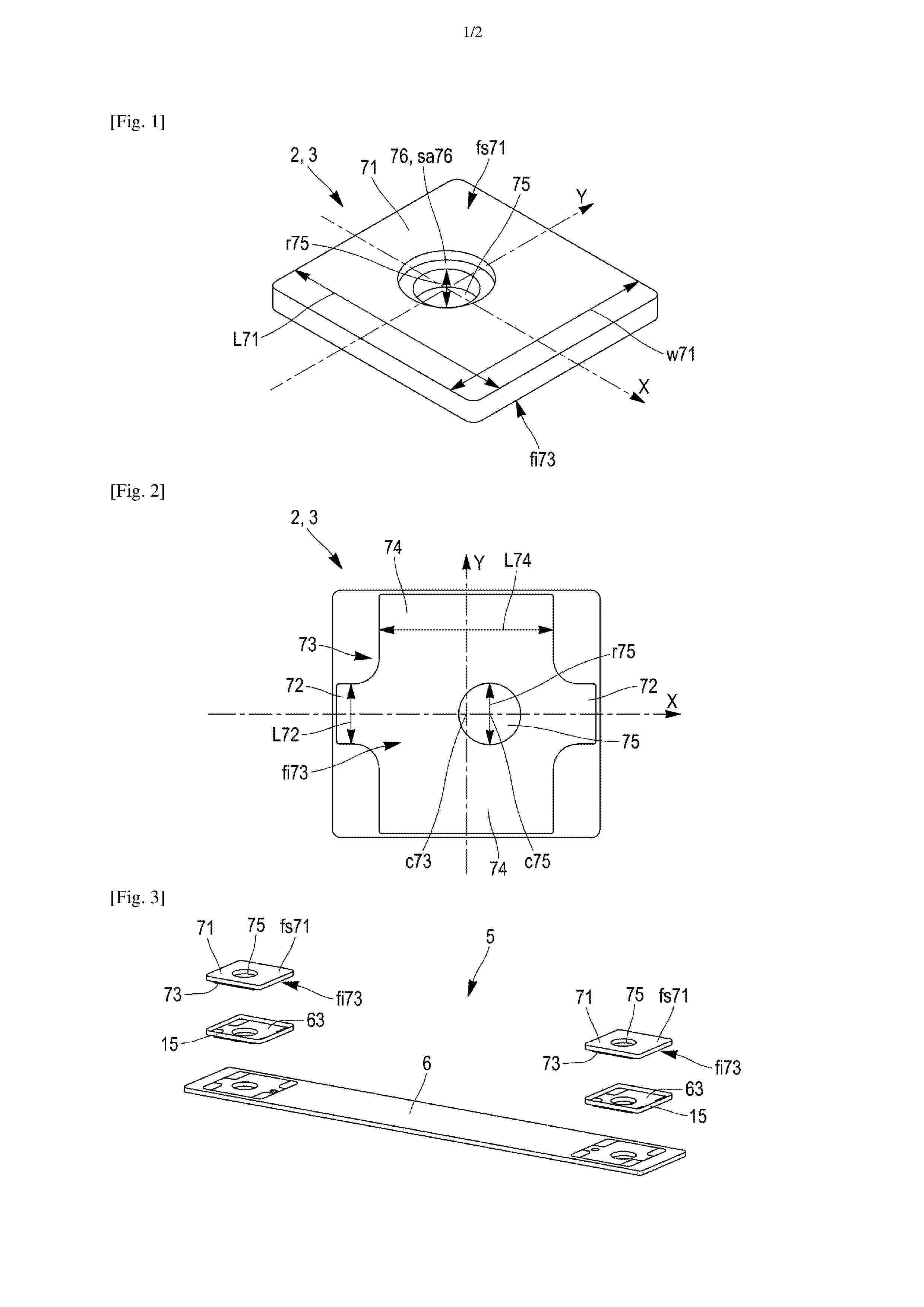
Resumen de: FR3170122A1
L’invention concerne un terminal (2, 3) pour cellule de batterie (1) destiné à être placé en connexion électrique avec un collecteur de courant (10) de la cellule de batterie (1), ledit terminal (2, 3) comprenant une plaque (71) et une empreinte (73) faisant saillie de la plaque (71) et en forme de croix, l’empreinte (73) est destinée à coopérer par complémentarité de forme avec une contre empreinte (63) délimitée par l’organe d’espacement (15), d’une manière bloquant une translation relative et une rotation relative entre le terminal (2, 3) et l’organe d’espacement (15). L’invention concerne également un ensemble (5), et une cellule de batterie (1) comprenant un tel terminal (2, 3). Figure 1
Resumen de: FR3170112A1
La présente invention concerne une composition électrolyte comprenant un sel de lithium, et un complexe à transfert de charge formé à partir d’un précurseur dudit complexe à transfert de charge, accepteur d’électrons, et d’un précurseur dudit complexe à transfert de charge, donneur d’électrons, ledit sel de lithium étant le (fluorosulfonyl)(trifluorométhanesulfonyl) imidure de lithium LiFTFSI, ledit précurseur dudit complexe à transfert de charge, accepteur d’électrons, étant la benzoquinone ou un de ses dérivés, et ledit précurseur dudit complexe à transfert de charge, donneur d’électrons, étant l’hydroquinone ou un de ses dérivés. Elle concerne également un procédé de préparation de ladite composition électrolyte, l’utilisation de ladite composition électrolyte dans une batterie rechargeable au lithium métal ou pour la préparation d’un électrolyte solide d’une batterie rechargeable au lithium métal, un électrolyte solide pour une batterie rechargeable au lithium métal comprenant ladite composition électrolyte, et une batterie rechargeable au lithium métal comprenant ledit électrolyte solide. Figure à publier : figure 1
Resumen de: FR3170117A1
L’invention concerne un élément d’isolation (13) électrique destiné à être interposé entre un collecteur de courant (10) et un couvercle (6) d’une cellule de batterie (1) prismatique, ledit élément d’isolation (13) présentant une face inférieure (fi13) destinée à venir en contact avec le collecteur de courant (10), et comprenant sur sa face inférieure (fi13), des organes de positionnement (47) en relief, destinés à coopérer par complémentarité de forme avec le collecteur de courant (10) d’une manière bloquant une translation relative et une rotation relative entre le collecteur de courant (10) et l’élément d’isolation (13). L’invention concerne également un ensemble (5) et une cellule de batterie (1) comprenant un tel élément d’isolation (13). Figure 2
Resumen de: FR3170125A1
L’invention concerne un organe d’espacement (15) destiné à être interposé entre un couvercle (6) et un terminal (2, 3) d’une cellule de batterie (1) prismatique, ledit organe d’espacement (15) comprenant un corps principal (60) et présentant une face inférieure (fi60) destinée à venir en contact avec le couvercle (6), et une face supérieure (fs60) destinée à venir en contact avec le terminal (2, 3) ; l’organe d’espacement (15) comprenant sur sa face inférieure (fi60), un élément de positionnement (67) en relief en forme de croix, destiné à coopérer par complémentarité de forme avec un organe de positionnement (14) délimité par le couvercle (6), d’une manière bloquant une translation relative et une rotation relative entre le couvercle (6) et l’organe d’espacement (15). L’invention concerne également un ensemble (5), et une cellule de batterie (1) comprenant un tel organe d’espacement (15). Figure 1
Resumen de: FR3170113A1
La présente invention concerne une composition électrolyte comprenant un sel de lithium, un complexe à transfert de charge formé à partir d’un précurseur dudit complexe à transfert de charge, accepteur d’électrons, et d’un précurseur dudit complexe à transfert de charge, donneur d’électrons, un polymère filmogène et un solvant. Elle concerne également un procédé de préparation de cette composition électrolyte, l’utilisation de ladite composition électrolyte pour la préparation d’un électrolyte solide sous la forme d’un film flexible, un procédé de préparation d’un électrolyte solide sous la forme d’un film par enduction de ladite composition électrolyte, l’électrolyte solide sous forme de film flexible susceptible d’être obtenu par la mise en œuvre de ce procédé, un procédé d’élaboration d’une batterie rechargeable au lithium métal comprenant un tel électrolyte solide et une batterie rechargeable au lithium métal, comprenant ledit électrolyte solide. Figure à publier : figure 2
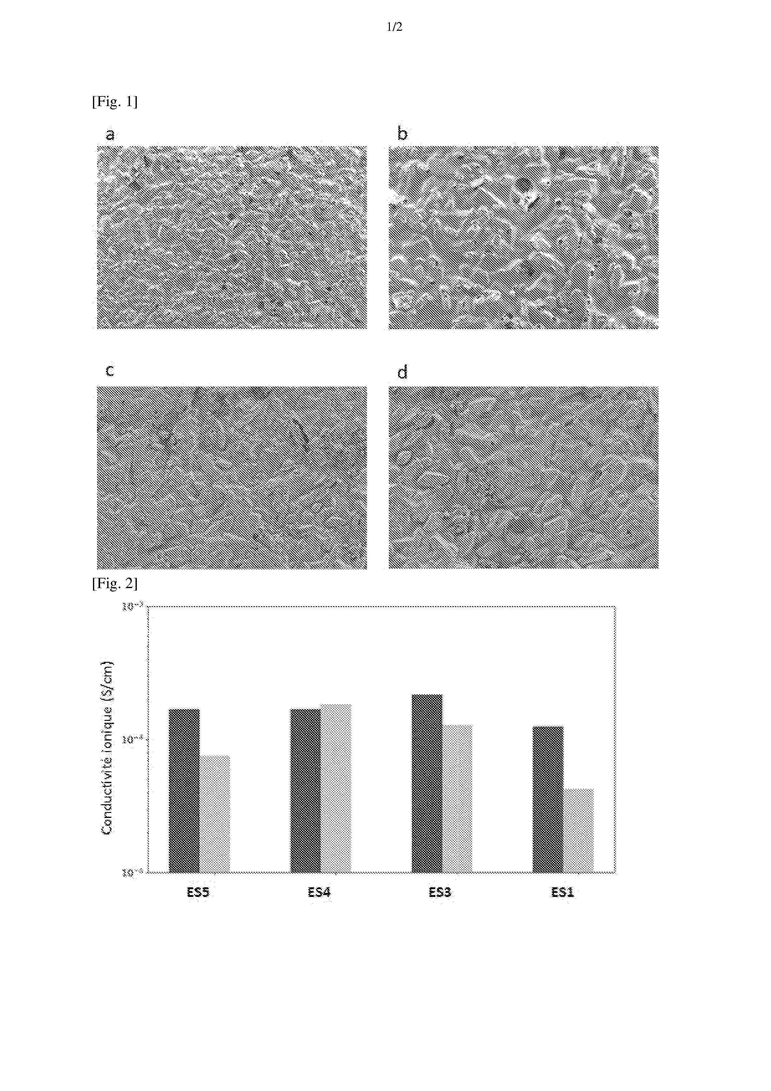
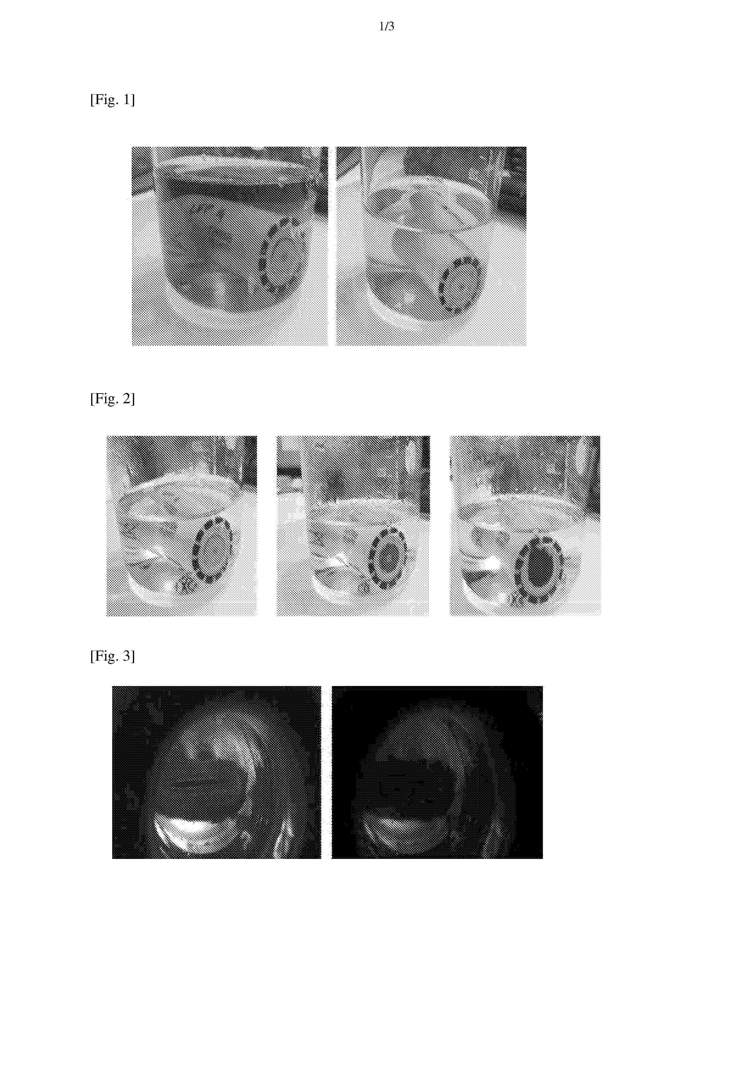
Resumen de: FR3170012A1
La présente invention concerne un procédé pour déterminer la tension entre les bornes d’un objet comprenant les étapes suivantes : (a) mettre en contact, sans connexion électrique, les bornes dudit objet avec une composition comprenant au moins un composé chimique apte à générer un signal optique lorsque soumis à une tension supérieure ou égale à une tension seuil, et (b) détecter un éventuel signal optique émis par le composé chimique moyennant quoi si un signal optique est détecté, la tension entre les bornes dudit objet est supérieure ou égale à la tension seuil. La présente invention concerne également un système électrochimique pour déterminer la tension entre les bornes d’un objet.
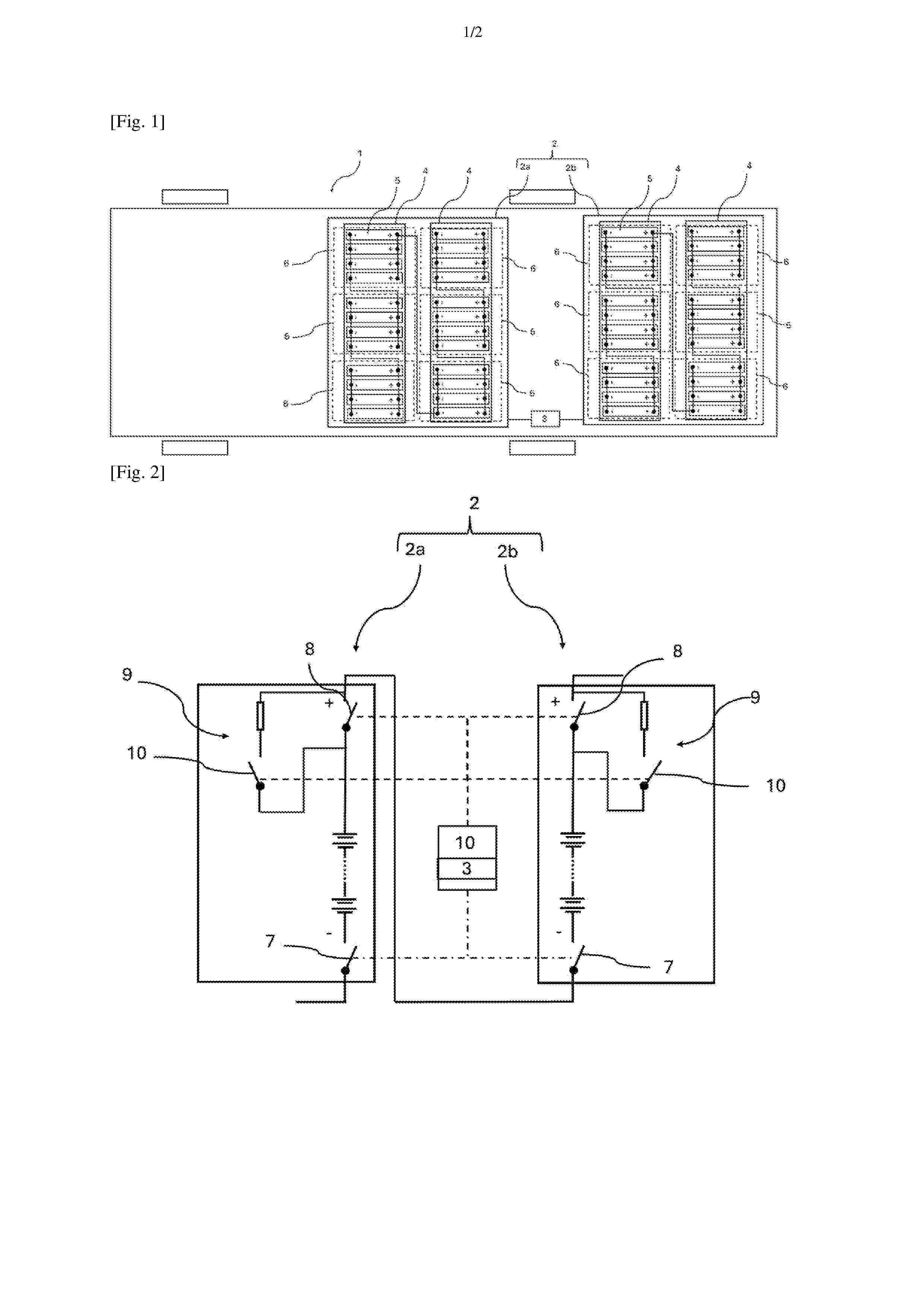
Resumen de: FR3169802A1
Un aspect de l’invention concerne un ensemble 2 de packs batteries 2a, 2b pour véhicule 1 automobile comportant au moins deux packs batteries 2a, 2b agencés pour alimenter un réseau électrique de puissance d’un véhicule 1, chaque pack batterie 2a, 2b comportant des modules 4 ainsi qu’un premier contacteur de puissance 7 et un deuxième contacteur de puissance 8 agencés pour isoler électriquement le pack batterie 2a, 2b, chaque module 4 comportant des cellules 5 électrochimiques, ledit ensemble 1 de packs batteries 2a, 2b étant remarquable en ce que les au moins deux packs batteries 2a, 2b sont électriquement connectés en série. Figure 1
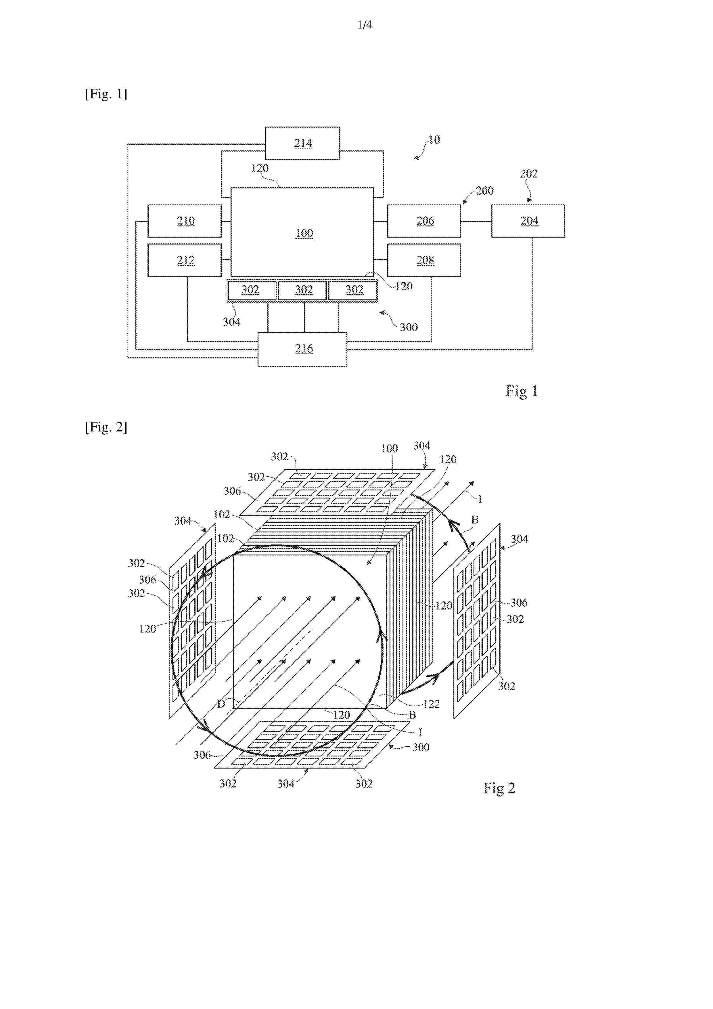
Resumen de: FR3170011A1
Dispositif et procédé de mesure d'un champ magnétique émis par un objet La présente description concerne un dispositif (300) de mesure d'un champ magnétique (B) émis par un objet (100) comprenant un capteur matriciel (304) comprenant une matrice de capteurs magnétiques (302) configurés pour acquérir des mesures successives du champ magnétique, une charge commandable (314) destinée à être connectée électriquement à l'objet (100), et un module (216) configuré pour commander la charge commandable (314) pour faire varier le courant circulant dans l'objet (100) au cours des acquisitions des mesures successives du champ magnétique et pour recevoir les mesures successives du champ magnétique. Figure pour l'abrégé : Fig. 1
Nº publicación: FR3170127A1 19/06/2026
Solicitante:
RENAULT SAS [FR]
RENAULT SAS
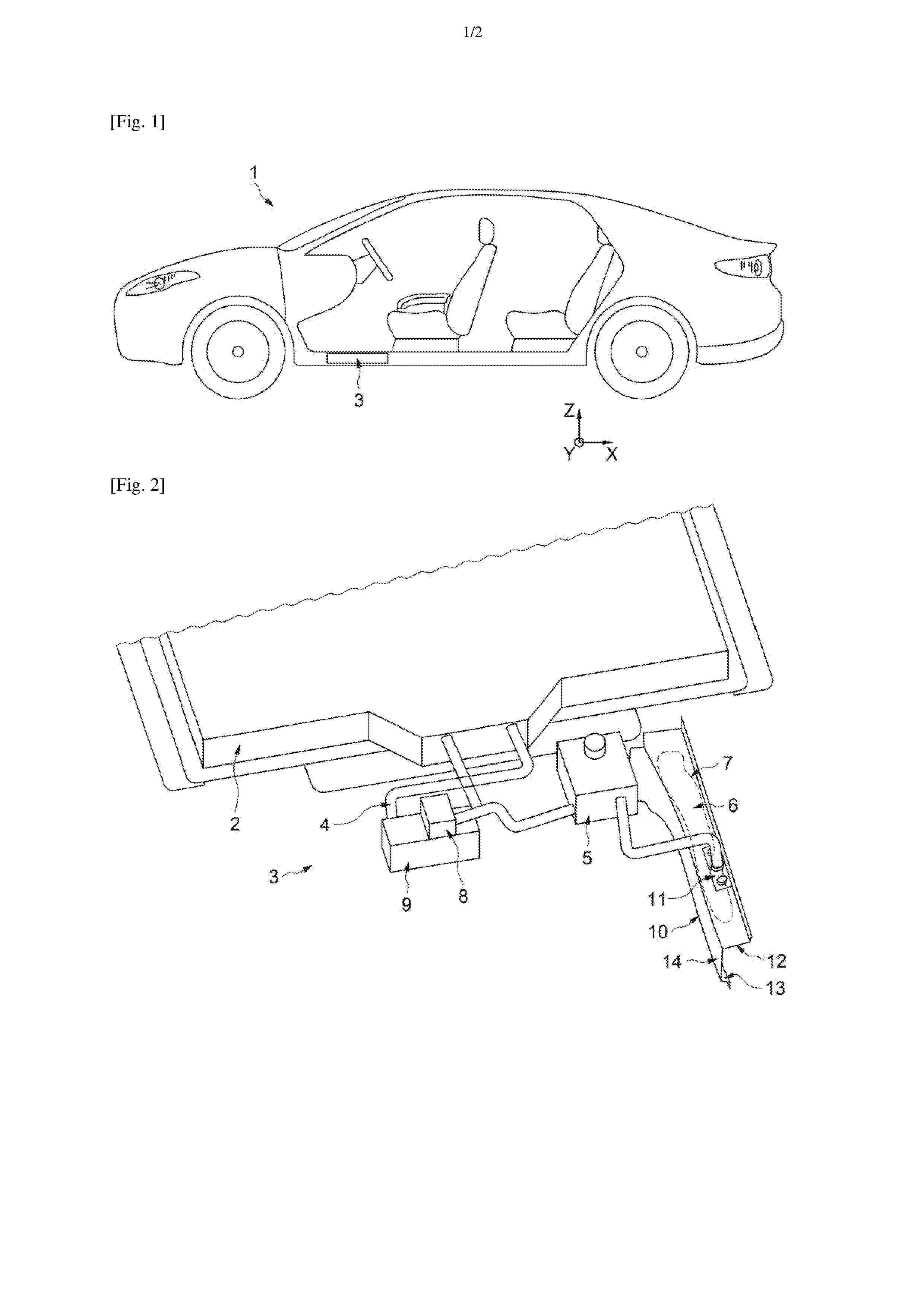
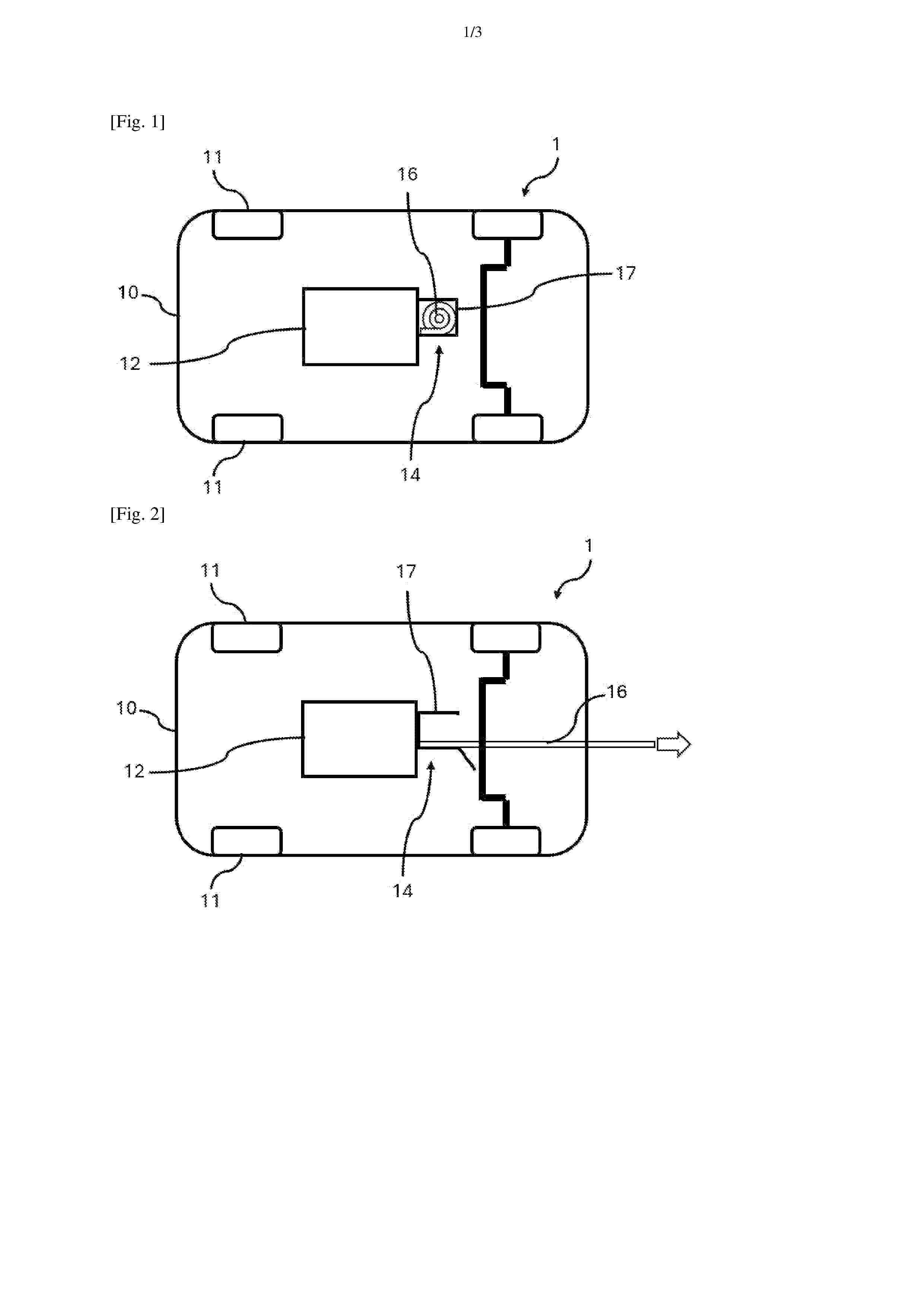
Resumen de: FR3170127A1
Système d’évacuation d’un fluide pour un agencement pour véhicule automobile Agencement (1) pour un véhicule (10) automobile électrique ou hybride, l’agencement (1) comprenant une batterie (12), notamment une batterie (12) au lithium, l’agencement (1) étant caractérisé en ce qu’il comprend un système d’évacuation (14) d’un fluide, notamment d’un gaz, le système d’évacuation (14) étant destiné à être monté sur la batterie (12) de l’agencement (1), le système d’évacuation (14) comprenant une structure tubulaire (16) configurée pour se déployer longitudinalement entre une configuration escamotée et une configuration déployée lorsqu’un seuil de pression prédéterminé est franchi à l’intérieur de la batterie (12) agencée en amont de la structure tubulaire (16) du système d’évacuation (14). Figure pour l’abrégé : Fig.1
 BOPI
BOPI
 Sede Electrónica