Si deseas distinguir tus productos, servicios o ambos de los de otra empresa, es posible que necesites una marca o nombre comercial. Descubre qué son, en qué consiste su procedimiento de registro y qué implica.

Información sobre los plazos de presentación de solicitudes de transformación de marcas de la Unión Europea en marca nacional española. Más información


Si tienes un nuevo dispositivo, producto o procedimiento que resuelva un problema técnico o tenga una ventaja práctica, existen distintas formas de protegerlo en España y en otros países. Descubre cómo hacerlo.

¿Tu innovación reside en la estética, la ornamentación o la apariencia de tu producto? Protégela mediante un diseño industrial. Descubre qué derechos confiere el registro y cómo realizar la tramitación.

Las indicaciones geográficas protegen el nombre de un producto originario de una zona geográfica, a la cual le debe una determinada calidad, reputación u otra característica. Descubre qué son, en qué consiste su procedimiento de registro y qué beneficios conceden.

Las patentes publicadas en todo el mundo son una valiosa fuente de información científica, técnica y comercial.

Si eres emprendedor/a o una empresa y quieres potenciar y mejorar la rentabilidad de tu negocio protegiendo de forma adecuada los activos intangibles de tu organización, en este espacio encontrarás lo necesario.


 496
resultados
496
resultados
 Última actualización
27/06/2026 [06:48:00]
Última actualización
27/06/2026 [06:48:00]


 Resultados 25 a 50 de 496

Resumen de: EP4765260A1
0001 The present disclosure relates to a cartridge type fuel cell membrane humidifier including a housing including an exhaust gas inlet through which exhaust gas discharged from the fuel cell stack is introduced and an exhaust gas outlet configured to discharge the exhaust gas, and a cartridge disposed inside the housing and including a plurality of humidification membranes, the cartridge includes an inner case in which the plurality of humidification membranes are disposed, and a potting unit configured to fix the plurality of humidification membranes, the inner case including a first window portion disposed adjacent to the exhaust gas inlet and including a plurality of windows and a second window portion disposed adjacent to the exhaust gas outlet and including a plurality of windows, and the first window portion including the plurality of windows having different sizes.

Resumen de: EP4765259A1
0001 A humidifier for a fuel cell with a length of a hollow fiber membrane or a gap between hollow fiber membranes, which is adjusted in response to an internal temperature of the humidifier changing with an output condition of the fuel cell, includes a housing, the hollow fiber membrane located inside the housing and inside of which dry air flows and outside of which moist air flows, and a potting material located at opposite ends of the hollow fiber membrane and fixing a terminal end of the hollow fiber membrane, in which a first temperature-sensitive volume-changing member that expands and contracts according to temperature is inserted into the potting material such that, with respect to the first temperature-sensitive volume-changing member, the potting material is divided into an inner potting material located on an inner side of the housing and an outer potting material located on an outer side of the housing and spaced apart from the inner potting material.
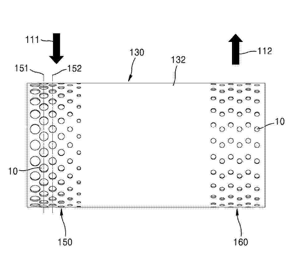
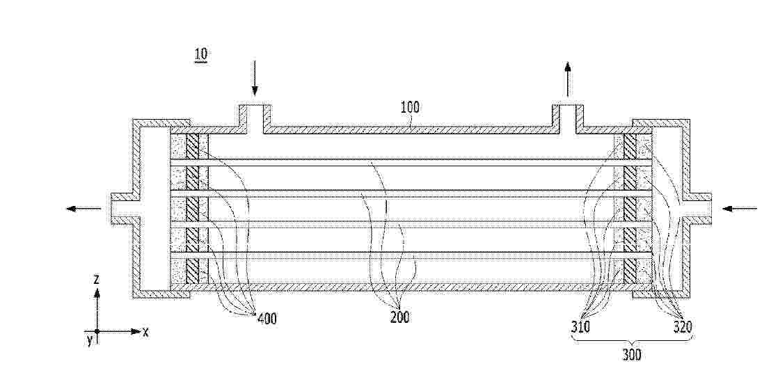
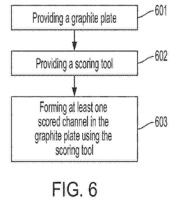
Resumen de: WO2025042767A1
Systems and methods are present for the preconditioning of graphite plates to achieve a graphite bipolar plate with minimal defects. An example of such a system comprises a platform to hold a graphite plate, a scoring tool to score the graphite plate, and a guide system to move the scoring tool along the length of the graphite plate.
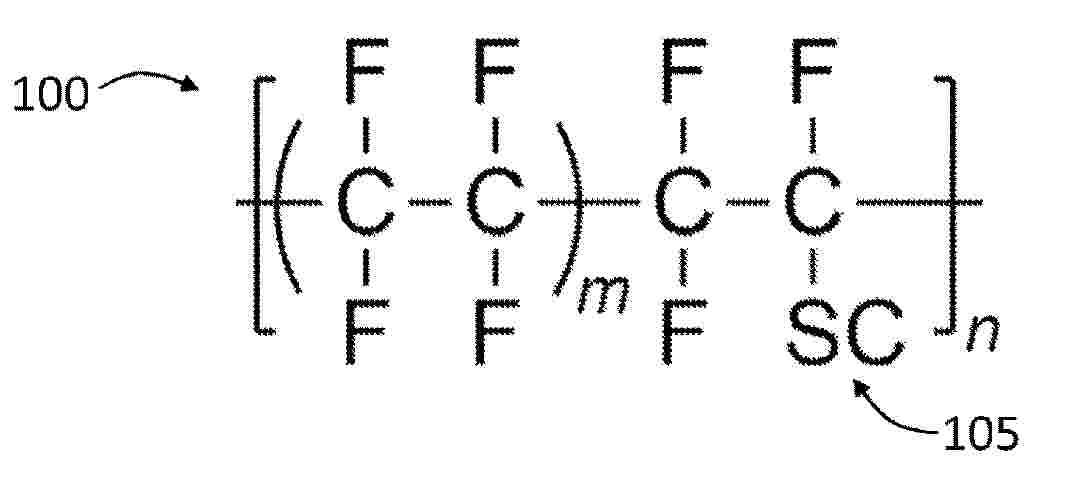
Resumen de: WO2025037119A1
The present invention provides a proton-exchange membrane comprising a blend of first and second ionomers, the first ionomer comprising a first main chain covalently bonded to a first side chain and the second ionomer comprising a second main chain covalently bonded to a second side chain; wherein each of the first and second side chains comprise a sulfonic acid end group; wherein a relaxation modulus of a membrane formed from the first ionomer is at least 10 times less than a relaxation modulus of a membrane formed from the second ionomer, preferably at least 100 times less; and wherein the relaxation modulus of the membrane formed from the second ionomer is greater than 10,000 MPa.
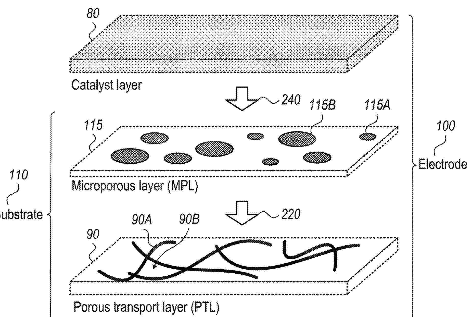
Resumen de: US2025062365A1
Substrates for producing oxygen electrodes, oxygen electrodes, electrochemical devices and productions methods are provided. Substrates include an intermediate microporous layer (MPL) attached to a porous transport layer (PTL) to interface between the PTL and the catalytic layer deposited on the MPL—to provide microstructure compatibility, improved adhesion and better performance of the oxygen electrode produced therefrom. The MPL corresponds to the PTL with respect to the types of metallic material, to provide good electric conductivity, while the metal particle sizes of the MPL are selected to modify the pore sizes of the PTL to reach a predefined pore size distribution of the substrate—which best supports printing, adhesion and performance of the catalyst layer on the substrate. Electrochemical devices such as fuel cells, electrolyzers and reversible devices may include the oxygen electrodes, which may be optimized for the specific application.
Resumen de: WO2025038822A1
The following disclosure relates to electrochemical cell and stacks and components thereof. More specifically, the following disclosure relates to components or systems configured to protect the degradation of an electrochemical cell or stack having a plurality of electrochemical cells. This may be accomplished by operating the cell or stack in a shielding state, instead of completely shutting down operation of the cell or stack. In the shielding state, the at least one electrochemical cell no longer receives enough voltage to generate gas via electrolysis, but still receives enough voltage to maintain a charged capacitance and protect the at least one electrochemical cell from depolarization or discharge.
Resumen de: WO2025037994A1
The subject of this invention is the system for generation and use of hydrogen in which a subsystem for hydrogen generation (U1) contains a reaction chamber (1) with aluminium (2) and sodium hydroxide (3), to which a water nozzle (4) is attached, connected through a duct (5) to a water pump (6). The upper part of the reaction chamber (1) contains an outlet connection (7) connected to a subsystem for hydrogen purification (U2), which is connected to the subsystem for hydrogen oxidation (U3), to which an inlet (27) through oxygen is supplied, is connected. This system is characterised in that the subsystem for hydrogen purification (U2) contains at least one water tank (9) connected to the subsystem for hydrogen oxidation (U3), which outlet (21) is connected through a non-return valve (22) with the condensing tank (23).
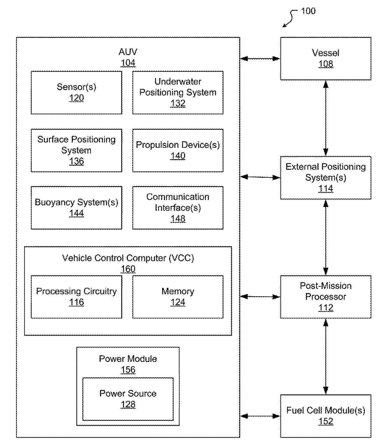
Resumen de: US2025058638A1
0000 An autonomous underwater vehicle (AUV) including a hydrogen fuel cell is provided. The fuel cell control computer is a separate, stand-alone control system that interfaces with a vehicle control computer (VCC) to ensure safe operation of the fuel cell system. Relay logic for disabling the fuel cell enables the VCC to determine if the fuel cell has shut down, ensuring that the AUV system does not send power to the fuel cell system if there are unsafe conditions.
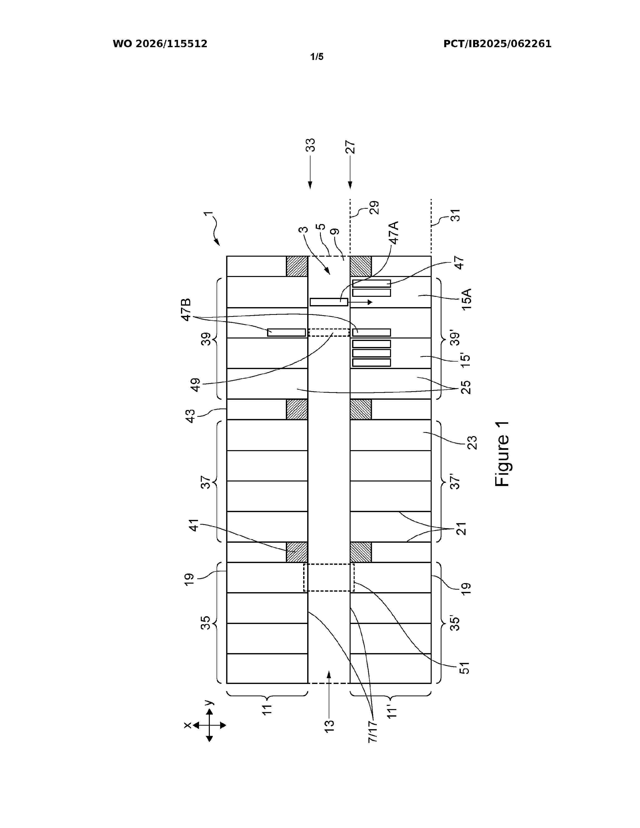
Resumen de: GB2702749A
A redox flow battery system 1 comprises at least one pair of battery modules 35,35'; 37,37'; 39,39 housed in a respective container (15, fig 2) and provided opposite each other with a shared service corridor 3 positioned therebetween, each container including an access portal (57, fig 3) accessible from the shared service corridor. This arrangement provides access to an equipment or power block 47 of each battery module, wherein the equipment block is installable into and removable from (e.g. may slide in and out of) its container by moving the equipment or power block through the container access portal to or from the shared service corridor. The container may be an intermodal (or 'ISO') shipping container. This system reduces the footprint required to deploy a redox flow battery system, facilitating its deployment in constrained spaces, whilst ensuring the system can be serviced and maintained effectively and safely. A method of installing and/or removing an equipment block from a container of the system via the shared corridor is also described. The system is preferably a vanadium redox flow battery system. Use figure 1
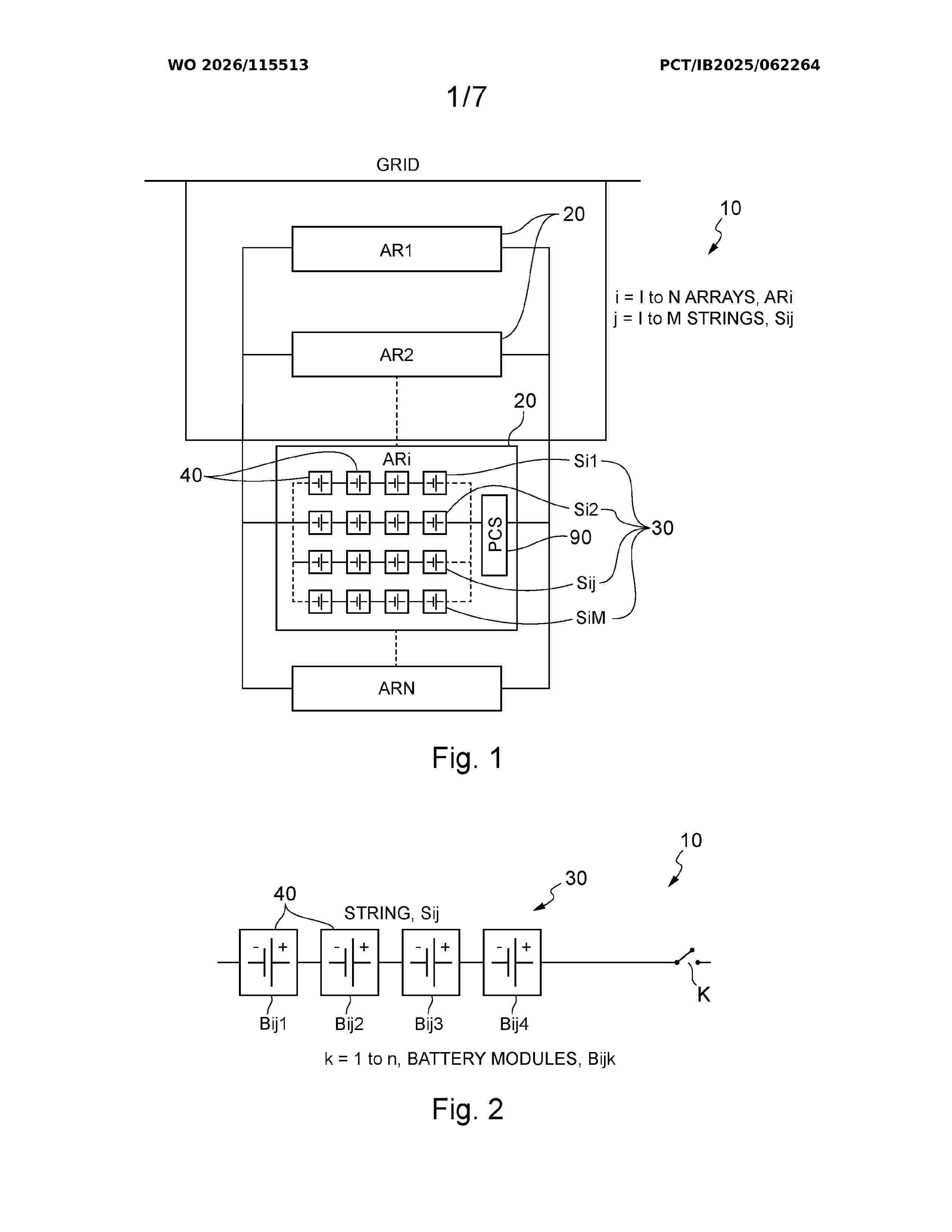
Resumen de: GB2702739A
A redox flow battery system comprises at least one battery module 40 comprising (i) a first cell stack 50 comprising at least one cell sub-stack 60 connected in series, (ii) a second cell stack 50 comprising at least one cell sub-stack 60, the first and second cell stacks being connected in parallel within the battery module, and (iii) an electrolyte tank pair (46, figure 6), wherein the cell sub-stacks of the first and second cell stacks are hydraulically connected in parallel with the tank pair, i.e. the two cell stacks share the same pair of electrolyte tanks. In one aspect, there are at least two of these battery modules connected in series to form a string (30, figures 1 & 2). Alternatively, an array (20, figure 4) comprises at least two strings (30, figure 4) of the battery modules connected in parallel. In a further aspect, the battery module is housed within a standard-sized shipping container. In another aspect, at least one cell stack within at least one of the battery modules is configured to be removable from the battery module. Use figure 3
Resumen de: EP4764377A1
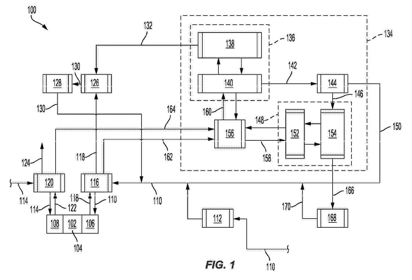
0001 A system and method of generating electrical energy using a fuel cell while decarbonizing an exhaust gas generated by the fuel cell is disclosed. Heat generated by an electrochemical reaction within the fuel cell can be recovered at both an anode side and a cathode side of the fuel cell, and at least some of the recovered heat can be used to preheat each of a fuel feed and an oxidant supplied to the fuel cell. A carbon capture system may be included and used to capture and liquefy carbon dioxide present in an anodic exhaust gas emitted by the fuel cell. At least a liquefaction subsystem of the carbon capture system may receive a cooled refrigerant from a vapor absorption and refrigeration device that cools the refrigerant using heat extracted from heat transfer fluid heated by recovered heat from the anodic exhaust gas and a cathodic exhaust gas.
Resumen de: WO2025099643A1
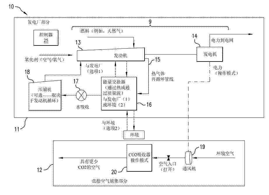
A system for generating electricity with reduced or negative carbon emissions includes a power plant section having an electricity generating unit that includes a solid oxide fuel cell (SOFC) system. The SOFC system includes a SOFC fuel cell reactor and a combustor with an energy exchange path. The combustor is coupled to the fuel cell reactor to combust unutilized fuel. The system also includes a direct air capture (DAC) section having a carbon dioxide (CO2) adsorption device having a CO2 adsorbent material and a ventilator electrically coupled to the electric generator for flowing ambient air through the CO2 adsorption device in a carbon capture mode. The CO2 adsorption device is coupled to and in energy communication with the energy exchange path for releasing adsorbed CO2 in a carbon release mode.
Resumen de: WO2025093374A1
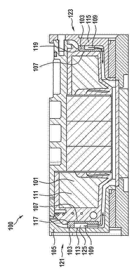
The invention relates to an air compressor (100) for conveying air, said air compressor (100) comprising: - a stator (101), - a cooling device (103), and - a cladding (105) which surrounds the stator (101), said cooling device (103) comprising: - a main part (107) and - a number of air-guiding elements (109) formed on the surface of the main part (107), wherein the cooling device (103) overlaps with a winding head (111) of the stator at least at the end face in a region between the winding head (111) and the cladding (105), and the cladding (105) has a number of cladding receiving areas (113, 115), by means of which the cooling device is mechanically coupled to the cladding. The stator has a number of stator receiving areas (117, 119), by means of which the cooling device is mechanically coupled to the stator (101), and the cladding (105), together with the air guiding elements (109) and the main part (107), forms an air guiding path which is configured so as to guide an air mass flow along the stator (101).
Resumen de: US12617537B1
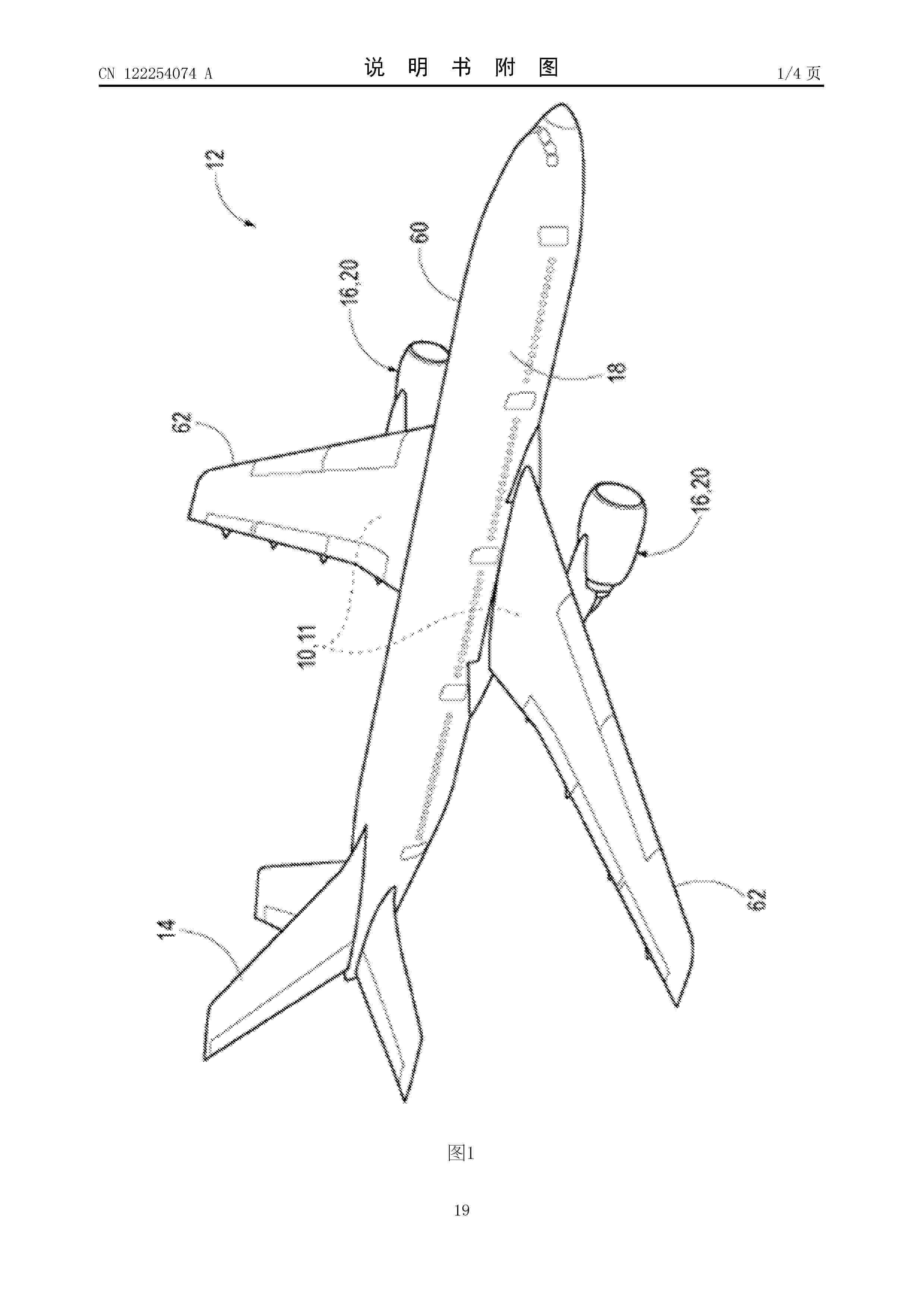
Hybrid propulsion systems that utilize liquid natural gas solid oxide fuel cells in a manner practical for use in aircraft that avoid the use of heavy batteries, provide transient response times suitable for use in aircraft, and/or simplify reactant pre-conditioning systems using a compressor and turbine pair operatively coupled to the solid oxide fuel cell. Such hybrid propulsion systems for an aircraft may include a liquid natural gas solid oxide fuel cell, a motor driven by electric power from the solid oxide fuel cell, a gearbox operatively coupled to the motor, and a turbofan engine configured to generate thrust for the aircraft. The turbofan engine may be configured to provide electric power and shaft power and may include a duct fan that is operatively coupled to the motor via the gearbox, with the duct fan being driven by mechanical power from the gearbox and by the motor.
Resumen de: JP2025174444A
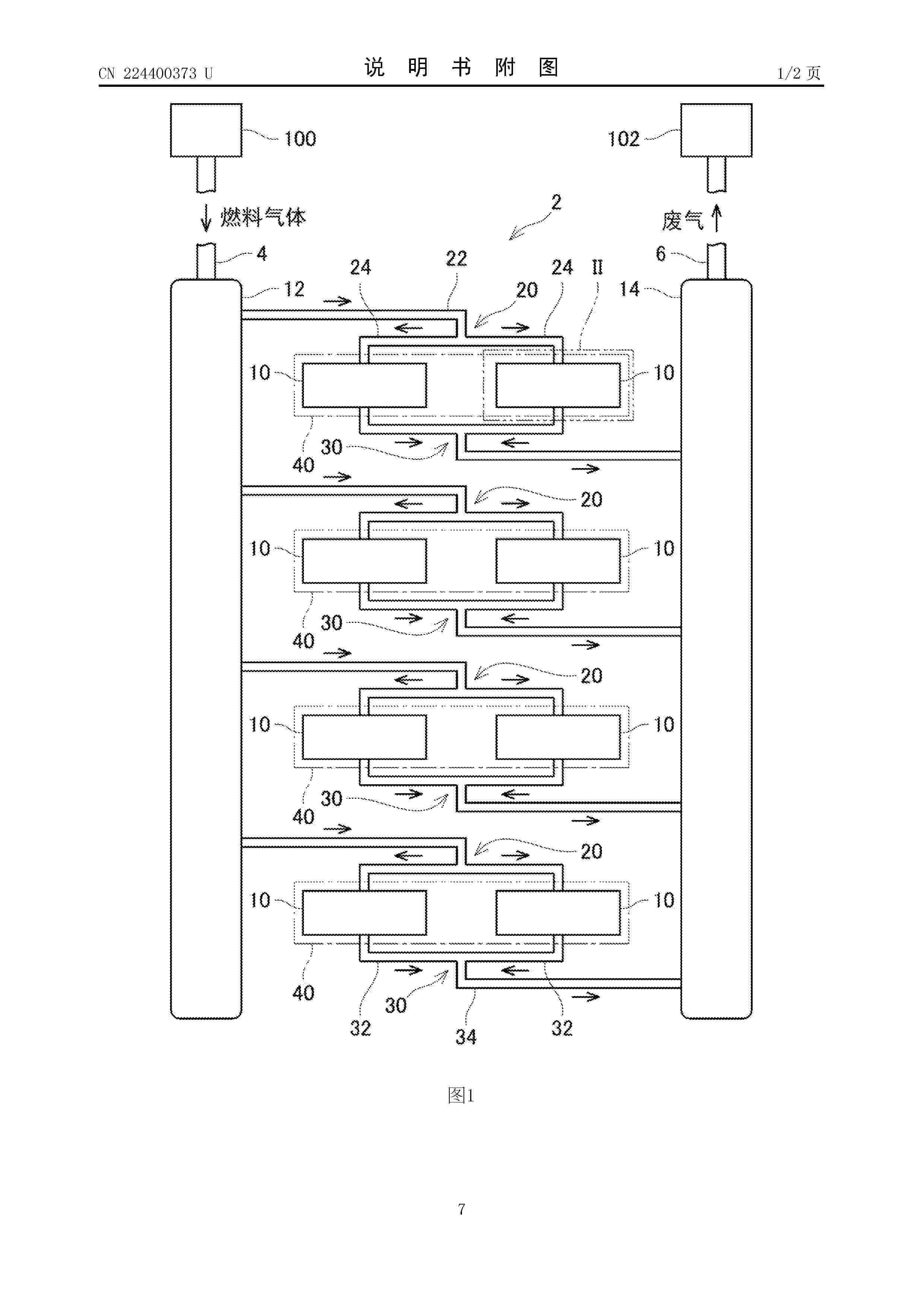
To provide a technique capable of stably generating large electric power.SOLUTION: A fuel cell system comprises a plurality of fuel cells, and a plurality of gas supply pipes connected to the plurality of fuel cells and supplying fuel gases to the plurality of fuel cells. The plurality of gas supply pipes supply the fuel gases to the plurality of fuel cells in parallel. The plurality of fuel cells are electrically connected in parallel.SELECTED DRAWING: Figure 1
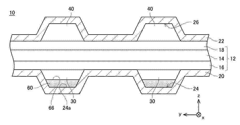
Resumen de: WO2025131321A1
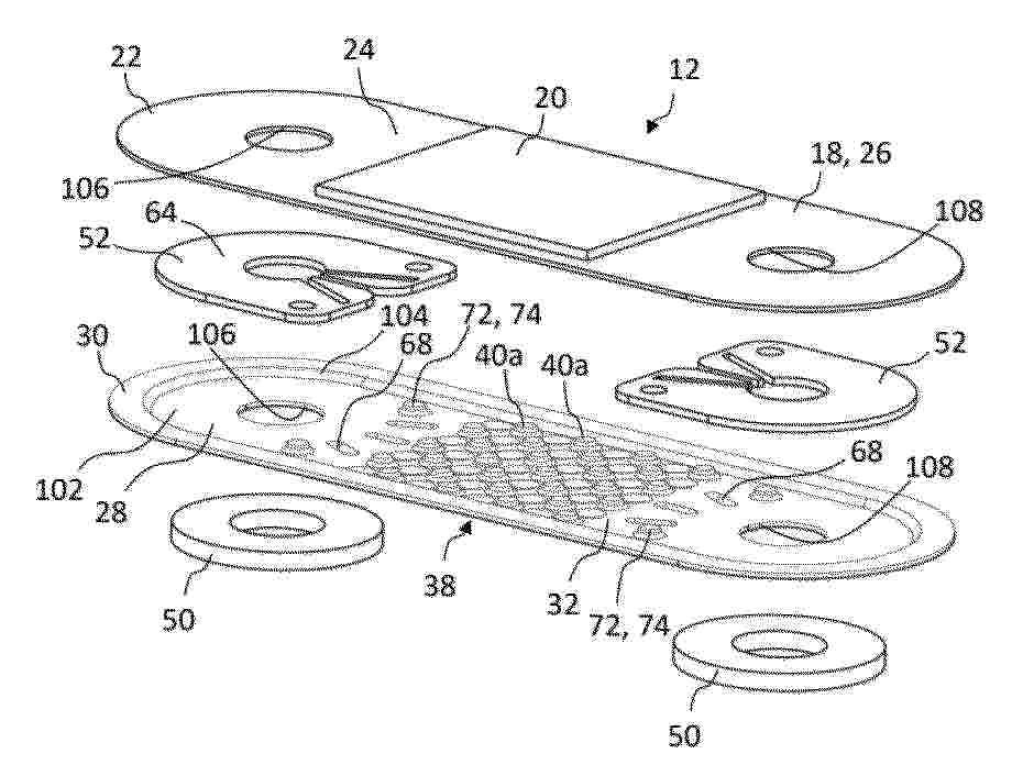
The invention relates to a cell unit (12) comprising a cell layer (18) and an interconnector plate (28), wherein a periphery (22) of the cell layer (18) is attached to a periphery (30) of the interconnector plate, wherein a central portion (24) of the cell layer and a central portion (32) of the interconnector plate define a fluid volume (34) therebetween, and wherein a fluid guidance insert (52) is disposed in the fluid volumes, said fluid guidance insert defining a fluid channel system for conveying fluid between at least one fluid port of the cell unit and the fluid volume.
Resumen de: WO2025131203A1
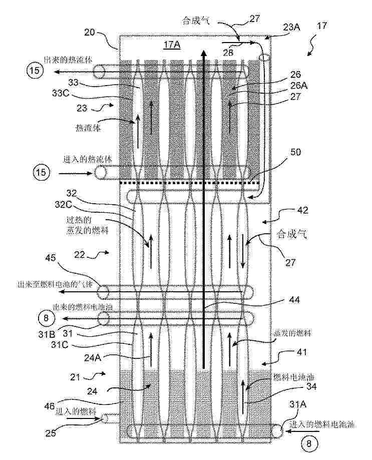
A fuel cell system and a method of its operation, a vehicle and a method for propelling the vehicle with the fuel cell system. In a fuel cell system (1), an evaporator (41), a superheater (42) and a reformer (26) are provided inside a pressurised container (20) to provide a compact fuel processing unit 5 (17).
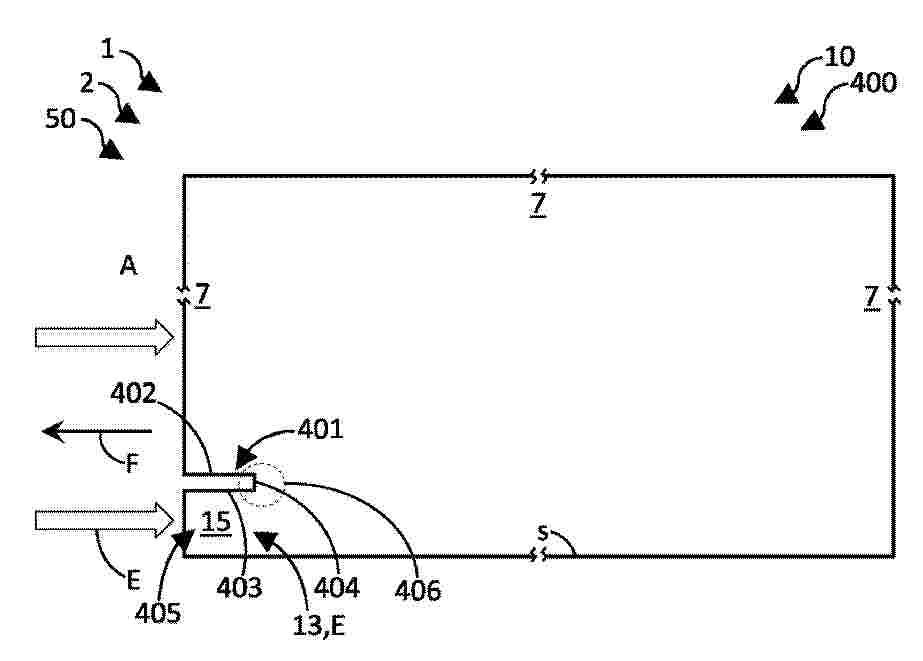
Resumen de: EP4574665A1
0001 An energy conversion arrangement (10) for an aircraft (1), an energy system (2), a propulsion unit (5), and an aircraft (1) comprising an energy conversion arrangement (10) and/or an energy system (2) are provided, wherein the energy conversion arrangement (10) comprises at least one exhaust outlet (13) for letting out exhausts (E) produced by a fuel conversion device (11), in particular a fuel cell system (70), for converting at least one fuel to electrical and/or mechanical energy in the fuel conversion device (11); and at least one exhaust assembly (400) configured to admix a stream of the exhausts (E) from the at least one exhaust outlet (13) with ambient air (A) from the ambient surroundings (7) in at least one mixing zone (406) to promote a growth of water droplets through at least partly condensing water vapor contained in the exhausts (E) in the mixing zone (406).
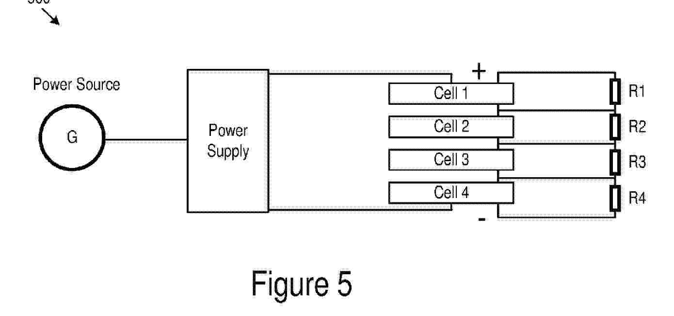
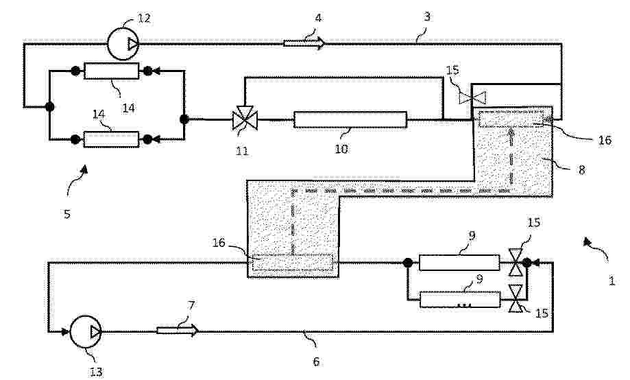
Resumen de: WO2025113862A1
Pre-heating system (1) for a vehicle (2) comprising a first cooling circuit (3) comprising a first coolant (4) circulating therein and connected to a fuel cell system (5) of the vehicle (2) for regulating the operating temperature of said fuel cell system (5), a second cooling circuit (6) comprising a second coolant (7) circulating therein, the second cooling circuit (6) being separated from the first cooling circuit (3), and a heat exchanger (8) for thermally coupling the first cooling circuit (3) to the second cooling circuit (6) and for determining a heat exchange between the first coolant (4) and the second coolant (7), wherein the second cooling circuit (6) comprises at least a high power resistor (9).
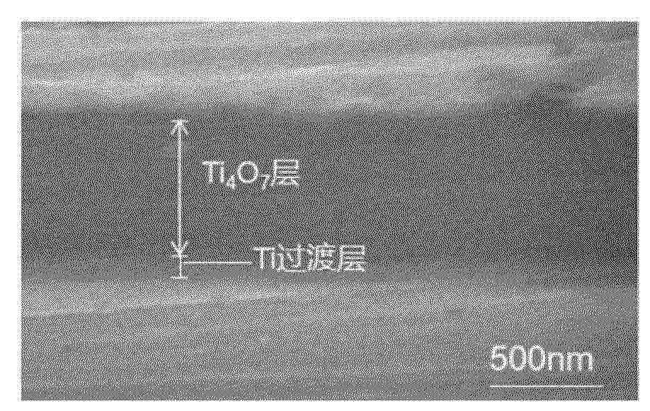
Resumen de: CN122267225A
本发明公开了一种不锈钢双极板表面耐腐蚀导电薄膜及其制备方法;所述方法采用高功率脉冲磁控溅射技术,包括基体预处理、氩离子清洗、Ti过渡层溅射、以及Ti4O7层的反应溅射等步骤。本发明工艺窗口宽,通过调控工艺参数,可在室温下制备出致密、附着力强、兼具高耐腐蚀性和导电性的Ti4O7薄膜,该薄膜适用于高性能质子交换膜燃料电池双极板的表面改性。
Resumen de: CN122267228A
本发明提出一种促进燃料电池的气体流路内的生成水的排水,并且减少气体流路内的压力损失的技术。燃料电池具有:膜电极复合体;及隔板,其与膜电极复合体接触,并在与膜电极复合体接触的表面上设置有第1凹部。并且,燃料电池具有第1气体流路,其由第1凹部和膜电极复合体包围。第1气体流路具有第1部分和配置于比第1部分更靠下游侧的第2部分。燃料电池具有变更第1部分的流路的截面积和第2部分的流路的截面积的截面积变更装置。截面积变更装置能够将第1部分的流路的截面积和第2部分的流路的截面积分别独立地进行变更。
Resumen de: CN122267227A
本发明公开了一种气液双通道微孔层、其制备方法及应用,包含以下步骤:步骤S1,将醋酸锌溶解于甲醇溶液中,分散得到溶液A,将2‑甲基咪唑、十六烷基三甲基溴化铵、月桂酸钠依次溶解于甲醇溶液中,分散得到溶液B;步骤S2,将所述溶液A加入所述溶液B中,搅拌后,去除溶剂得到沉淀,将沉淀真空干燥后得到前驱体p‑ZIF‑8,将所述前驱体p‑ZIF‑8进行高温热处理,得到多孔碳材料p‑ZIF‑8‑C;步骤S3,将所述多孔碳材料p‑ZIF‑8‑C、疏水剂与溶剂混合,经分散后配制成浆料,将所述浆料分多次涂布于碳纤维基底上,涂布后采用干燥方式去除溶剂,焙烧后得到表面具有裂纹结构的气液双通道微孔层。本发明通过精准调控碳材料孔径和实现微孔层裂纹可调,提高了膜电极内部水管理和气体传输能力,进而提高了燃料电池的性能。
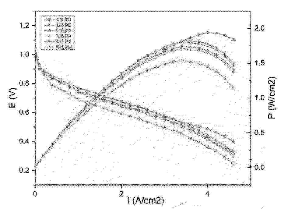
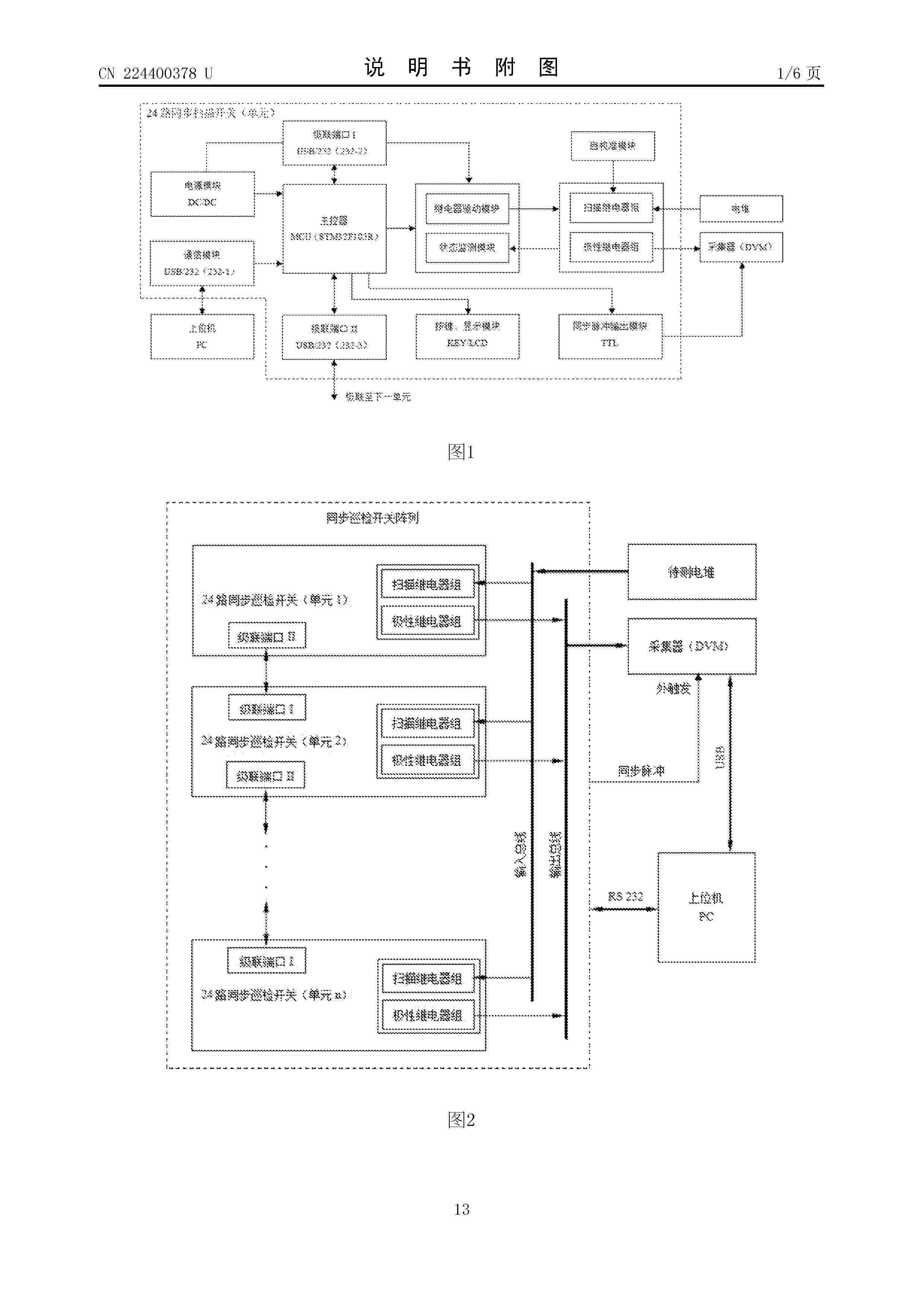
Resumen de: CN224400378U
本实用新型提供一种融合电解制氢及氢燃料电池电堆的电压巡检开关,包括:电堆、扫描继电器组、极性继电器组、数据采集器、主控器、第一输出总线、第二输出总线;所述电堆包括N个串联的电池,第N个电池的负极与第N个引线的左端连接,第N个电池的正极与第N+1个引线的左端连接;所述扫描继电器组包括N+1个通道切换继电器;所述极性继电器组包括第一极性切换继电器和第二极性切换继电器;所述主控器具有N+1个选通道信号引脚、第一选极性信号引脚和第二选极性信号引脚,还具有同步采集信号引脚。本实用新型开关扫描模块可实现单节电池两端的正负极性的自动调整,提供开关动作与数据采集之间的操作时序协同功能。
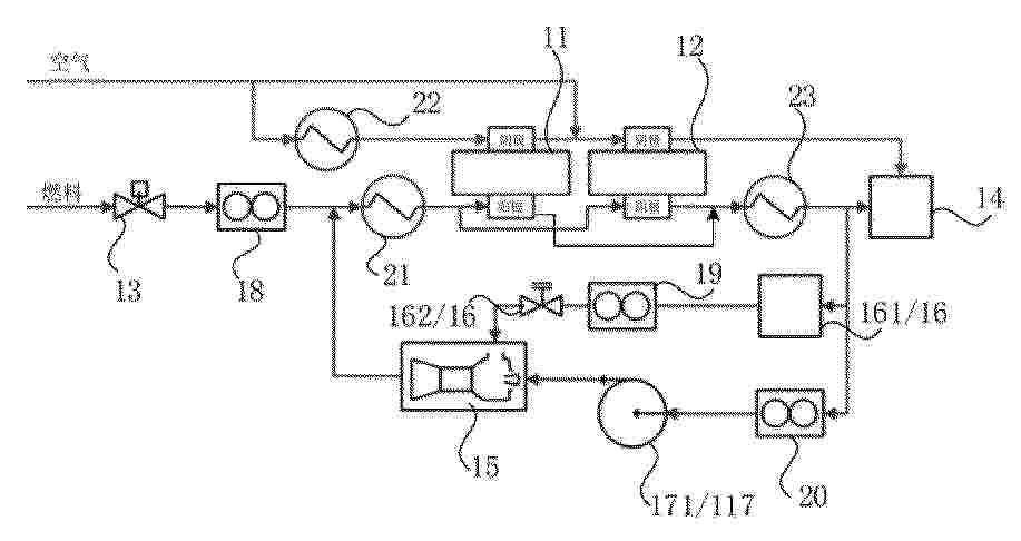
Resumen de: CN122267235A
本发明公开了一种SOFC发电系统及其控制方法。包括第一级电堆、第二级电堆、供气电磁阀、尾气燃烧器、引射器、第一支路和第二支路,第一支路包括冷凝器和压力调节阀,第二支路包括中温循环泵;第一级电堆与第二级电堆的阴极串联连接,第一级电堆与第二级电堆的阳极入口均与供气电磁阀连接;在第一支路开启时,冷凝器、压力调节阀和引射器启动,第二级电堆的阳极出口、冷凝器、压力调节阀、引射器和第一级电堆的阳极入口依次连接,以形成第一循环流路;在第二支路开启时,中温循环泵和引射器启动,第二级电堆的阳极出口、中温循环泵、引射器和第一级电堆的阳极入口依次连接,以形成第二循环流路。以实现系统发电功率、燃料利用率的自由调节。
Nº publicación: CN224400445U 23/06/2026
Solicitante:
三峡电能有限公司
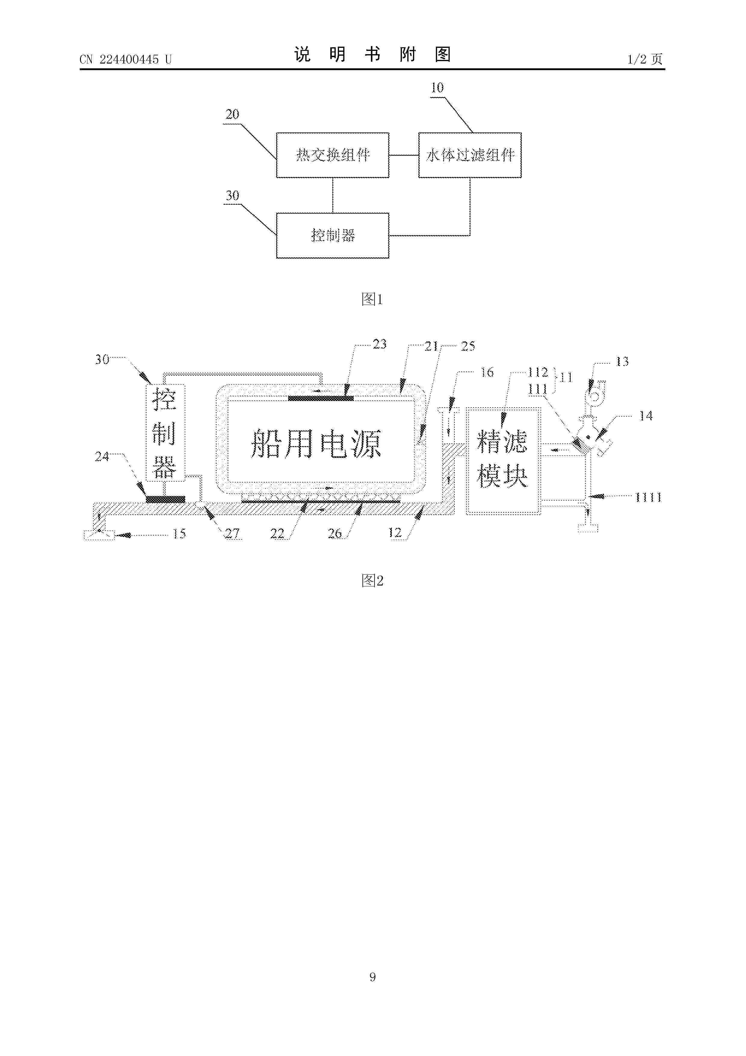
Resumen de: CN224400445U
本申请提供一种船用电源的集成式循环冷却系统,包括:水体过滤组件、热交换组件和控制器;水体过滤组件中的多个过滤单元沿水体输送管道分段设置;水体输送管道的进水端安装有流量调节阀,出水端安装有止逆阀;输水泵与流量调节阀相连;热交换组件中的循环回路紧贴于船用电源的外围;板式换热器的一侧与循环回路的底部通道接触连接,另一侧与水体输送管道的外管壁接触连接;两个温度传感器分别设置于电池舱环境和水体输送管道的外管壁;控制器的传感信号采集端分别与两个温度传感器电连接,控制信号输出端分别与输水泵和流量调节阀电连接。本申请所述的系统采用高效散热、防腐蚀及轻量化设计,能够满足船舶领域对电源系统冷却的高要求。
 BOPI
BOPI
 Sede Electrónica