Si deseas distinguir tus productos, servicios o ambos de los de otra empresa, es posible que necesites una marca o nombre comercial. Descubre qué son, en qué consiste su procedimiento de registro y qué implica.

Información sobre los plazos de presentación de solicitudes de transformación de marcas de la Unión Europea en marca nacional española. Más información


Si tienes un nuevo dispositivo, producto o procedimiento que resuelva un problema técnico o tenga una ventaja práctica, existen distintas formas de protegerlo en España y en otros países. Descubre cómo hacerlo.

¿Tu innovación reside en la estética, la ornamentación o la apariencia de tu producto? Protégela mediante un diseño industrial. Descubre qué derechos confiere el registro y cómo realizar la tramitación.

Las indicaciones geográficas protegen el nombre de un producto originario de una zona geográfica, a la cual le debe una determinada calidad, reputación u otra característica. Descubre qué son, en qué consiste su procedimiento de registro y qué beneficios conceden.

Las patentes publicadas en todo el mundo son una valiosa fuente de información científica, técnica y comercial.

Si eres emprendedor/a o una empresa y quieres potenciar y mejorar la rentabilidad de tu negocio protegiendo de forma adecuada los activos intangibles de tu organización, en este espacio encontrarás lo necesario.


 544
resultados
544
resultados
 Última actualización
01/10/2026 [07:28:00]
Última actualización
01/10/2026 [07:28:00]


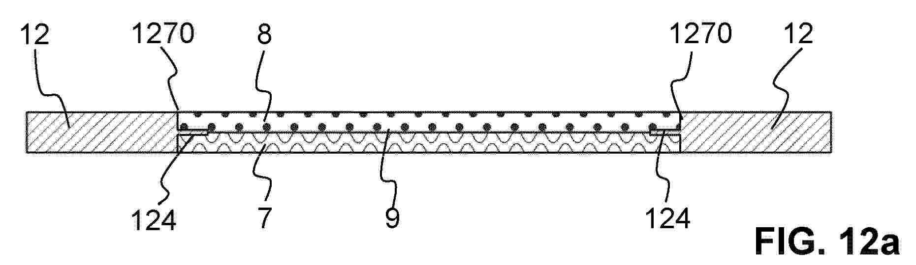
Resumen de: EP4815075A1
A reaction chamber of a membrane-less redox flow battery comprises a bottom phase (7) of a first electrolyte having a first density and a top phase (8) of a second electrolyte having a second density, the first and second electrolytes being immiscible with each other. The bottom phase (7) and the top phase (8) have a main flow direction (F) in horizontal direction of the reaction chamber. The top phase (8) lies on top of the bottom phase (7), wherein the bottom phase (7) and the top phase (8) together form a liquid interface (9) between them. The reaction chamber comprises an interface window (127) defined by a wall (1270) surrounding the liquid interface (9). It also comprises a pinning structure (124) protruding the wall (1270) and extending between the bottom phase (7) and the top phase (8) into the interface window (127). The reaction chamber can be scaled-up and it is stackable.

Resumen de: EP4815076A2
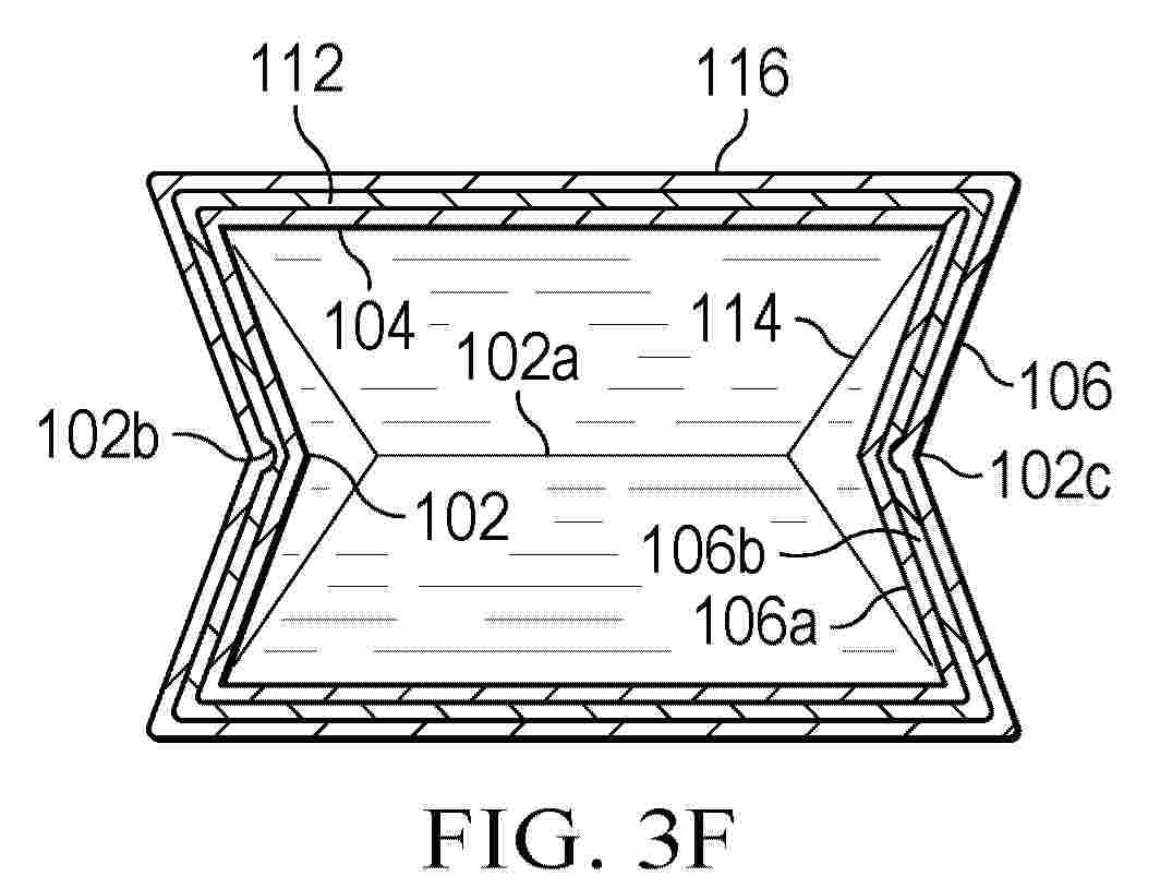
0001 A collapsible fuel cell (100) for an aircraft (10). The fuel cell (100) comprising: an inner textile support substrate (112) having an outer surface including one or more textile crease lines (102b) forming a fold pattern; and a spray coated outer shell layer (116) conforming to the outer surface of the inner textile support substrate (112) to form the fuel cell (100), the fuel cell collapsible along the fold pattern formed by the one or more textile crease lines (102b).
Resumen de: EP4813500A1
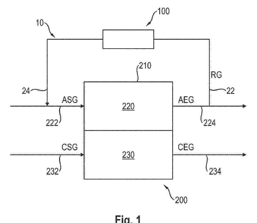
The invention is related to a hydrogen concentrator (100) of a fuel cell system (200) for concentrating hydrogen of a recirculation gas (RG) being recirculated of an anode exhaust gas (AEG) from an anode section (220) of a fuel cell stack (210) of the fuel cell system (200) by nitrogen sorption. The hydrogen concentrator (100) comprises a recirculation path (10) for conducting the recirculation gas (RG), wherein the recirculation path (10) comprises a recirculation path inlet (22) which is connectable to an anode discharge section (224) of the anode section (220) and a recirculation path outlet (24) which is connectable to an anode supply section (222) of the anode section (220), and at least one sorption device (12) arranged in the recirculation path (10) for sorption of nitrogen in the recirculation gas (RG).
Resumen de: EP4815072A1
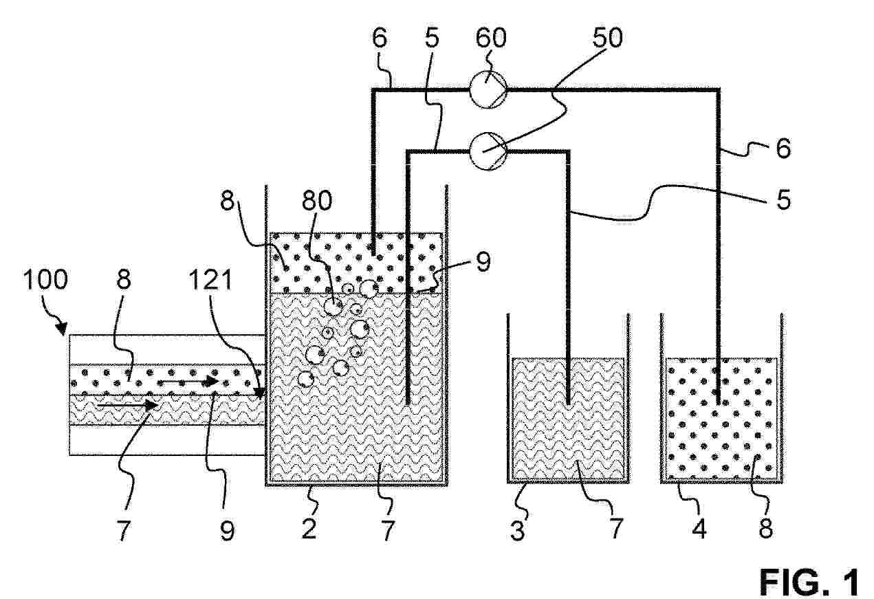
A membrane-less redox flow battery comprises a reaction chamber (100), a first electrolyte and a second electrolyte, and at least one tank. The first electrolyte and the second electrolyte are immiscible with each other. The first electrolyte has a first density, and the second electrolyte has a second density, wherein the first density is higher than the second density. The first electrolyte forms a bottom phase (7) within the reaction chamber (100) and the second electrolyte forms a top phase (8) within the reaction chamber (100). The top phase (8) lies on top of the bottom phase (7), the top phase (8) and the bottom phase (7) forming a liquid interface (9) between them and the top phase (8) and the bottom phase (7) flow in horizontal direction through the reaction chamber (100). The reaction chamber (100) comprises at least one outlet (120, 121) through which the bottom phase (7) and the top phase (7) can exit the reaction chamber (100) and enter the tank. The tank is a separation tank (2) for separating the bottom phase (7) from the top phase (8) by gravity.
Resumen de: EP4815077A1
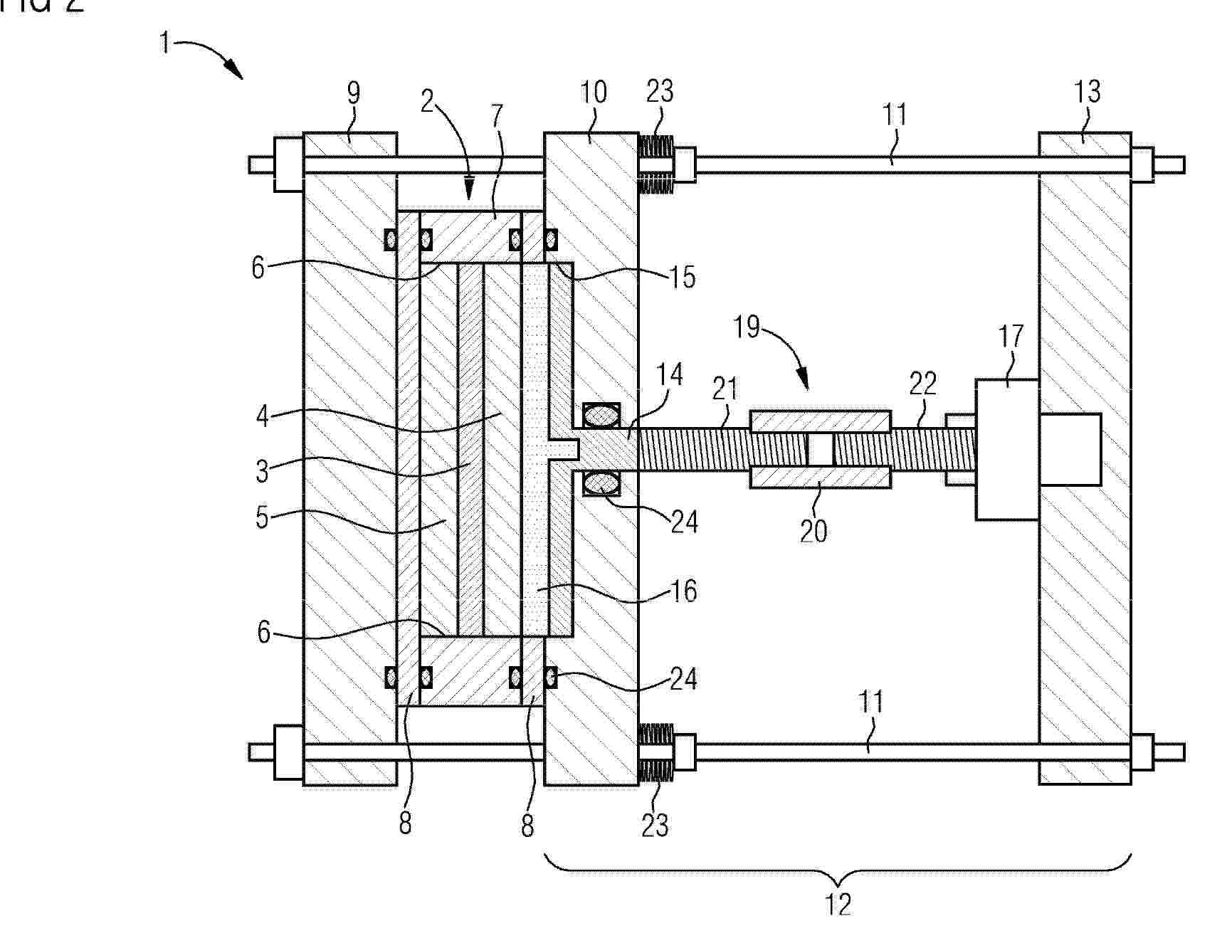
0001 The invention is about an electrochemical energy conversion system (1), with electrochemical cells (2), each electrochemical cell (2) comprising a membrane electrode assembly (3) arranged between a cathodic gas diffusion layer (4) and an anodic gas diffusion layer (5) and on front sides (6) surrounded by a frame (7) and enclosed between bipolar plates (8), the electrochemical cells (2) being compressed between first and second end plates (9, 10) by means of tie rods (11), wherein a pressure unit (12) is arranged between the second end plate (10) and a third end plate (13) opposite the first end plate (9) in relation to the second end plate (10), the pressure unit (12) comprising a piston (14) that acts on the electrochemical cells (2) through an opening (15) in the second end plate (10) and the directly neighbouring bipolar plate (8), the piston (14) having an attachment (16) for different pressure profiles.
Resumen de: EP4814276A1
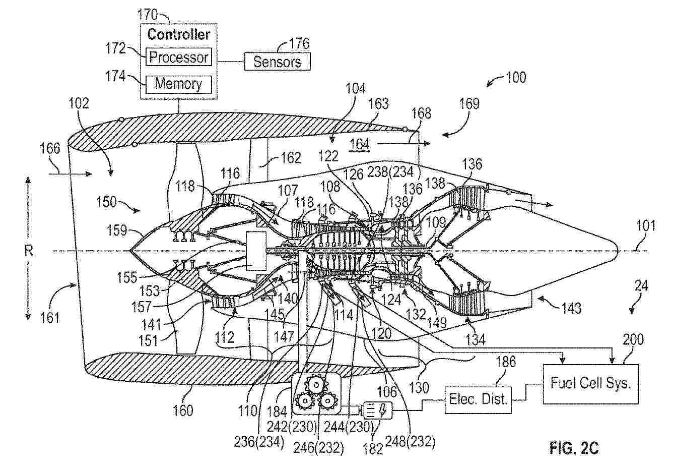
0001 A propulsion and electrical system (20, 22, 24, 26) for an aircraft (10) comprises a turbine engine (100) including a compressor (110) configured to generate compressed air (147) containing oxygen. A portion of the compressed air is provided as bleed air (230) to a bleed air valve assembly (300, 302, 304, 306). The bleed air valve assembly is configured to regulate the bleed air (230) to generate pressurised air (260) containing oxygen. A fuel cell (210) is fluidly connected to a hydrogen source (250) and to the bleed air valve assembly (300, 302, 304, 306), and is configured to receive the pressurised air (260) and the hydrogen (252) to generate electrical power (218). The bleed air (230) may include high-pressure bleed air (244) and low-pressure bleed air (242) extracted from different stages of the compressor (110). The bleed air valve assembly may also be connected to an ambient air source (226) and include an ejector (350, 360) or bypass flow paths (346, 348).
Resumen de: EP4815071A1
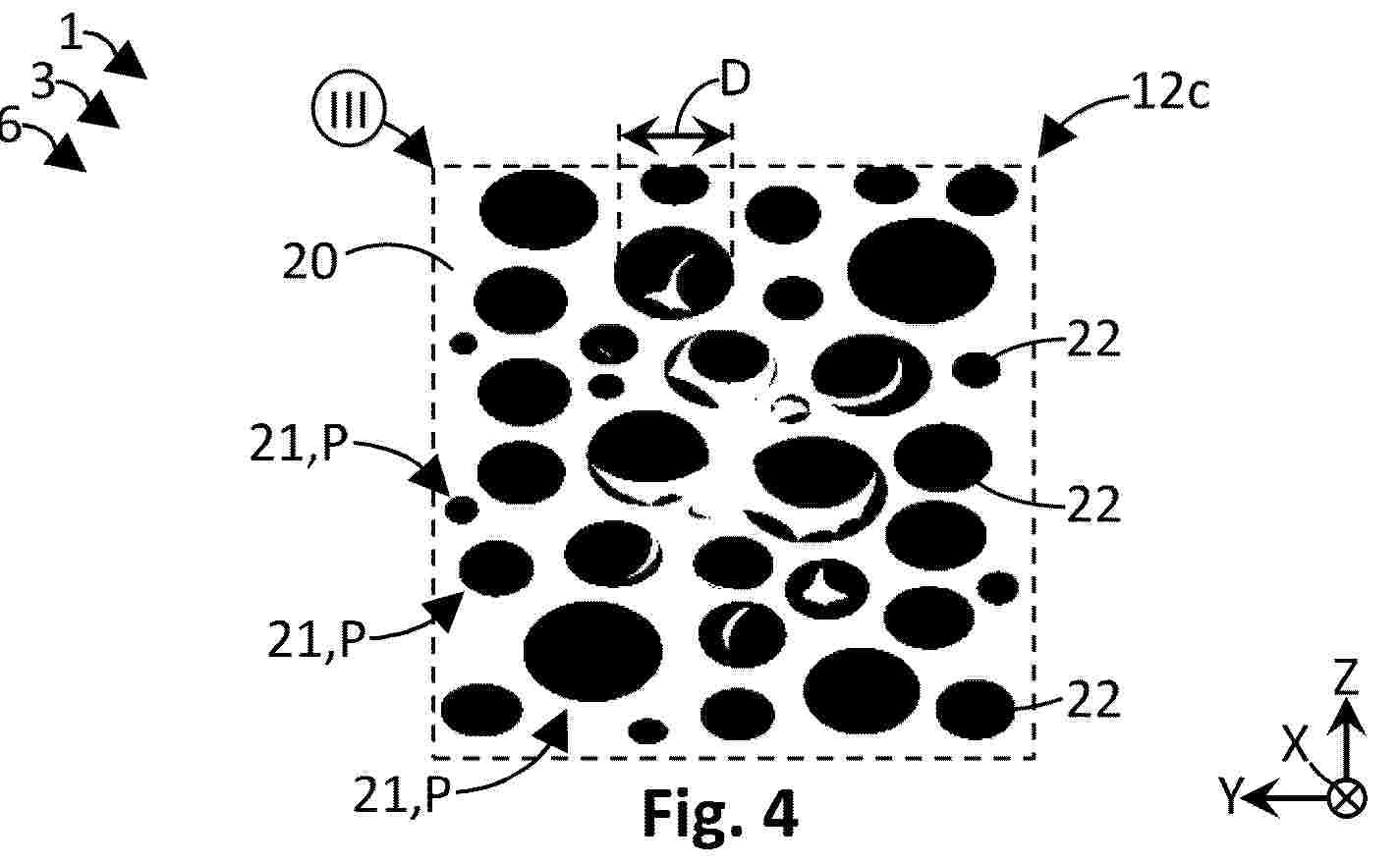
0001 Es werden ein Verfahren zur Herstellung von Katalysatorschichten (12a, 12c) für Brennstoffzellenelemente (8) eines Brennstoffzellenmoduls (6), eine katalysatorbeschichtete Membran (12) für Brennstoffzellenelemente (8) eines Brennstoffzellenmoduls (6), eine Brennstoffzellenanordnung (2) mit einem entsprechenden Brennstoffzellenmodul (6), eine Antriebseinheit (4) für ein Fahrzeug (1), insbesondere Luftfahrzeug, mit einer entsprechenden Brennstoffzellenanordnung (6), und ein entsprechendes Fahrzeug (1), insbesondere Luftfahrzeug, vorgeschlagen, wobei das Verfahren folgende Schritte umfasst: Bereitstellen einer Substratstruktur (20) mit Mikroöffnungen (21) und zumindest abschnittsweises Verfüllen der Mikroöffnungen (21) mit einem Katalysatorstoffgemisch (22), das ein lonomer und eine katalytische Komponente umfasst.
Resumen de: WO2025137171A1
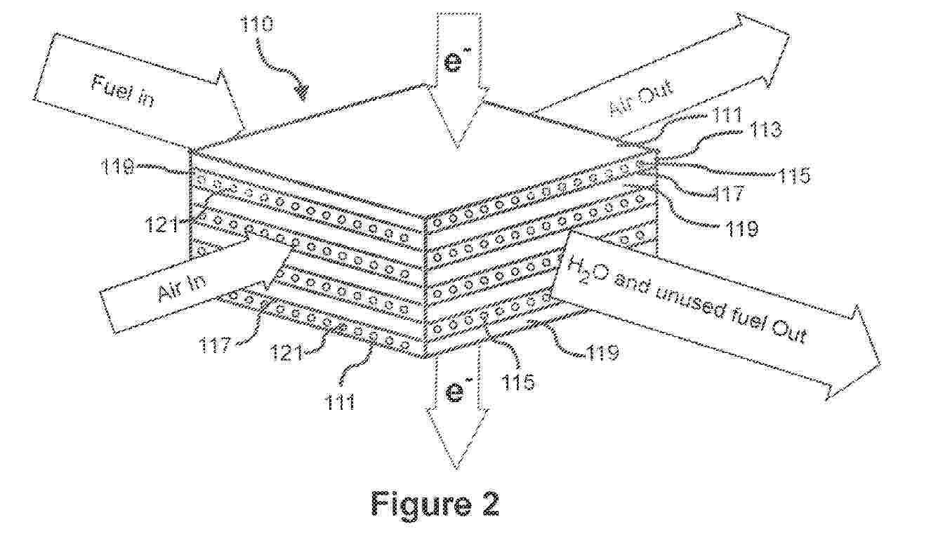
A solid oxide electrochemical reactor cell stack is disclosed that includes a stack of repeating solid electrochemical cells. Each solid oxide electrochemical cell includes a sintered interconnect layer and a sintered anode layer including a first gas distribution network configured to receive an oxidizable fuel. Each cell also includes a sintered electrolyte layer and a sintered cathode layer including a second gas distribution network configured to receive an oxidizing gas. All of the layers of all of the solid oxide electrochemical cells in the stack were simultaneously sintered to form a monolithic solid oxide electrochemical cell stack, having an interconnect at opposite ends. The interconnects, the anodes, the cathodes and the electrolytes each have a CTE, and wherein all CTE's are within 3 pm m 1 K 1 of each other. A method is also disclosed.
Resumen de: EP4814032A1
Provided are an ion conductive compound which exhibits excellent ion conductivity and is useful as an ion exchange material such as an anion exchange membrane, an ion conductive membrane, an electrolyte membrane, a separator, or a water treatment membrane, and a method for preparing the same.
Resumen de: EP4814031A1
0001 Provided are an Ion conductive polymer which exhibits excellent ion conductivity and is useful as an ion exchange material such as an anion exchange membrane, an Ion conductive membrane, an electrolyte membrane, a separator, or a water treatment membrane, and a method for preparing the same.
Resumen de: WO2025111441A1
Provided herein generally are methods and apparatus for the operation of a fuel cell unit or system, or a combustion based device using a variety of different natural gas fuel sources. In certain embodiments, a conduit containing a catalytic bed and an oxygen sensor is used to determine the gas species and their relative concentrations in a natural gas fuel.
Resumen de: WO2025108942A1
The present invention relates to new coolant compositions for cooling systems, the compositions containing at least one polymer that contains at least one polyethylene imine.
Resumen de: WO2025109218A1
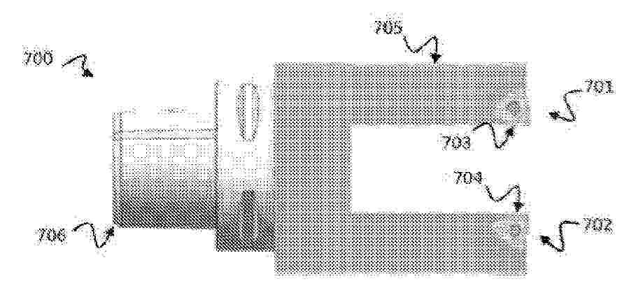
According to a first of its aspects, the invention relates to a milling tool (700) for machining a blank (170) intended to provide certain parts of an electrolyzer stack, for example a bipolar plate (11). It comprises at least two separate milling heads (701, 702) each provided with a cutting tool (703, 704), the milling heads (701, 702) being configured to be operated on either side of the blank (170) to be milled, and a support element (705) provided with two arms for supporting the milling heads (701, 702) and provided with means (706) for coupling to a robot arm.
Resumen de: US20250167271A1
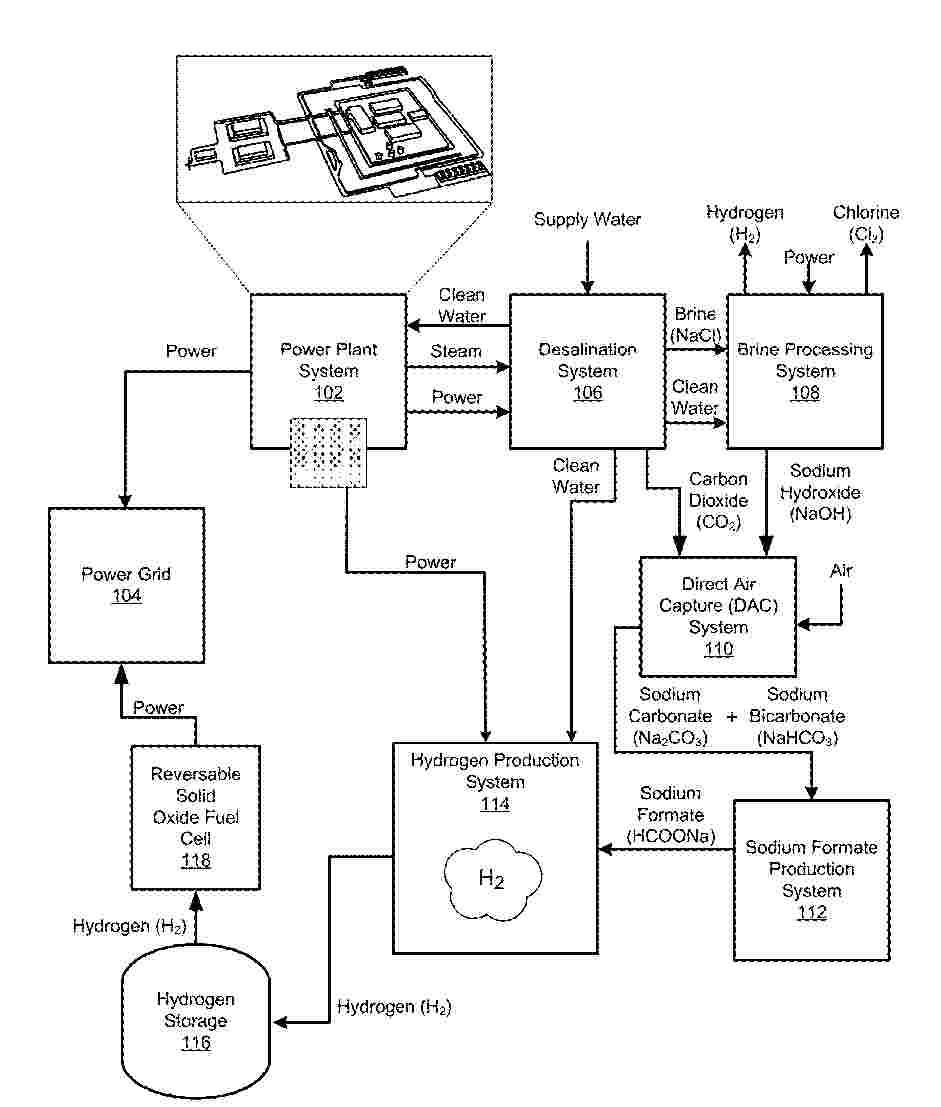
0000 An integrated energy system comprising a power plant including at least one nuclear reactor and electrical power generation system, the at least one nuclear reactor being configured to generate steam, and the electrical power generation system being configured to generate electricity, a desalination system configured to receive at least a portion of the electricity and steam to produce brine, an electrolysis process configured to process the brine into Sodium Hydroxide (NaOH), a Sodium Formate (HCOONa) production process configured to receive the Sodium Hydroxide (NaOH) to produce Sodium Formate (HCOONa), a Hydrogen (H<2>) extraction reactor configured to receive the Sodium Formate (HCOONa) and produce Hydrogen (H<2>), and a fuel cell configured to receive the Hydrogen (H<2>).
Resumen de: EP4815074A1
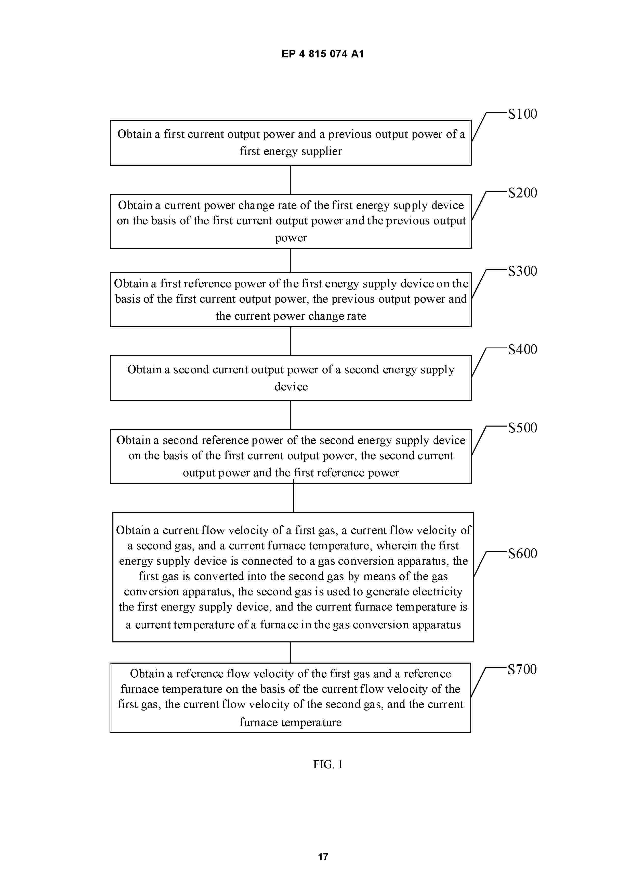
0001 An energy management method and system, a computer device, and a readable storage medium. The energy management method comprises obtaining a first current output power and a previous output power of a first energy supply device; obtaining a current power change rate of the first energy supply device on the basis of the first current output power and the previous output power; obtaining a first reference power of the first energy supply device on the basis of the first current output power, the previous output power and the current power change rate; obtaining a second current output power of a second energy supply device; and obtaining a second reference power of the second energy supply device on the basis of the first current output power, the second current output power and the first reference power; obtaining a current flow velocity of a first gas, a current flow velocity of a second gas, and a current furnace temperature; and obtaining a reference flow velocity of the first gas and a reference furnace temperature on the basis of the current flow velocity of the first gas, the current flow velocity of the second gas, and the current furnace temperature.
Resumen de: EP4815073A1
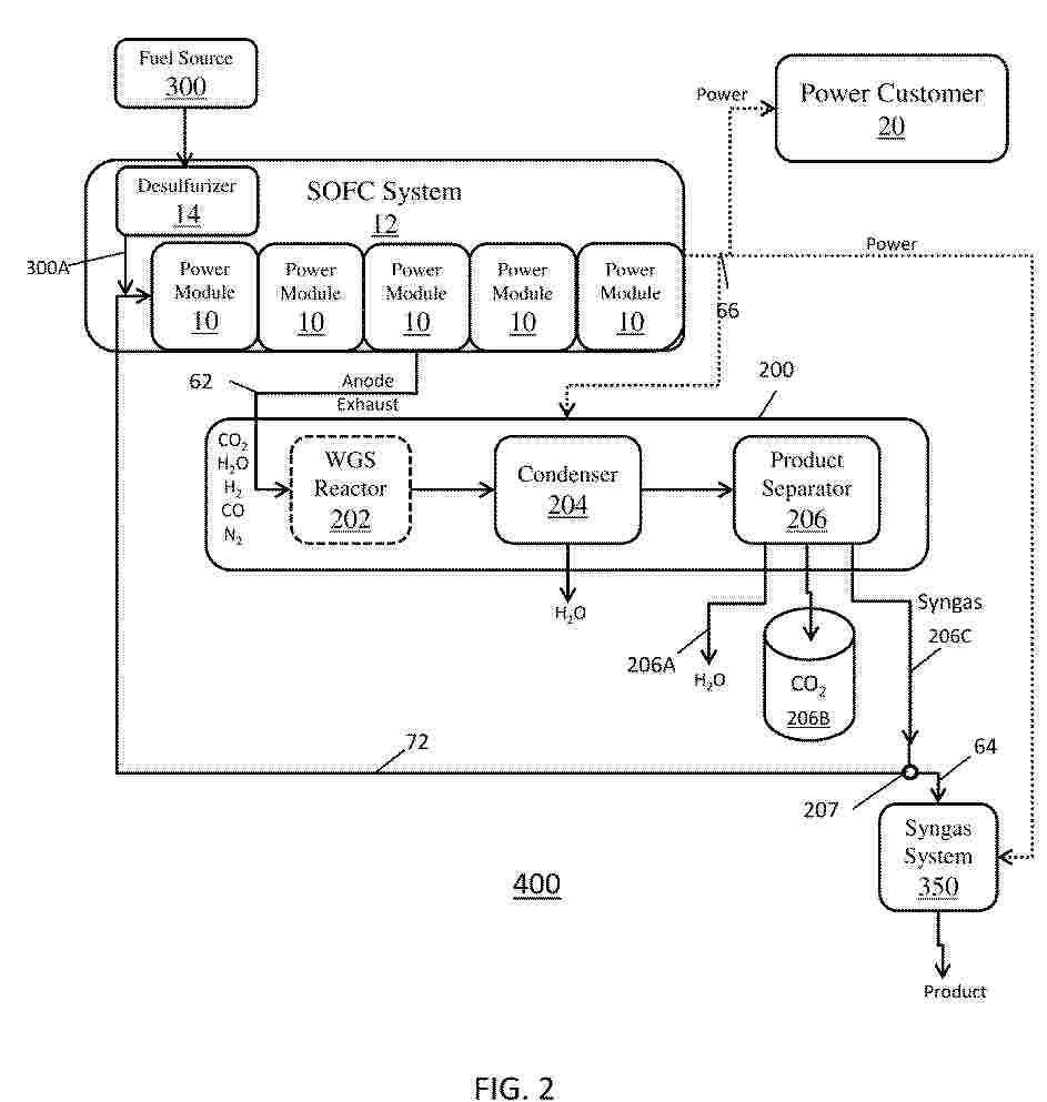
A method includes providing fuel and air to a fuel cell system to generate electric power, an anode exhaust and a cathode exhaust, separating at least a portion of water and carbon dioxide from the anode exhaust received from the fuel cell system to form syngas containing at least 50 molar percent of a mixture of hydrogen and carbon monoxide, recycling a first portion of the syngas output from the exhaust processing system to the fuel cell system, and providing a second portion of the syngas output from the exhaust processing system to a syngas system to generate a product using the syngas.
Resumen de: CN122842425A
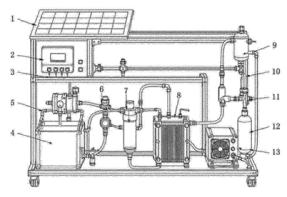
本发明提供了一种太阳能电解水制氢与燃料电池发电一体化实验装置,属于新能源教学实验设备技术领域。该装置包括承载框架以及集成于其上的太阳能发电供电模块、净水与循环供水模块、电解槽模块、气体分离与净化模块、储氢缓冲模块和燃料电池发电模块。太阳能发电供电模块为电解槽提供电力,净水与循环供水模块通过回流管路与电解槽形成水路闭环循环,电解槽产生的氢气依次经气体分离与净化模块、储氢缓冲模块后供给燃料电池发电模块,实现“光—电—氢—电”完整能量转换链条的直观演示。本发明将太阳能制氢与燃料电池发电高度集成于同一平台,具有结构紧凑、集成度高、运行稳定、教学直观的优点,适用于新能源教学演示与科普展示等场景。
Resumen de: CN224817120U
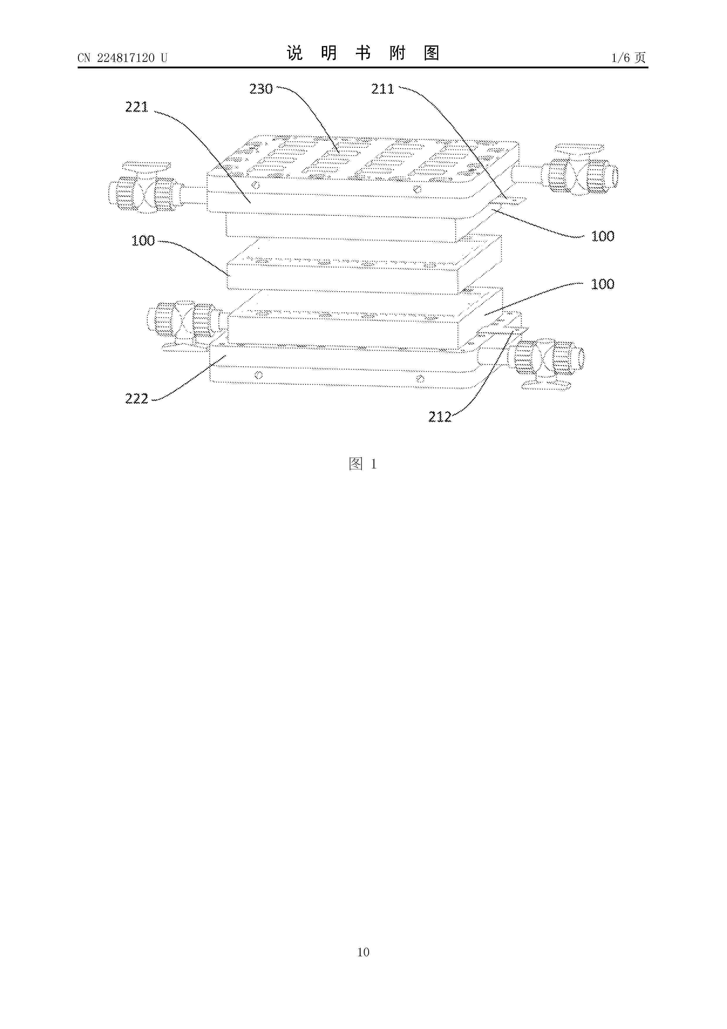
本申请公开了一种液流电池电堆,涉及液流电池技术领域,包括:至少两个电堆子模块、设置于相邻电堆子模块之间的第一密封件以及用于施加轴向压紧力的紧固组件。每个电堆子模块包含至少两个单电池,电堆子模块内部的单电池间通过焊接形成永久性密封连接,确保了优良的密封性和结构强度;而电堆子模块之间则通过第一密封件和紧固组件形成可拆卸的密封连接。本申请通过这种模块化设计,将永久性的焊接密封与可拆卸的机械密封相结合,有效解决了现有技术中电堆密封可靠性与后期可维护性难以兼顾的矛盾。当某个电堆子模块故障时,仅需进行局部更换,降低了维修难度和成本,同时提高了生产装配效率和电堆的整体使用寿命。
Resumen de: CN224817116U
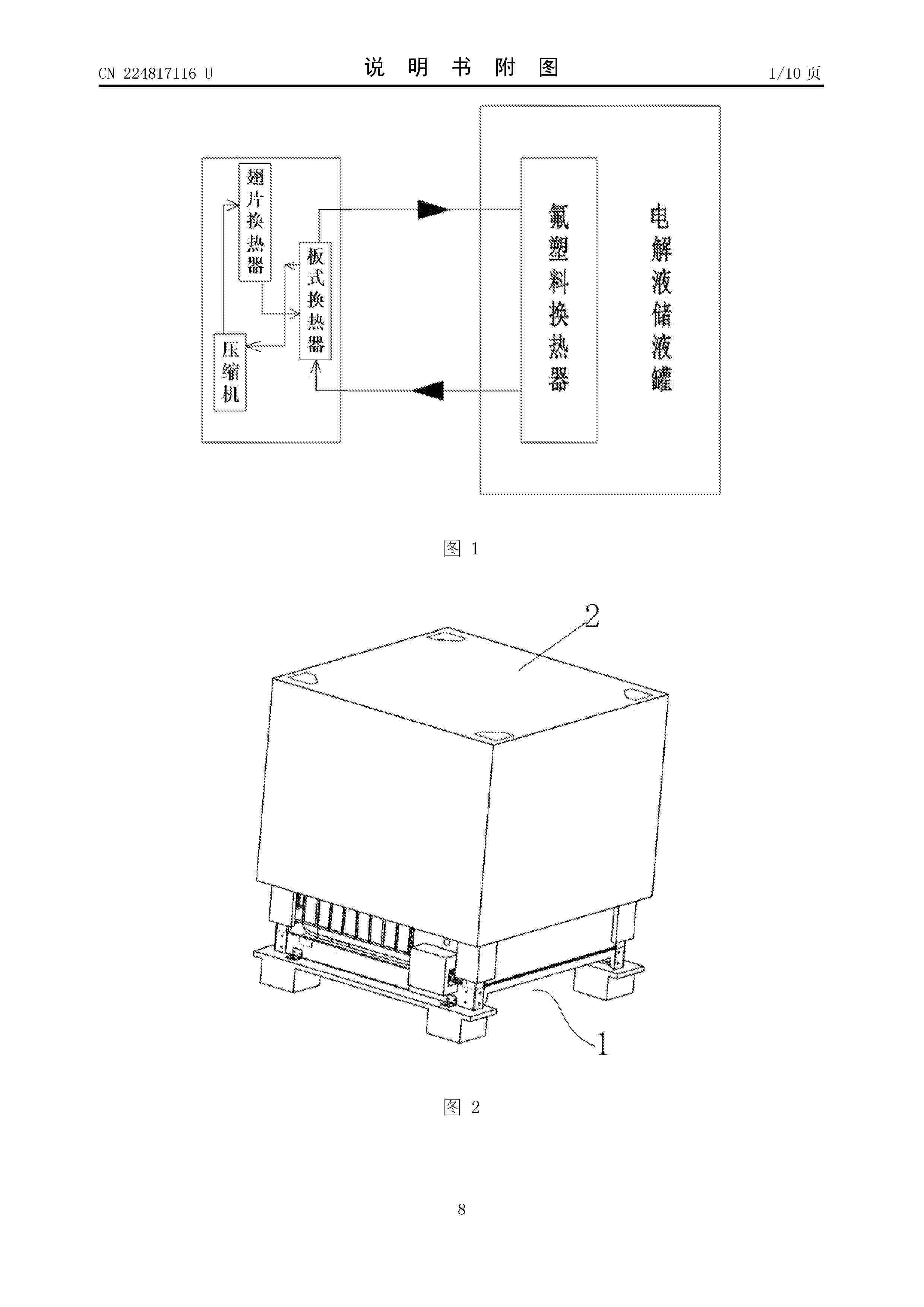
本实用新型涉及电解液冷却设备技术领域,具体为一种直冷机组装置。包括柜体,柜体顶部设有散热风机,柜体内部设有压缩机、冷凝器,压缩机连接有将制冷剂回流至压缩机的吸气管路,冷凝器连接有将制冷剂导入至冷凝器的排气管路,冷凝器出口连接有将制冷剂从冷凝器导出的冷液管路;吸气管路连接压缩机入口,排气管路连接压缩机出口与冷凝器;其中,冷液管路中的制冷剂吸收电解液热量后通过吸气管路回流至压缩机;吸气管路、排气管路和冷液管路均包含有U形管路。本实用新型设备流出的低温制冷剂在钛管换热器内直接与高温电解液进行热交换,代替传统间接水冷为电解液降温的方式,采用直冷的方式对电解液降温。热传递效率较高,电解液降温速度也更快。
Resumen de: CN224817113U
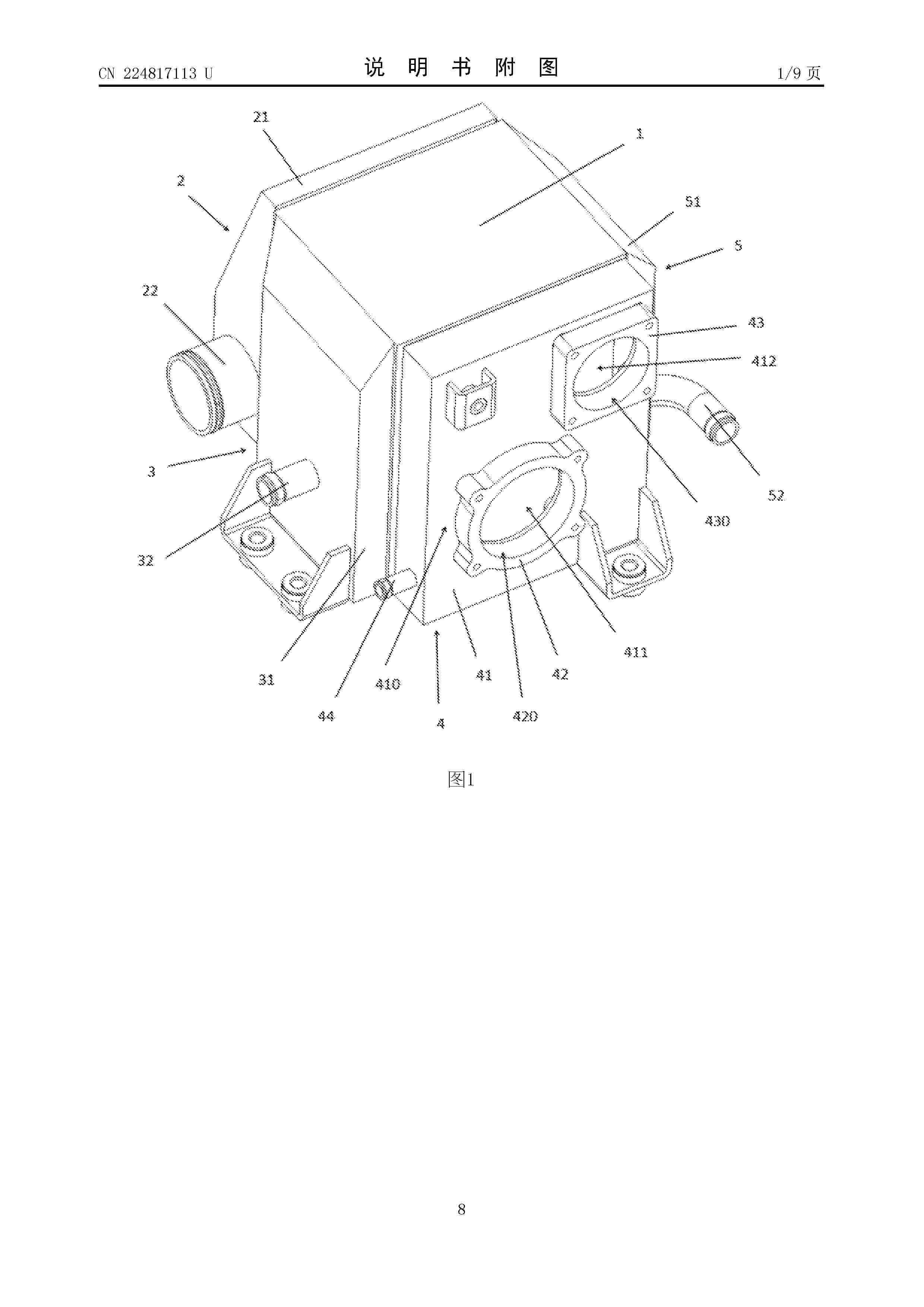
本实用新型涉及一种氢燃料电池用水空中冷器,包括:芯体;第一气封头组件,包括第一气封头本体、进气管道,所述进气管道安装在所述第一气封头本体上;所述第一气封头本体安装在所述芯体上;第二气封头组件,包括第二气封头本体、第一出气接头、第二出气接头,所述第一出气接头、所述第二出气接头安装在所述第二气封头本体上,所述第二气封头本体安装在所述芯体上;第一水封头组件,包括第一水封头本体、进水管道,所述进水管道安装在所述第一水封头本体上,所述第一水封头组件安装在所述芯体上;第二水封头组件,包括第二水封头本体、出水管道,所述出水管道安装在所述第二水封头本体上,所述第二水封头本体安装在所述芯体上。
Resumen de: WO2025172495A1
A layer system (300) and a method and a vacuum arrangement (400) for producing the layer system are disclosed, wherein the layer system (300) has: a carrier plate (102), which has one or more than one metal layer and is designed to provide at least one fluid flow channel (104, 106); and two carbon layers (302, 304) on the carrier plate (102), between which the one or more than one metal layer is arranged and which differ from one another in a resistance of the contact resistance (ICR) to electrochemical corrosion.
Resumen de: GB2636801A
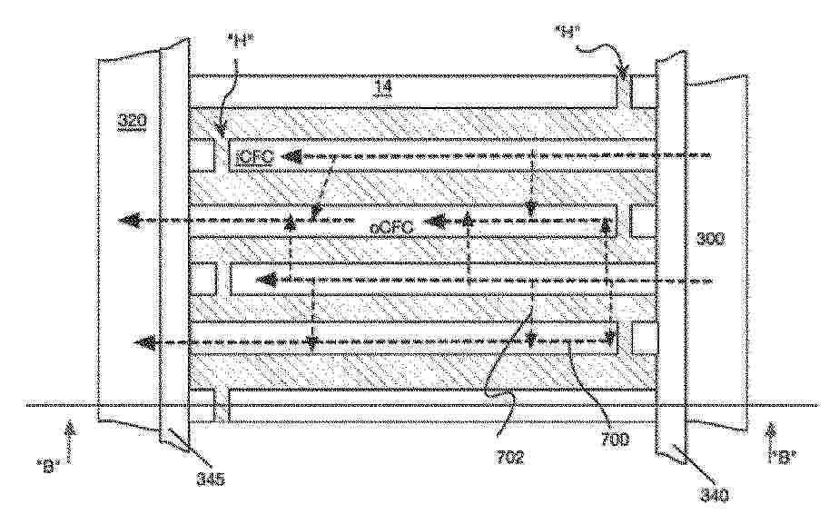
A bipolar plate for a fuel cell assembly has a bipolar frame configured with two reverse image faces of different function comprising; anode flow channels formed of a first portion AFC fluidly connected to second portion AFC’ regardless of gap G. The anode flow channels are fluidly connected to first anode flow passage 330 and second anode flow passage 335. The gap in each anode flow channel is positioned at least 85% downstream from one of the first and second anode flow passages. A cathode field (14, Figure 5C) has inlet cathode flow channels (iCFC, Figure 5C) open and fluidly connected to first cathode fluid passage (340, Figure 5C) but blocked from second cathode fluid passage (345, Figure 5C) via humps (H, Figure 5C); and outlet cathode flow channels (oCFC, Figure 5C) blocked by humps from the first cathode flow passage but open and fluidly connected to the second cathode flow passage. A first end of the bipolar frame includes at least one air inlet, at least one water inlet, and at least one hydrogen outlet; whilst a second end includes: at least one cathode fluid outlet, and at least one hydrogen inlet.
Resumen de: WO2025210347A1
A catalyst-coated membrane for a water electrolyser is provided. The catalyst-coated membrane comprises a polymer electrolyte membrane with an anode catalyst layer on a first side of the membrane. The anode catalyst layer comprises an oxygen evolution reaction catalyst containing at least one noble metal at a loading of the oxygen evolution reaction catalyst, based on the noble metal content, of less than or equal to 0.6 mg/cm2. The polymer electrolyte membrane comprises a membrane layer comprising dispersed platinum group metal-containing nanoparticles, a nanoparticle stabilising agent and an ion-conducting polymer.
Resumen de: CN118913569A
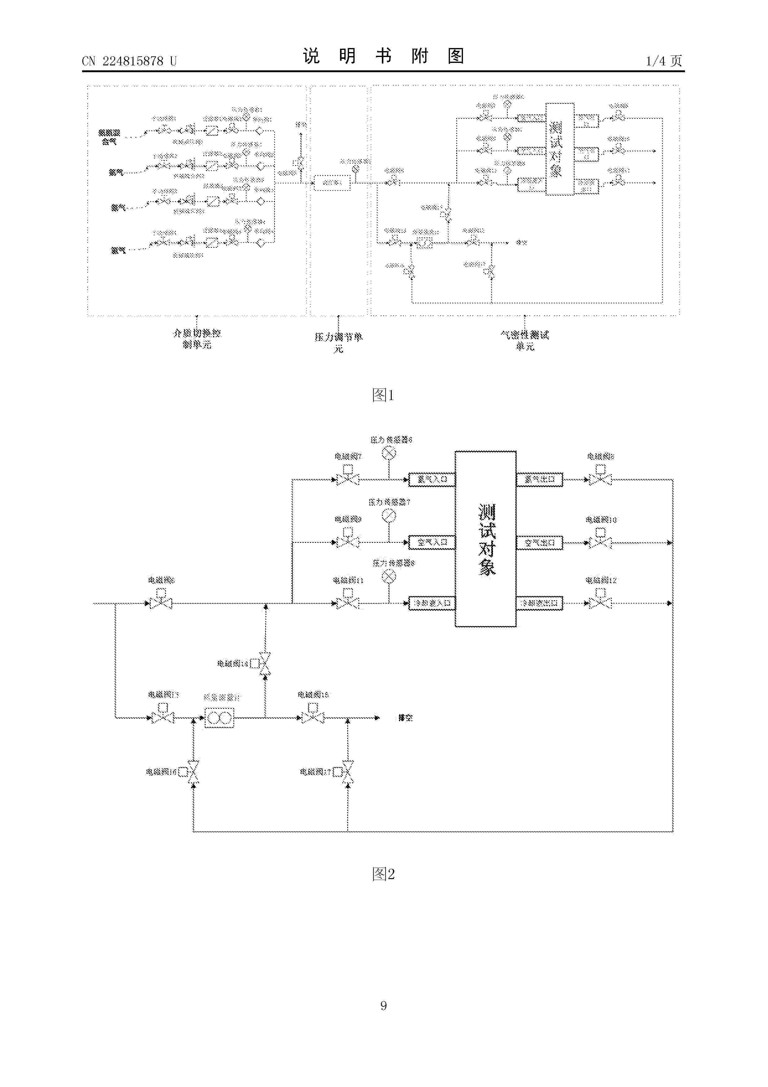
The invention relates to the technical field of fuel cell testing, in particular to an automatic testing method and device for the airtightness of a fuel cell stack, and the method comprises the steps: selecting a testing medium gas source required by automatic testing according to a testing demand, and setting a pressure regulating parameter and testing duration of the automatic testing; determining and inputting the opening/closing state of each electromagnetic valve in the scheme in the pressure regulating process; determining and inputting the opening/closing state of each electromagnetic valve after the test data is recorded; and generating a test scheme according to the related data of the automatic test, and issuing the test scheme to the PLC for automatic execution. According to the invention, all test requirements can be met, and the test is automatically completed by generating the test scheme, so that the test is accurate, rapid and stable, the complicated manual operation is greatly reduced, and the test error caused by improper manual operation or inaccurate operation is avoided.
Nº publicación: CN122847444A 29/09/2026
Solicitante:
丰田自动车株式会社
Resumen de: WO2025187346A1
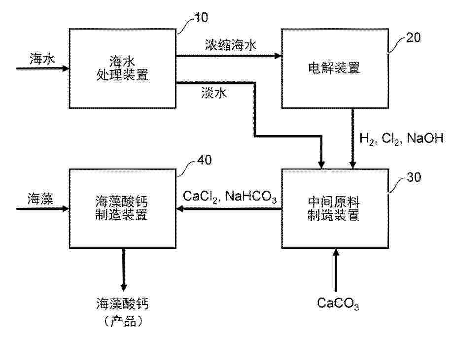
A marine plant system according to an aspect of the present disclosure comprises: a seawater treatment device (10) that separates seawater into fresh water and concentrated seawater; an electrolysis device (20) that electrolyzes the concentrated seawater separated by the seawater treatment device (10); an intermediate raw material production device (30) that uses the fresh water separated by the seawater treatment device (10) and hydrogen gas, chlorine gas, and sodium hydroxide generated by the electrolysis device (20) to produce calcium chloride and sodium hydrogen carbonate from calcium carbonate; and a calcium alginate production device (40) that uses the calcium chloride and sodium hydrogen carbonate produced by the intermediate raw material production device (30) to extract alginic acid from seaweed collected from the sea and produce calcium alginate.
 BOPI
BOPI
 Sede Electrónica