Si deseas distinguir tus productos, servicios o ambos de los de otra empresa, es posible que necesites una marca o nombre comercial. Descubre qué son, en qué consiste su procedimiento de registro y qué implica.

Información sobre los plazos de presentación de solicitudes de transformación de marcas de la Unión Europea en marca nacional española. Más información


Si tienes un nuevo dispositivo, producto o procedimiento que resuelva un problema técnico o tenga una ventaja práctica, existen distintas formas de protegerlo en España y en otros países. Descubre cómo hacerlo.

¿Tu innovación reside en la estética, la ornamentación o la apariencia de tu producto? Protégela mediante un diseño industrial. Descubre qué derechos confiere el registro y cómo realizar la tramitación.

Las indicaciones geográficas protegen el nombre de un producto originario de una zona geográfica, a la cual le debe una determinada calidad, reputación u otra característica. Descubre qué son, en qué consiste su procedimiento de registro y qué beneficios conceden.

Las patentes publicadas en todo el mundo son una valiosa fuente de información científica, técnica y comercial.

Si eres emprendedor/a o una empresa y quieres potenciar y mejorar la rentabilidad de tu negocio protegiendo de forma adecuada los activos intangibles de tu organización, en este espacio encontrarás lo necesario.


 1094
resultados
1094
resultados
 Última actualización
19/07/2026 [07:13:00]
Última actualización
19/07/2026 [07:13:00]


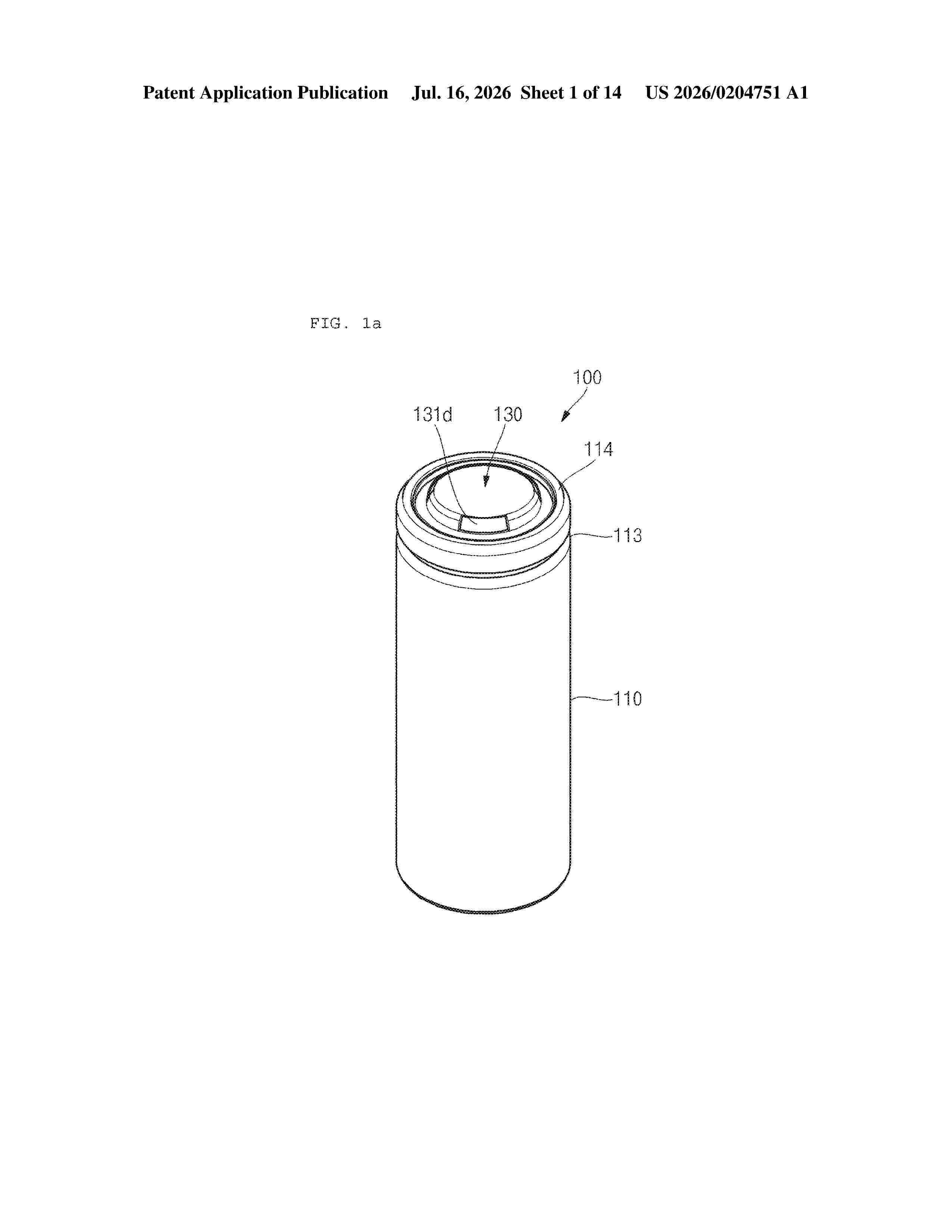
Resumen de: US20260204751A1
0000 The present invention relates to an electrode assembly and a secondary battery including same. A jelly-roll-type electrode assembly comprises a positive electrode non-coated portion formed on a positive electrode plate, and a negative electrode non-coated portion formed on a negative electrode plate. The negative electrode non-coated portion includes a first negative electrode non-coated portion formed between the front end and the rear end of the negative electrode plate in the winding direction, and a second negative electrode non-coated portion formed at the rear end of the negative electrode plate. A negative electrode tab is disposed in the first negative electrode non-coated portion.

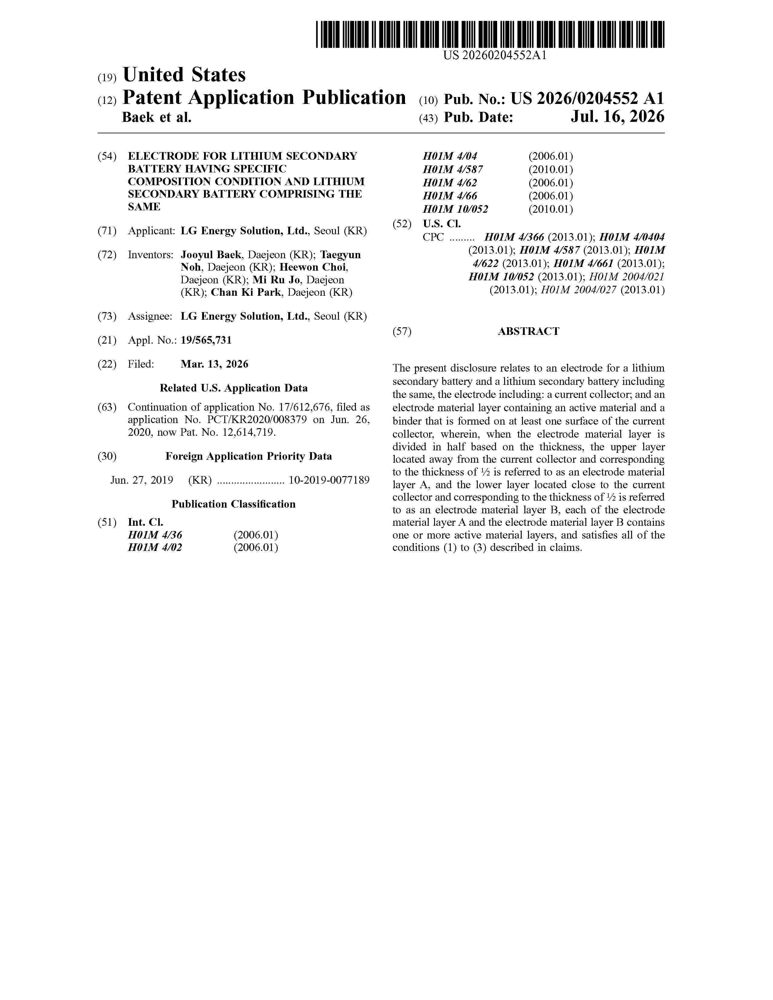
Resumen de: US20260204552A1
The present disclosure relates to an electrode for a lithium secondary battery and a lithium secondary battery including the same, the electrode including: a current collector; and an electrode material layer containing an active material and a binder that is formed on at least one surface of the current collector, wherein, when the electrode material layer is divided in half based on the thickness, the upper layer located away from the current collector and corresponding to the thickness of ½ is referred to as an electrode material layer A, and the lower layer located close to the current collector and corresponding to the thickness of ½ is referred to as an electrode material layer B, each of the electrode material layer A and the electrode material layer B contains one or more active material layers, and satisfies all of the conditions (1) to (3) described in claims.
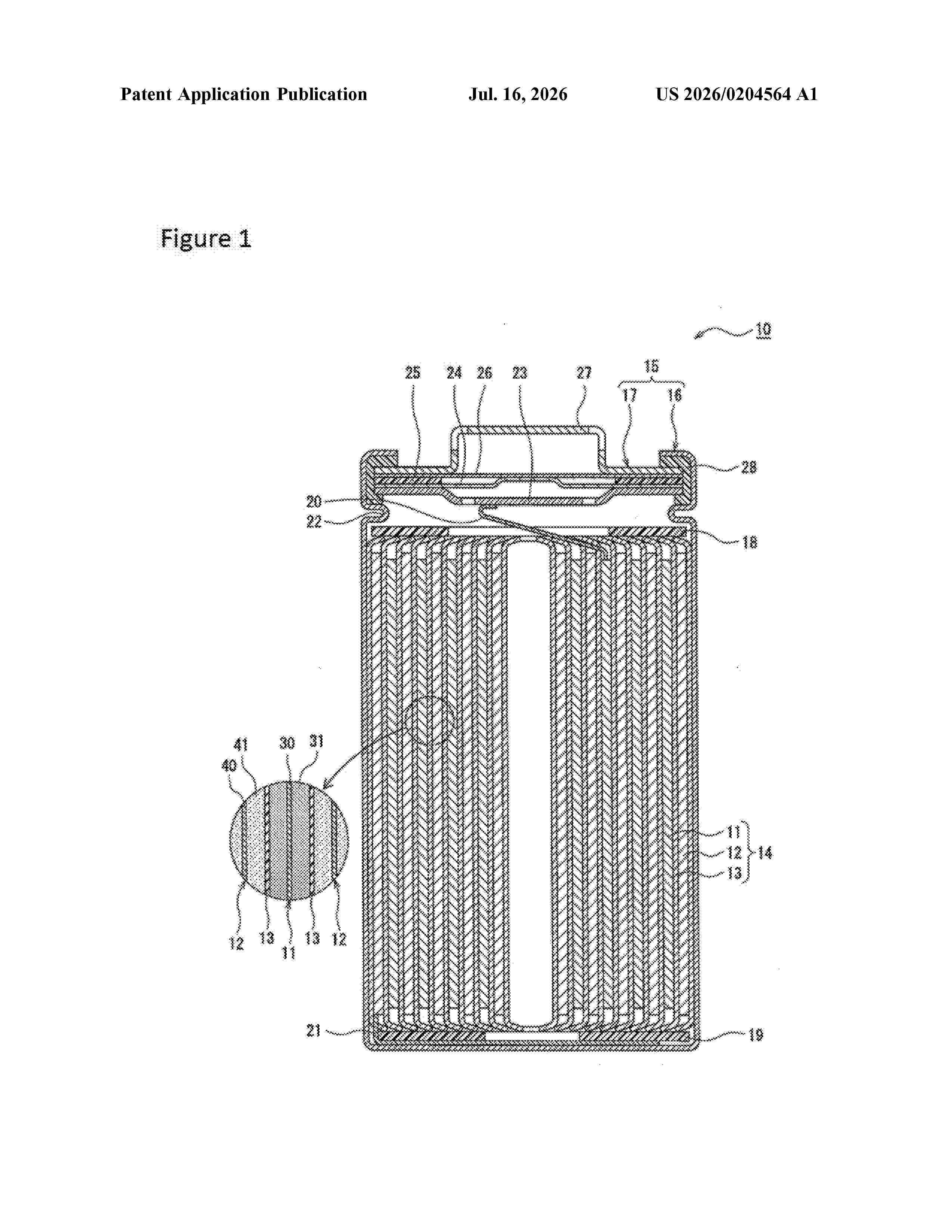
Resumen de: US20260204564A1
Provided is a cathode active material for a non-aqueous-electrolyte secondary battery, the cathode active material containing a lithium composite oxide that has a layered structure containing a Li layer and that is represented by general formula LiaNiαAlβCoγMδSrxO2−w (in the formula, 0.95
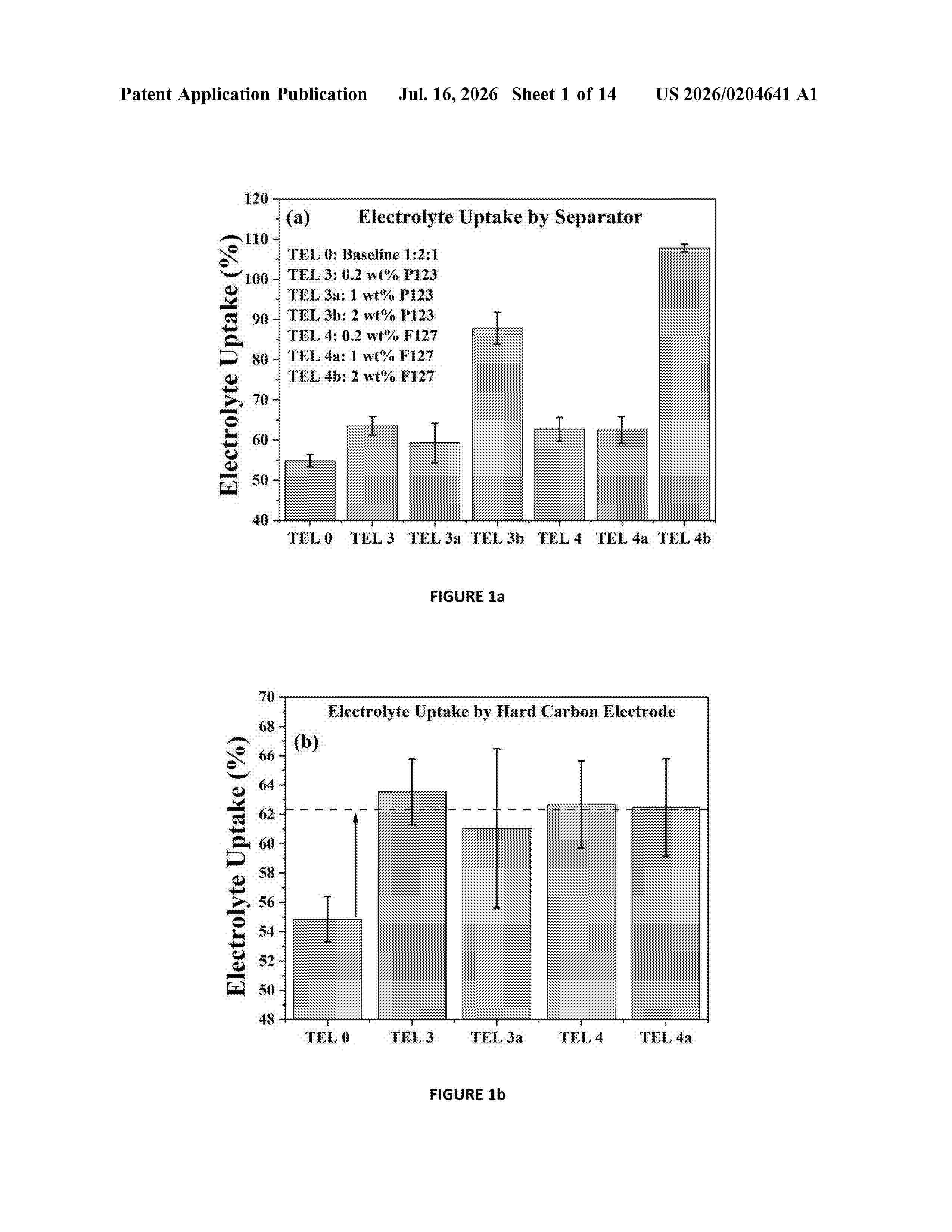
Resumen de: US20260204641A1
The invention provides novel non-aqueous electrolyte compositions comprising: a) one or more sodium-containing compounds; andb) a solvent system which comprises: i) a first solvent component which comprises one or more organo carbonate-based solvents; andii) a second solvent component which comprises one or more surfactants in an amount of >0.5 to ≤10% by weight of the solvent system,
Resumen de: US20260204671A1
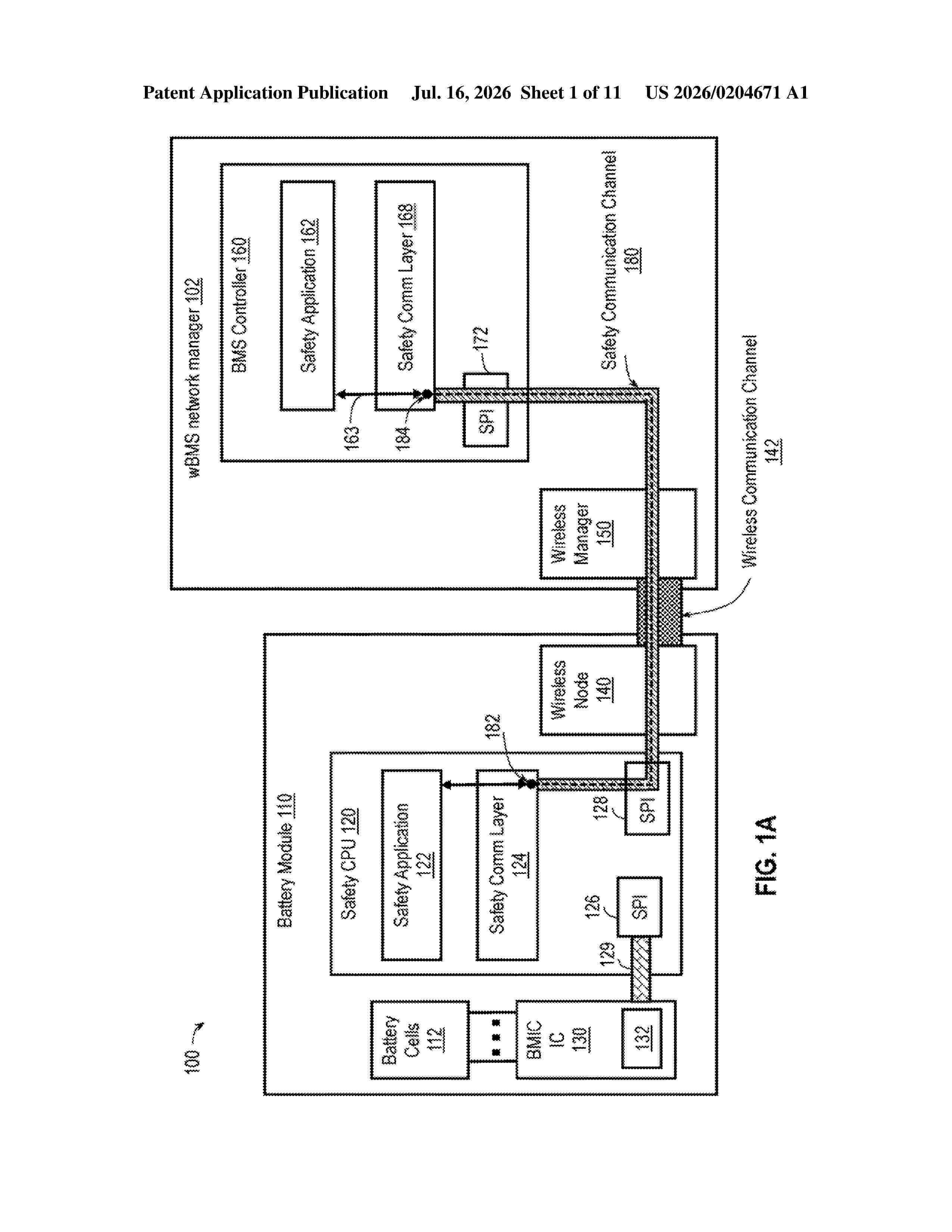
0000 Systems, devices, and methods related to wireless battery management system (wBMS) are provided. For example, a wBMS network manager comprises a memory to store a list of hardware identifiers (IDs), wherein each hardware ID in the list is associated with a respective one of a plurality of battery modules; and mapped, based on a predetermined mapping, to a different one of a plurality of source IDs; an interface to receive, from a remote battery module, a packet including a source ID and a hardware ID associated with the remote battery module; and one or more processing units to search, using the source ID in the received packet and the predetermined mapping, for a first hardware ID from the list of hardware IDs; and authenticating the remote battery module based on a comparison of the hardware ID in the received packet to the first hardware ID from the list.
Resumen de: US20260200750A1
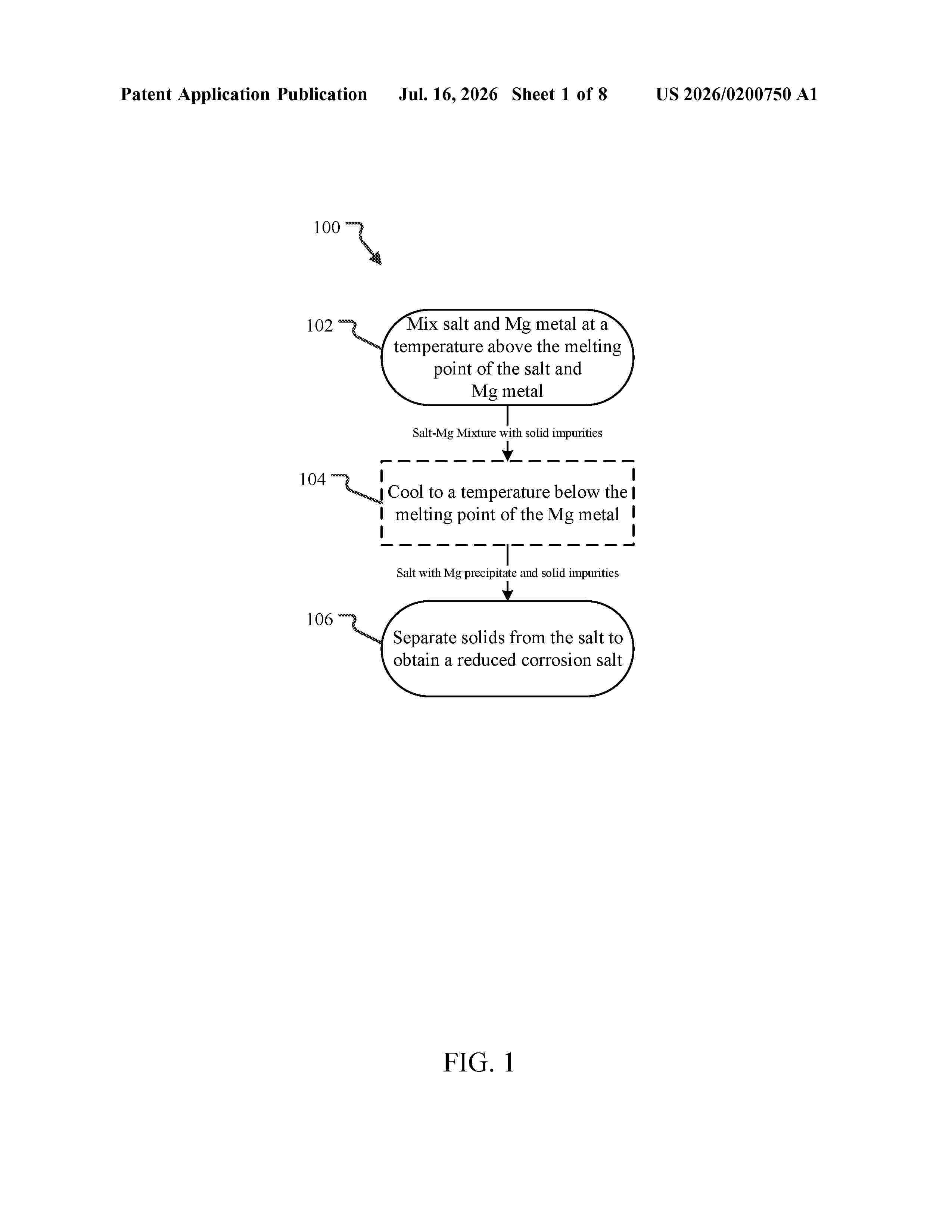
This document describes a method for reducing the corrosivity of certain magnesium salts. The salt product resulting from the method exhibits reduced corrosion of steels that come into contact with the salt relative to salt compositions that are not so treated. This makes such treated salts more efficient coolant salts as they will require less equipment replacement over time. The method uses magnesium metal to reduce unwanted impurities in the salts the reduced impurities are then removed as either gas or precipitate from the now purified salt. Without being bound to one particular theory, it is believed that the reduction of the level of impurities in the salt results in a salt with substantially reduced corrosiveness to steel.
Resumen de: US20260204934A1
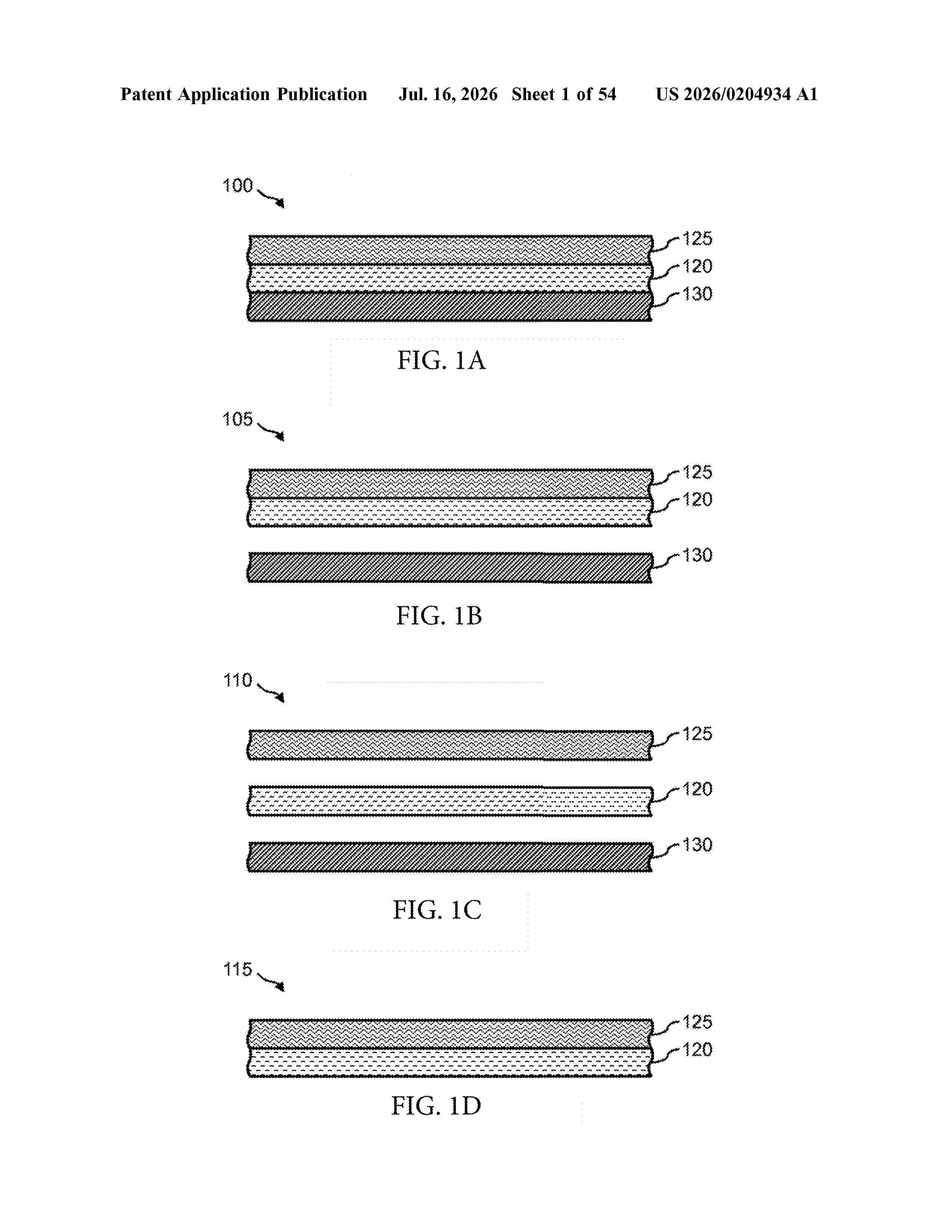
0000 Systems, methods, and articles for a portable power case are disclosed. The portable power case is comprised of at least one battery and at least one PCB. The portable power case has at least one USB port and at least two access ports, at least two leads, or at least one access port and at least one lead. The portable power case is operable to supply power to an amplifier, a radio, a wearable battery, a mobile phone, and a tablet. The portable power case is operable to be charged using solar panels, vehicle batteries, AC adapters, non-rechargeable batteries, and generators. 0000 The portable power case provides for modularity that allows the user to disassemble and selectively remove the batteries installed within the portable power case housing.
Resumen de: US20260204748A1
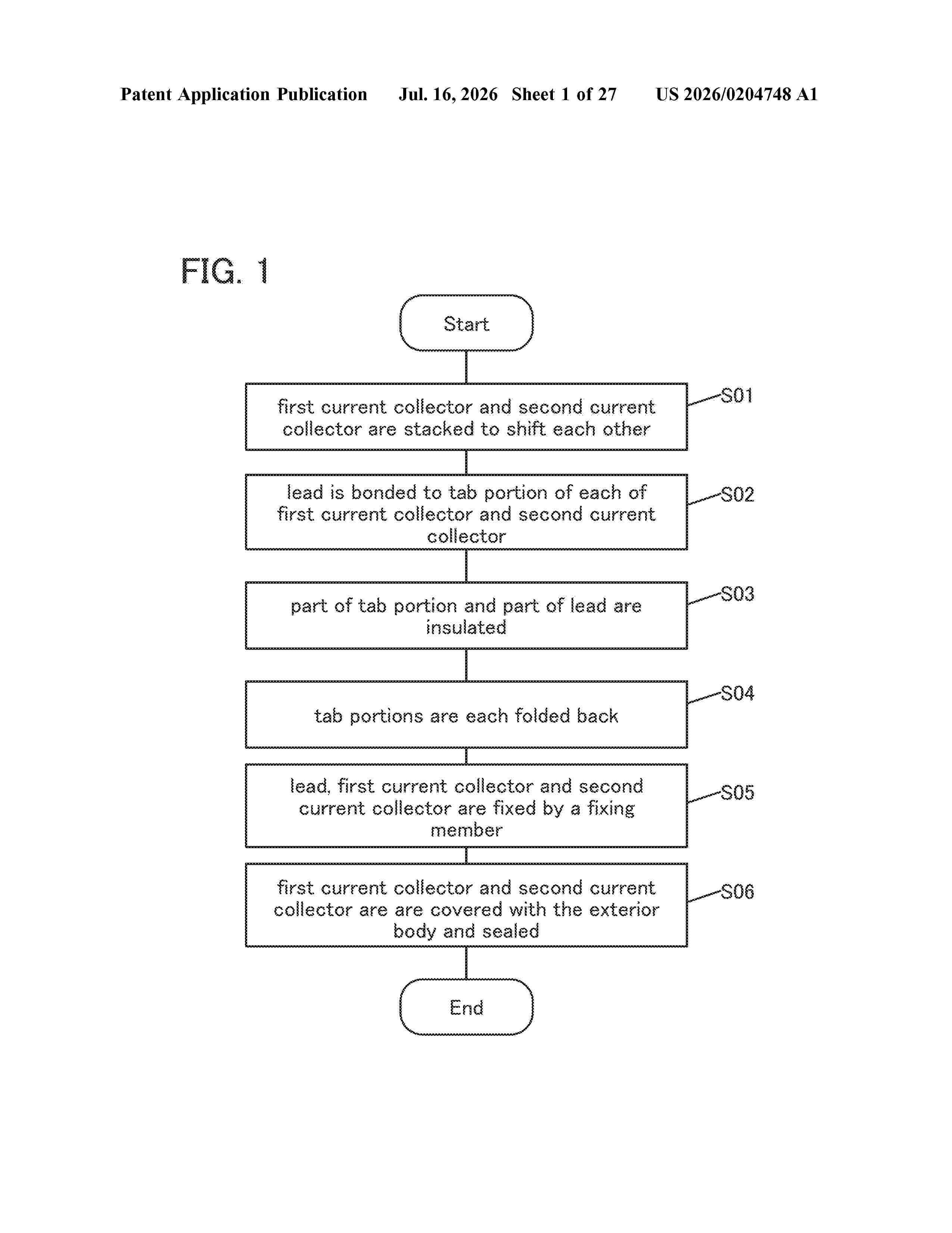
0000 To provide a battery capable of changing in shape safely. To provide a battery capable of repeatedly bent. The battery includes a first lead, a second lead, a first current collector, and a second current collector. The first current collector includes a first portion bonded to the first lead and a second portion coated with a first active material. The second current collector includes a third portion bonded to the second lead and a fourth portion coated with a second active material. The first lead, the second portion, and the fourth portion overlap with each other in a portion. The second lead, the second portion, and the fourth portion overlap with each other in a portion.
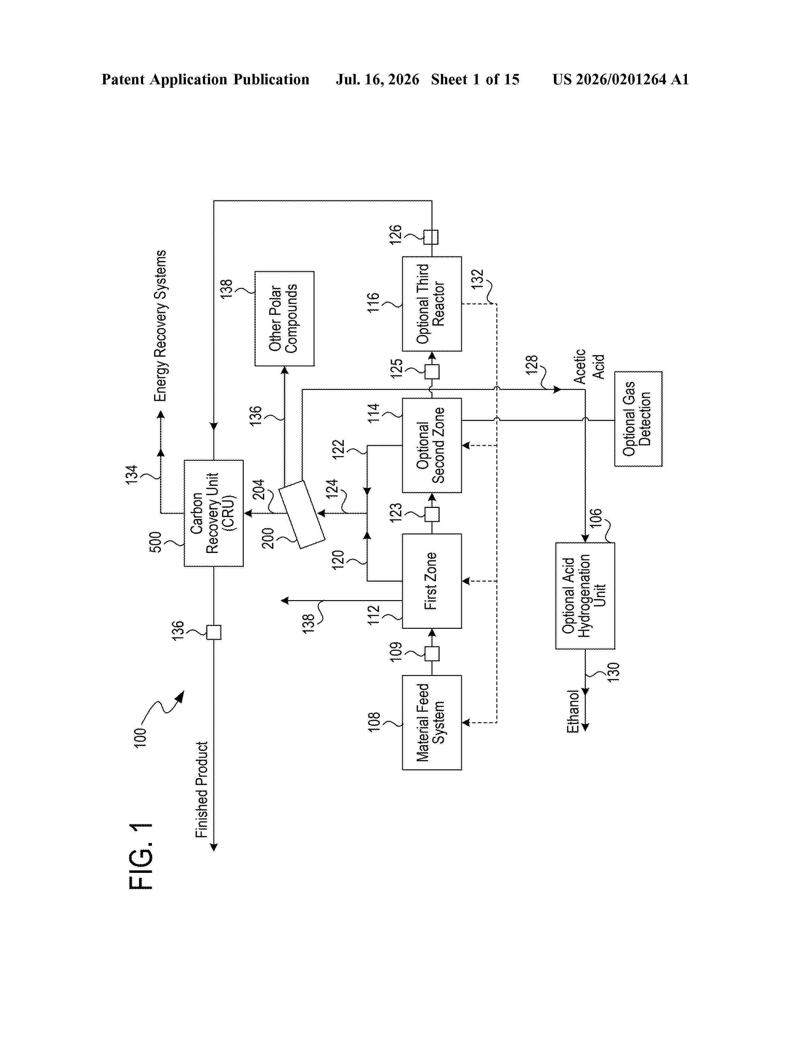
Resumen de: US20260201264A1
0000 This invention provides processes and systems for converting biomass into high carbon biogenic reagents that are suitable for a variety of commercial applications. Some embodiments employ pyrolysis in the presence of an inert gas to generate hot pyrolyzed solids, condensable vapors, and non-condensable gases, followed by separation of vapors and gases, and cooling of the hot pyrolyzed solids in the presence of the inert gas. Additives may be introduced during processing or combined with the reagent, or both. The biogenic reagent may include at least 70 wt %, 80 wt %, 90 wt %, 95 wt %, or more total carbon on a dry basis. The biogenic reagent may have an energy content of at least 12,000 Btu/lb, 13,000 Btu/lb, 14,000 Btu/lb, or 14,500 Btu/lb on a dry basis. The biogenic reagent may be formed into fine powders, or structural objects.
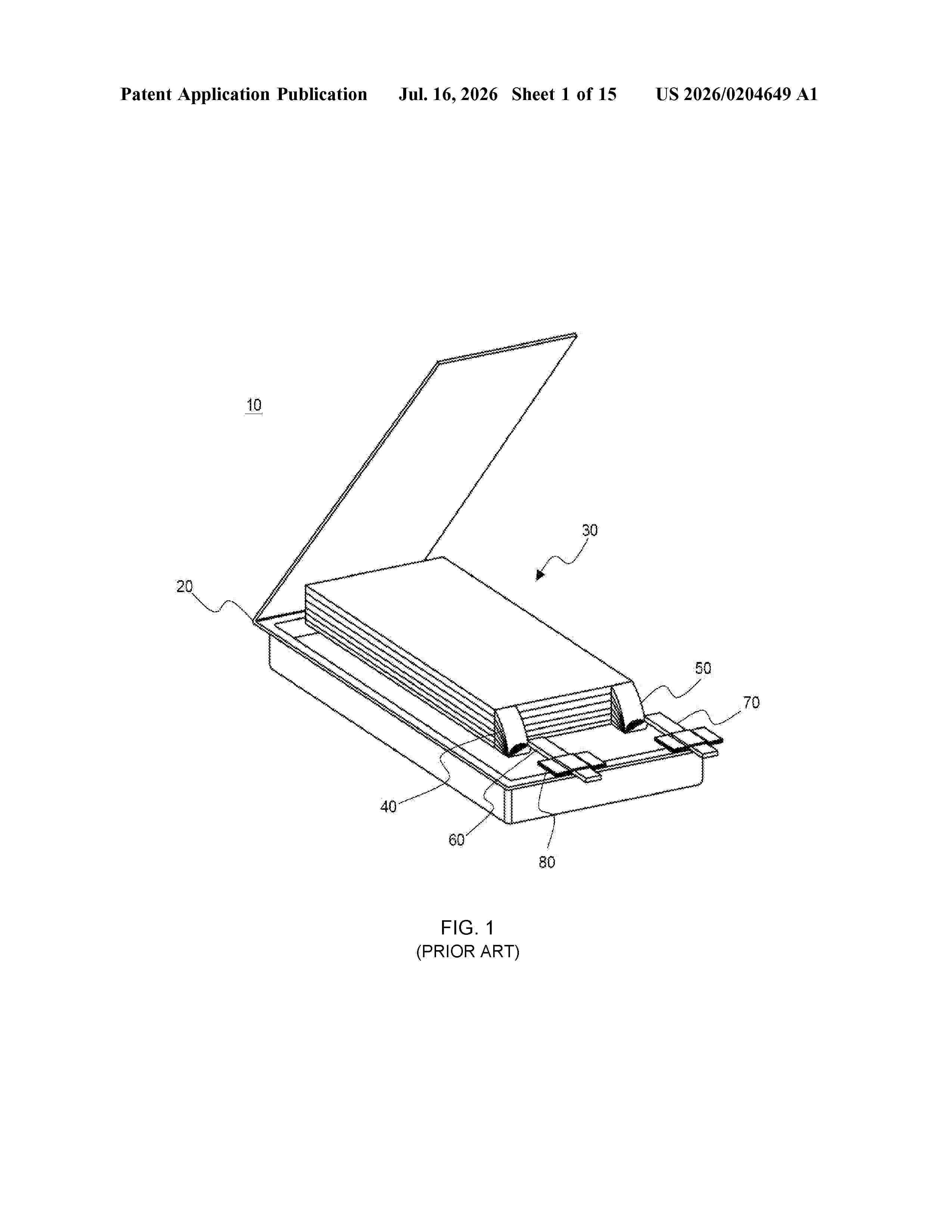
Resumen de: US20260204649A1
The present invention relates to a pouch type case having trimming portions formed on both sides or four corners thereof and a battery pack including the same. The trimming portions are formed on the corners of the pouch type case such that the trimming portions are indented toward an electrode assembly accommodating part to reduce a unit area so as to increase pressure applied to unit cells when a battery pack is assembled, thereby facilitating assembling of the battery pack and increasing cell capacity per unit area. Furthermore, the unit cells can be fixed in the battery pack more stably. The pouch type case reduces the unit area so as to include a relatively large number of cells for pressure applied to the cells when the battery pack is assembled to thereby increase the cell capacity.
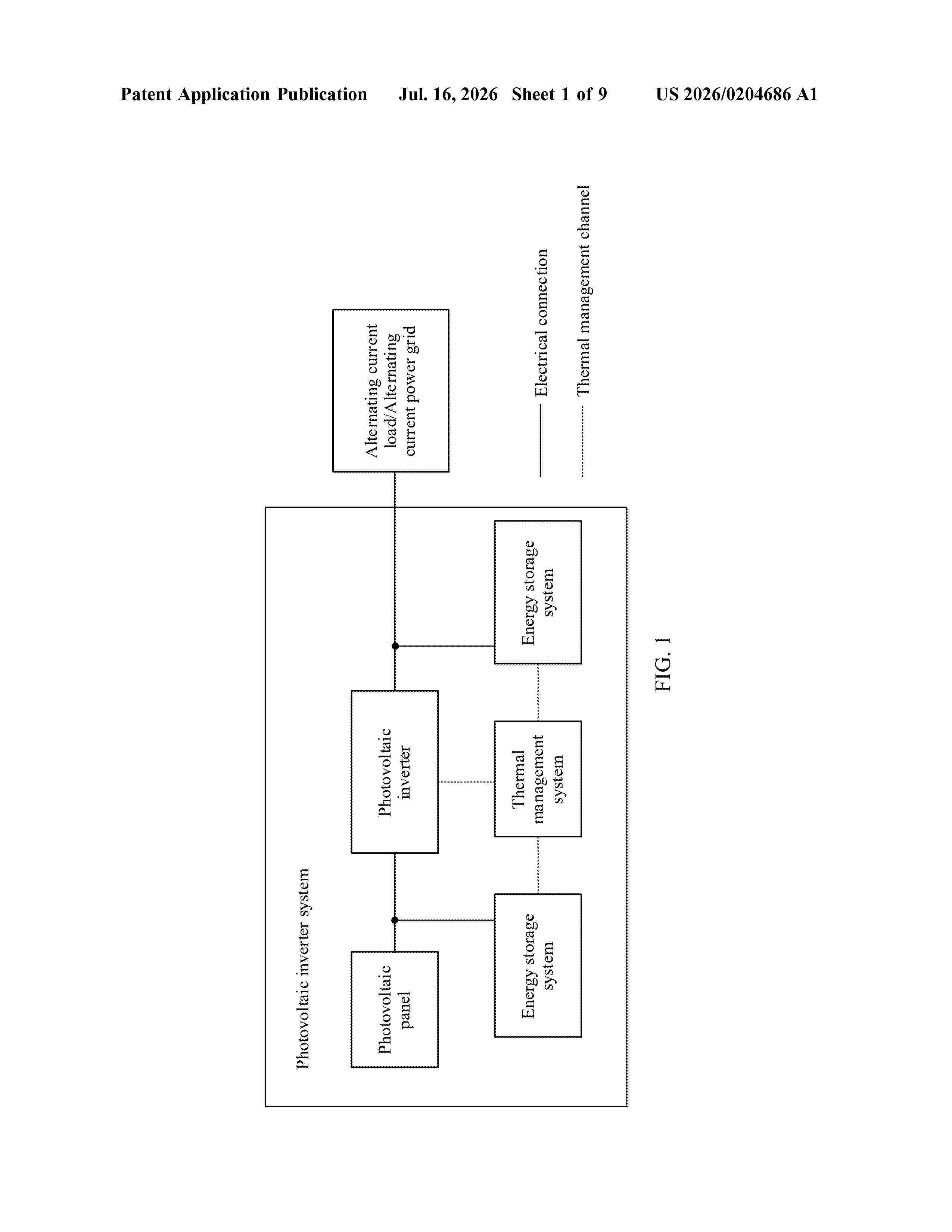
Resumen de: US20260204686A1
This application provides a thermal management system, an energy storage system, and a photovoltaic inverter system. The thermal management system includes a coolant system, a refrigerant system, a heat exchange component, and a load-bearing component. The coolant system includes a coolant flow channel plate and a plurality of coolant end components. The refrigerant system includes a refrigerant flow channel plate and a plurality of refrigerant end components. The heat exchange component is configured to perform heat exchange between the coolant system and the refrigerant system. The plurality of coolant end components and the refrigerant flow channel plate are mounted on a same side of the coolant flow channel plate. The load-bearing component is fastened to the coolant flow channel plate, and the load-bearing component includes a mounting through hole. The components of the thermal management system are integrated. This can reduce mounting and maintenance complexity.
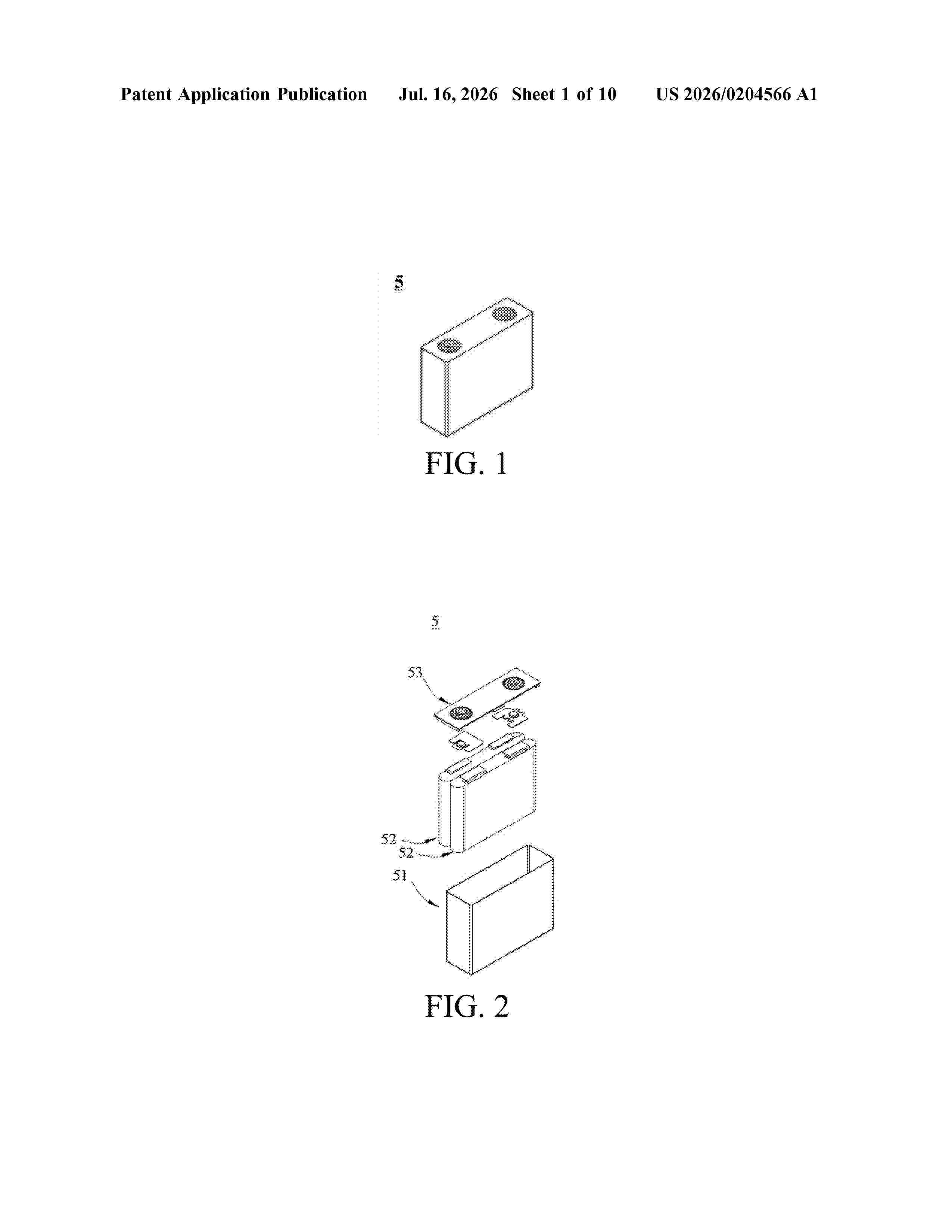
Resumen de: US20260204566A1
A positive electrode active material and a preparation method therefor, a positive electrode plate, a battery, and an electrical apparatus. The positive electrode active material includes a transition metal oxide and a coating layer. The coating layer is coated on at least part of the surface of the transition metal oxide. The coating layer includes a silicon-containing polymer. The silicon-containing polymer is formed by polymerizing a silane monomer derivative containing a first group and polysiloxane containing a second group. The first group is reactive with the second group. The molecular weight of the silane monomer derivative is less than that of the polysiloxane.
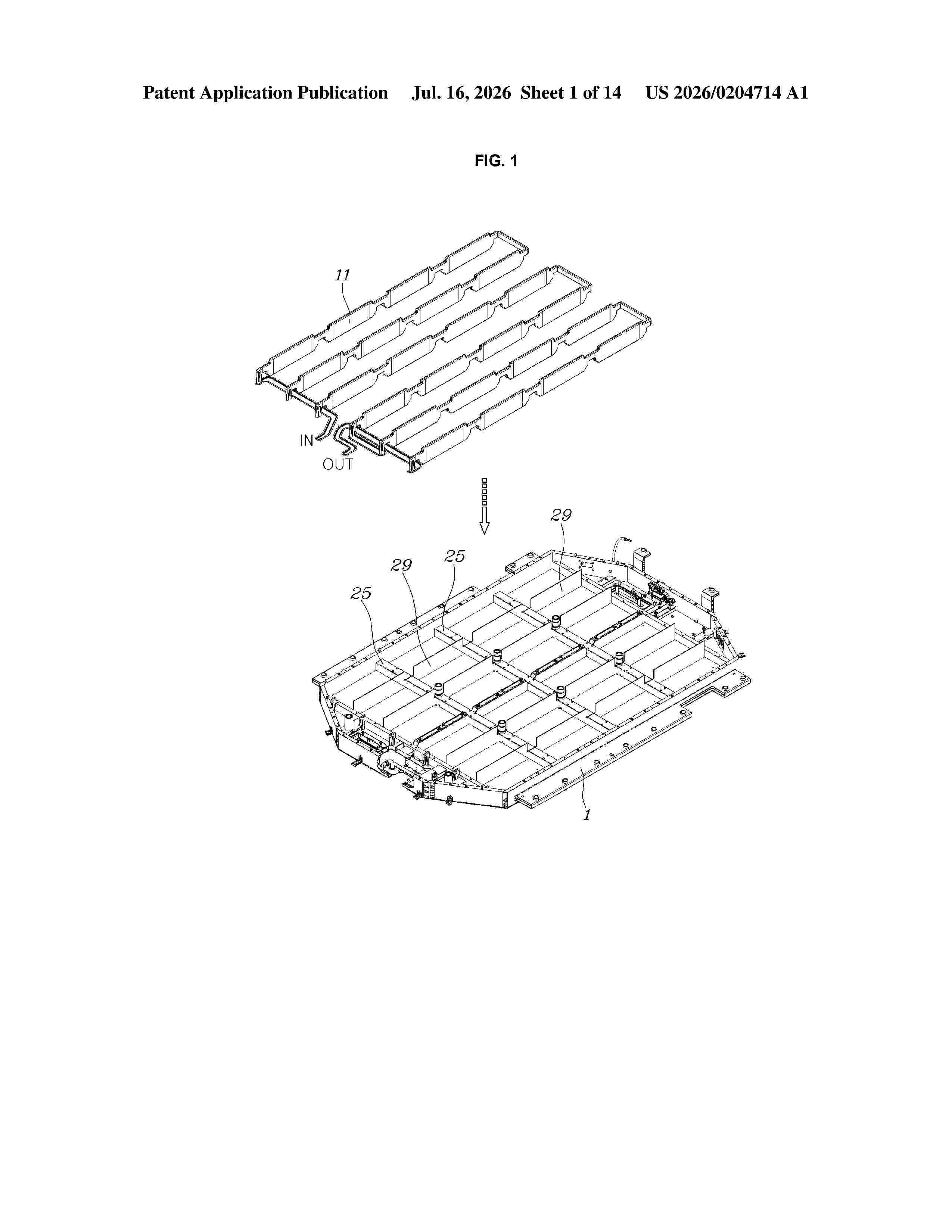
Resumen de: US20260204714A1
0000 A battery pack for a vehicle includes a pack tray with an open upper surface, a plurality of battery cells stacked in a vertical direction on the pack tray, a plurality of sensing blocks, each including a cell bus-bar connected to an electrode of each of the battery cells, and provided on the pack tray, and a pressure plate mounted to press upper surfaces of the stacked battery cells in a downward direction.
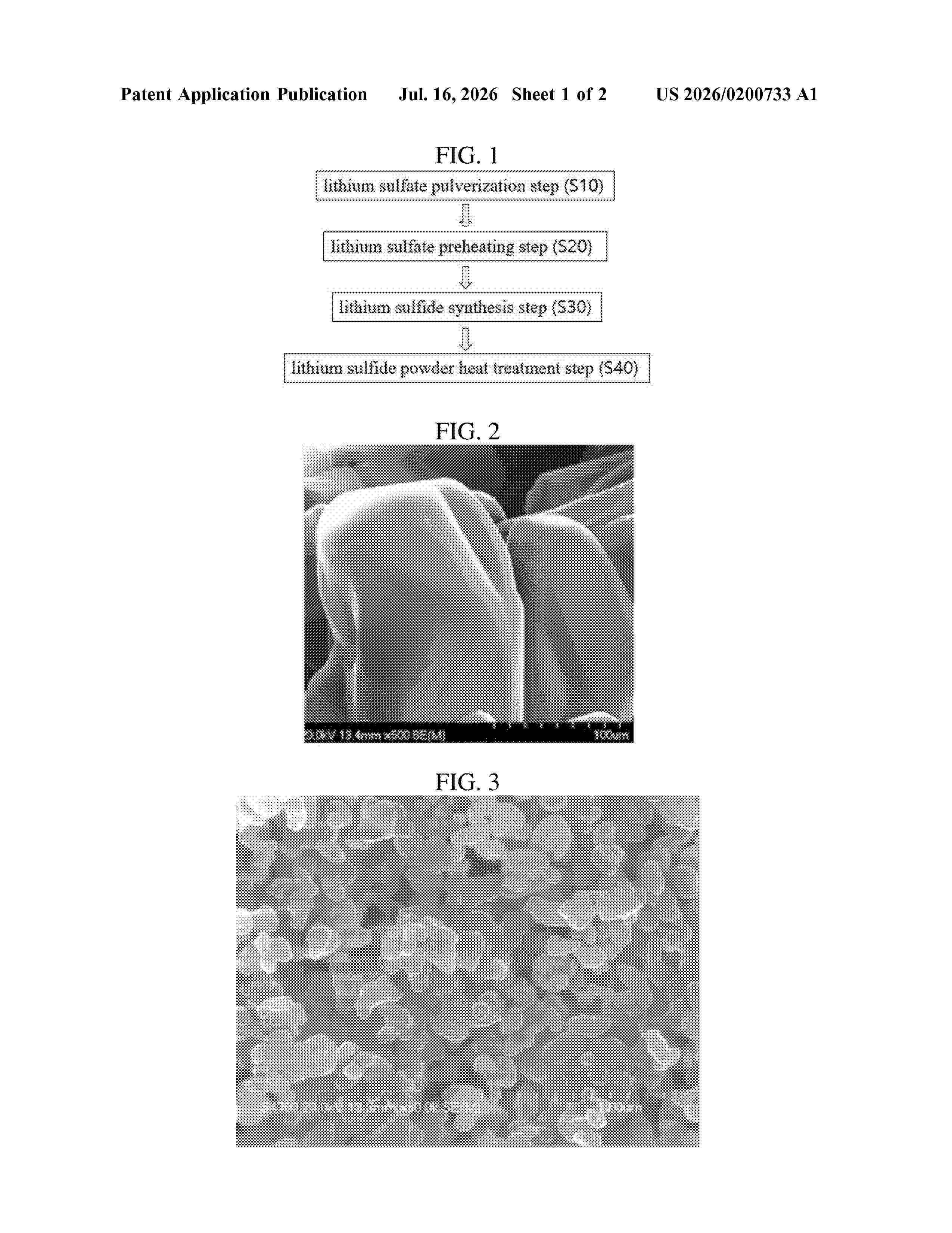
Resumen de: US20260200733A1
The present disclosure discloses a method for producing lithium sulfide, the method comprising a lithium sulfide synthesis step of synthesizing lithium sulfide powder by reacting lithium sulfate powder with a reaction gas containing carbon monoxide, wherein the method further comprising before the lithium sulfide synthesis step, a lithium sulfate pulverization step for pulverizing the lithium sulfate powder into a predetermined size.
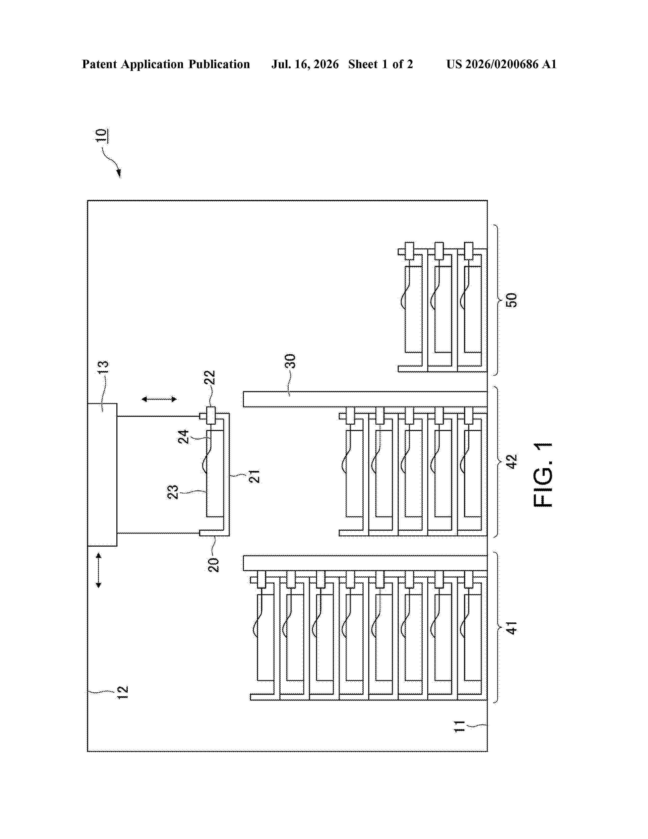
Resumen de: US20260200686A1
Provided is a battery unit storage warehouse including: a skid, which includes a terminal connectable to a battery unit, and is configured to hold the battery unit; a conductor, which is electrically connectable to the battery unit through intermediation of the terminal, when the skid is stacked to store the battery unit; an overhead crane, configured to stack the skid and remove the skid; and a control device, configured to control the overhead crane.
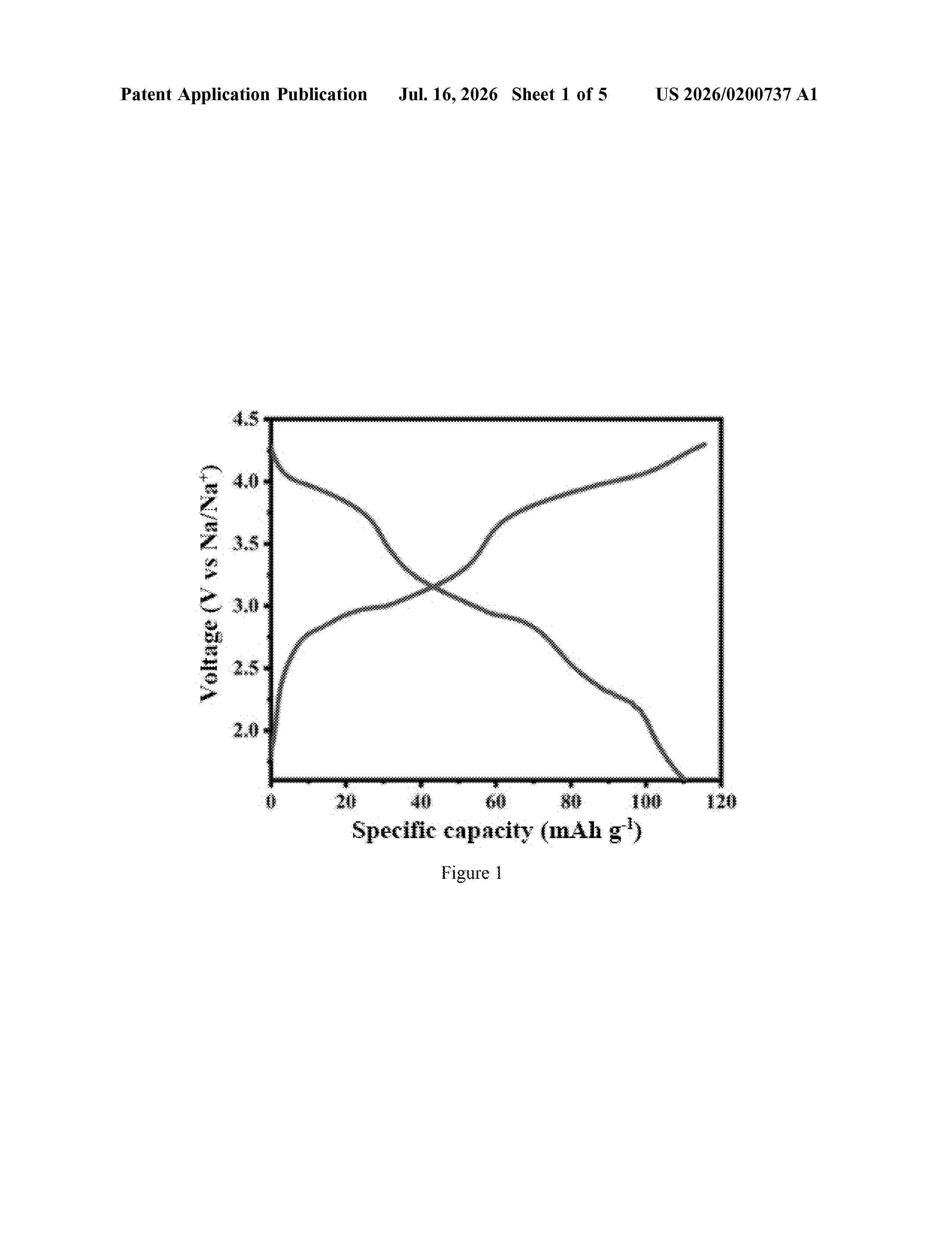
Resumen de: US20260200737A1
0000 A sodium ion battery cathode material and its preparation method and application, belonging to the field of sodium ion battery technology. The sodium ion battery cathode material includes a polyanionic iron-manganese core material and a fast ion conductor layer coated on the outer surface of said polyanionic iron-manganese core material; the polyanionic iron-manganese core material contains iron and manganese, and the iron and manganese are non-uniformly distributed within the polyanionic iron-manganese core material; at the center of the polyanionic iron-manganese core material, the manganese content is higher than the iron content; on the surface layer of the polyanionic iron-manganese core material, the iron content is higher than the manganese content. The non-uniform distribution of iron and manganese can effectively mitigate the risk of structural collapse caused by metal ion migration during cycling; the fast ion conductor coating reduces side reactions caused by electrolyte erosion.
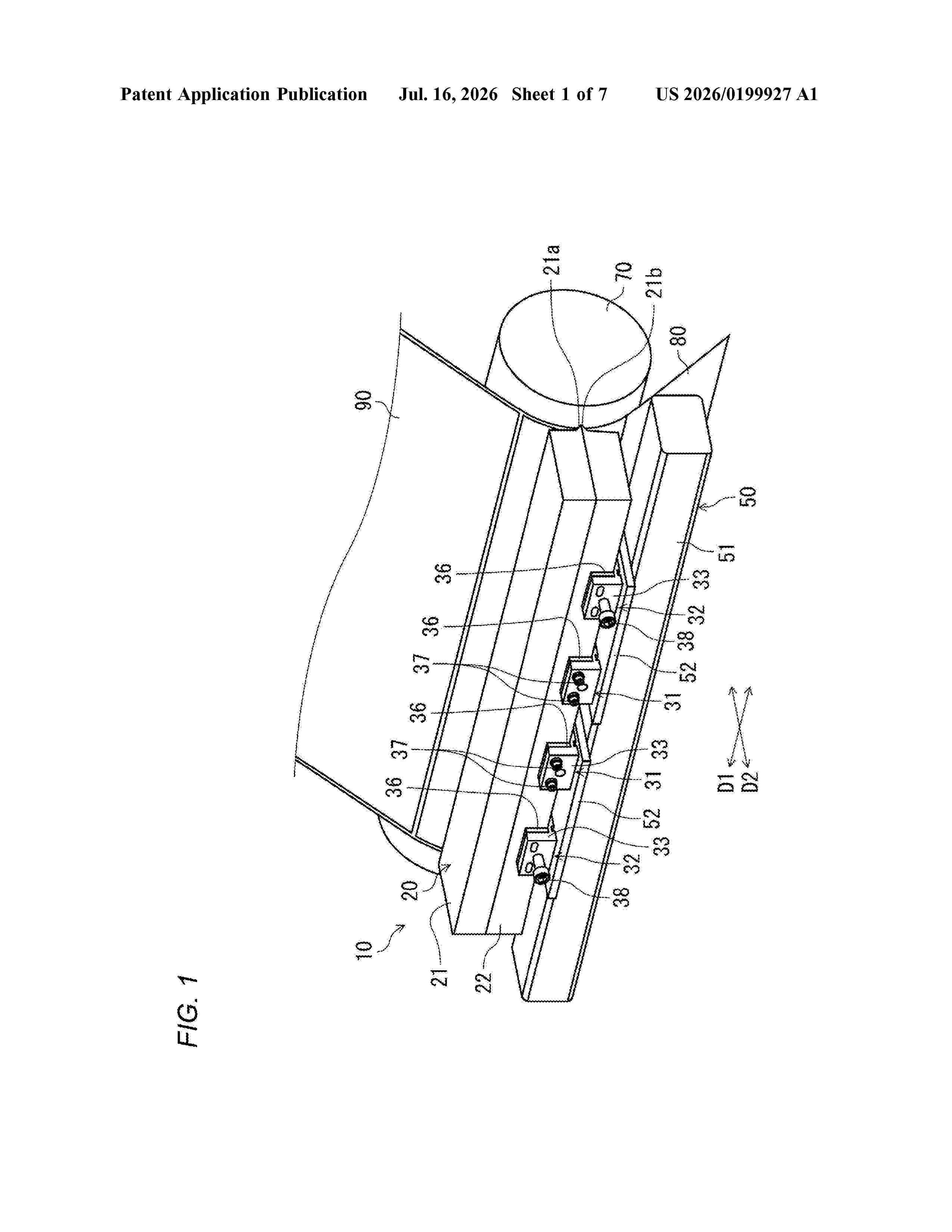
Resumen de: US20260199927A1
A coating device includes: a die head having a discharge port for discharging a slurry to a base material, the discharge port extending in a first horizontal direction; and a plurality of functional units spaced apart from each other in the first horizontal direction. Each of the functional units can be switched to exhibit either one of a fixing function for fixing the die head to a base and a deforming function for deforming the die head in a second horizontal direction orthogonal to the first horizontal direction. Some of the functional units are configured to exhibit the fixing function, and the remaining functional unit or units are configured to exhibit the deforming function.
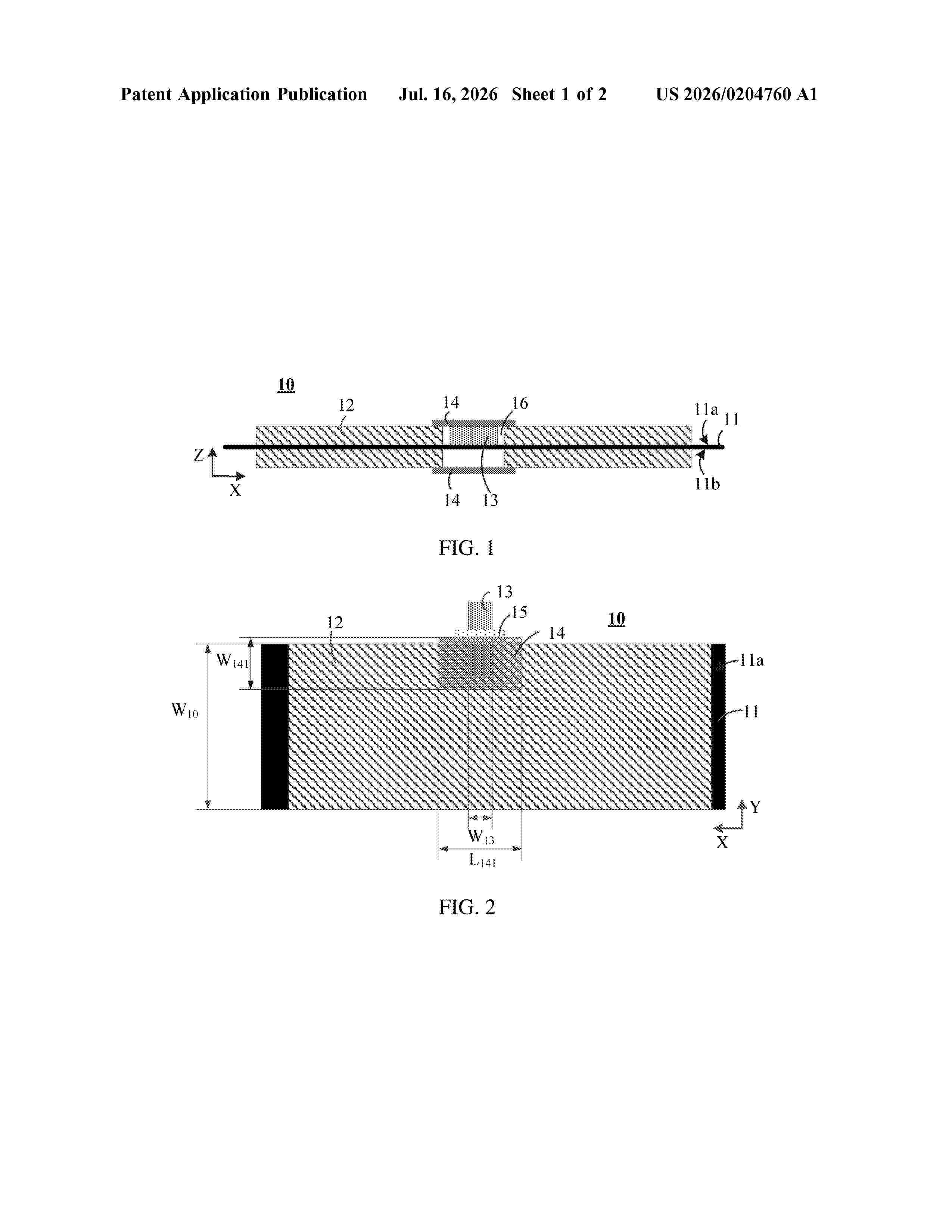
Resumen de: US20260204760A1
A positive electrode sheet in the secondary battery includes a positive electrode current collector, a positive electrode active material layer, and a positive electrode tab, where the positive electrode active material layer is disposed on at least one surface of the positive electrode current collector. The positive electrode active material layer is provided with a first groove exposing the positive electrode current collector. The positive electrode tab is disposed in the first groove and connected to the positive electrode current collector. An insulating tape is provided on each of a surface of the positive electrode tab and a region, corresponding to the first groove, of a surface of the positive electrode sheet away from the positive electrode tab. A melting point of the insulating tape is 250° C. to 450° C. An electrolyte includes carbonate and carboxylate.
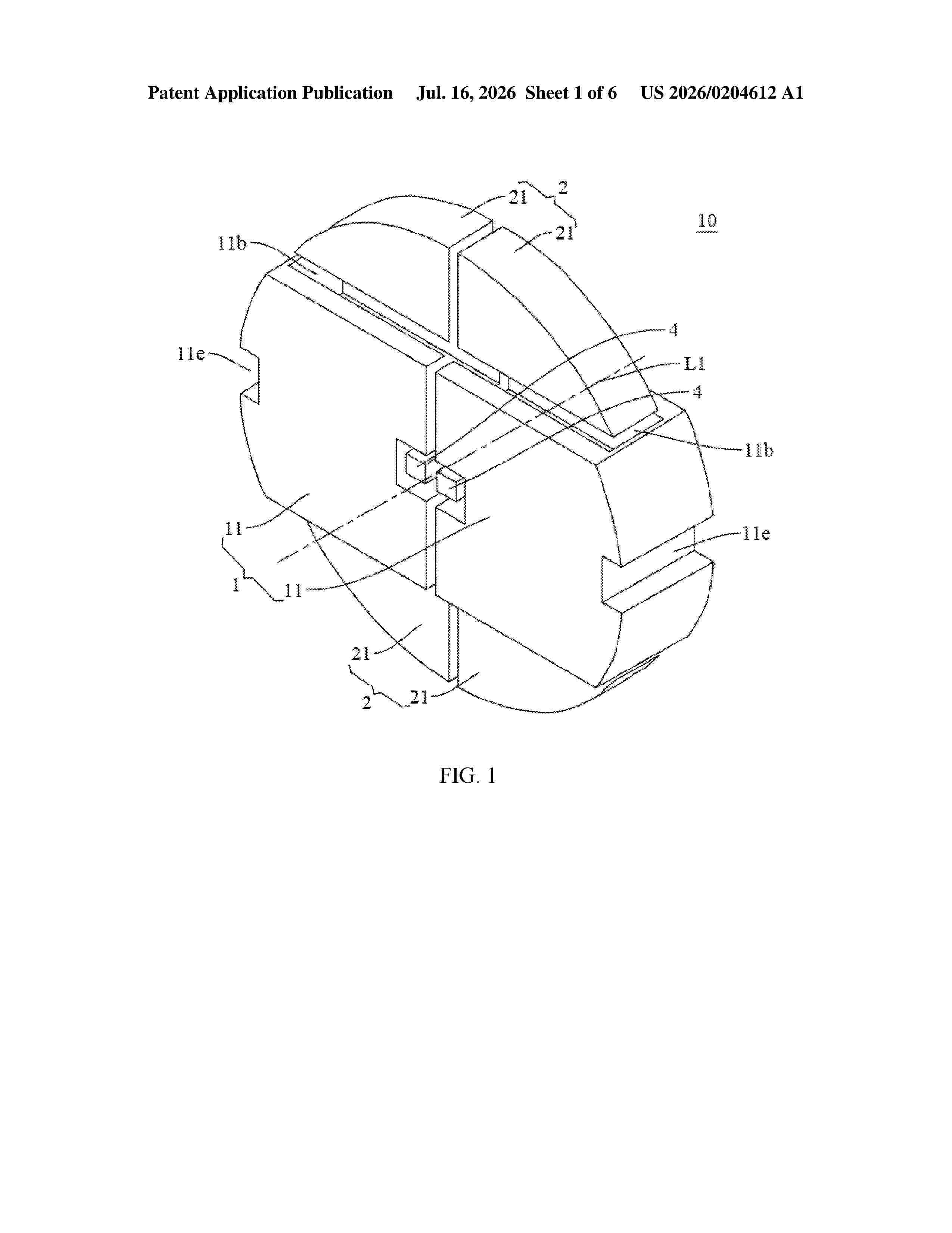
Resumen de: US20260204612A1
A winding member assembly includes a first winding member and a second winding member. The first winding member includes two first sub-winding members movable relative to each other along a first direction. The first winding member is provided with second winding members on two sides along a second direction respectively. In a first state, an outer peripheral wall of the second winding member and an outer peripheral wall of the first sub-winding member are in a same preset cylindrical surface. In a second state, the second winding member is located inside the preset cylindrical surface and at least part of the second winding member extends into an accommodating cavity through a corresponding fitting opening, so that a width of the winding member assembly in the second state in the second direction is smaller than a width of the winding member assembly in the first state in the second direction.
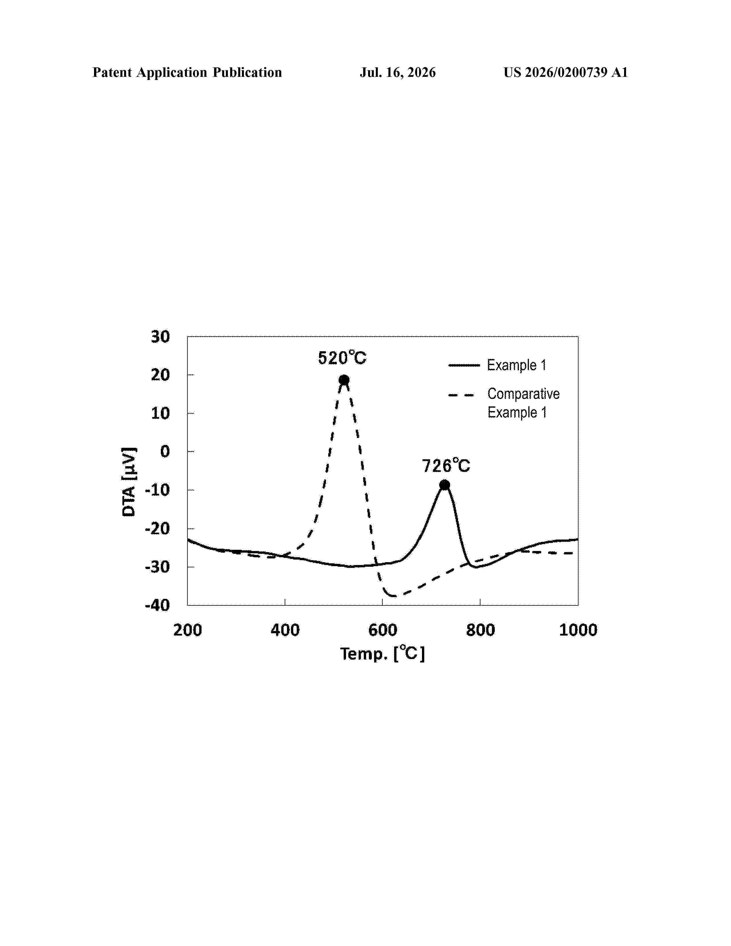
Resumen de: US20260200739A1
The disclosure provides: carbon nanotubes capable of forming an electrode film having good conductivity while further enhancing safety, and a method for purifying the carbon nanotubes; and a carbon nanotube dispersion, a binder composition, an electrode composition, and a secondary cell containing the carbon nanotubes.
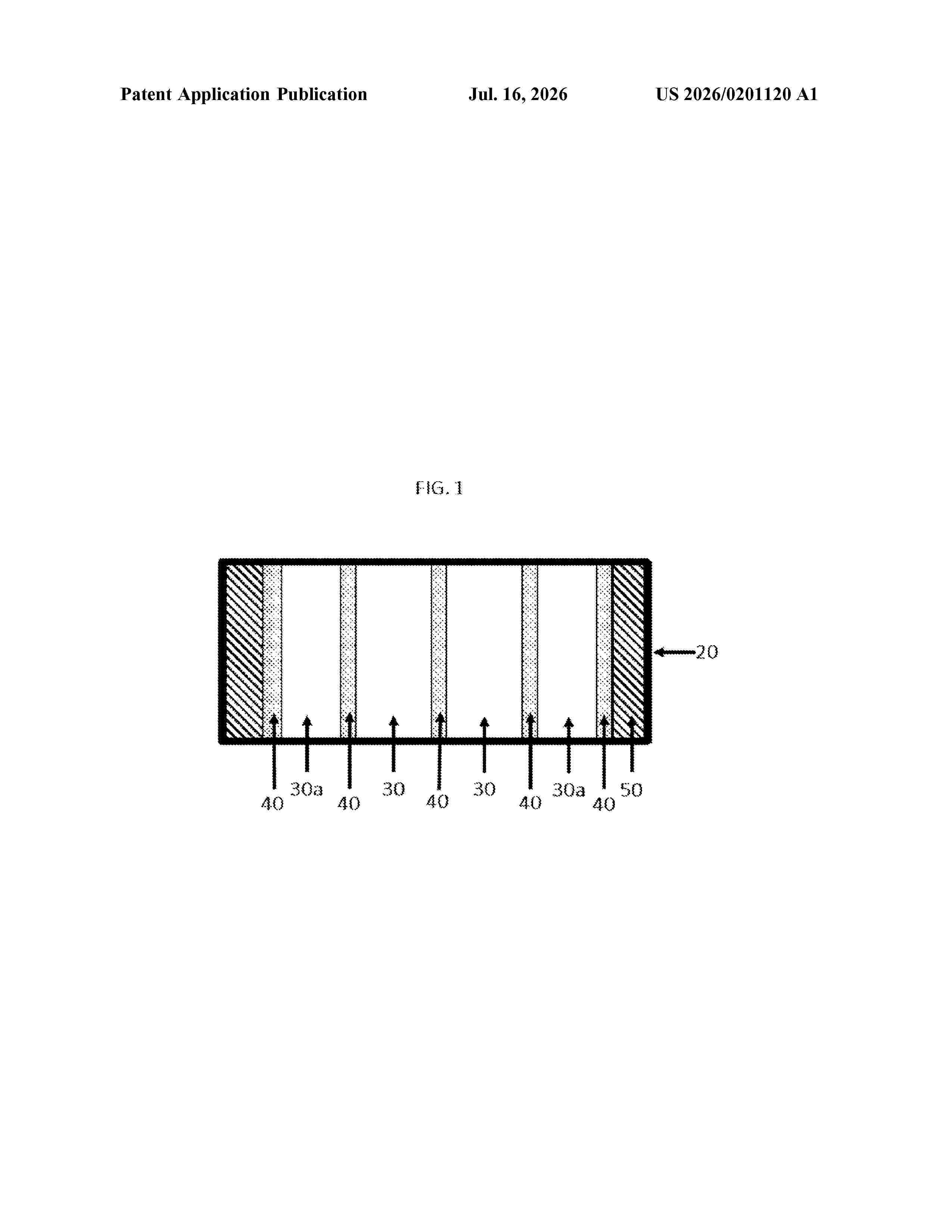
Resumen de: US20260201120A1
0000 The present invention relates to composition comprising a first polyorganosiloxane functionalized with a relatively high concentration of D
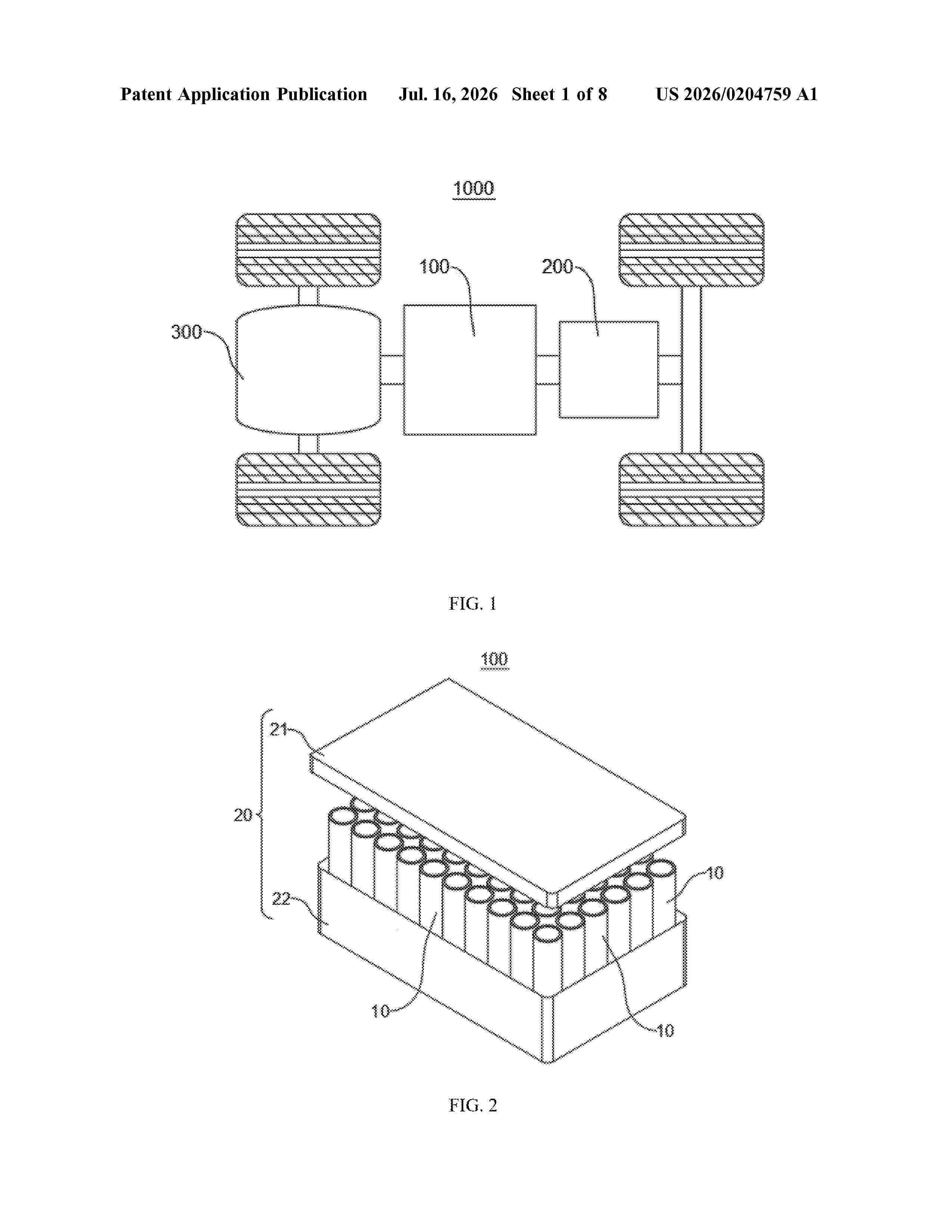
Resumen de: US20260204759A1
0000 A battery cell includes a housing, an electrode terminal, an electrode assembly, and a first insulating member. The housing has a first wall and a second wall, where the second wall surrounds an edge of the first wall. The electrode terminal is mounted on the first wall in an insulating manner. The electrode assembly is accommodated in the housing, and the electrode assembly includes a main body portion, a first tab, and a second tab, where the first tab and the second tab have opposite polarities, along a thickness direction of the first wall, the main body portion has a first end surface close to the first wall, the first tab and the second tab are both provided on the first end surface, the first tab is electrically connected to the electrode terminal, and the second tab is electrically connected to the housing.
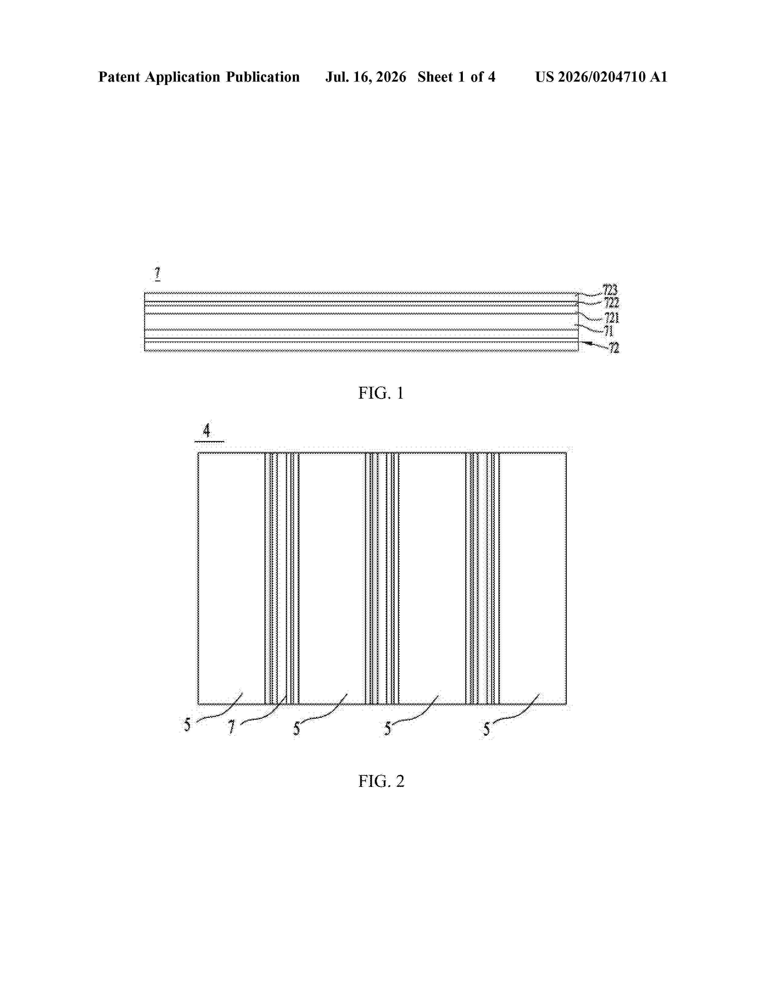
Resumen de: US20260204710A1
0000 The present application relates to a bonding assembly, a battery, and an electric apparatus. The bonding assembly includes a main body member and a connecting member, where the main body member includes first rubber; and the connecting member is connected to at least one side of the main body member in its thickness direction, and the connecting member includes a substrate, a connecting layer, and a bonding layer. The connecting layer is provided on a side of the substrate facing the main body member and bonds the substrate to the main body member. The connecting layer includes second rubber. Materials of the second rubber and the first rubber are the same or different. The bonding layer is bonded to a side of the substrate facing away from the connecting layer. When the bonding assembly is used in the battery, the structural stability of the battery can be improved.
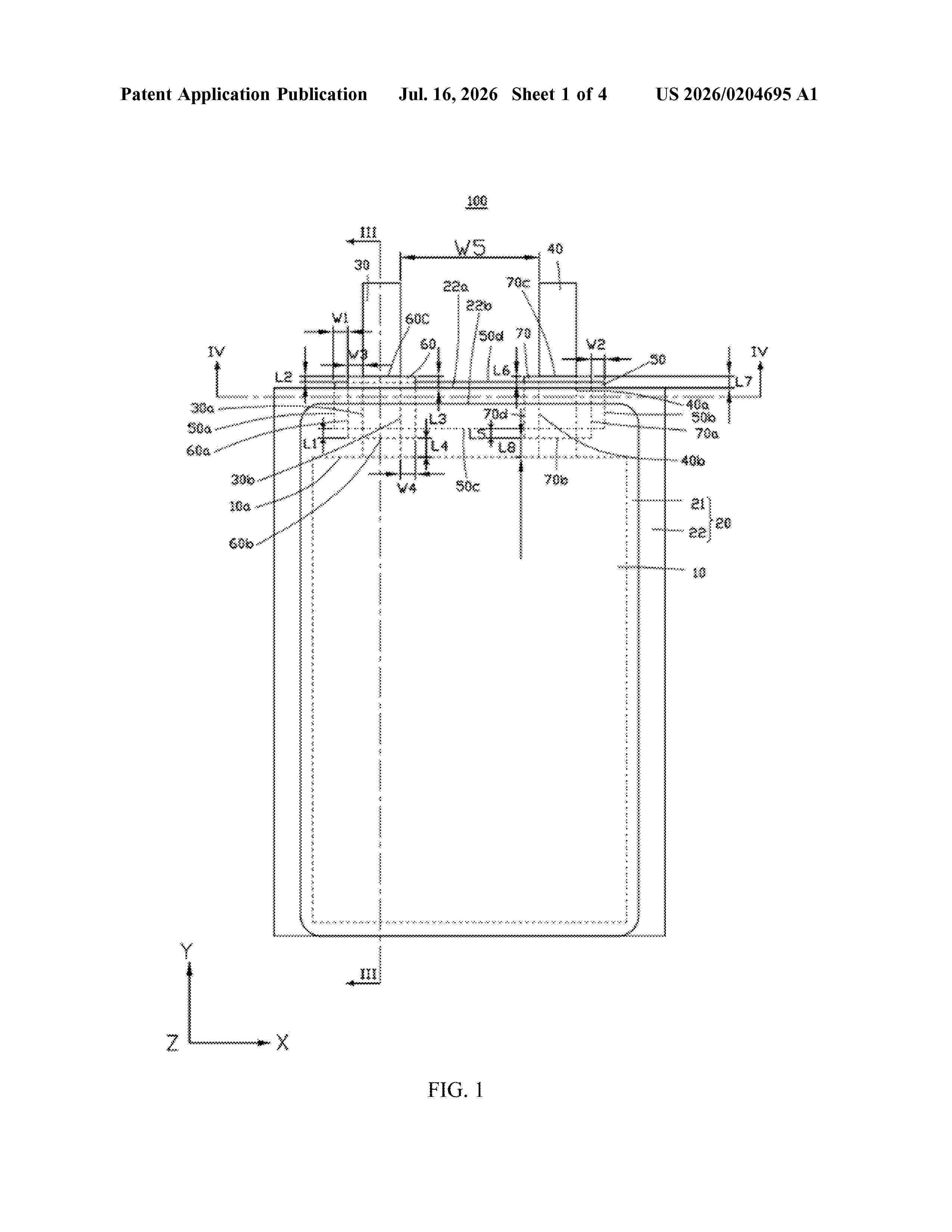
Resumen de: US20260204695A1
0000 A secondary battery includes a first packaging portion and a second packaging portion, the first packaging portion including a first region and a second region connected to each other, and the second packaging portion including a third region and a fourth region connected to each other. The second region and the fourth region form a main body portion accommodating an electrode assembly, and the first region and the third region are connected to form a sealing portion sealing the main body portion, the sealing portion including a first sealing portion and a second sealing portion. A distance between a first metal plate and a second metal plate is less than 1.5 mm. Along a first direction, a sealing film is disposed between the first insulating layer and the second insulating layer. The sealing film includes a first surface facing the first region and a second surface facing the third region.
Nº publicación: US20260204927A1 16/07/2026
Solicitante:
NYOBOLT LTD [GB]
NYOBOLT LIMITED
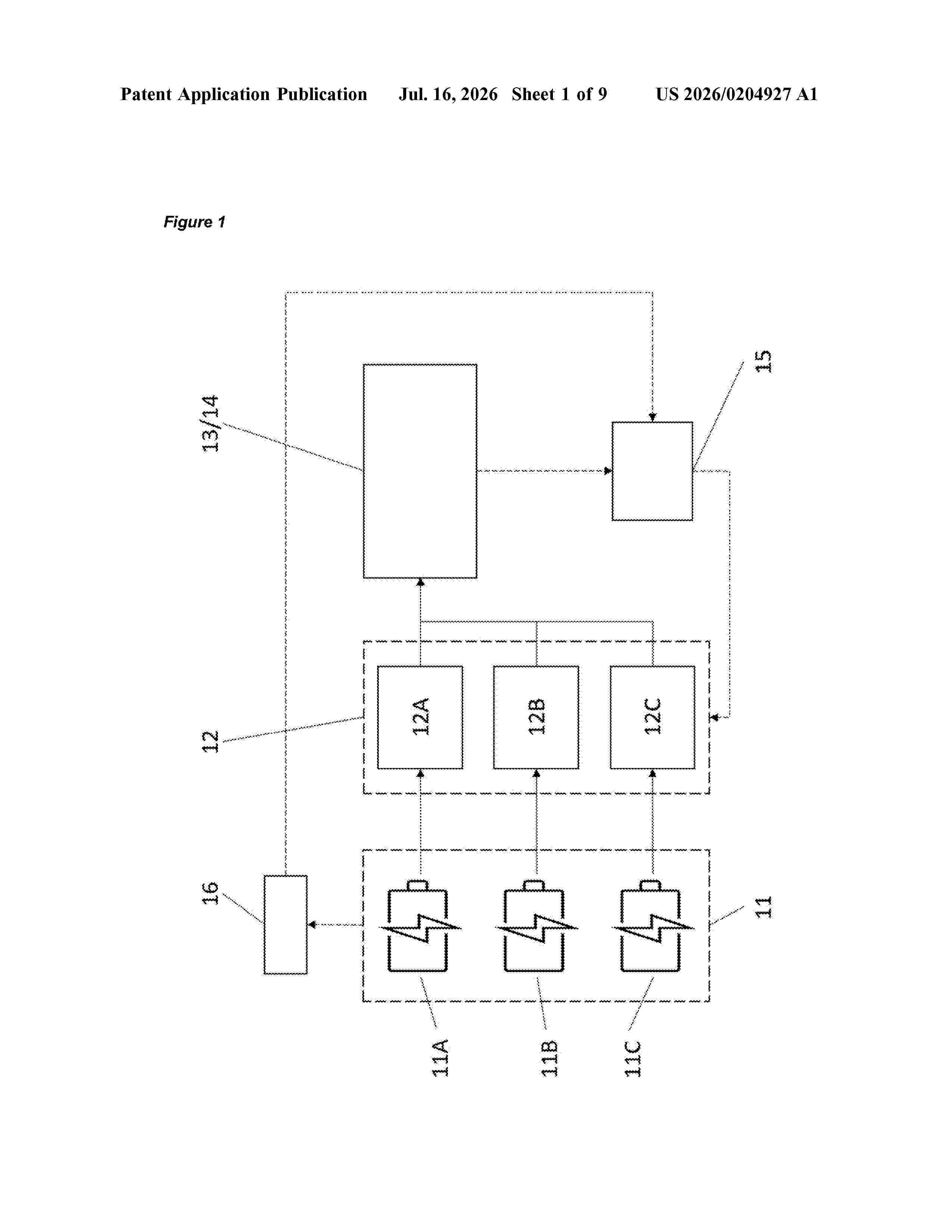
Resumen de: US20260204927A1
0000 The invention relates to a method and system for charging multiple batteries to a load or charging multiple batteries from a source, and a use of the system. The system comprises two or more batteries wherein two of the batteries have one or more different aspects; a power connector for electrically connecting the batteries to a load or a source; a power converter in electrical communication with the batteries and the power connector, wherein the power converter is for independently controlling the rate of discharge or charge of each of the batteries; and a controller in communication with the batteries and the power converter, wherein the controller is for adjusting the rate of discharge or charge of the batteries in response to data receivable from the batteries, for providing a constant power from the batteries to the load, or from the source to the batteries.
 BOPI
BOPI
 Sede Electrónica