Si deseas distinguir tus productos, servicios o ambos de los de otra empresa, es posible que necesites una marca o nombre comercial. Descubre qué son, en qué consiste su procedimiento de registro y qué implica.

Información sobre los plazos de presentación de solicitudes de transformación de marcas de la Unión Europea en marca nacional española. Más información


Si tienes un nuevo dispositivo, producto o procedimiento que resuelva un problema técnico o tenga una ventaja práctica, existen distintas formas de protegerlo en España y en otros países. Descubre cómo hacerlo.

¿Tu innovación reside en la estética, la ornamentación o la apariencia de tu producto? Protégela mediante un diseño industrial. Descubre qué derechos confiere el registro y cómo realizar la tramitación.

Las indicaciones geográficas protegen el nombre de un producto originario de una zona geográfica, a la cual le debe una determinada calidad, reputación u otra característica. Descubre qué son, en qué consiste su procedimiento de registro y qué beneficios conceden.

Las patentes publicadas en todo el mundo son una valiosa fuente de información científica, técnica y comercial.

Si eres emprendedor/a o una empresa y quieres potenciar y mejorar la rentabilidad de tu negocio protegiendo de forma adecuada los activos intangibles de tu organización, en este espacio encontrarás lo necesario.


 73
resultados
73
resultados
 Última actualización
01/05/2026 [07:52:00]
Última actualización
01/05/2026 [07:52:00]


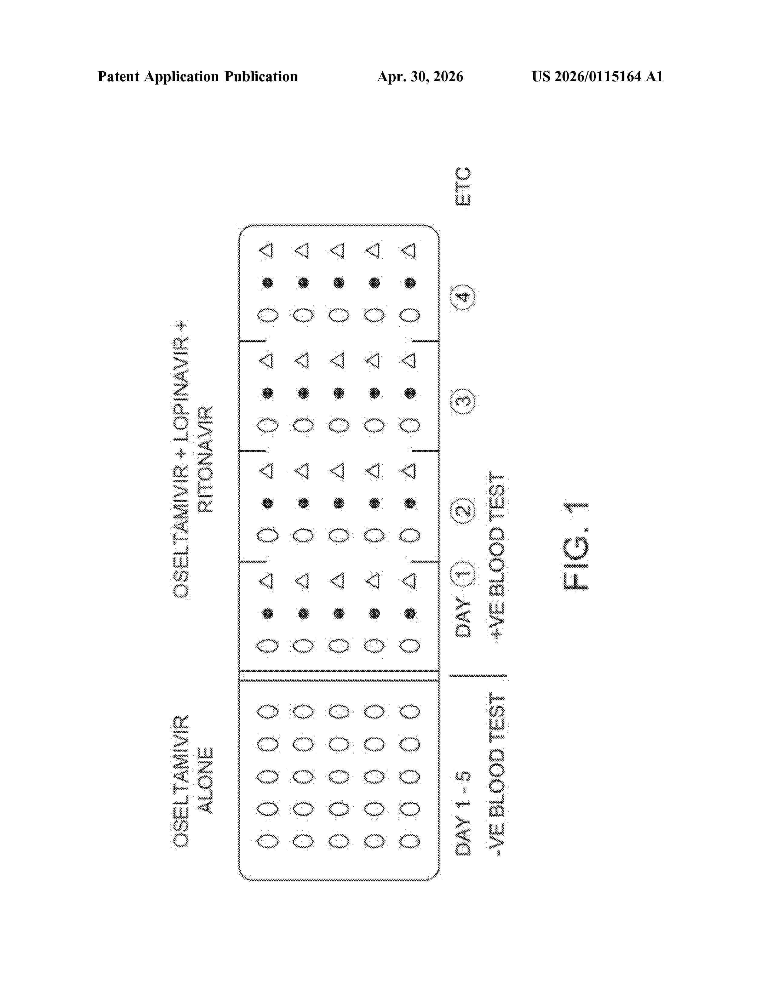
Resumen de: US20260115164A1
In alternative embodiments, provided are pharmaceutical compositions comprising combinations of drugs, including products of manufacture and kits, and methods for using them, for treating, preventing, ameliorating, slowing the progress of, decreasing the severity of or preventing a coronavirus infection, or a COVID-19 or a 2019-nCoV (or so-called Wuhan coronavirus) infection, or an infection caused by a virus in the subfamily Orthocoronavirinae, or a virus in the family Coronaviridae, or a virus in the order Nidovirales. In alternative embodiments, combinations, or cocktails, of a drug or drugs as provided herein are administered either enterally, parenterally and/or by inhalation. In alternative embodiments, combinations, or cocktails, of drugs as provided herein are used to block intracellular metabolic pathways and prevent progression of the infection to clinical illness and death. In alternative embodiments, novel aerosol, spray or mist or powder formulations for inhalation are provided.

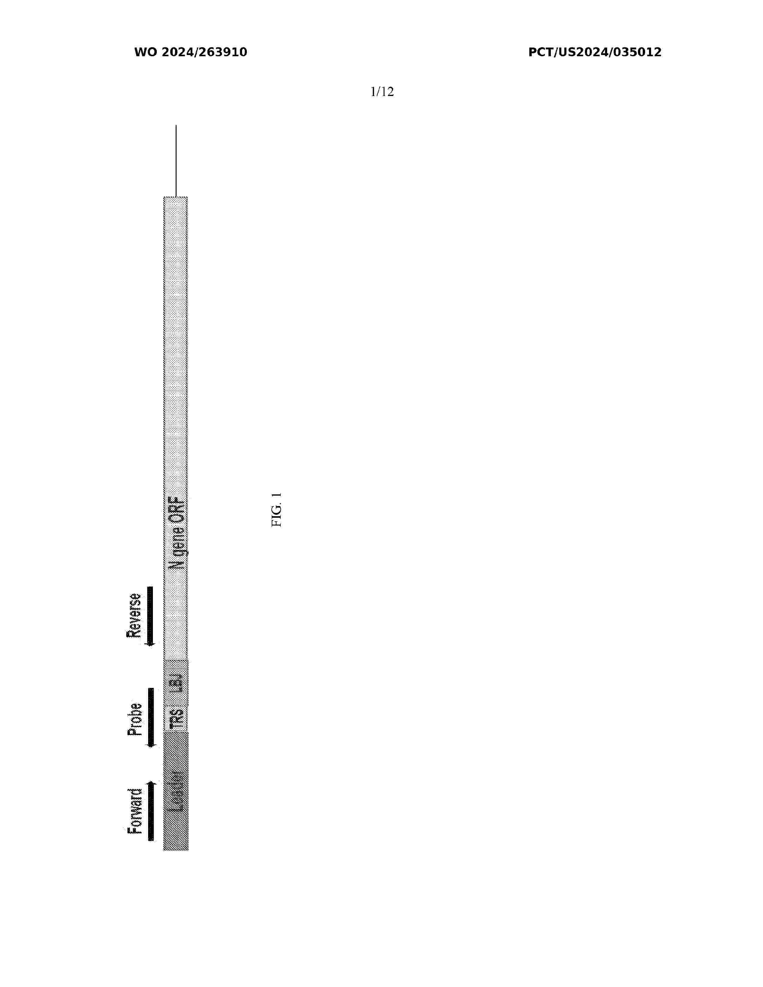
Resumen de: WO2024263910A1
Provided is method of detecting SARS-CoV-2 in a sample, including amplifying polynucleotides in the sample to form subgenomic amplicons using a forward subgenomic primer and a reverse subgenomic primer, wherein the forward subgenomic primer hybridizes to a forward subgenomic primer target of a subgenomic SARS-CoV-2 N protein transcript or its complement and the reverse subgenomic primer hybridizes to a reverse subgenomic primer target of the subgenomic SARS-CoV-2 transcript or its complement, and detecting an amount of hybridization of a subgenomic SARS-CoV-2 transcript probe to the subgenomic amplicons, wherein the subgenomic SARS-CoV-2 transcript probe hybridizes to a probe target of the subgenomic amplicons, wherein the probe target of the subgenomic amplicons includes at least a portion of a leader sequence, a transcriptional regulatory sequence, and at least a portion of a junction region between the transcriptional regulatory sequence and a coding sequence of the subgenomic SARS-CoV-2 transcript and the probe target is between the forward subgenomic primer target and the reverse subgenomic primer target
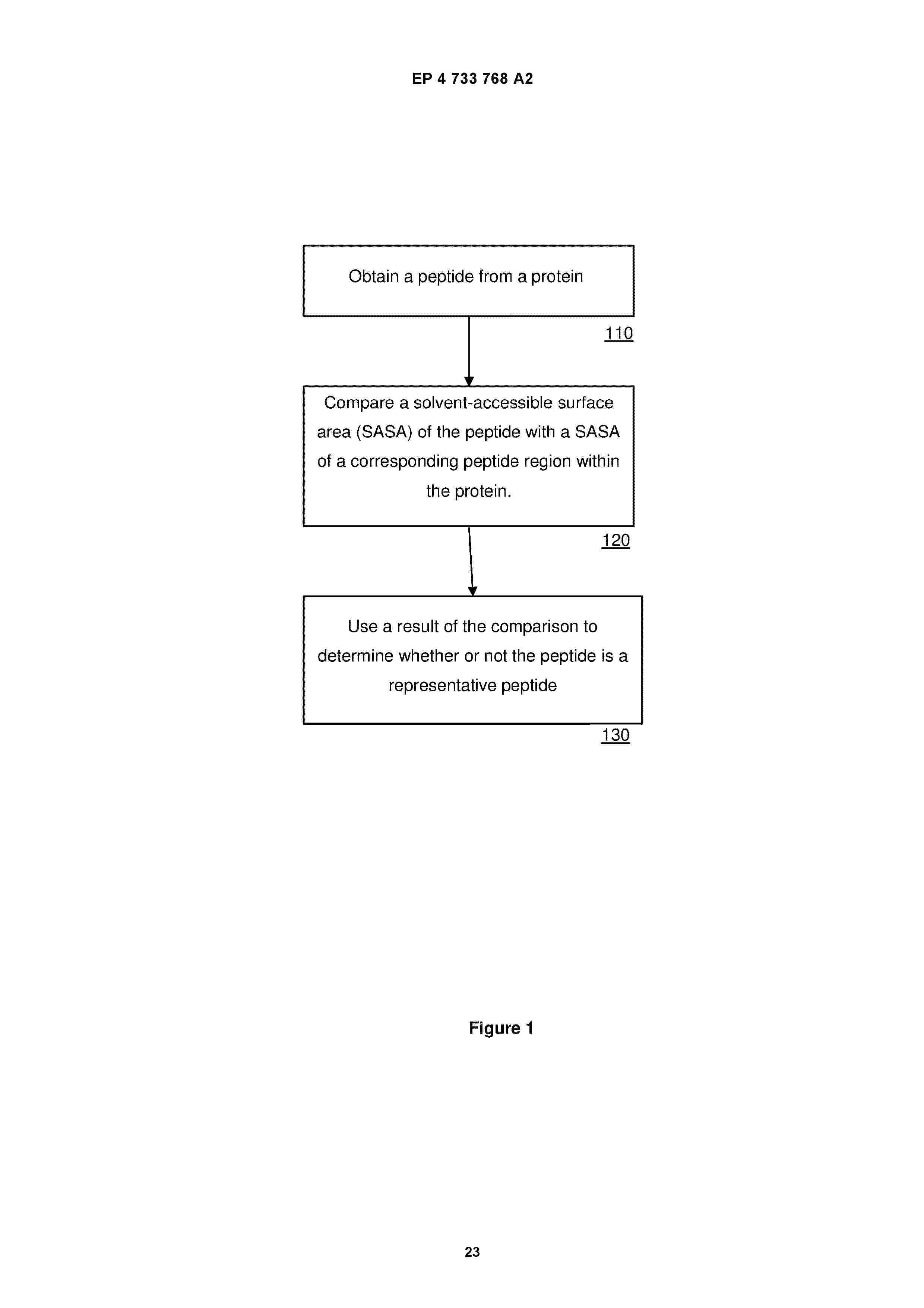
Resumen de: EP4733768A2
0001 A method of identifying stable peptides from a protein, said method comprising: obtaining a peptide from a protein; comparing a solvent-accessible surface area (SASA) of the peptide with a SASA of a corresponding peptide region within the protein; using a result of the comparison to determine whether or not the peptide is structurally stable relative to the corresponding peptide region within the protein. Also disclosed is use of the method to identify stable immunogenic epitopes of SARS-CoV-2, and methods of detecting an antibody response.
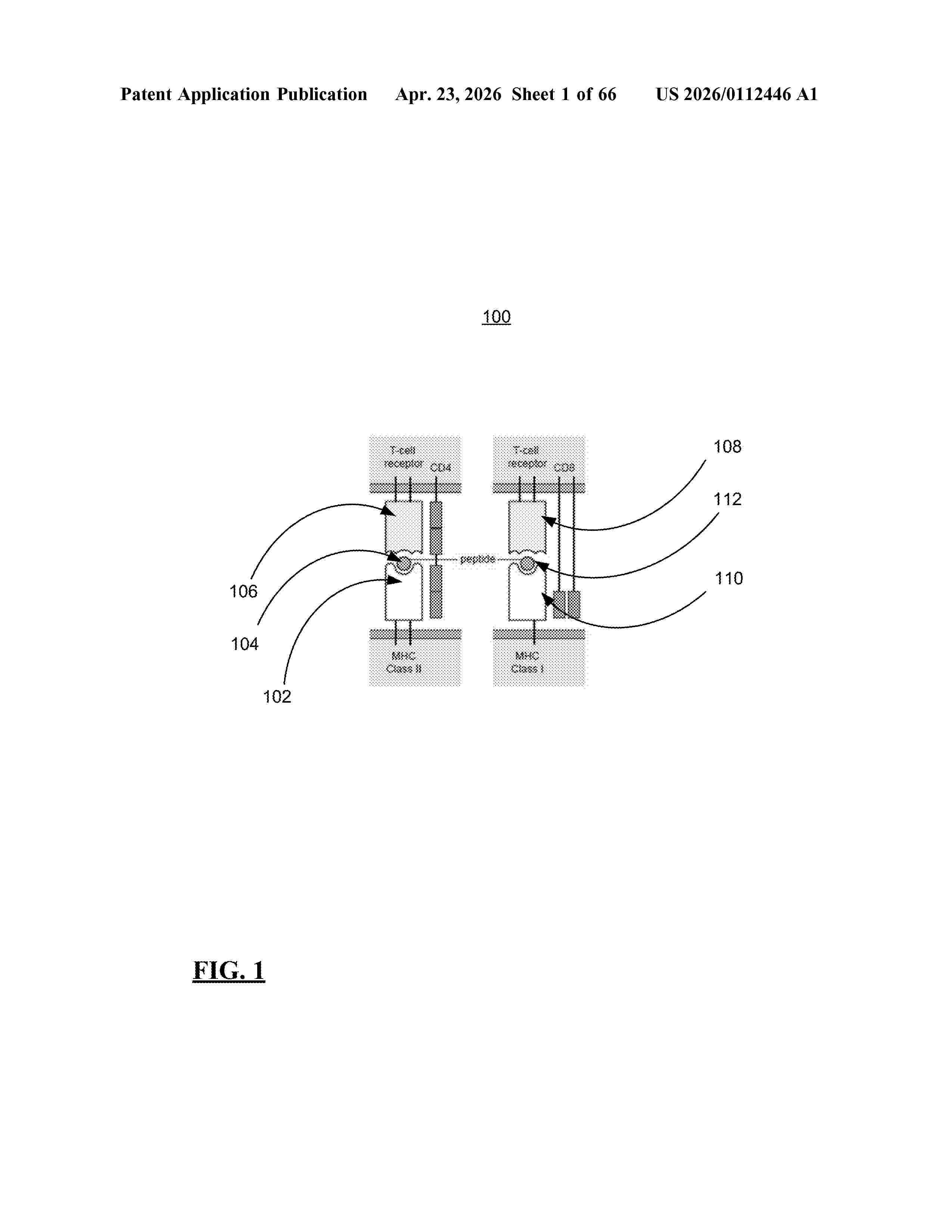
Resumen de: US20260112446A1
0000 Techniques are provided for determining pan-HLA binding of viral proteins. A trained classifier model is operable to determine, independently per HLA, at least one of (a) an average binding prediction of overlapping peptides at each position of a viral protein, (b) a maximum value of a binding prediction of overlapping peptides at each position of the viral protein, (c) standard deviation of a binding prediction of overlapping peptides at each position of the viral protein, and (d) a combination of one or more of (a)-(c). A classification engine uses the classifier model to determine average binding predictions of overlapping peptides at each position of the viral protein independently for test HLA-I and HLA-II functional groupings, where a peptide is classified as a binder when an average binding prediction corresponding to the peptide satisfies a binding value threshold.
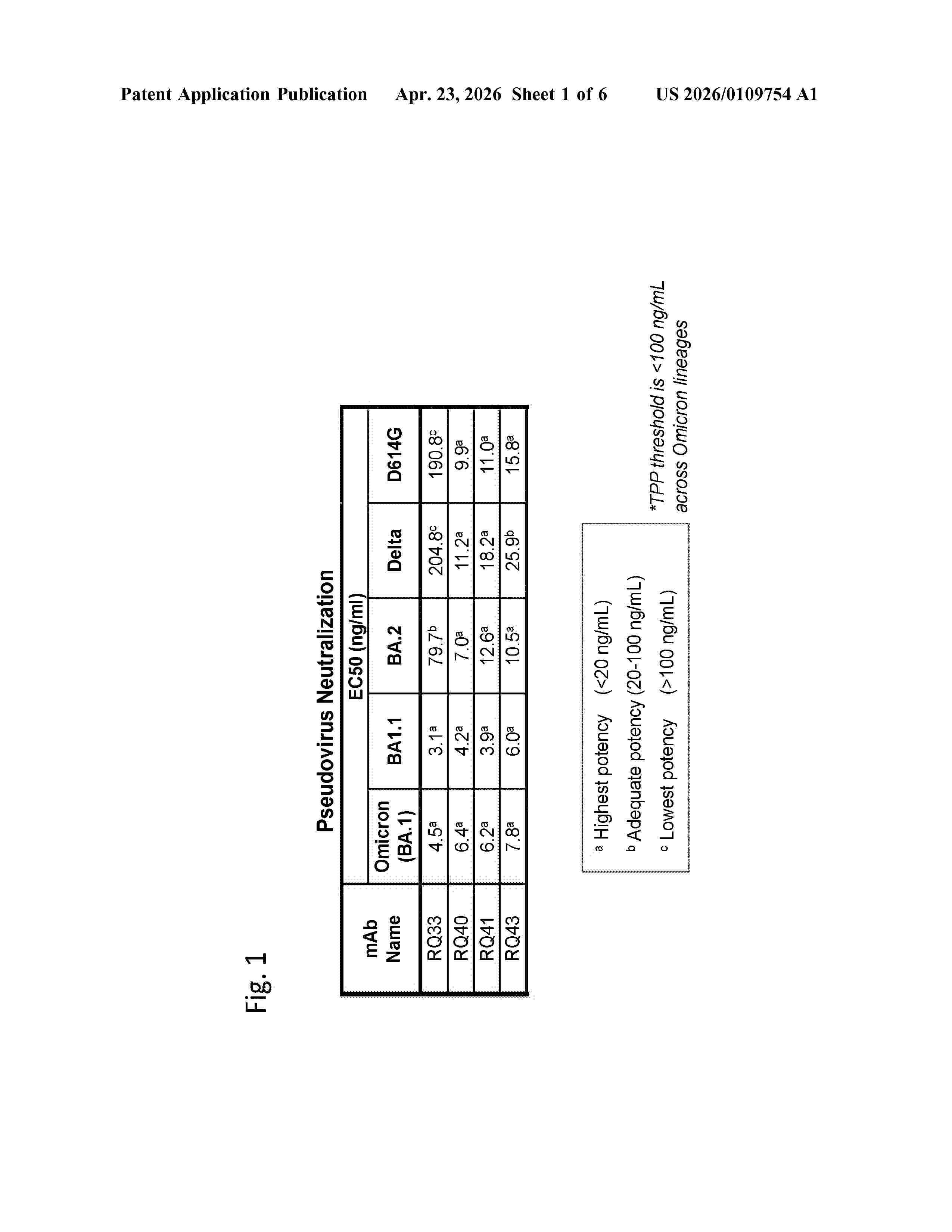
Resumen de: US20260109754A1
0000 The present disclosure provides antibodies and antigen-binding fragments thereof that specifically bind to the spike protein of SARS-CoV-2 and methods of making and using the same. The antibodies can be used, for example, in prophylaxis, post-exposure prophylaxis, or treatment of SARS-CoV-2 infection. The antibodies can also be used to detect SARS-CoV-2, e.g., an infection in subject.
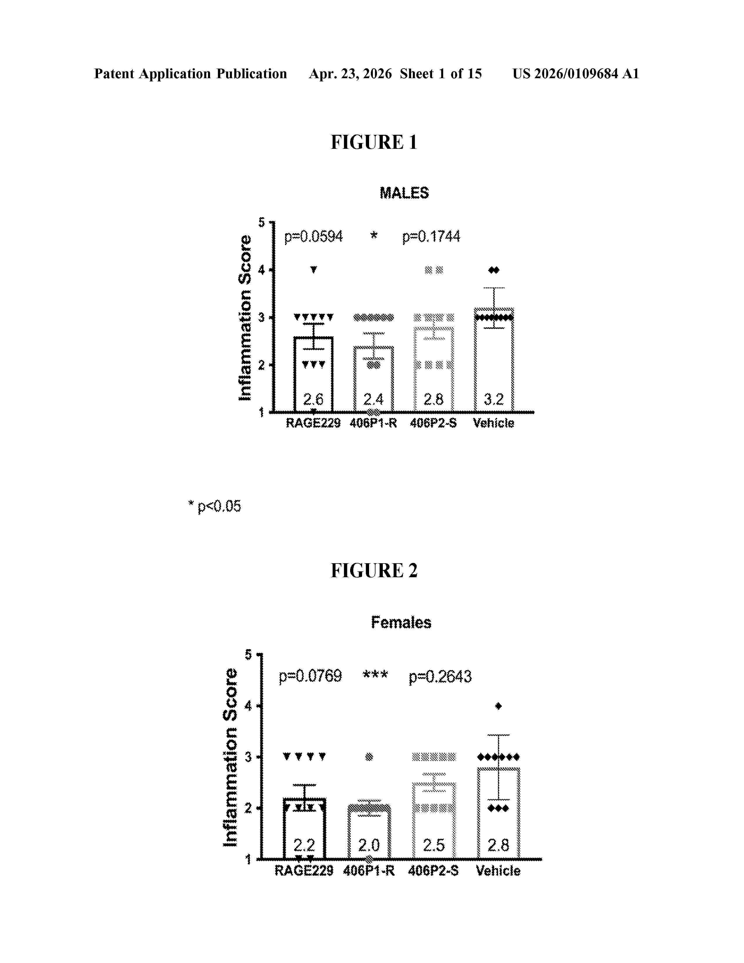
Resumen de: US20260109684A1
0000 Quinoline compounds are disclosed that have a formula represented by the following; and wherein Cy, R1, R4a, R4b, and n are as described herein. The compounds may be prepared as compositions, e g., pharmaceutical compositions, or as dosage forms, e.g., pharmaceutical dosage forms, and may be used for the prevention and treatment of a variety of conditions in mammals including humans, including by way of non-limiting example, diabetes complications, inflammation, and neurodegeneration, obesity, cancer, ischemia/reperfusion injury, cardiovascular disease, COVID-19 complications, and other diseases related to RAGE activity.
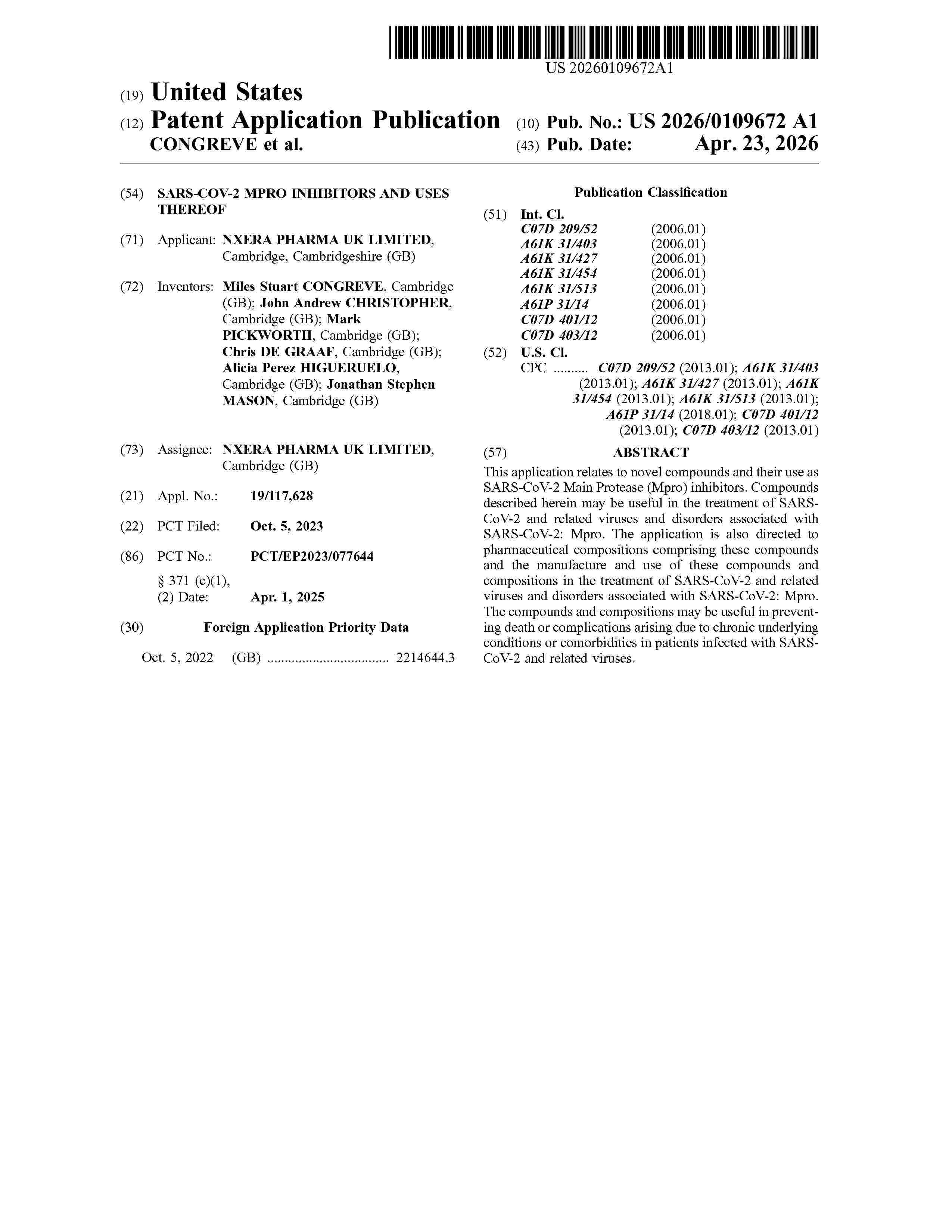
Resumen de: US20260109672A1
This application relates to novel compounds and their use as SARS-CoV-2 Main Protease (Mpro) inhibitors. Compounds described herein may be useful in the treatment of SARS-CoV-2 and related viruses and disorders associated with SARS-CoV-2: Mpro. The application is also directed to pharmaceutical compositions comprising these compounds and the manufacture and use of these compounds and compositions in the treatment of SARS-CoV-2 and related viruses and disorders associated with SARS-CoV-2: Mpro. The compounds and compositions may be useful in preventing death or complications arising due to chronic underlying conditions or comorbidities in patients infected with SARS-CoV-2 and related viruses.
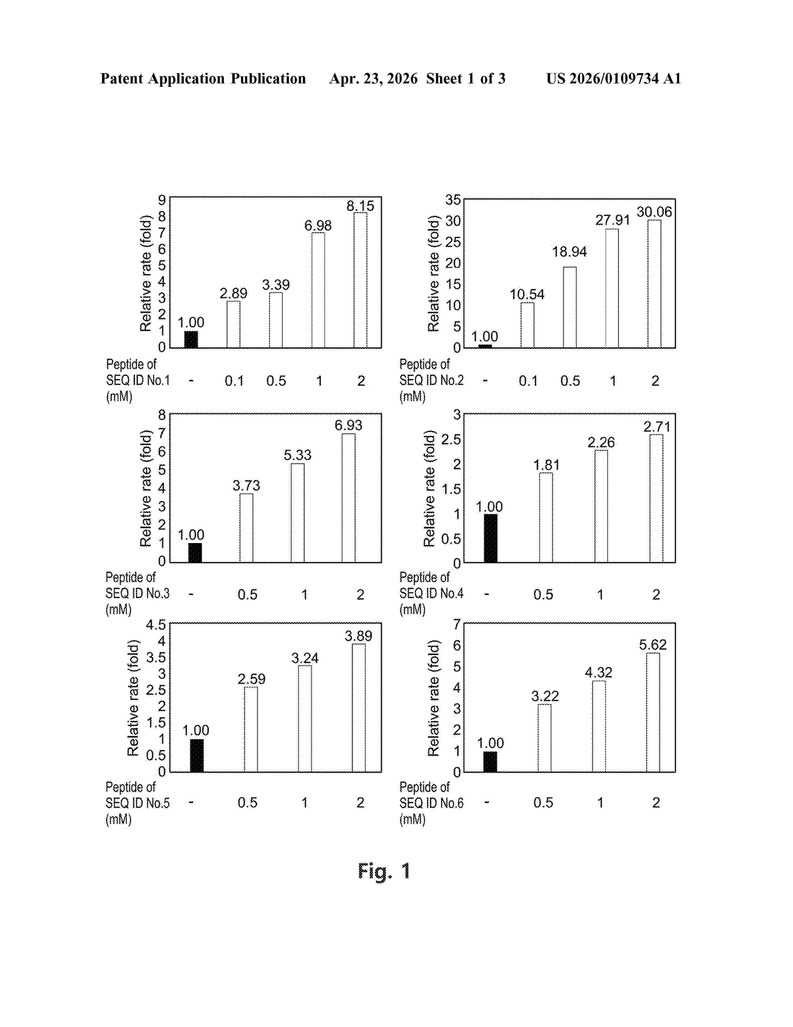
Resumen de: US20260109734A1
0000 The present invention relates to a peptide that specifically recognizes a protein of severe acute respiratory syndrome coronavirus 2 (SARS-CoV-2) or a portion thereof, a composition for preventing or treating SARS-CoV-2 infection, comprising the peptide; and a composition for detecting SARS-CoV-2, comprising the peptide.
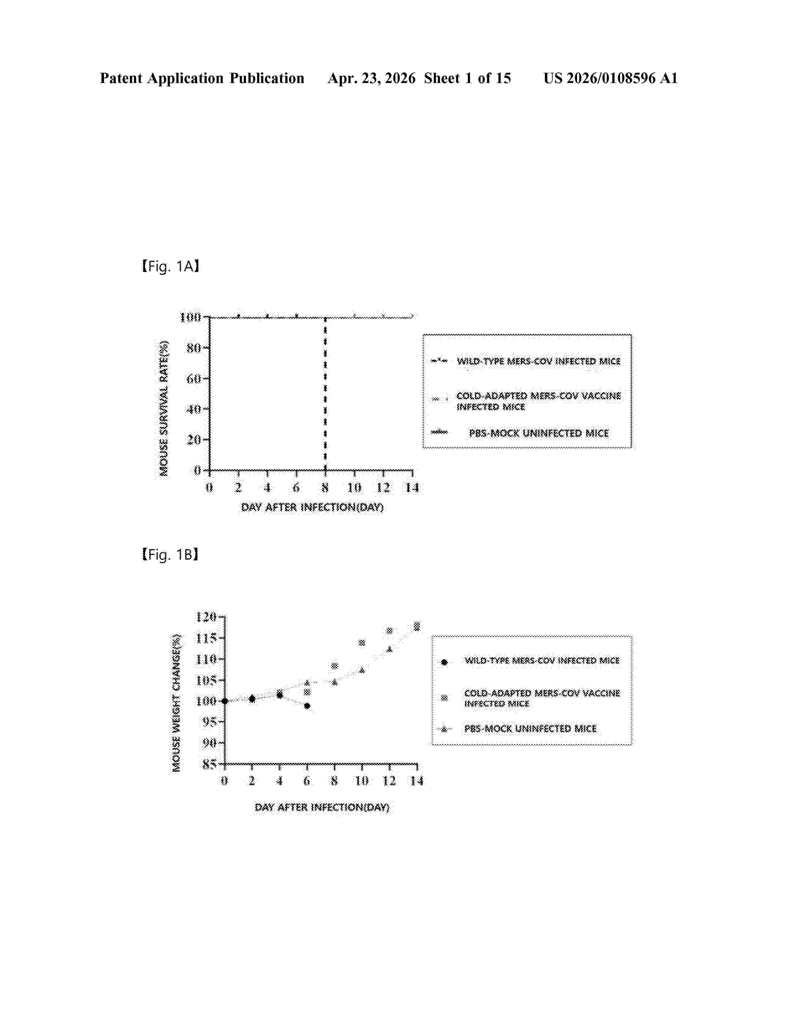
Resumen de: US20260108596A1
The present invention relates to a novel cold-adapted attenuated Middle East respiratory syndrome coronavirus (MERS-CoV) and uses thereof. According to the present invention, the novel attenuated Middle East respiratory syndrome coronavirus (MERS-CoV) capable of effectively preventing infection with MERS-CoV has been developed by cold-adapting the MERS-CoV gradually, and thus can be effectively used as vaccines and therapeutic agents capable of preventing and treating Middle East respiratory syndrome.
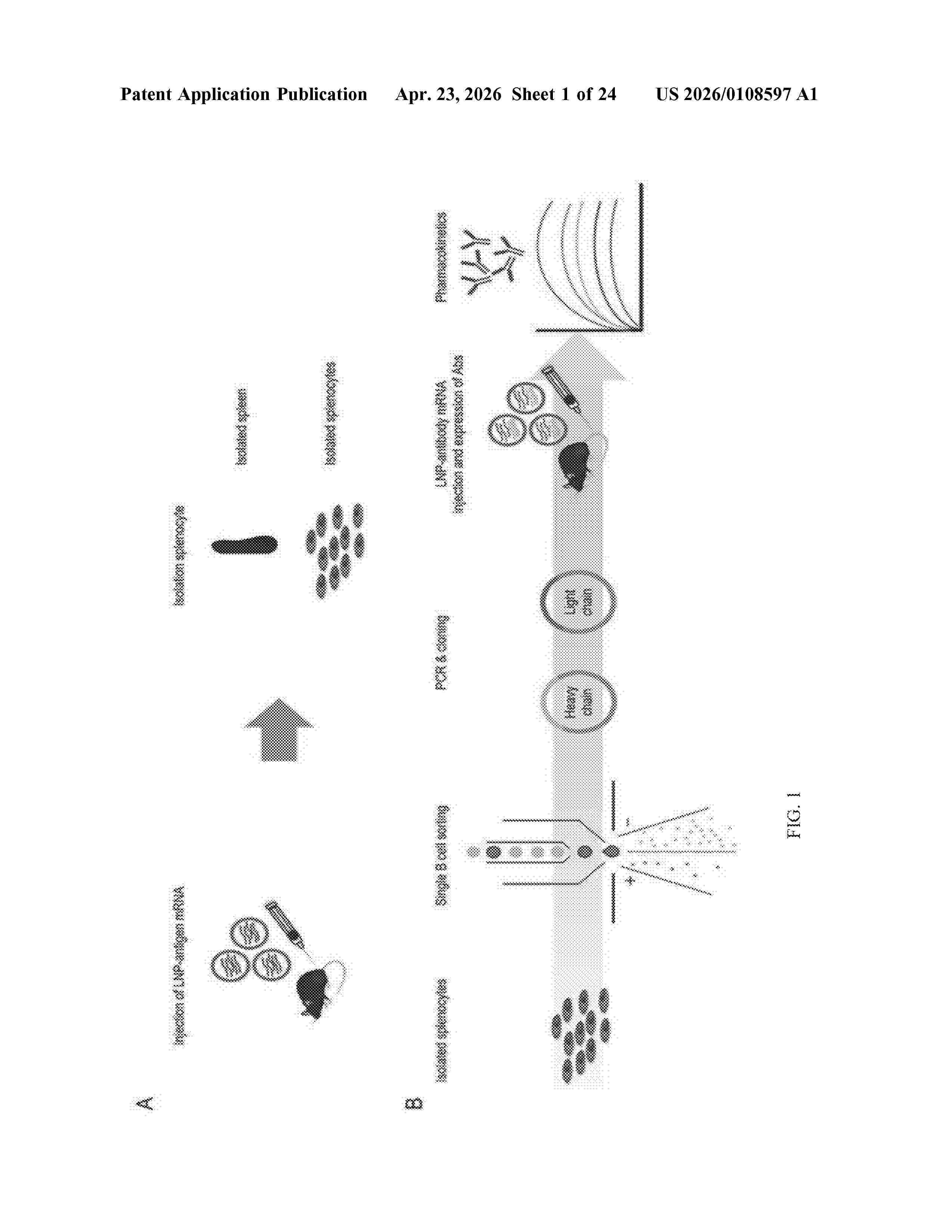
Resumen de: US20260108597A1
0000 The present invention relates to an antibody mRNA for treating SARS-coronavirus-2 delta infection and a composition including same, the composition exhibiting excellent therapeutic efficacy against SARS-coronavirus-2 delta infection.
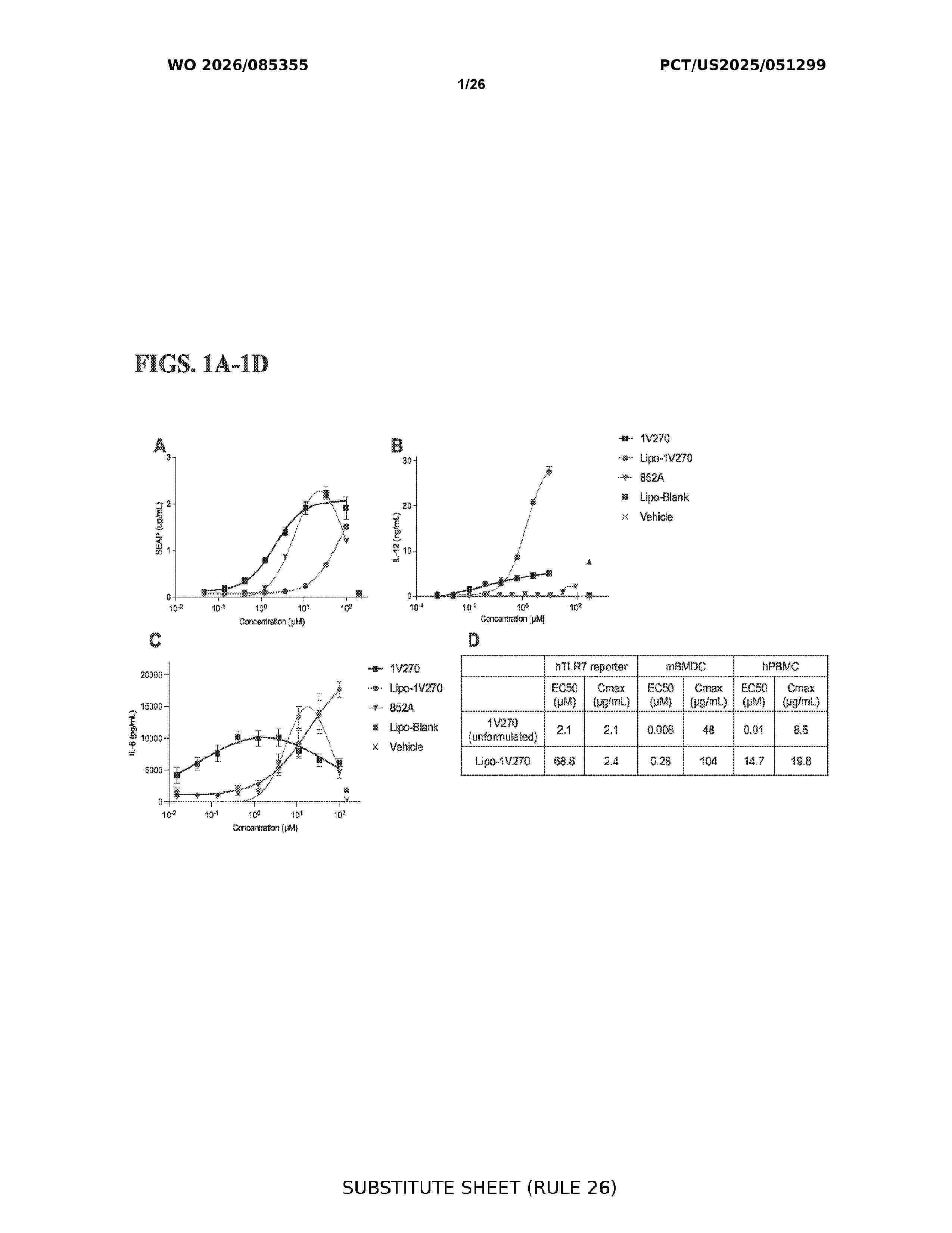
Resumen de: WO2026085355A1
The present disclosure pertains to the field of vaccine technologies, with a focus on improved vaccine adjuvants and their formulations for enhancing immune responses. The described approach addresses limitations of traditional adjuvants by introducing novel formulations of the TLR7 agonist 1 V270, either as a standalone agent or in combination with co-adjuvants such as 2G272 and 2E151. These formulations include self-assembling nanoparticles, lipid-incorporated nanoparticles, and aqueous or liposomal combinations, designed to enhance antigen-specific immune responses while maintaining favorable safety and stability profiles. Notable advantages include balanced Thl/Th2 immune responses, dose¬ sparing effects, cross-reactive immunity, and compatibility with modern vaccine platforms such as mRNA vaccines. Applications encompass systemic and mucosal immunization against a wide range of pathogens, including influenza, SARS-CoV-2, and other infectious diseases. The described approach demonstrates enhanced immunogenicity, durability, and efficacy, particularly in aged populations and those requiring heterologous prime-boost regimens.
Resumen de: WO2024257026A1
The present disclosure relates to a virus-like particle (VLP) comprising one or more antigens for use as a vaccine. The present disclosure further relates to uses of the vaccine for the treatment of a SARS-CoV-2 infection or coronavirus disease 2019 (COVID-19).
Resumen de: AU2024354738A1
Provided are coronavirus spike protein variants for use as antigens for vaccines for coronavirus infections. The present invention provides coronavirus spike protein variants comprising (a) a receptor binding domain (RBD) formed from the amino acid sequence set forth in SEQ ID NO: 1, (b) an RBD formed from an amino acid sequence in which one to several amino acids have been substituted, deleted, inserted, or added in the amino acid sequence set forth in SEQ ID NO: 1, and having neutralizing antibody-inducing activity against SARS-CoV-2 and SARS-CoV-1 equivalent to RBD formed from the amino acid sequence set forth in SEQ ID NO: 1, or (c) an RBD formed from an amino acid sequence having at least 90% sequence identity with the amino acid sequence set forth in SEQ ID NO: 1, and having neutralizing antibody-inducing activity against SARS-CoV-2 and SARS-CoV-1 equivalent to RBD formed from the amino acid sequence set forth in SEQ ID NO: 1.
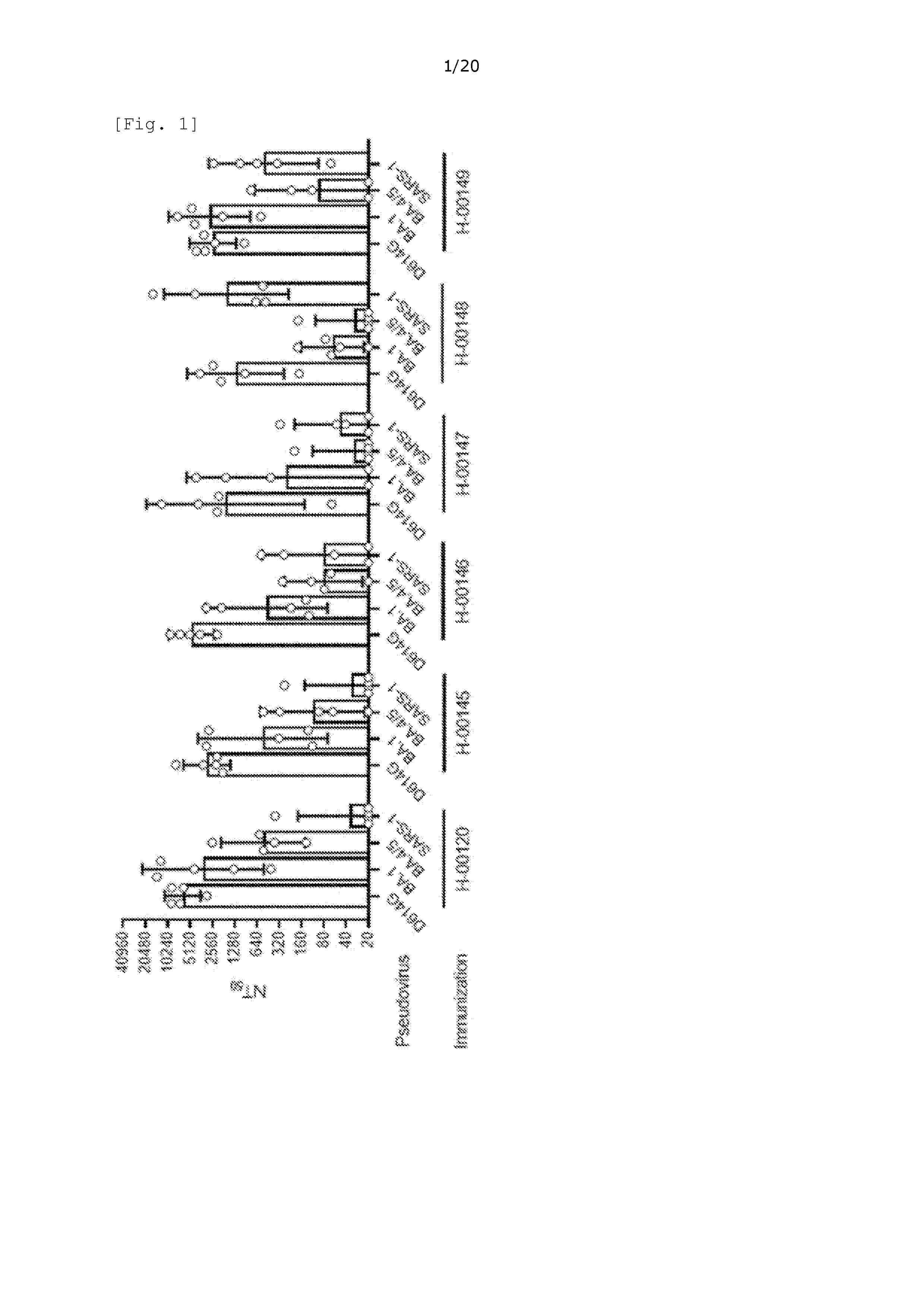
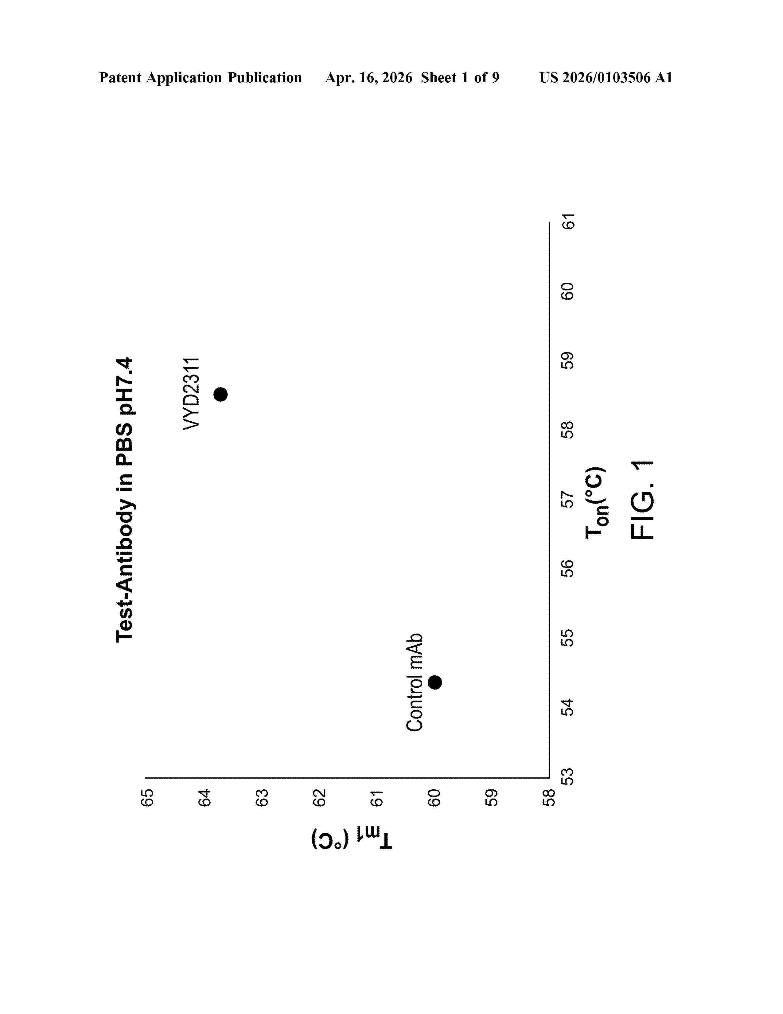
Resumen de: US20260103506A1
The present disclosure is directed to antibodies and antigen binding fragments thereof, having improved binding specificity for coronaviruses, such as SARS-CoV-2, including neutralizing antibodies. Other embodiments contemplate using anti-CoV-S antibodies, and binding fragments thereof, for the diagnosis, assessment, and treatment of diseases and disorders associated with coronaviruses or the S protein thereof and conditions where neutralization or inhibition of coronaviruses or the S protein thereof would be therapeutically beneficial.
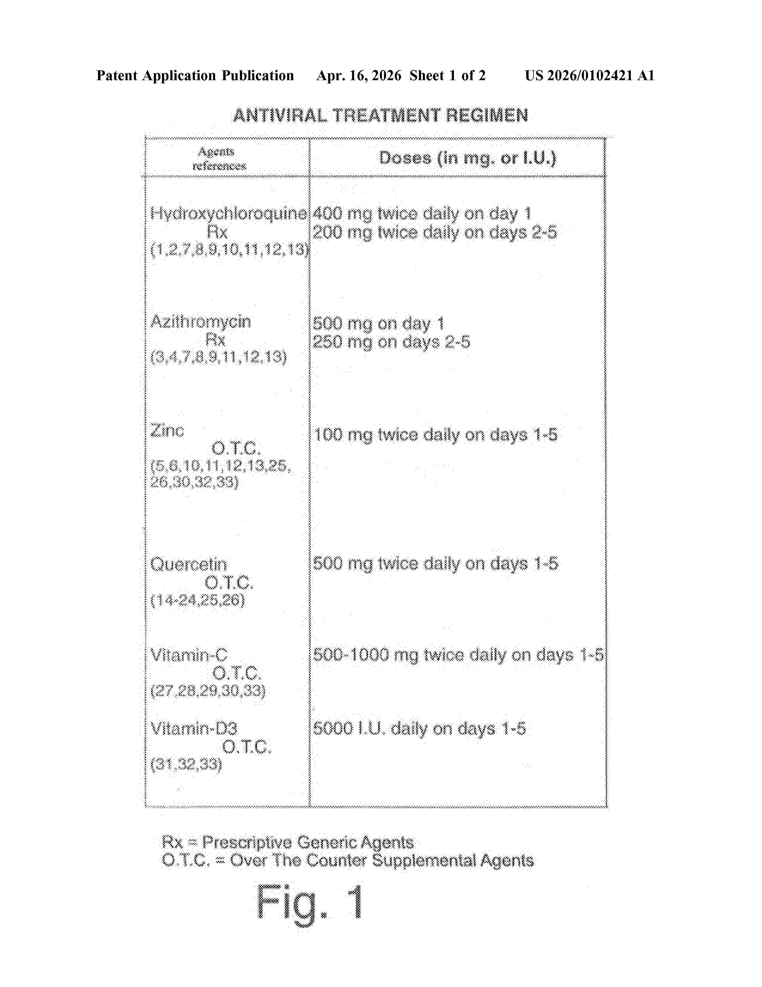
Resumen de: US20260102421A1
A method of treatment of Sars-COV-2 viral infections including Covid-19 and long Covid and of virus associated cognitive impairment and Lewy-Body Spectrum Dementia disorders in a six-agent treatment regimen of hydroxychloroquine, azithromycin, zinc, quercetin, vitamin C, and vitamin D3. The six-agent treatment is administered to the subject orally for, preferably, 5 days at which time the subject is cured of Covid-19. In an alternant embodiment, the method comprises administering to a subject an eight-agent treatment regimen of hydroxychloroquine, azithromycin, zinc, quercetin, vitamin C, vitamin D3, pregnenolone, and niacinamide. The addition of pregnenolone, and niacinamide to the six-agent treatment enhances the improvement of cognitive performance.
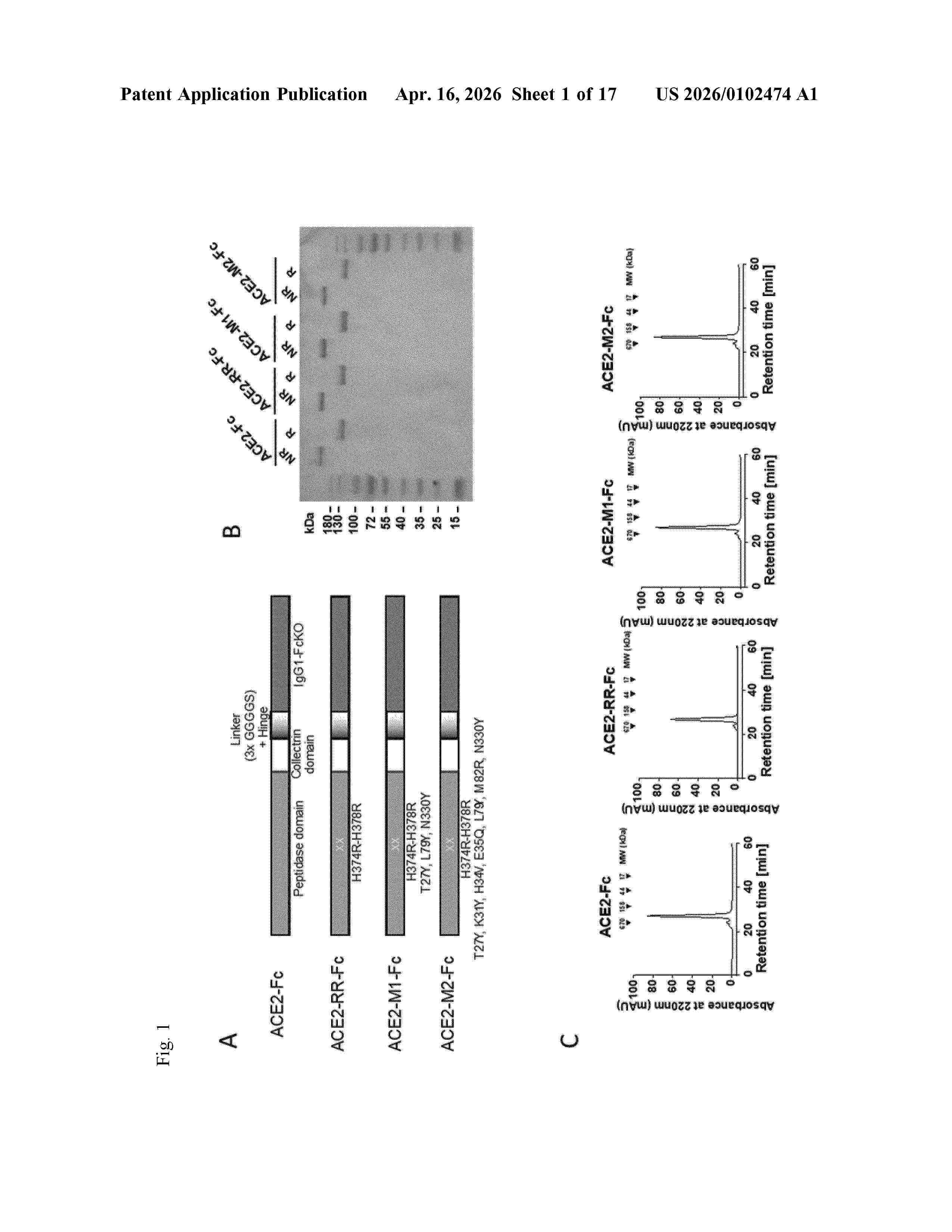
Resumen de: US20260102474A1
The present invention relates to therapeutic proteins and medical uses thereof. The present invention relates to modified ACE2 protein having increased binding affinity for the SARS-COV-2 spike protein compared to wildtype ACE2 protein, wherein said modified ACE2 protein is lacking enzymatic activity and is fused to (i) a modified Fc domain of human immunoglobulin, wherein the Fc domain has either enhanced immunostimulating activity (Fc+) or attenuated immunostimulating activity (Fc−) or (ii) a protein that specifically binds to T cells or further enhances immunostimulating activity. The invention also relates to a polynucleotide encoding the modified ACE2 protein of the present invention, a vector or expression construct comprising the polynucleotide, a host cell comprising the polynucleotide or the vector or expression construct, and a non-human transgenic organism comprising the polynucleotide or the vector or expression construct. Moreover, the present invention relates also to a method for the manufacture of a modified ACE protein according to the present invention and to a medicament comprising the modified ACE2 protein, the polynucleotide or the vector or expression construct of the invention. Furthermore, the invention relates to medical uses of the modified ACE2 protein, the polynucleotide or the vector or expression construct in treating and/or preventing a disease or disorder associated with SARS-COV-2 infection. Finally, the invention provides a kit comprising t
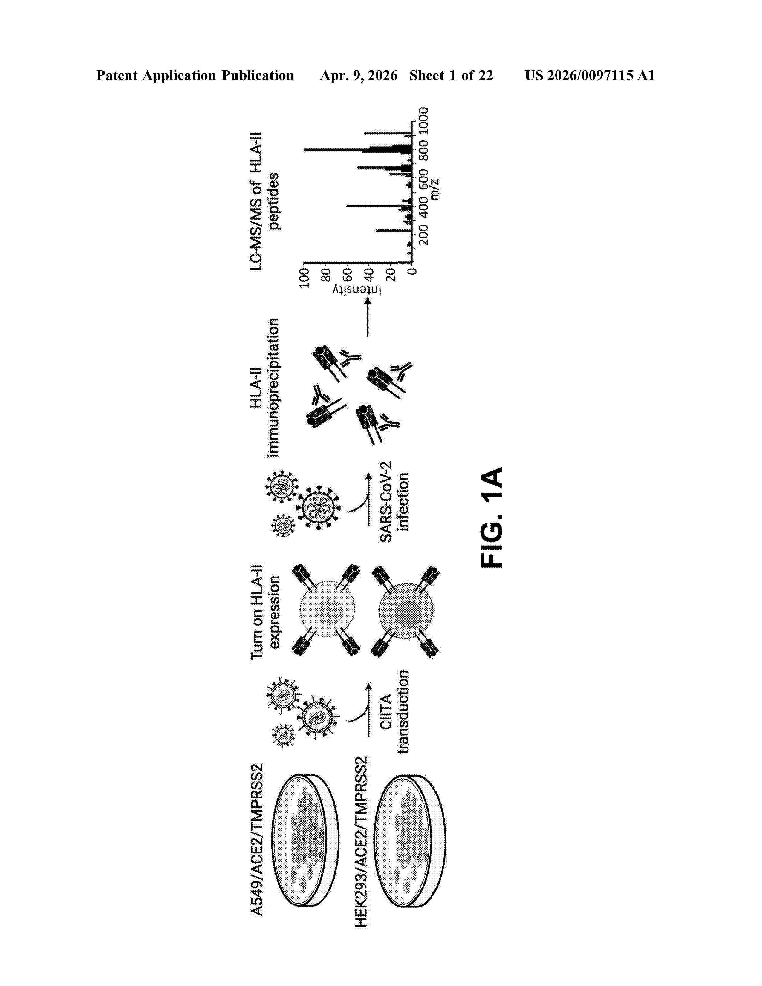
Resumen de: US20260097115A1
0000 Immunogenic compositions comprising one or more peptides, wherein the one or more peptides: are capable of binding to Major Histocompatibility Complex (MHC) class II, and are derived from one or more translation products of SARS-CoV-2. Also provided include methods of treating and preventing diseases using the immunogenic compositions.
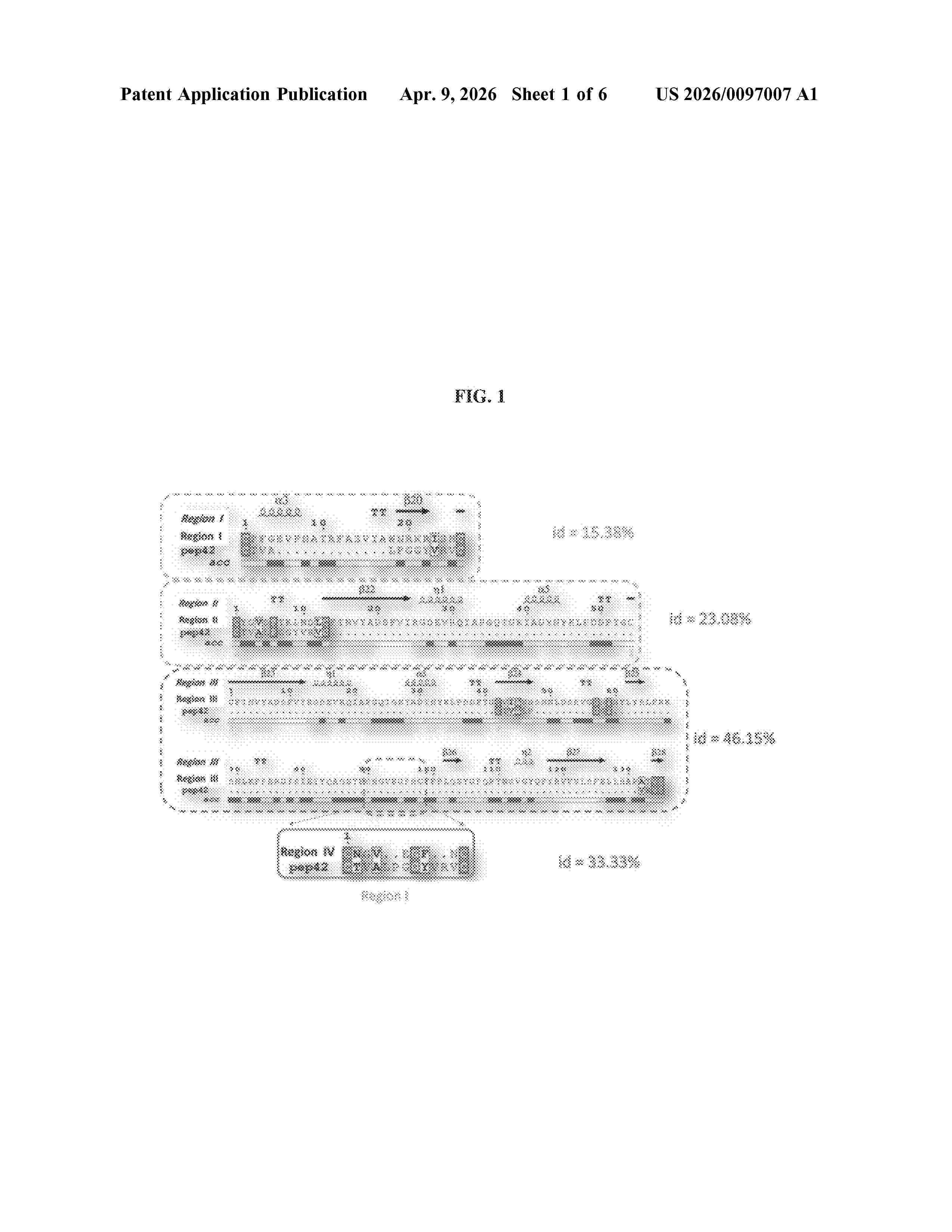
Resumen de: US20260097007A1
0000 Provided herein are methods for the treatment, mitigation, and prevention of viral infections (e.g., coronavirus infections (e.g., severe acute respiratory syndrome coronavirus 2 (SARS-CoV-2), etc.), etc.) and diseases (e.g., Coronavirus disease 2019 (COVID-19)) associated therewith by the administration of cysteamine or derivatives thereof to a subject.
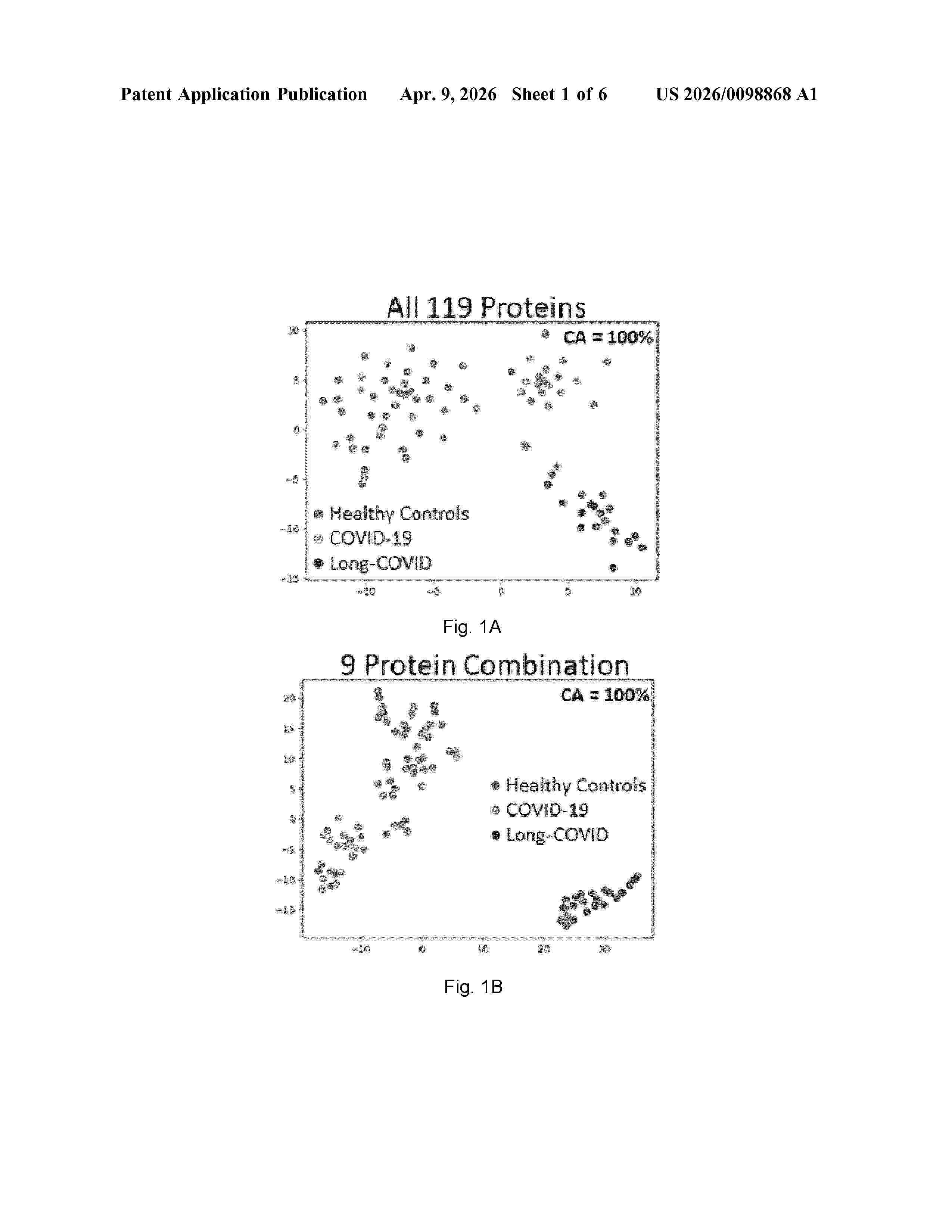
Resumen de: US20260098868A1
A method of diagnosing long-COVID-19 in a patient, the method comprising: (a) obtaining a test sample from the patient, (b) performing one or more assays configured to detect a level of one or more biomarkers in the test sample, (c) comparing the level of the one or more proteins in the test sample with a healthy control reference value of said one or more proteins, wherein a change in the level of the one or more biomarkers in the test sample relative to the healthy control reference value of said one or more proteins is indicative of long-COVID-19 diagnosis, wherein the one or more proteins are selected from Table 3.
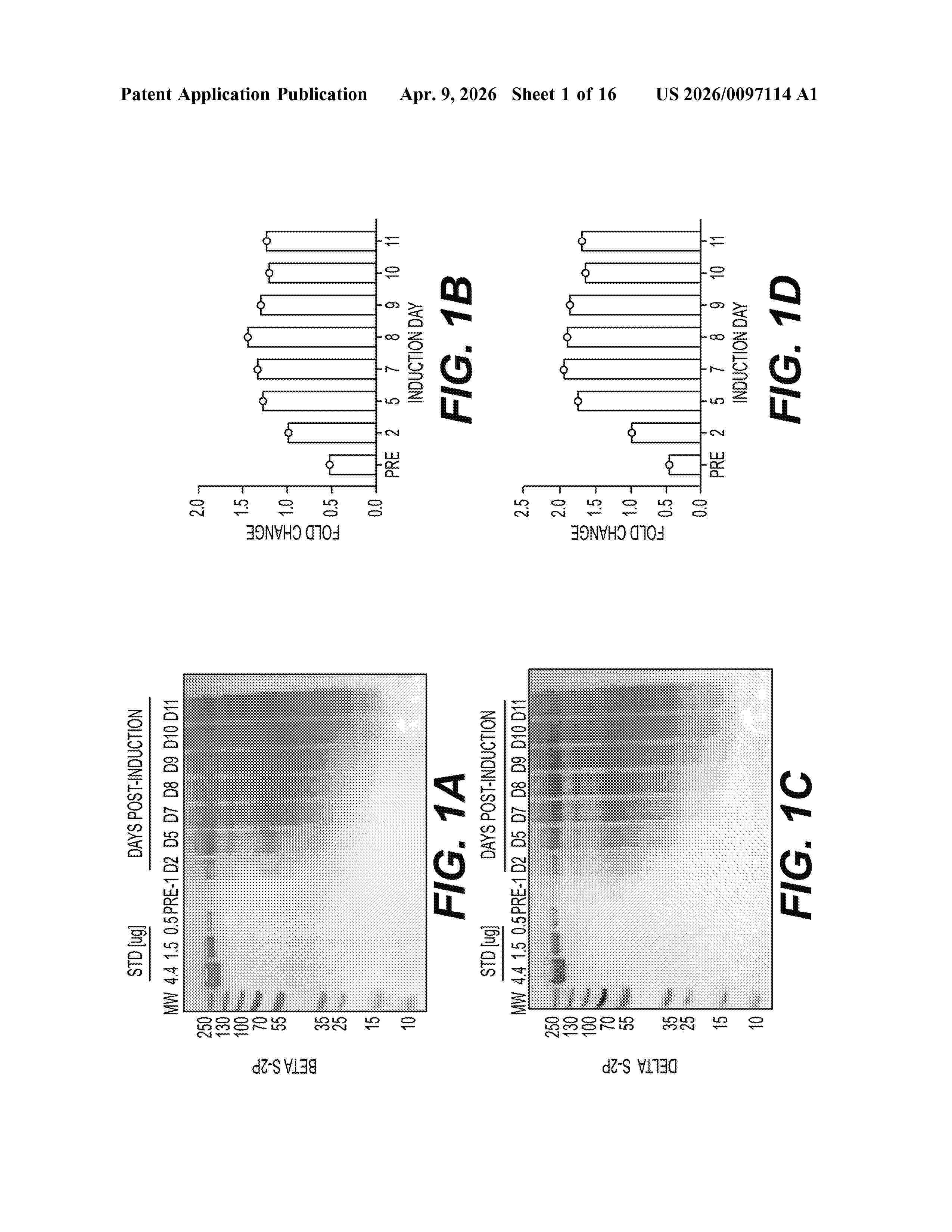
Resumen de: US20260097114A1
The disclosures of the invention are directed to the manufacture of effective, affordable vaccines that are globally accessible. Using a platform conjugation technology, highly immunogenic conjugate vaccines were produced that elicit broad cross-neutralization to variants of concern (VOC), manufactured cheaply compared to mRNA vaccines. Protein-protein conjugates and Toll-Like Receptor (TLR) agonist adjuvants were shown to enhance immunogenicity and induce broad cross-protection against VOC, a characteristic lacking in early mRNA COVID-19 vaccines. Murine nAb titers from Beta-only conjugates were equivalent between Beta, Delta, Omicron BA.1, BA.2, and BA.4/BA.5, which were circulating up to three years after the antigenic strain. Additionally, Beta-Delta bivalent conjugate vaccines readily prevented disease in hamster challenge, which demonstrates a vaccine with remarkably broad cross-protection and potential to protect for extended periods despite mutations, without requiring expensive boosters or antigen adaption. This vaccine can be produced in our highly automated, large-scale manufacturing facility enabling economical production of inexpensive, effective vaccines for high-need areas.
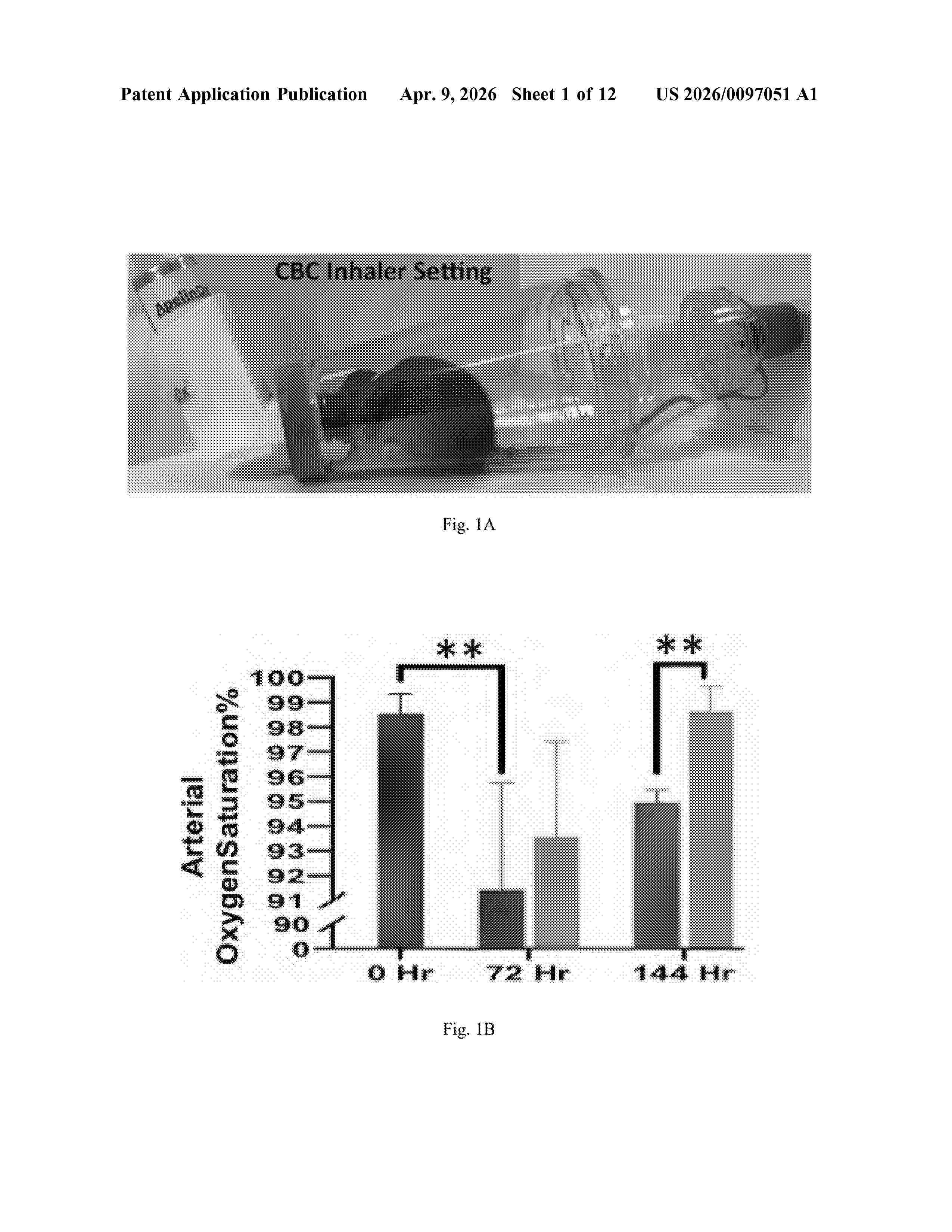
Resumen de: US20260097051A1
Compositions and methods for treating or reducing symptoms of acute respiratory distress syndrome (ARDS) generally and COVID-19 infection, in particular, are provided. An exemplary method includes administering to the subject an effective amount of cannabichromene to reduce acute respiratory distress caused by ARDS generally and COVID-19 infection, in particular.
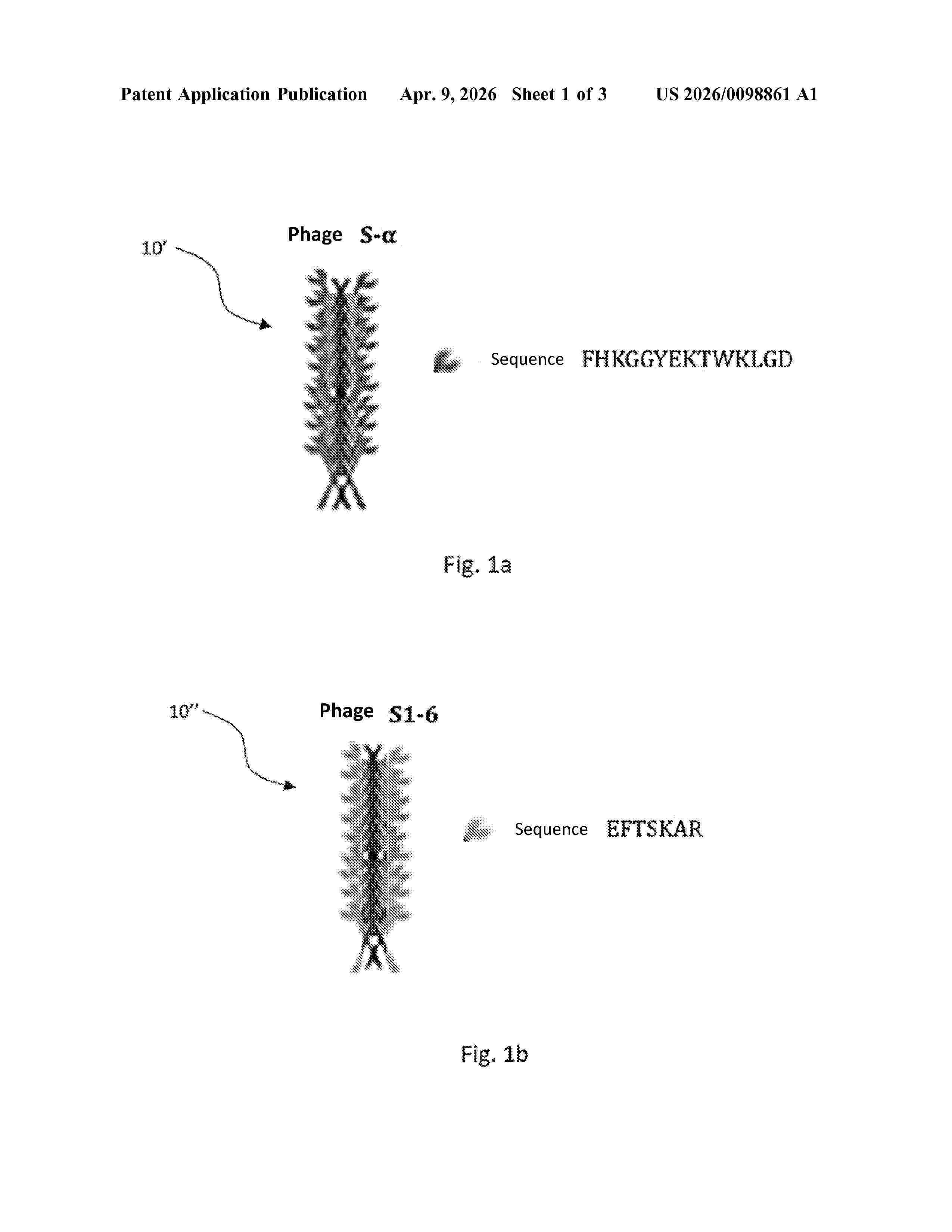
Resumen de: US20260098861A1
A phage for the specific capture of the SARS-CoV-2 virus, said phage being an M13 phage engineered to display on the P8 protein of its coat either FHKGGYEKTWKLGD sequence peptides or EFTSKAR sequence peptides, said peptides having specific affinity for the Spike S1 protein of the SARS-CoV-2 virus.
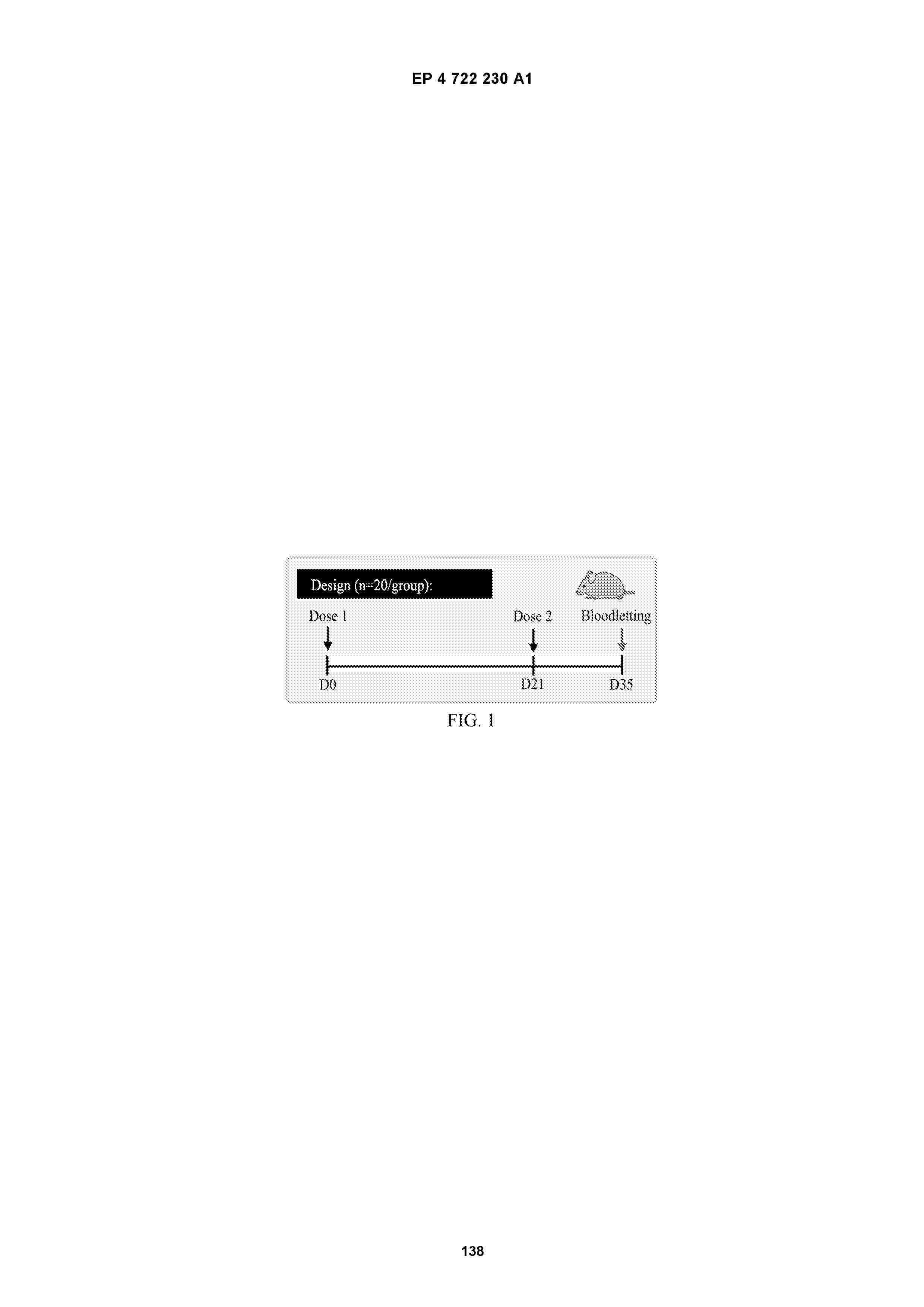
Resumen de: EP4722230A1
0001 The present invention relates to an immunogenic composition comprising a recombinant peptide and protein, wherein the recombinant peptide and protein comprise a coronavirus antigen and immunogen, for example, a chimeric antigen and immunogen of an S protein peptide or a fragment, variant or mutant sequence thereof of SARS-CoV-2 Hu-1, SARS-CoV-2 Omicron (BA.5 and/or XBB.1.5) variant, and/or other variants. The immunogenic composition comprises a secreted fusion protein, which comprises a soluble coronavirus antigen, wherein the soluble coronavirus antigen protein is linked, by means of in-frame fusion, to a C-terminal moiety of a collagen capable of self-trimerization to form a disulfide bond-linked trimeric fusion protein. The immunogenic composition can be used for generating an immune response, and can be used in a vaccine composition. Further provided are methods for producing a recombinant peptide and protein, methods for prevention, treatment and/or diagnosis, and a related kit.
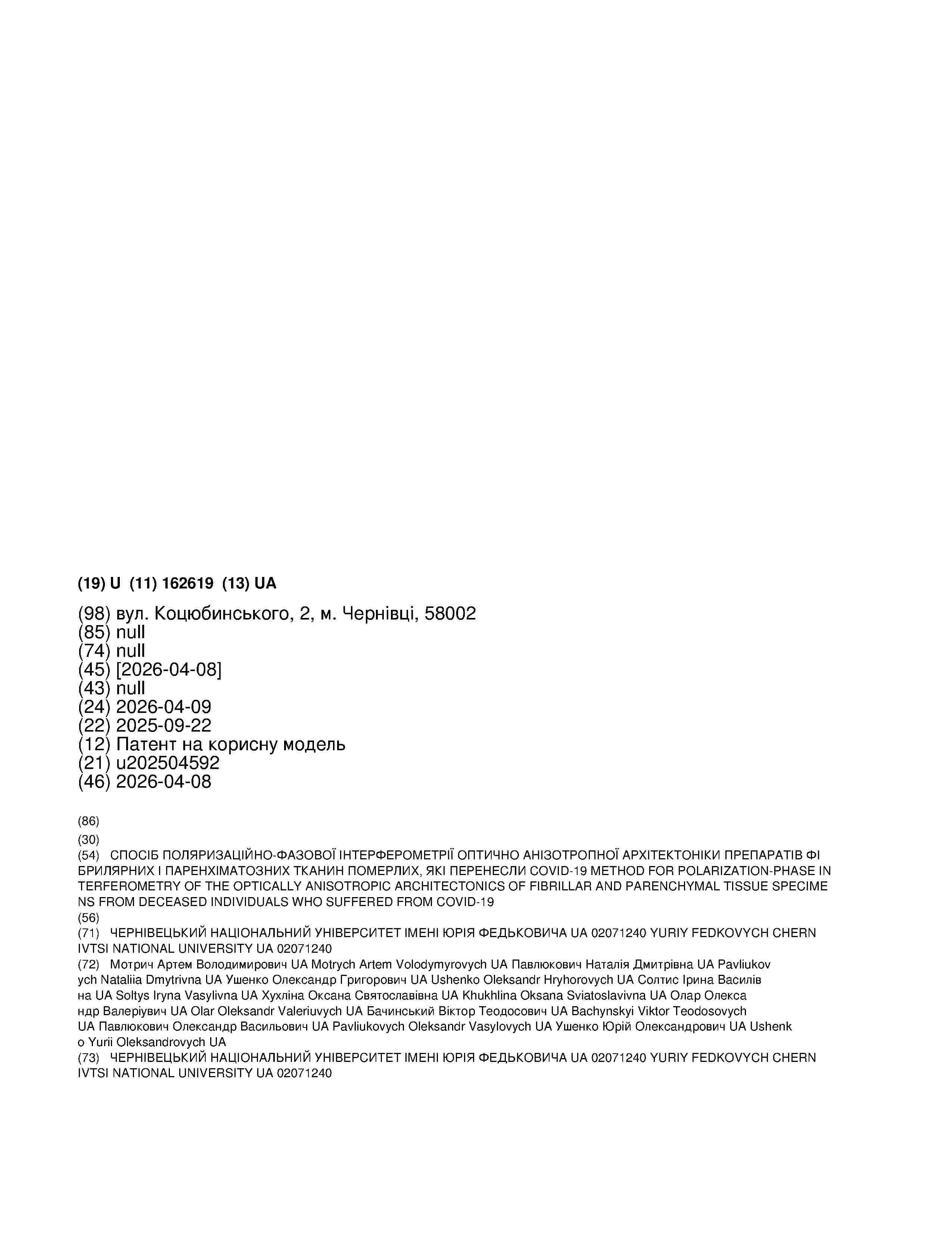
Resumen de: UA162619U
Method for polarization-phase interferometry of the optically anisotropic architectonics of fibrillar and parenchymal tissue specimens from deceased individuals who suffered from COVID-19, by means of polarization mapping of laser microscopic images of native histological sections of biological tissues with algorithmic reconstruction of integrated average phase maps of the polycrystalline architectonics of biological layers through the measurement of coordinate distributions of partial elements of the polarization matrix. To evaluate changes in the layer-by-layer phase maps of the optically anisotropic architectonics of fibrillar (myocardium) and parenchymal (kidney) tissue specimens from the deceased, native histological section samples of deceased individuals who suffered from COVID-19 are placed in the optical beam path of a Mach-Zehnder polarization interferometer. A series of plane-polarized (with polarization azimuths of 0°, 90°, 45°, 135°) and circularly left-hand 5 and right-hand polarized irradiating and reference laser beams are formed; for each polarization state, the irradiating beam is directed by means of a rotating mirror onto the native histological section sample of the deceased who suffered from COVID-19, the laser image of which is projected by a polarization micro-objective into the plane of photosensitive pixels of a digital camera, while a series of reference beams with polarization states of 0°, 90°, 45°, 135°, a, , are sequentially directed by
Nº publicación: EP4722231A1 08/04/2026
Solicitante:
SHANXI JINBO BIO PHARMACEUTICAL CO LTD [CN]
UNIV FUDAN [CN]
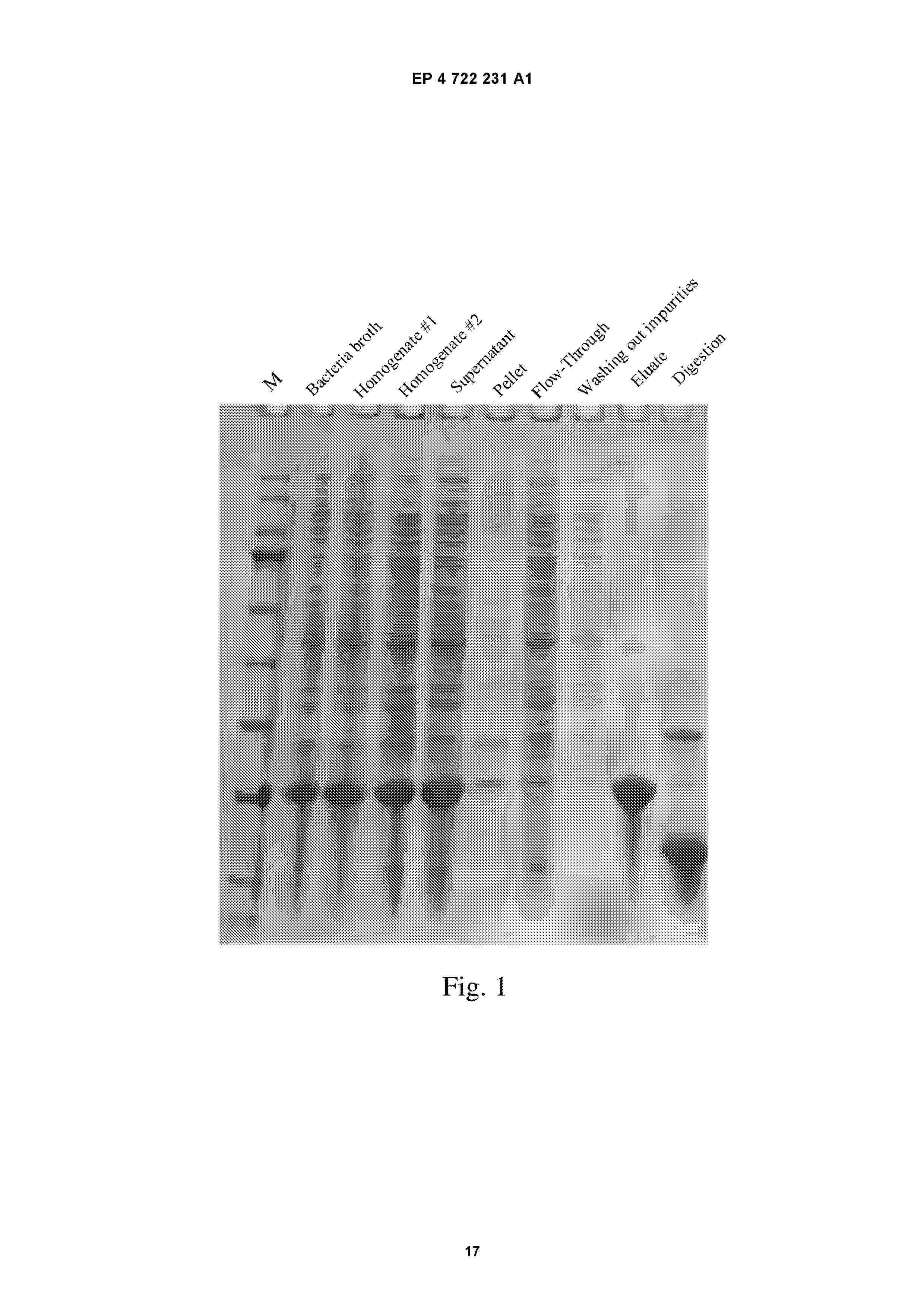
Resumen de: EP4722231A1
A biosynthesis method for a broad-spectrum antiviral polypeptide. The present invention specifically relates to a biosynthesis method for a polypeptide HCoV-EK1 capable of inhibiting human coronavirus infections in a broad-spectrum manner. The specific process comprises: construction of an Escherichia coli genetically engineered bacterium, fermentation culture of the Escherichia coli genetically engineered bacterium, and purification of recombinant polypeptide HCoV-EK1.
 BOPI
BOPI
 Sede Electrónica