Si deseas distinguir tus productos, servicios o ambos de los de otra empresa, es posible que necesites una marca o nombre comercial. Descubre qué son, en qué consiste su procedimiento de registro y qué implica.

Información sobre los plazos de presentación de solicitudes de transformación de marcas de la Unión Europea en marca nacional española. Más información


Si tienes un nuevo dispositivo, producto o procedimiento que resuelva un problema técnico o tenga una ventaja práctica, existen distintas formas de protegerlo en España y en otros países. Descubre cómo hacerlo.

¿Tu innovación reside en la estética, la ornamentación o la apariencia de tu producto? Protégela mediante un diseño industrial. Descubre qué derechos confiere el registro y cómo realizar la tramitación.

Las indicaciones geográficas protegen el nombre de un producto originario de una zona geográfica, a la cual le debe una determinada calidad, reputación u otra característica. Descubre qué son, en qué consiste su procedimiento de registro y qué beneficios conceden.

Las patentes publicadas en todo el mundo son una valiosa fuente de información científica, técnica y comercial.

Si eres emprendedor/a o una empresa y quieres potenciar y mejorar la rentabilidad de tu negocio protegiendo de forma adecuada los activos intangibles de tu organización, en este espacio encontrarás lo necesario.


 789
resultados
789
resultados
 Última actualización
15/09/2026 [08:08:00]
Última actualización
15/09/2026 [08:08:00]


 Resultados 450 a 475 de 789

Resumen de: WO2025012271A1
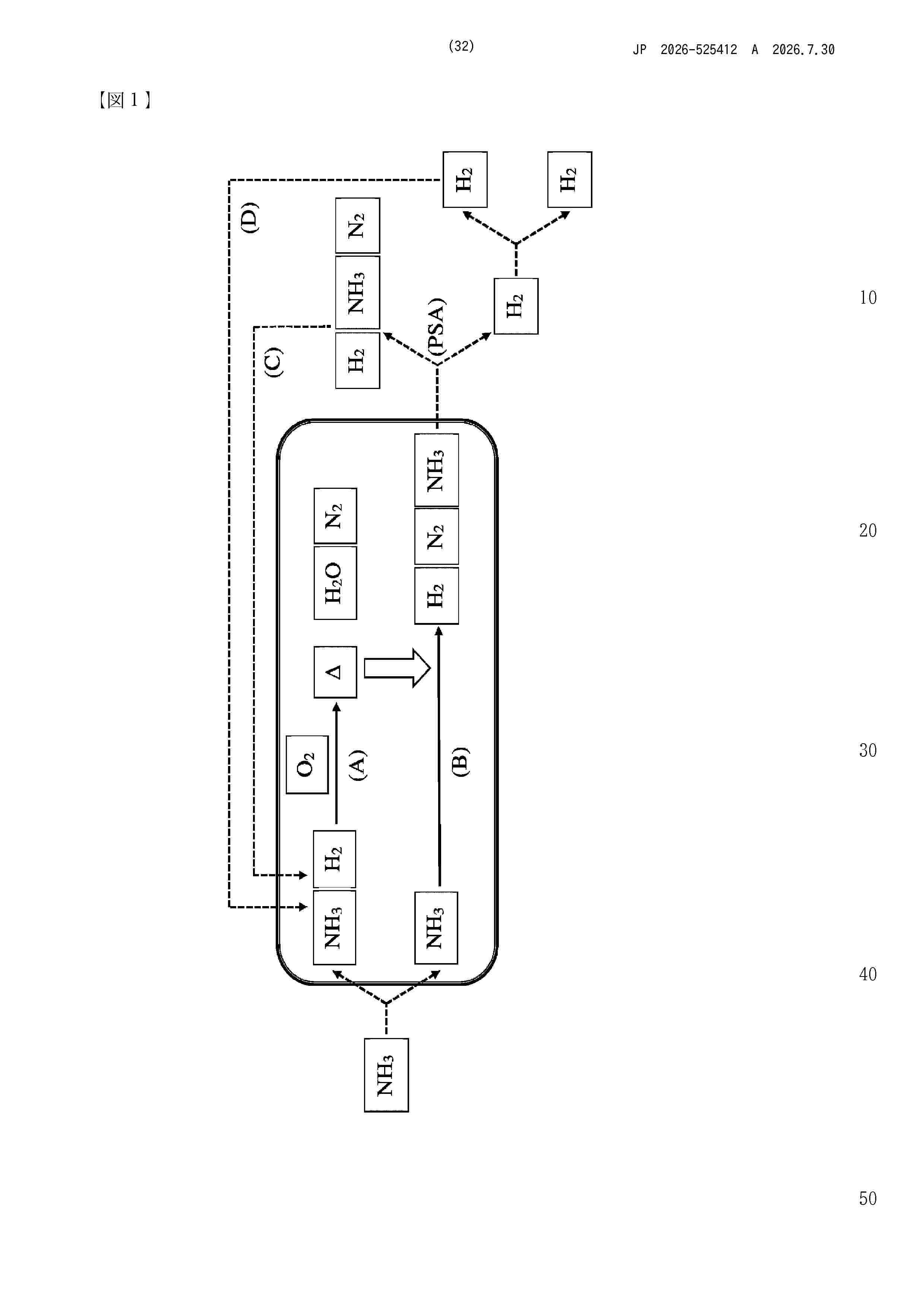
The invention relates to a plant for preparing H2 by catalytically decomposing NH3. The plant according to the invention can be operated in a start-up mode in order to heat apparatuses of the plant to an increased operating temperature using a heat-transfer medium, e.g. following interruption of a continuous operation of the plant due to maintenance work. After heating to the operating temperature, the plant according to the invention can be operated in a production mode for continuous production of H2. The invention also relates to a method for starting up a plant for preparing H2 by catalytically decomposing NH3.

Resumen de: WO2025012277A1
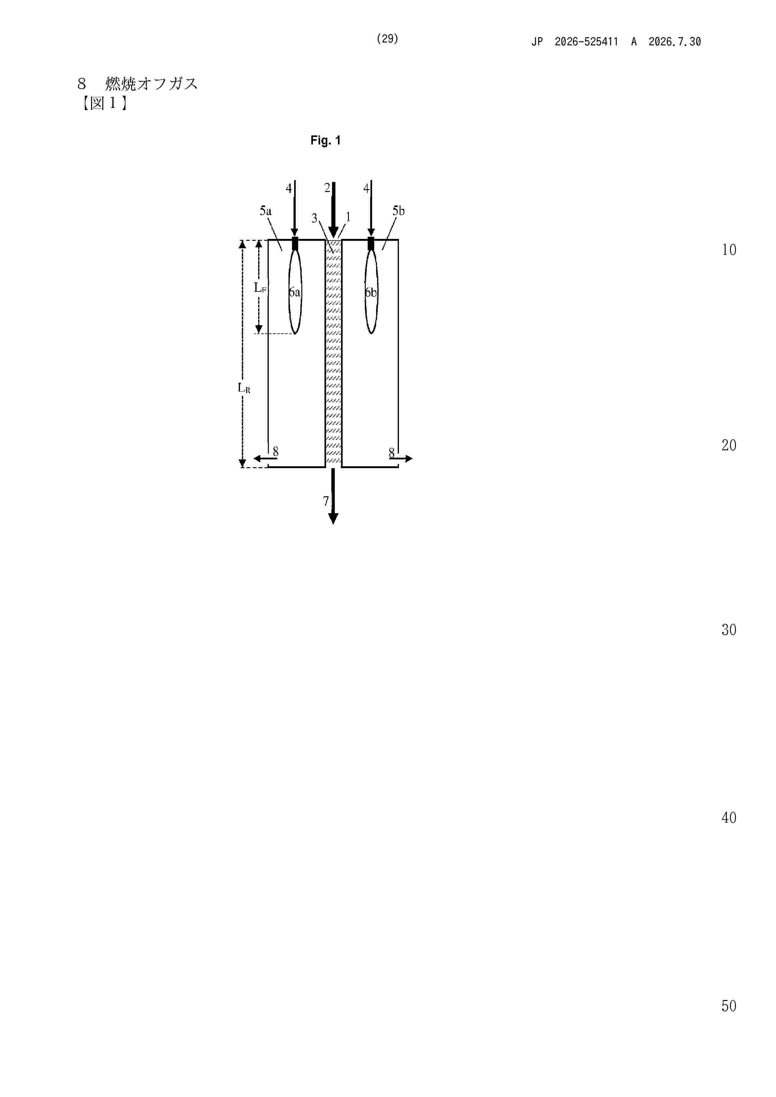
The invention relates to a method for the preparation of H2 from NH3. NH3 is introduced into a fixed-bed reactor at a gas temperature in the range from 550 to 850°C, in which fixed-bed reactor NH3 is decomposed on an NH3 decomposition catalyst partly into H2 and N2. The gas mixture obtained in this manner is discharged from the fixed-bed reactor at a gas temperature in the range from 300 to 700°C, is heated to a temperature in the range from 550 to 700°C and is then introduced into a tubular reactor in which further NH3 is decomposed on a nickel-based NH3 decomposition catalyst into H2 and N2. The gas mixture obtained in this manner is discharged from the tubular reactor at a gas temperature in the range from 550 to 750°C.
Resumen de: US20260218395A1
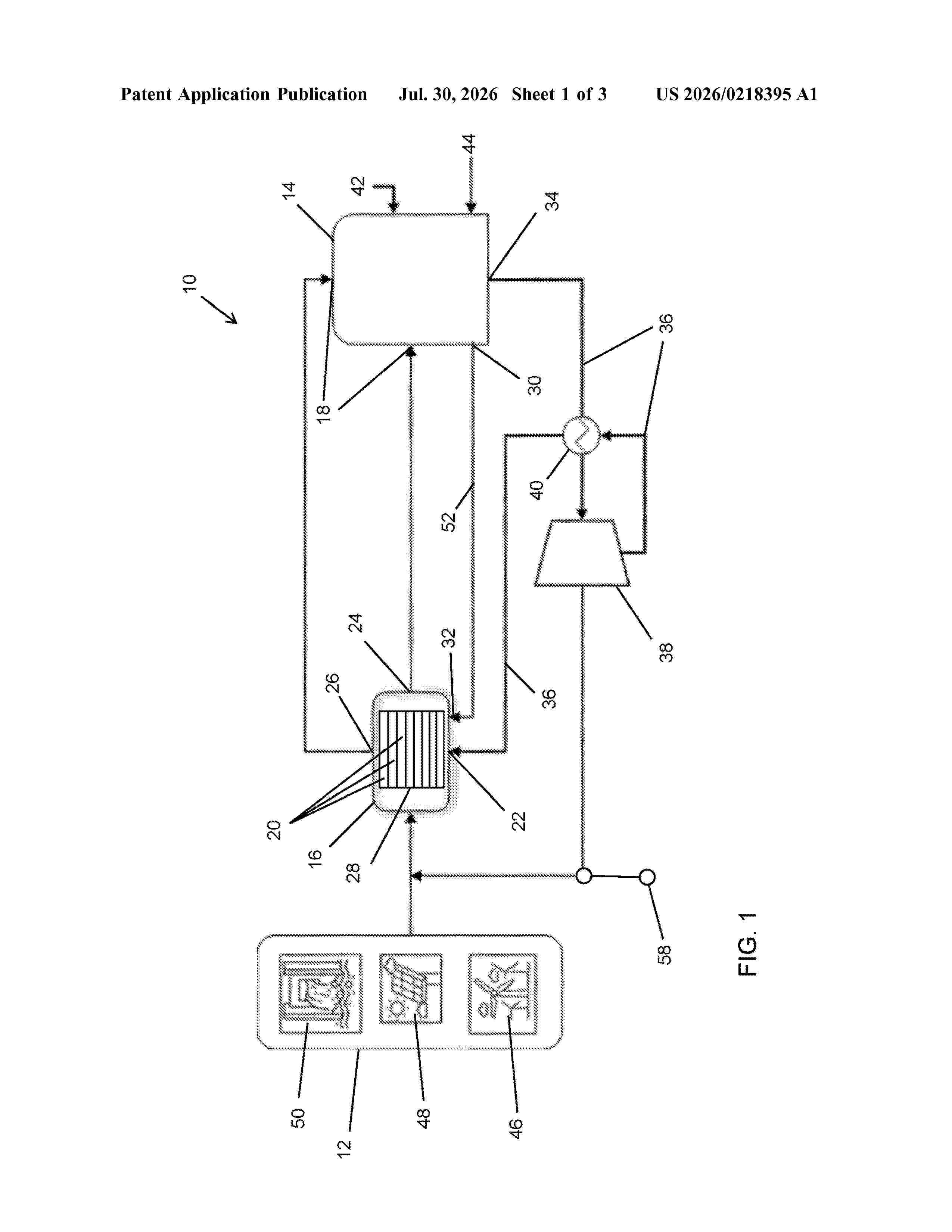
The invention provides an electroly ser system (10) comprising a heat storage unit (14) and an electrolyser (16). The heat storage unit (14) comprises at least one heat source infeed. The electrolyser (16) comprises at least one electrolyser cell (20), a steam inlet and at least one off-gas outlet. The off-gas outlet is connected to the heat source infeed to heat the heat storage unit (14). The heat storage unit (14) is configured to use its stored heat to produce steam for feeding into the steam inlet and for generating electrical power, either one at a time or both at the same time. The invention also provides a system comprising an intermittent or variable electricity source (12) and an electrolyser system (10) as defined above. The intermittent or variable electricity source (12) can be configured to power the electrolyser (16) and to heat the heat storage unit (14) via a heating element, either both at the same time or individually.
Resumen de: US20260218391A1
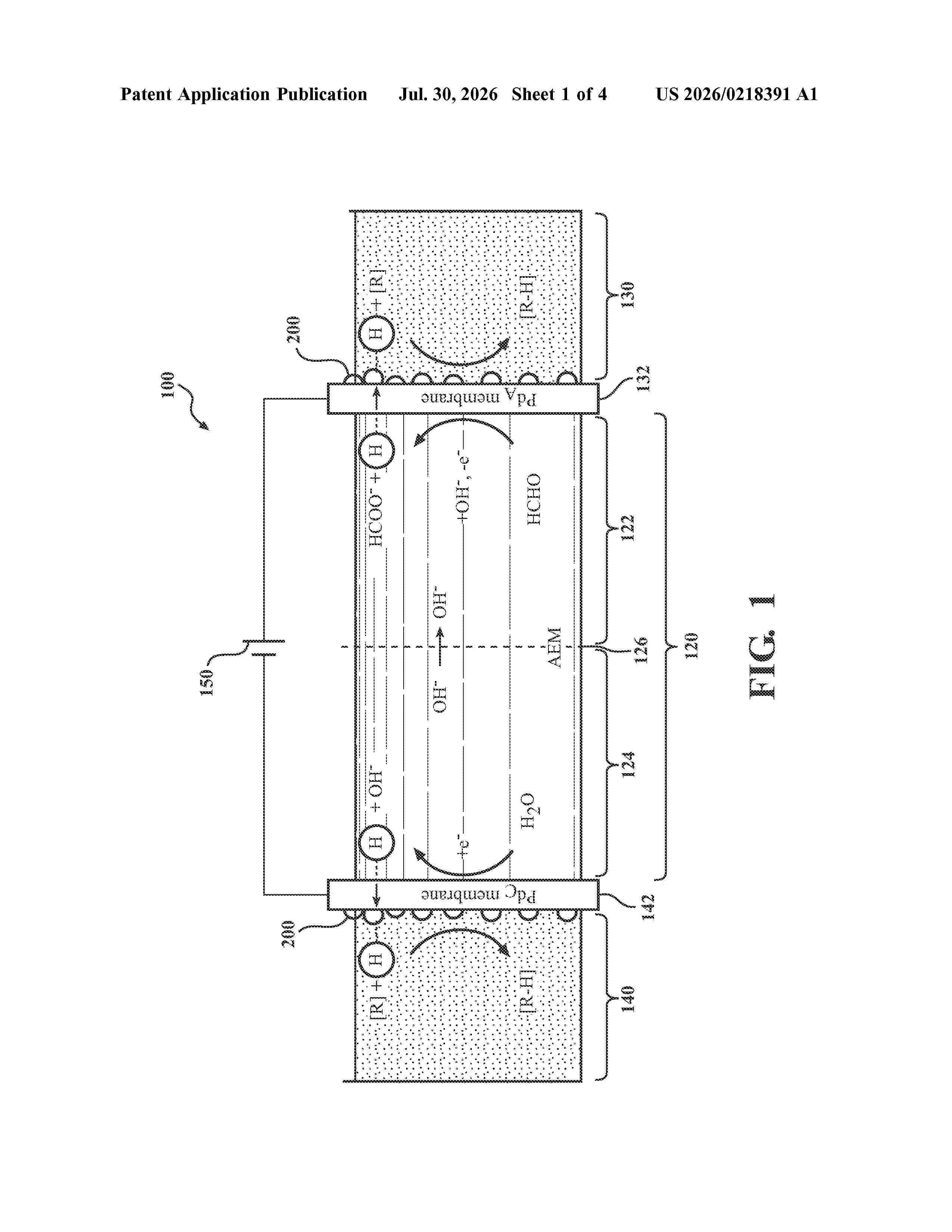
0000 A method of electrocatalytic dual hydrogenation includes loading a first hydrogenation solution and a second hydrogenation solution into a first hydrogenation compartment and a second hydrogenation compartment of an electrocatalytic hydrogenation assembly, in which the first hydrogenation compartment and the second hydrogenation compartment are separated from an electrochemical cell by a hydrogen-permeable anode and a hydrogen-permeable cathode. The method includes applying and maintaining a voltage to the electrochemical cell to reduce a cathode solution and to oxidize an anode solution to provide hydrogen in the cathodic compartment and/or the anodic compartment. The hydrogen may be absorbed through the hydrogen-permeable anode and/or the hydrogen-permeable cathode and hydrogenate an unsaturated substrate in the first hydrogenation solution and/or the second hydrogenation solution. The method includes producing a first hydrogenated product and a second hydrogenated product with a total Faradic efficiency from 150% to 200%.
Resumen de: US20260218066A1
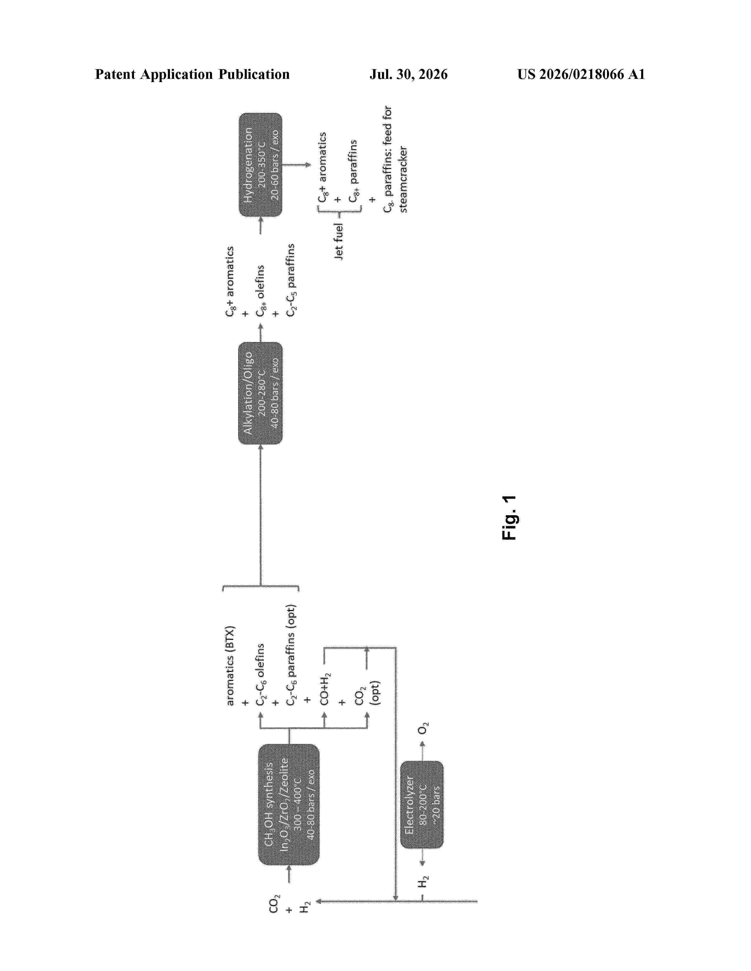
0000 Subject of the invention is a method for producing fuel which comprises C8+ aromatics and C8+ hydrocarbons, the method comprising the steps: (i) converting a feed mixture comprising CO<2 >with H<2 >into a mixture comprising CO, C6+ aromatics and unsaturated C<2>-C<6 >hydrocarbons, wherein the CO<2 >is at least partially converted into methanol using a metal oxide-based catalyst and wherein the methanol is at least partially converted into C6+ aromatics using a zeolite-based catalyst, wherein said unsaturated C<2>-C<6 >hydrocarbons are subsequently at least partially converted into unsaturated C8+ hydrocarbons by oligomerisation, and (ii) alkylating C6+ aromatics from step (i) at least partially with unsaturated C<2>-C<6 >hydrocarbons from step (i) into C8+ aromatics using an acid catalyst different from the zeolite-based catalyst used in step (i).
Resumen de: US20260218394A1
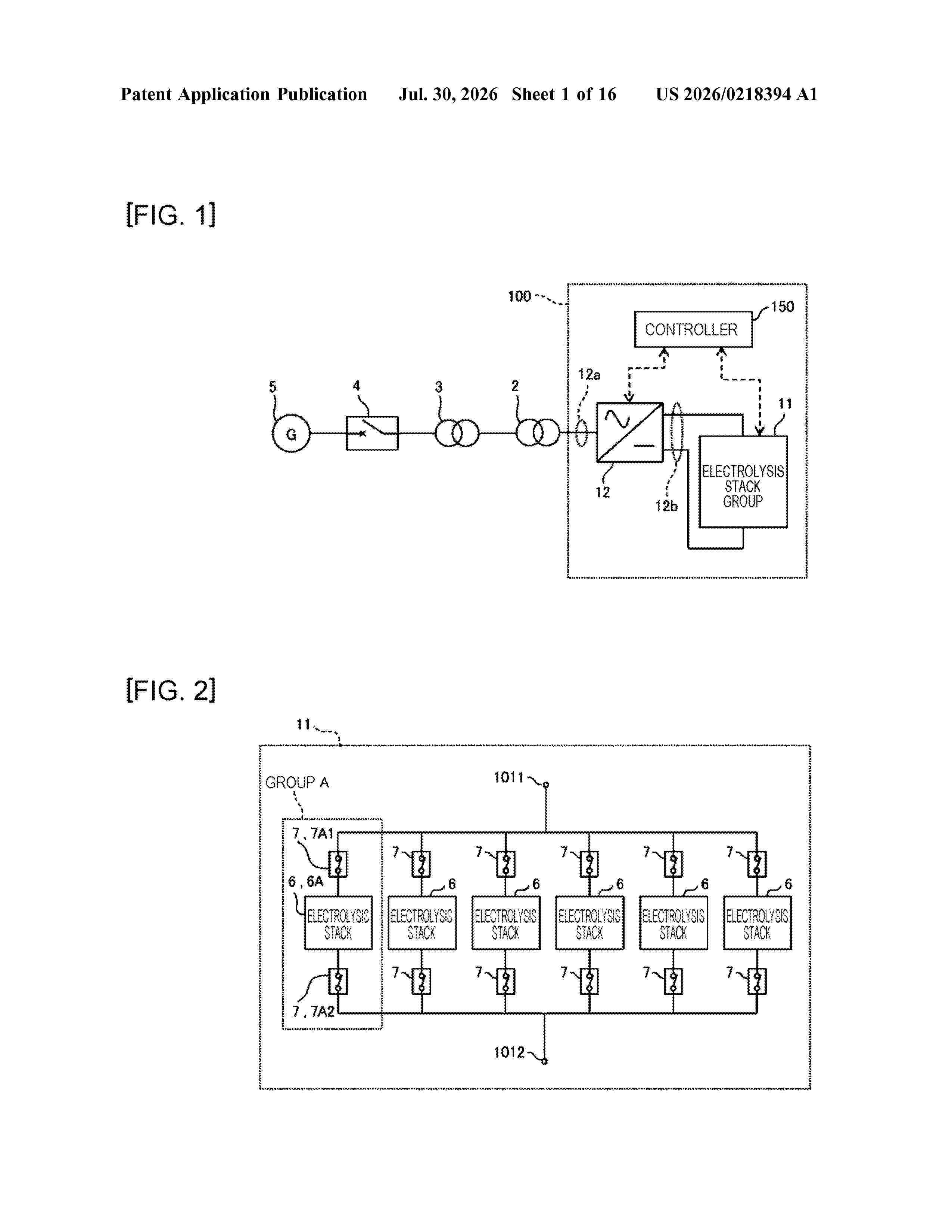
0000 In a water electrolysis system, an AC-side connection end of a power converter is connected to an AC power grid, a series circuit constituted by at least one electrolysis stack and a circuit breaker connected to the at least one electrolysis stack is connected to a DC-side connection end of the power converter, a controller reduces the power flowing to the DC-side connection end before the electrolysis stack is isolated from the series circuit, while maintaining a speed at which the power converter reduces the power flowing to the DC-side connection end below a speed that allows a difference of an amplitude of a voltage of the AC power grid from a reference value to be less than a predetermined value, and when reaching a power level enabling disconnection of an internal DC circuit by the circuit breaker, disconnects the circuit breaker connected to the DC circuit and isolates the electrolysis stack from the series circuit.
Resumen de: WO2026159979A1
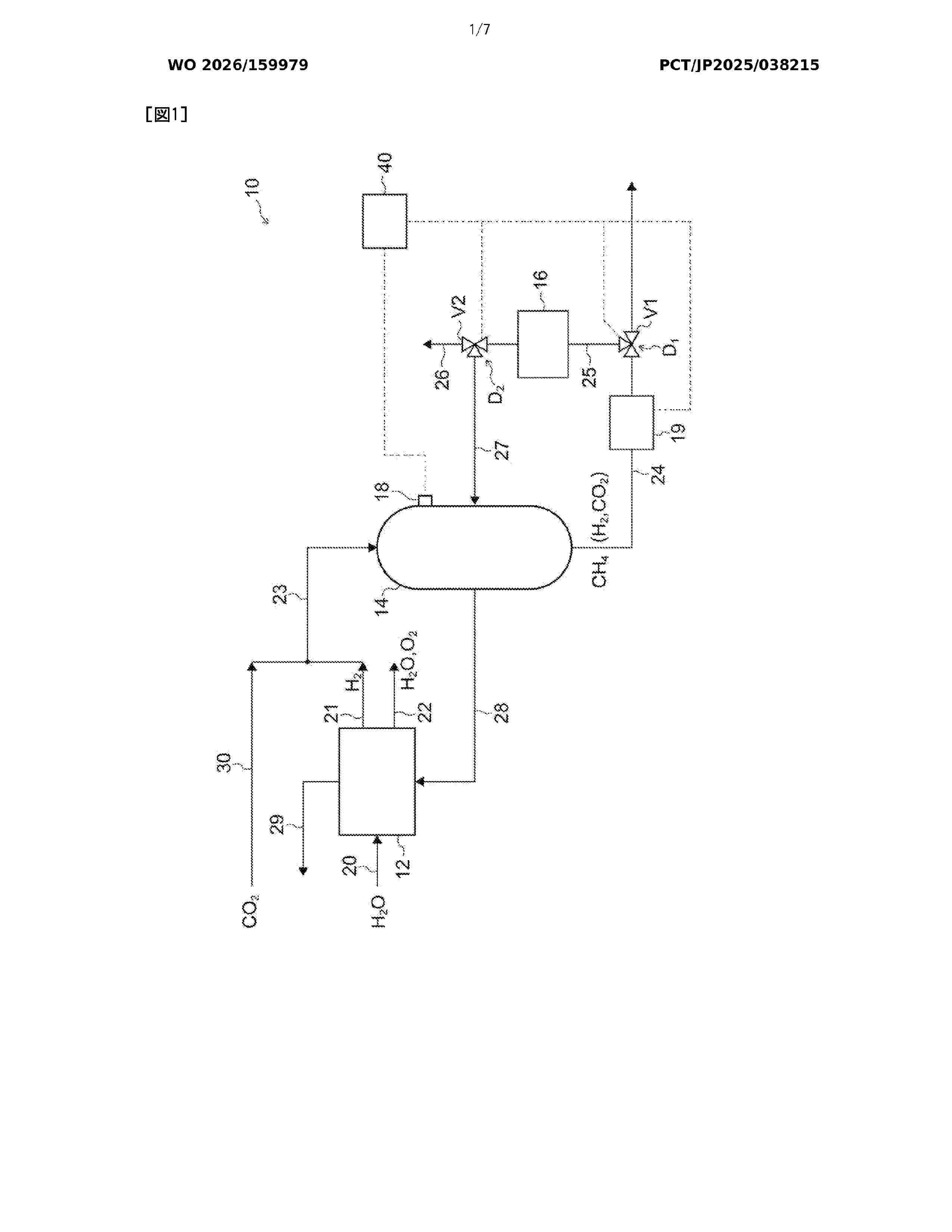
This synthetic fuel generation system comprises: a synthetic fuel generation device that generates a synthetic compound and water by reacting hydrogen and carbon dioxide; a combustion unit that is supplied with a generated gas generated by the synthetic fuel generation device and combusts the generated gas; a heat supply unit that supplies combustion heat in the combustion unit to the synthetic fuel generation device; a generated gas delivery path through which the generated gas is delivered from the synthetic fuel generation device; a combustion supply path that branches from the generated gas delivery path and supplies the generated gas to the combustion unit; and a switching control unit that switches between a combustion mode in which the generated gas is delivered to the combustion supply path and a non-combustion mode in which the generated gas is not delivered to the combustion supply path.
Resumen de: WO2026159980A1
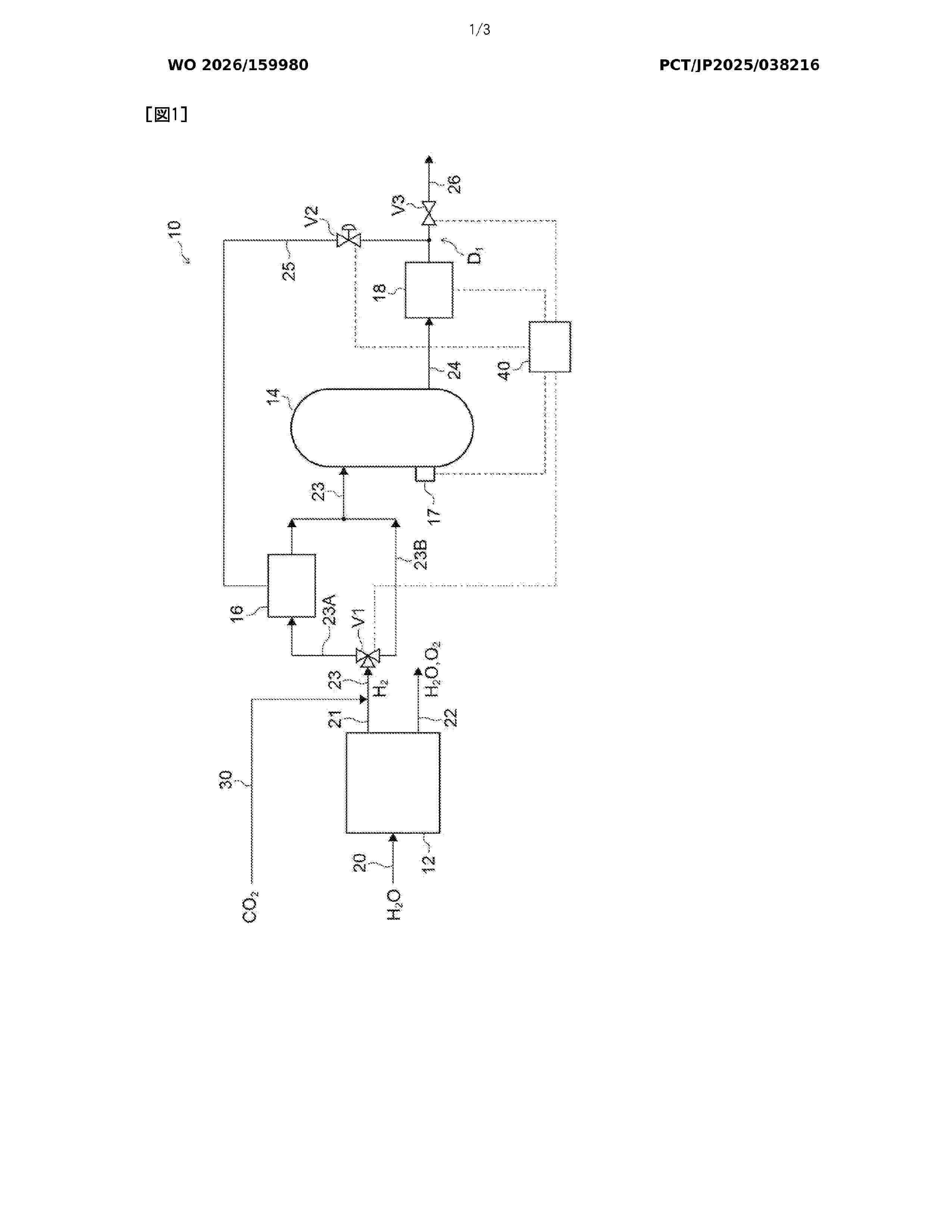
This synthetic fuel generation system comprises: a synthetic fuel generation device that reacts hydrogen and carbon dioxide to generate a synthetic compound and water; a product gas delivery path through which a product gas is delivered from the synthetic fuel generation device; a flowmeter that is provided in the product gas delivery path and measures the flow rate of the product gas; a resupply path that is branched off from the product gas delivery path and returns the product gas to the synthetic fuel generation device; and a switching unit that, when the ratio between the flow rate measured by the flowmeter and the flow rate of the raw material gas supplied to the synthetic fuel generation device exceeds a prescribed ratio, performs switching such that the entire amount of the product gas is delivered to the resupply path when the synthetic fuel generation device is running and such that the amount of the product gas exceeding the flow rate corresponding to the prescribed ratio is delivered to the resupply path when the synthetic fuel generation device is not running.
Resumen de: US20260217529A1
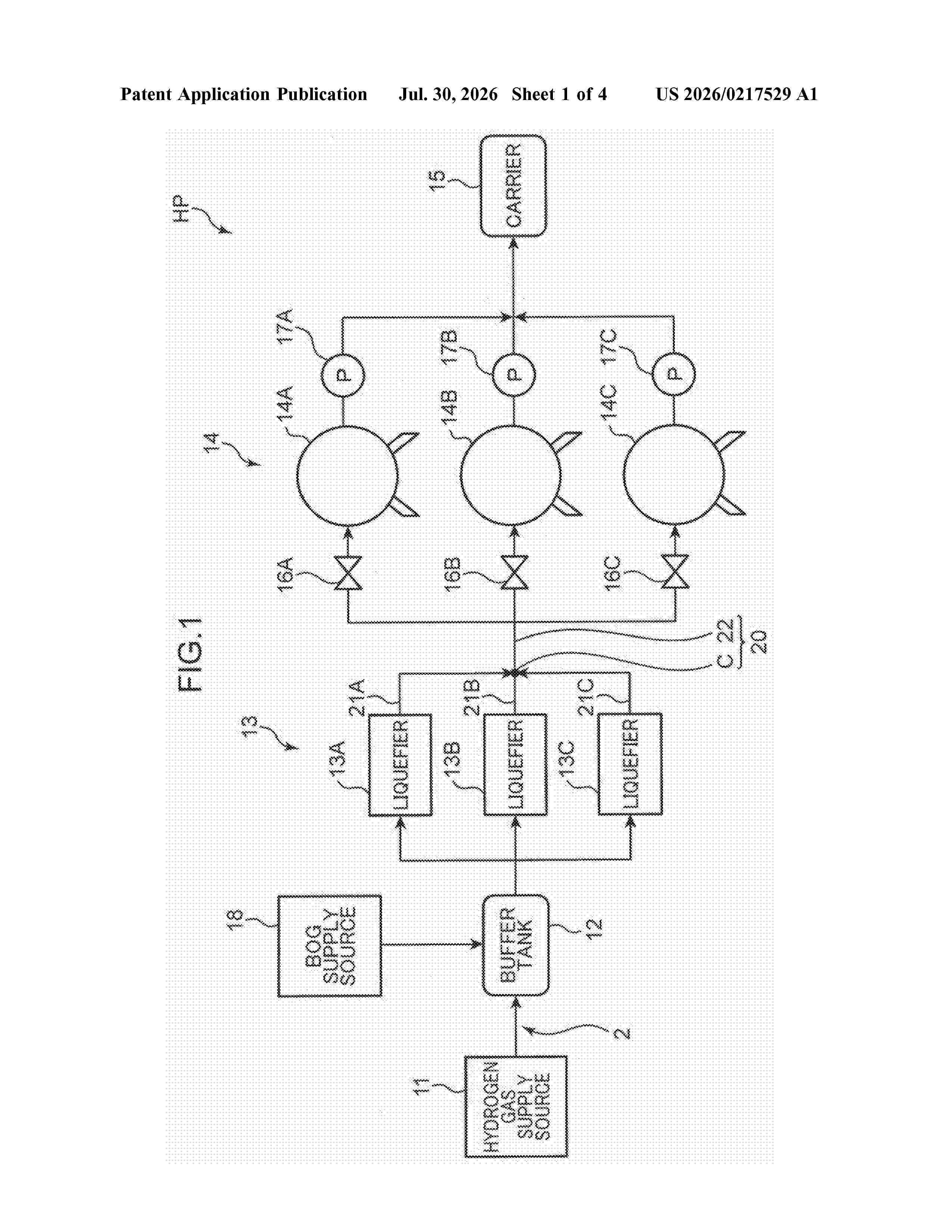
A hydrogen plant includes hydrogen liquefiers, individual pipes, a confluent pipe, and branch pipes. The hydrogen liquefiers convert hydrogen gas into liquefied hydrogen. The individual pipes respectively belong to the hydrogen liquefiers and serve as hydrogen flow passages. The confluent pipe includes a confluence where downstream ends of the individual pipes of the hydrogen liquefiers meet to combine to one, and a collecting pipe located at a downstream position of the confluence. The branch pipes respectively branch from the individual pipes to each take out hydrogen flow having a phase of gas or two phases of liquid and gas.
Resumen de: US20260218071A1
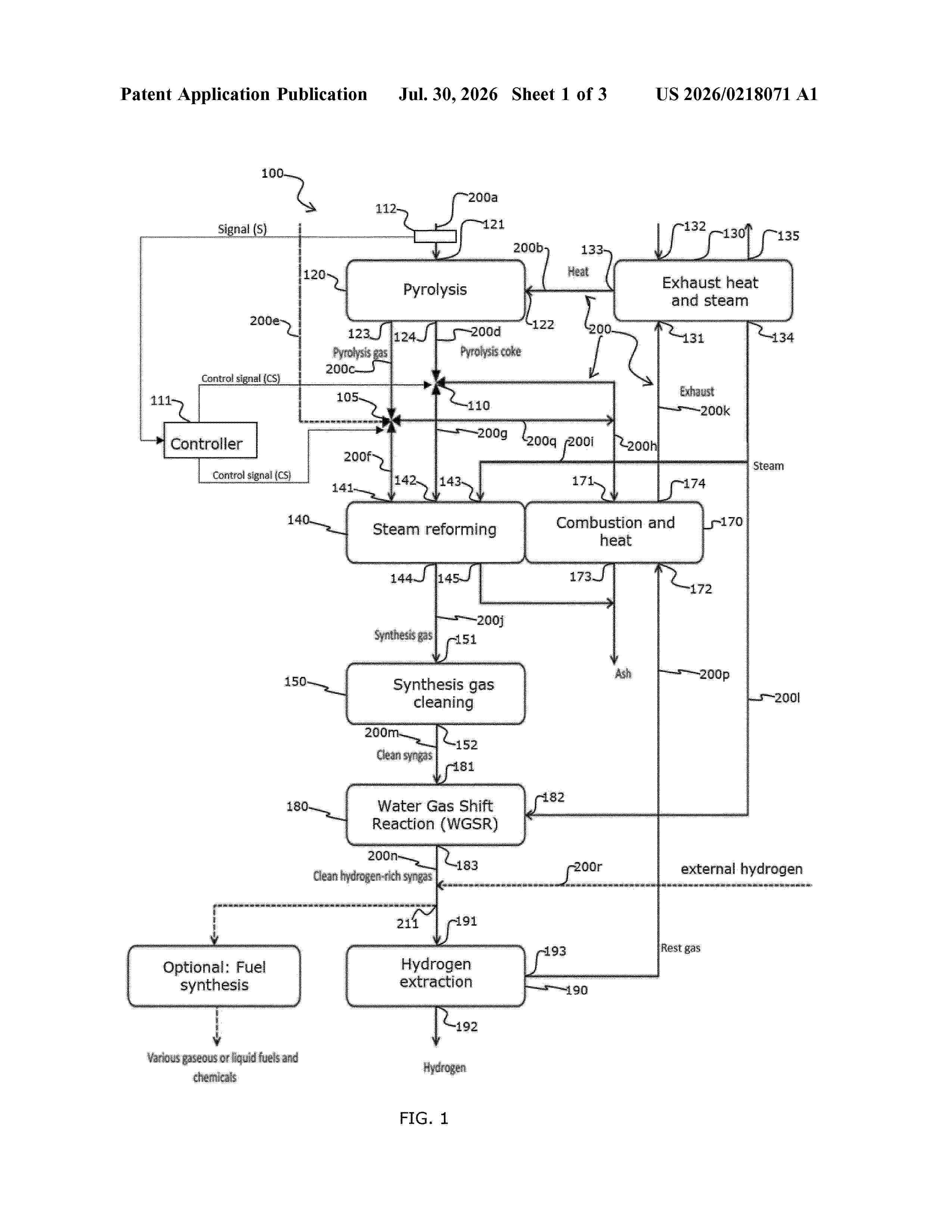
0000 The present disclosure relates to a system for producing hydrogen from feedstock and a method thereof. The system comprises a first chamber adapted to thermally decompose the feedstock, and a second chamber adapted to receive a first portion of the gaseous stream and to receive a first portion of the solids stream to form a reactants combination. The second chamber adapted to partially react the reactants combination with steam to produce a product gas. The system further comprises a third chamber adapted to receive a second portion of the gaseous stream and adapted to receive a second portion of the solids stream to form a combustibles combination. The third chamber adapted to at least partially combust the combustibles combination to produce process heat for the first chamber and/or the second chamber. The system further comprises a controller adapted to adjust the composition of the reactants combination and of the combustibles combination.
Resumen de: US20260218402A1
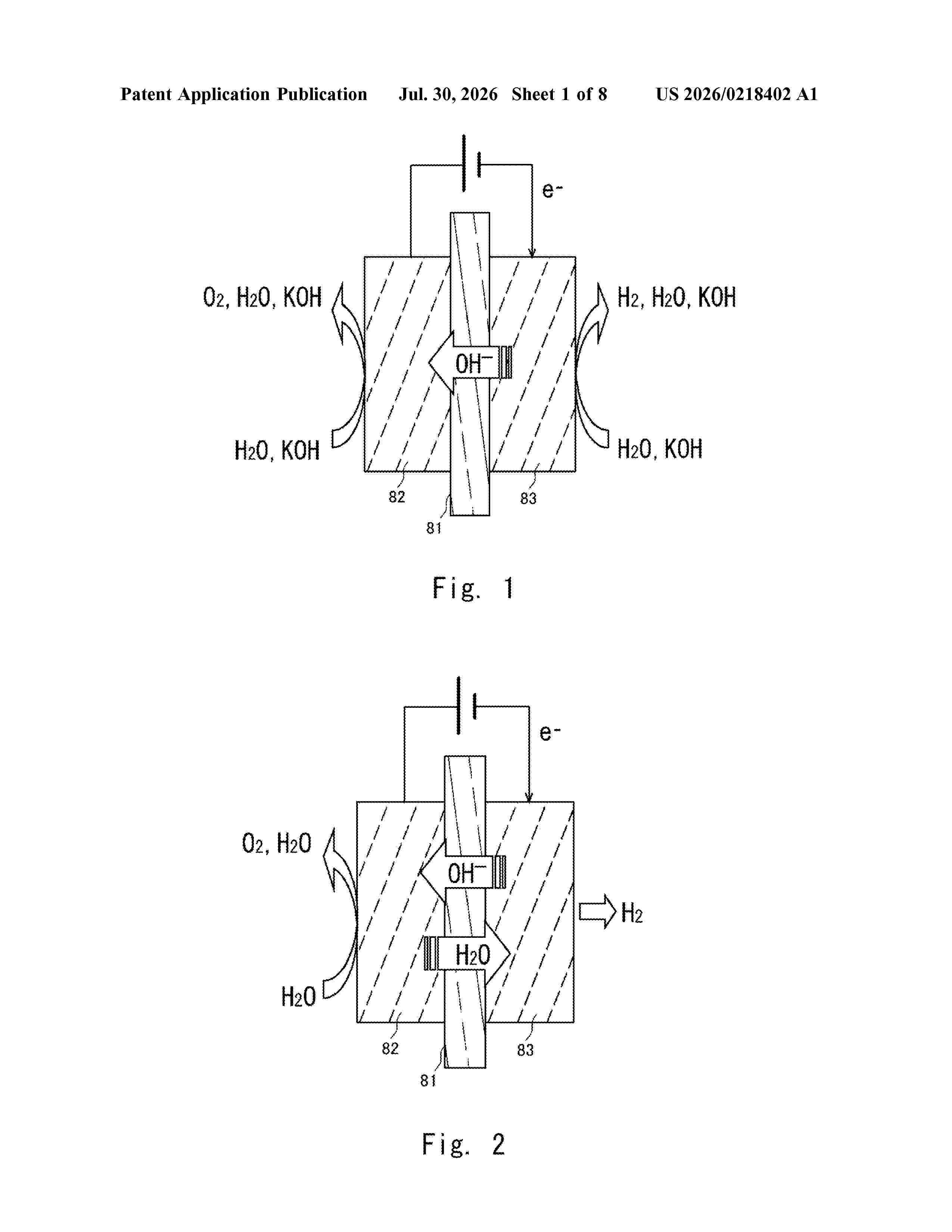
0000 A membrane having excellent radical durability and low gas permeability, a membrane electrode assembly including the membrane, and a water electrolysis apparatus are provided. A membrane having a laminated structure including a layer B1, a layer A, and a layer B2 in this order, in which the layer A contains a hydrocarbon-based polymer (a) which has an ionic group and may be fluorine-substituted, and each of the layers B1 and B2 contains a perfluoro-carbon polymer (b) having an ionic group.
Resumen de: US20260218401A1
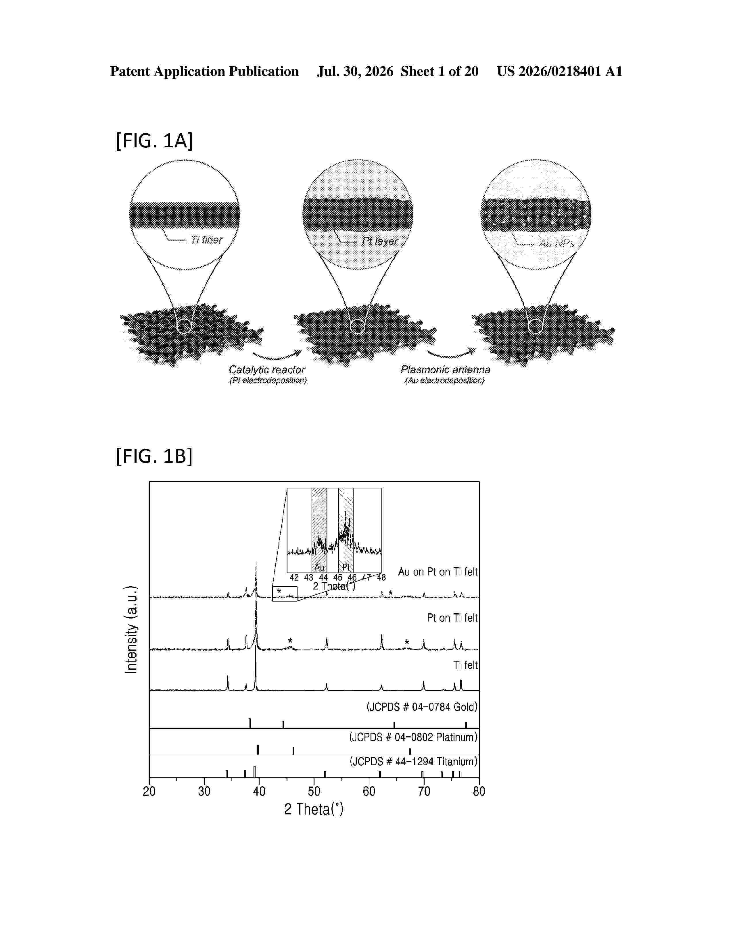
The present disclosure relates to a hybrid electrode including plasmonic nanoparticles and an electrolysis system including the same. The hybrid electrode and the electrolysis system including the same according to embodiments of the present disclosure may utilize a plasmonic-active (antenna–reactor) composite electrode to re-activate a catalyst surface via plasmonic phenomena during an electrochemical reaction.
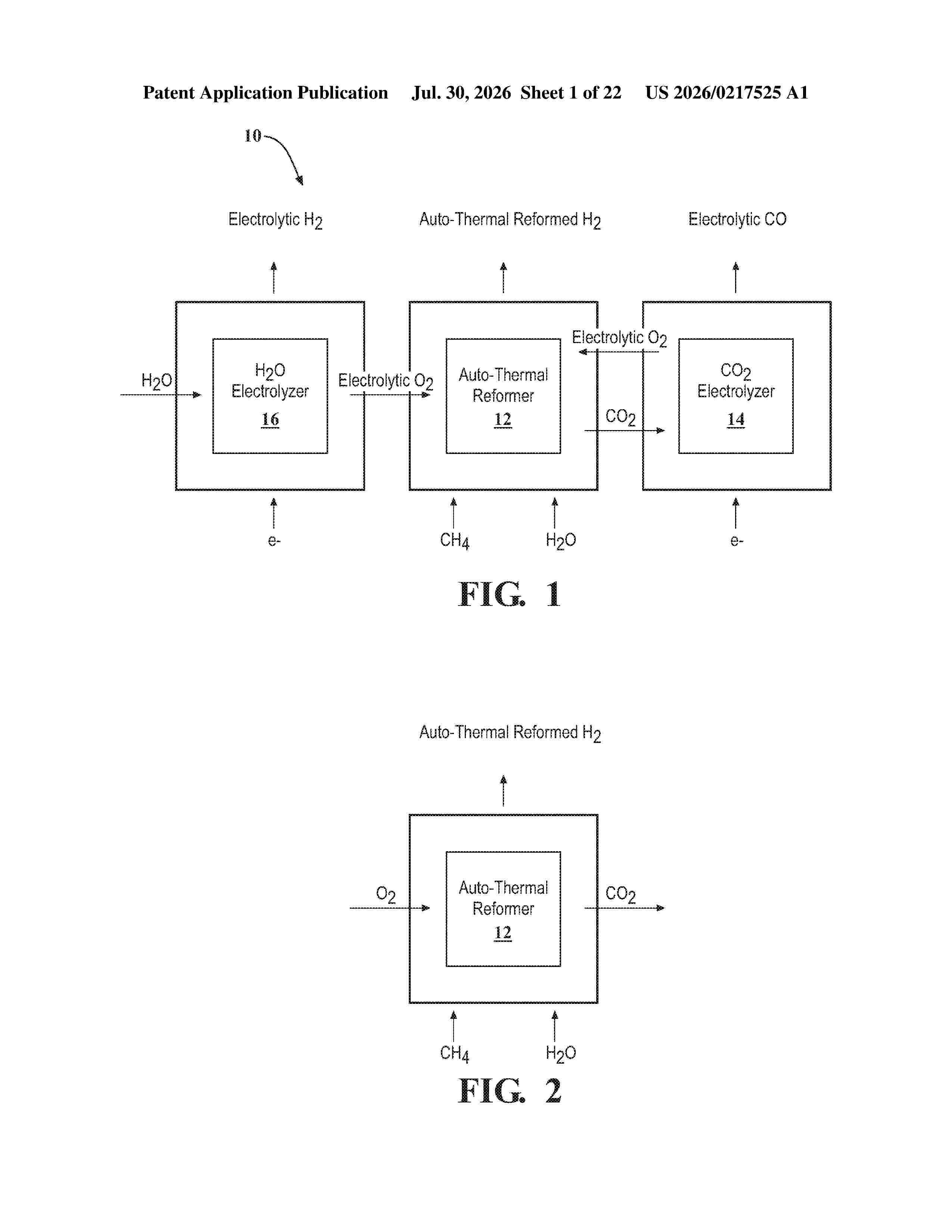
Resumen de: US20260217525A1
A system and method for producing low-cost, low to zero-carbon, and emission-free hydrogen (H2) is provided. The system includes an auto-thermal reformer which uses electrolytic oxygen (O2), a hydrocarbon fuel source, and water (H2O) to perform a partial oxidation reaction and produce auto-thermal reformed hydrogen and carbon dioxide (CO2). The system also includes a carbon dioxide electrolyzer for receiving electricity and the carbon dioxide from the auto-thermal reformer, and performing electrolysis on the carbon dioxide. The carbon dioxide electrolyzer produces electrolytic carbon monoxide (CO) and a portion of the electrolytic oxygen provided to the auto-thermal reformer. The system also typically includes a water electrolyzer, which performs water electrolysis to produce electrolytic hydrogen and more electrolytic oxygen which can be provided to the auto-thermal reformer. In addition, the carbon monoxide produced by the carbon dioxide electrolyzer can be combined with the hydrogen produced by the auto-thermal reformer to form syngas.
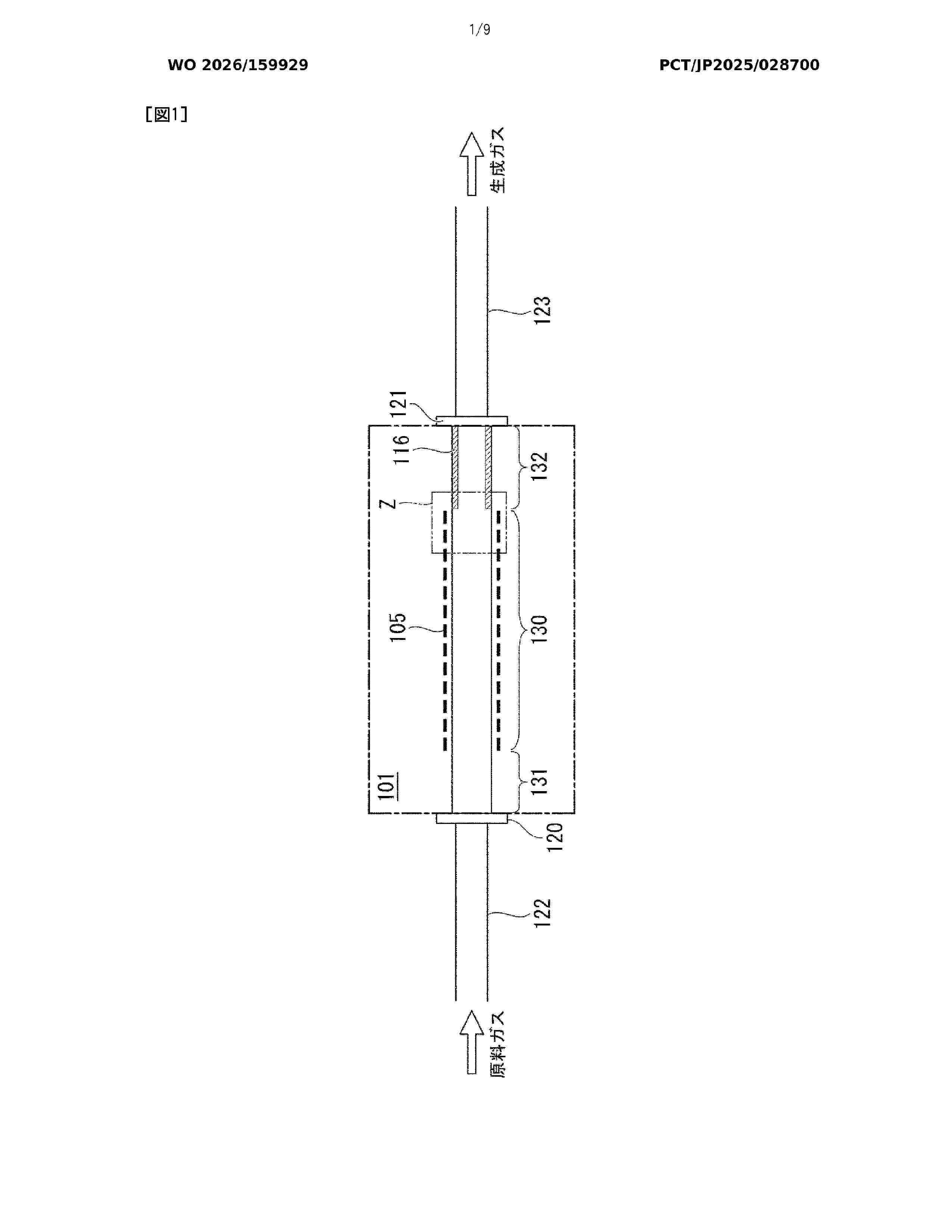
Resumen de: WO2026159929A1
Provided are an electrolysis cell stack, an electrolysis cell cartridge, an electrolysis cell module, and a method for producing an electrolysis cell stack which make it possible to suppress a decrease in H2/CO yield, even when a methanation catalyst is contained in a flow passage through which a generated gas generated by a hydrogen electrode via co-electrolysis flows. An electrolysis cell stack (101) according to the present disclosure comprises: an electrolysis cell (105) in which a hydrogen electrode (109), a solid electrolyte (111), and an oxygen electrode (113) are stacked, in this order; a flow passage (117) through which a generated gas generated by the hydrogen electrode flows; and a methanation suppression film (116) that covers the surface of a member (103), which defines the outer contour of the flow passage, on the side thereof on which the generated gas flows. The member defining the outer contour of the flow passage contains a methanation catalyst, and the methanation suppression film does not contain a methanation catalyst.
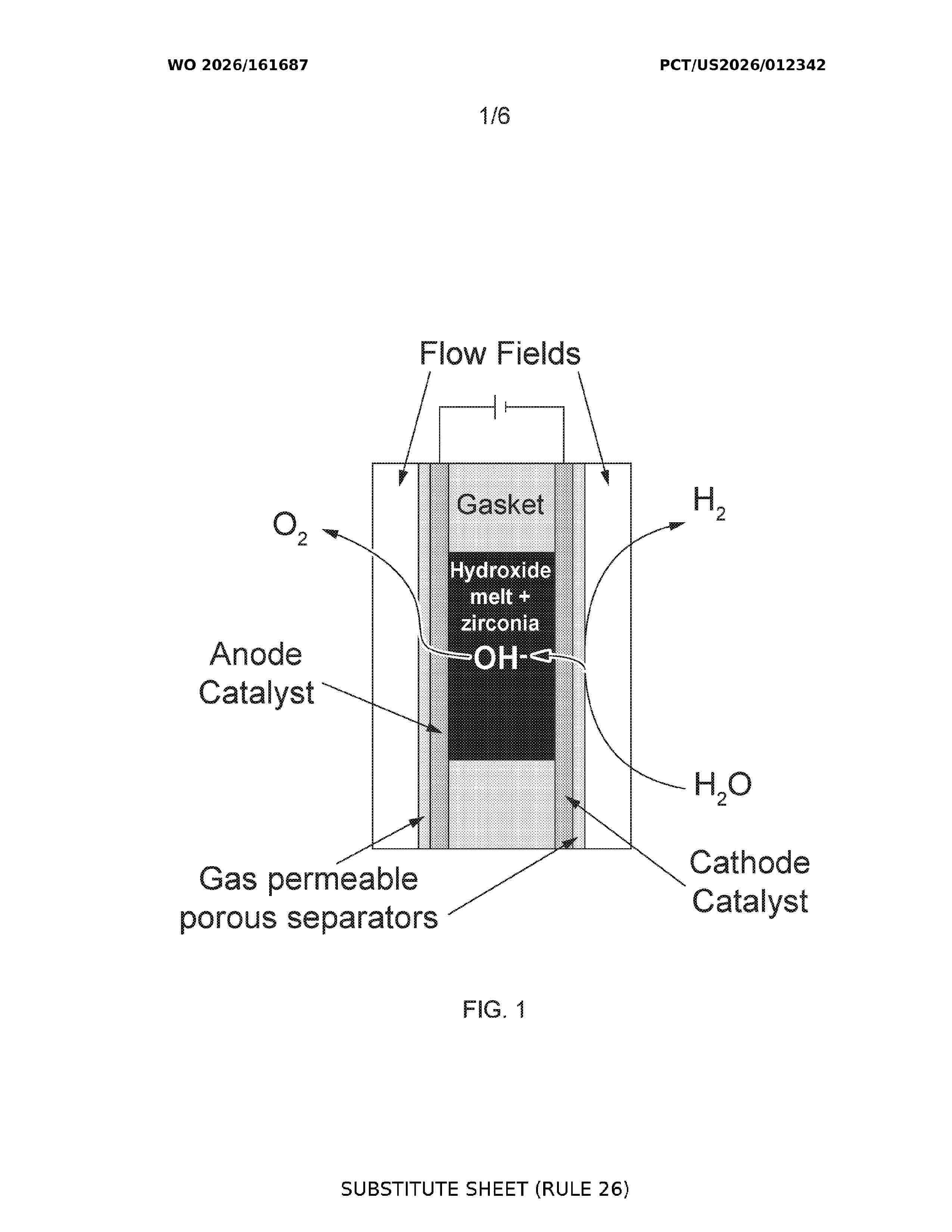
Resumen de: WO2026161687A1
Disclosed is an electrolyzer, comprising: a cathode, comprising a cathode catalyst and a cathode separator; an anode, comprising an anode catalyst and an anode separator; a cathode flow field, comprising an inlet and an outlet; wherein the cathode flow field is in contact with the cathode; an anode flow field, comprising an inlet and an outlet; wherein the anode flow field is in contact with the anode; and an electrolyte wherein the cathode separator and the anode separator each independently comprise a porous hydrophobic material. Also disclosed are methods of producing H2 and O2 using the electrolyzer.
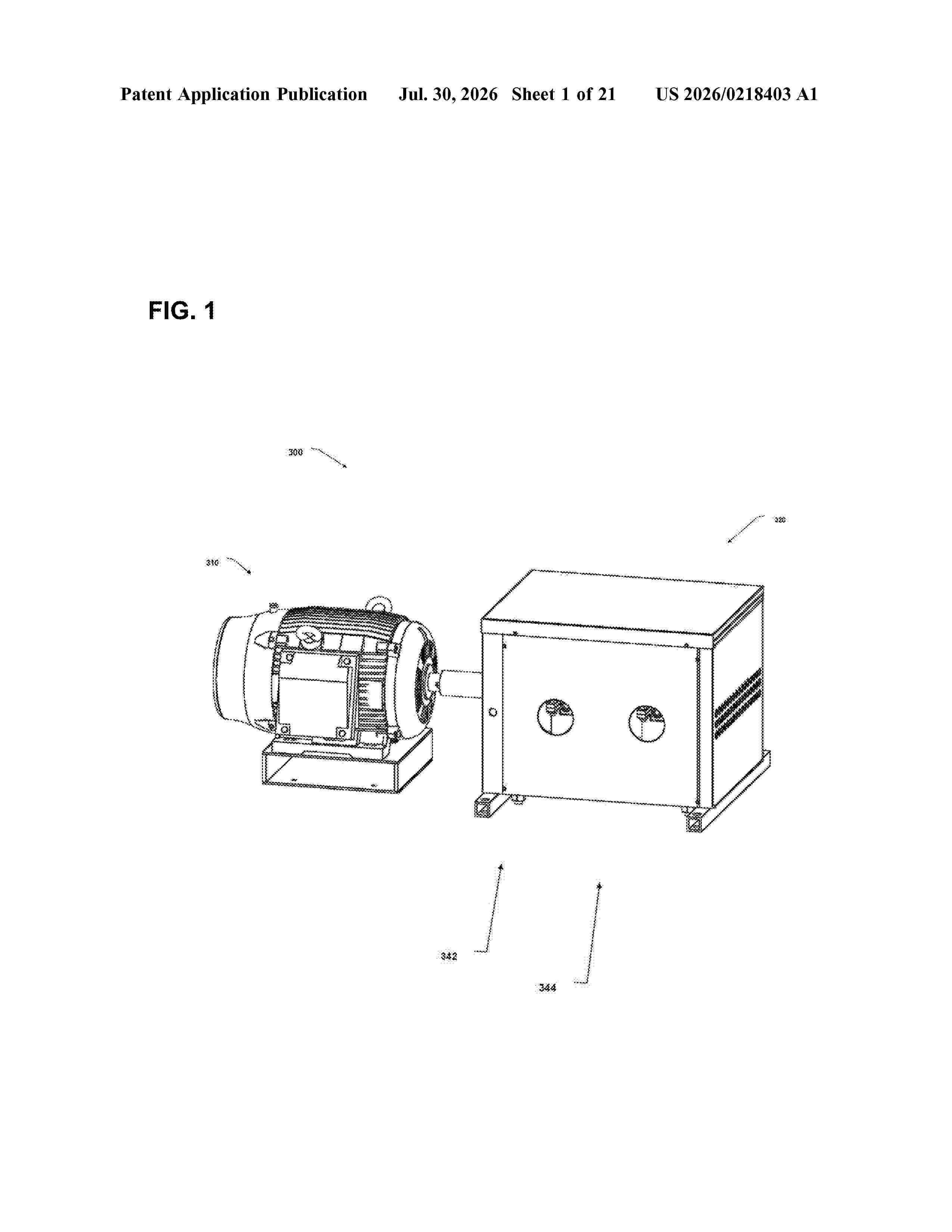
Resumen de: US20260218403A1
An ion separator is used to produce a stream of positively charged electrolytes and another stream of negatively charged electrolytes with adequate potential difference between the two streams. Short-circuiting these two streams in gas generation chambers produces hydrogen and oxygen gases. This setup of equipment is assembled as a containerized hydrogen and oxygen production cell. An x-y grid layout of many containerized hydrogen and oxygen production cells is used to outline a scalable plant for manufacturing oxygen and green hydrogen in large quantities.
Resumen de: WO2026160583A1
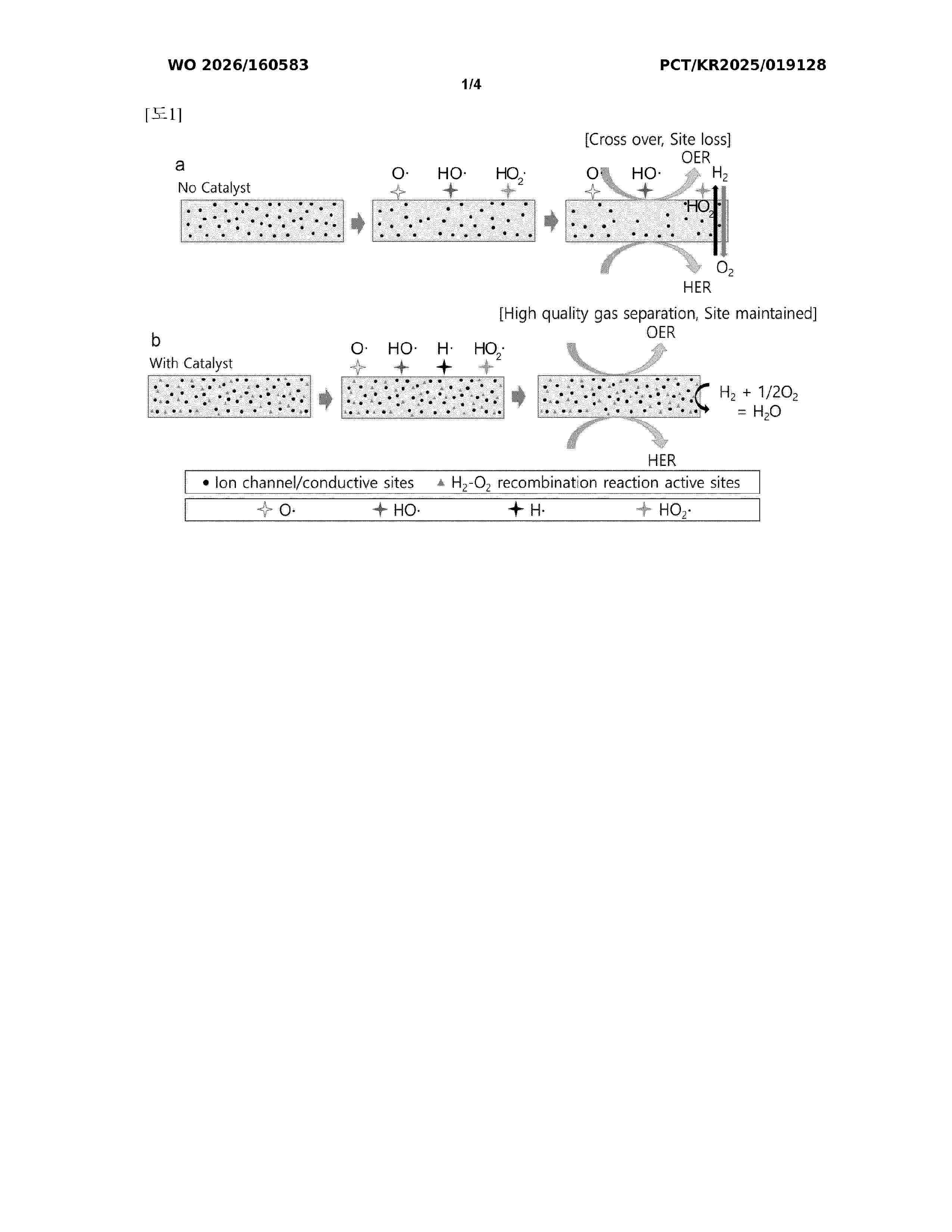
The water electrolysis separation membrane according to the present invention comprises a support mesh and a functional layer in which the support mesh is included, wherein the functional layer includes an ion-conducting material and a hydrogen-oxygen recombination catalyst.
Resumen de: US20260218396A1
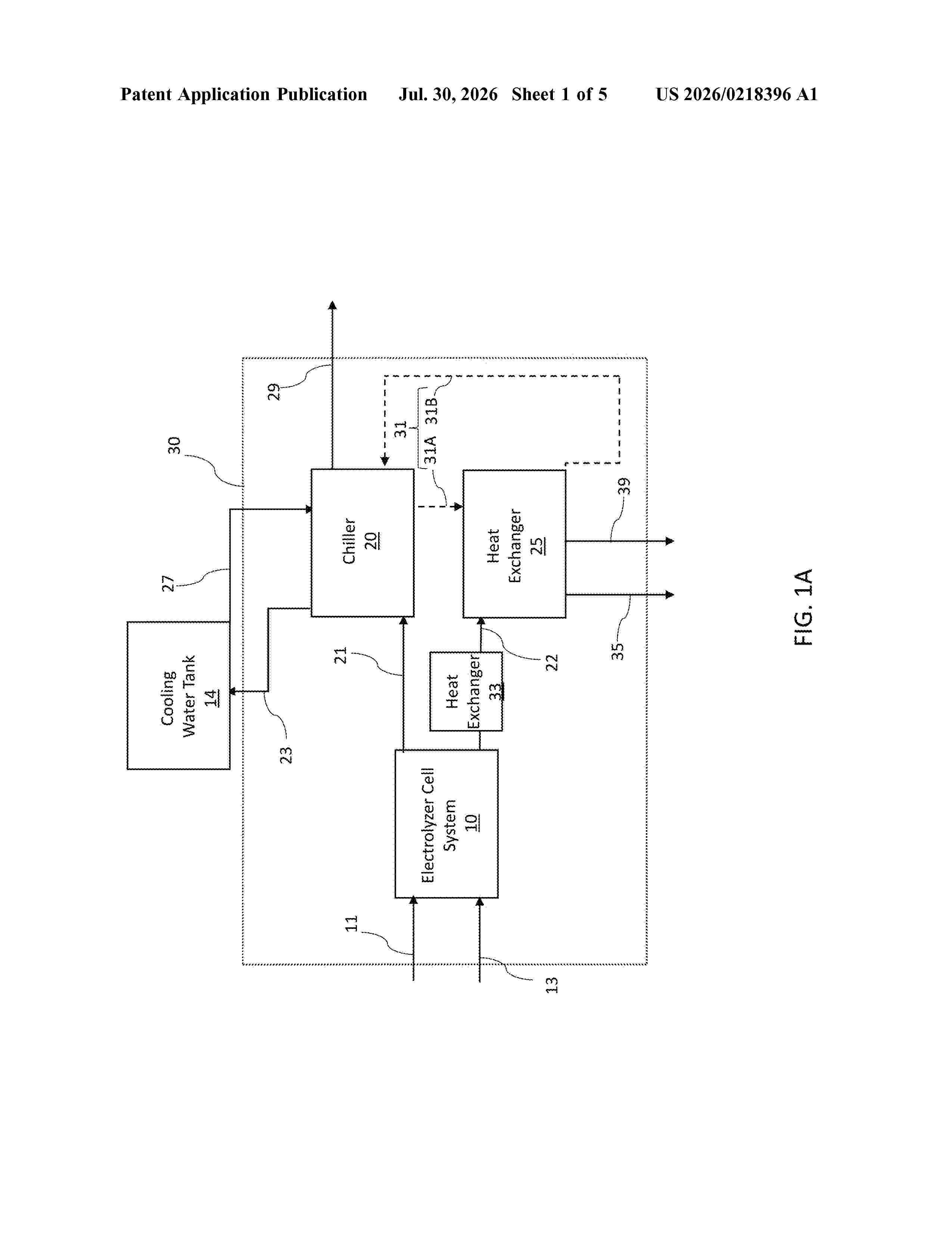
A system includes an electrolyzer cell system configured to receive a steam inlet stream and an air inlet stream and to generate a hydrogen containing product stream and an air exhaust stream, and an absorption chiller fluidly connected to the electrolyzer cell system. The absorption chiller is configured to receive the air exhaust stream and to cool the hydrogen containing product stream using heat from the air exhaust stream.
Resumen de: WO2026159932A1
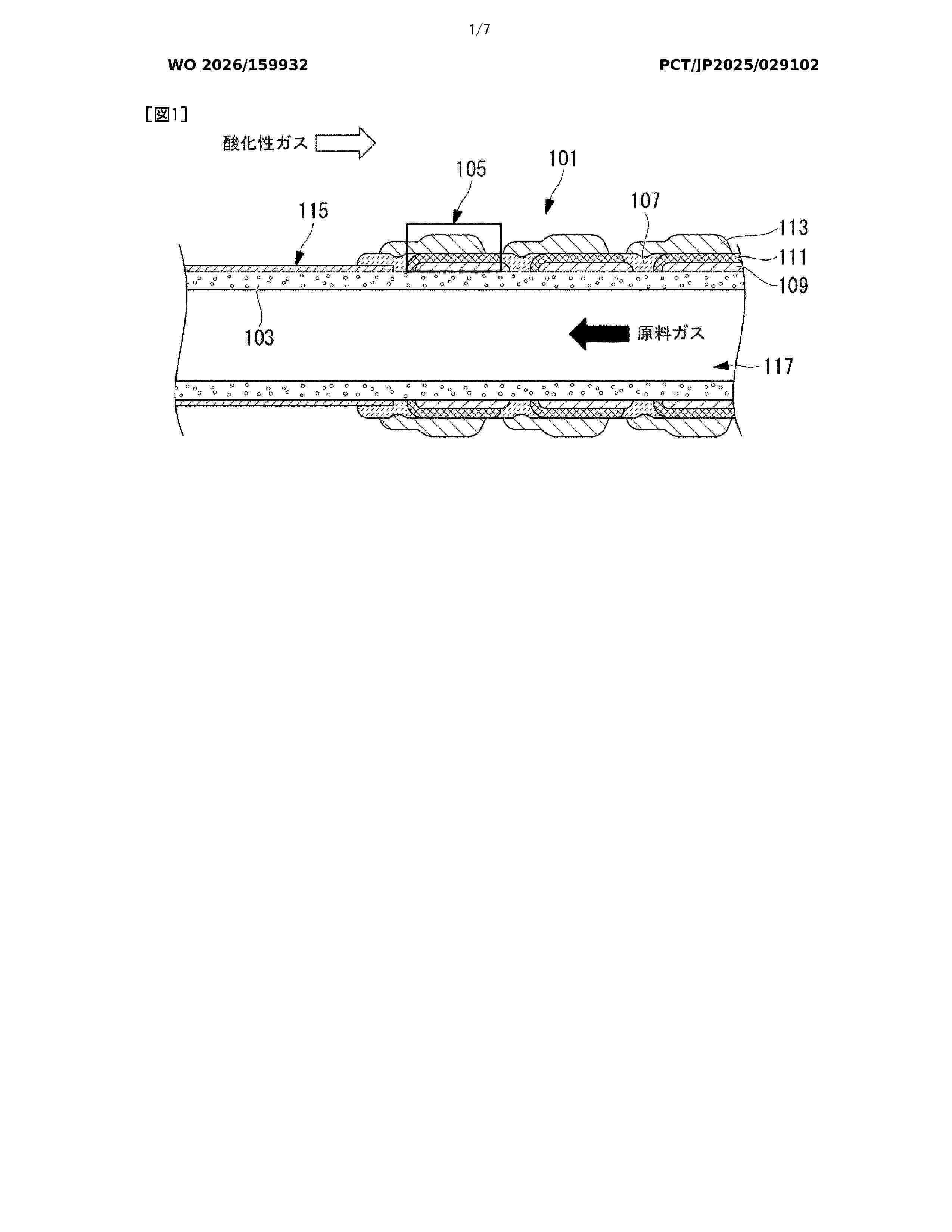
Provided are: an electrolysis cell stack in which a methanation reaction of a product gas that is generated at a hydrogen electrode by co-electrolysis can be suppressed even in cases where a methanation catalyst is contained in a flow passage through which the product gas flows; an electrolysis cell cartridge; an electrolysis cell module; and a method for suppressing methanation in an electrolysis cell stack. An electrolysis cell stack (101) according to the present disclosure comprises: an electrolysis cell (105) in which a hydrogen electrode, a solid electrolyte, and an oxygen electrode are stacked in sequence; a flow passage (117) through which a gas that is generated at the hydrogen electrode flows; and a hollow tube (140) which is disposed in the flow passage (117) so that the gas that is generated at the hydrogen electrode can flow therethrough. A member (103) that defines the outer contour of the flow passage (117) contains a methanation catalyst, and the hollow tube (140) does not contain a methanation catalyst.
Resumen de: WO2026159944A1
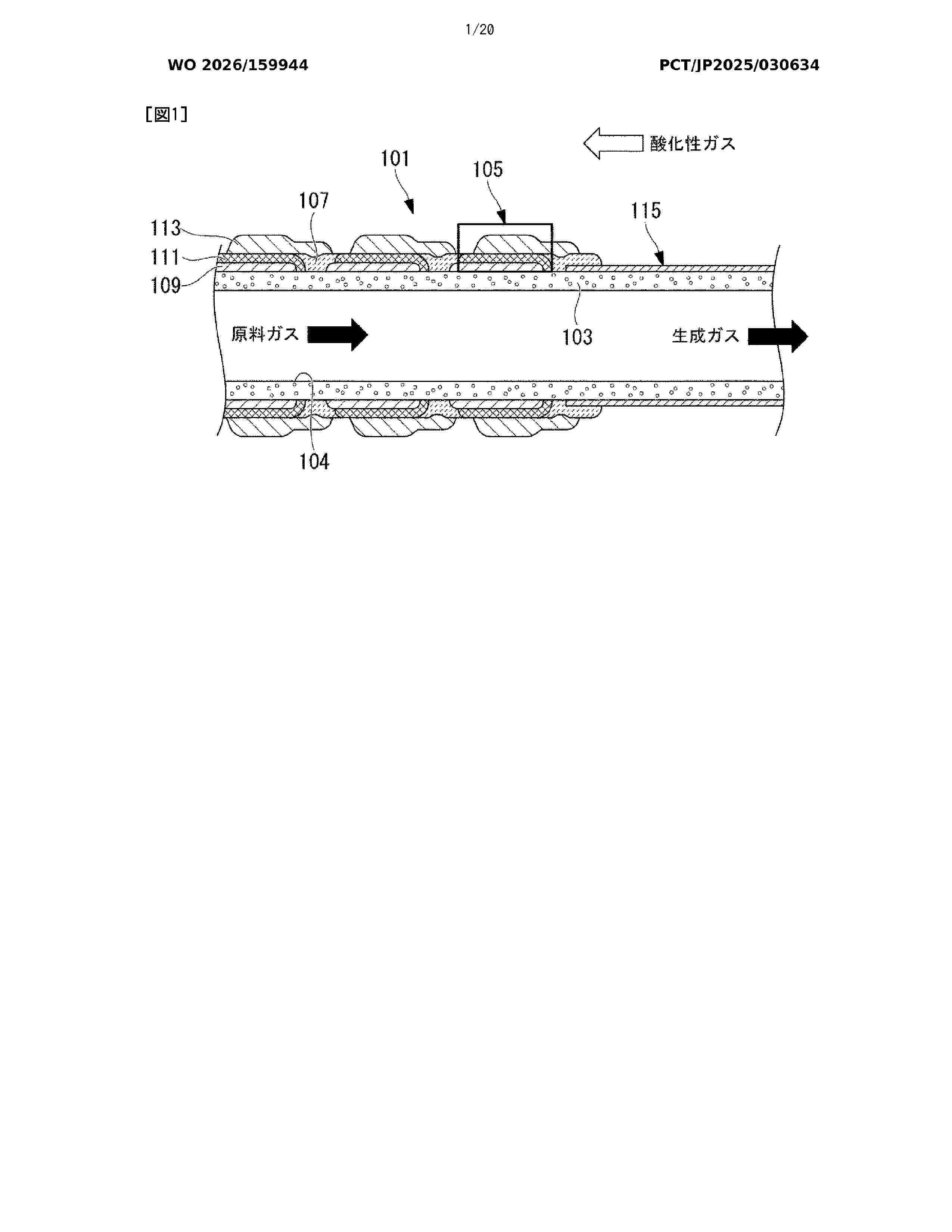
The purpose of the present invention is to suppress a methanation reaction of a product gas in a co-electrolysis system and a method for operating same. A co-electrolysis system (120) according to the present disclosure comprises an electrolysis cell stack (101) and a control unit (123). The electrolysis cell stack (101) includes: an electrolysis cell (105) in which a hydrogen electrode, a solid electrolyte, and an oxygen electrode are laminated in this order; a raw material gas flow path (124) through which a raw material gas containing H2O and CO2 supplied to the hydrogen electrode flows; and a product gas flow path (125) through which a product gas produced at the hydrogen electrode flows. The control unit (123) includes a methane concentration suppression unit (135) by which the concentration of methane in the off-gas discharged from the product gas flow path (125) is maintained below a threshold.
Resumen de: US20260216467A1
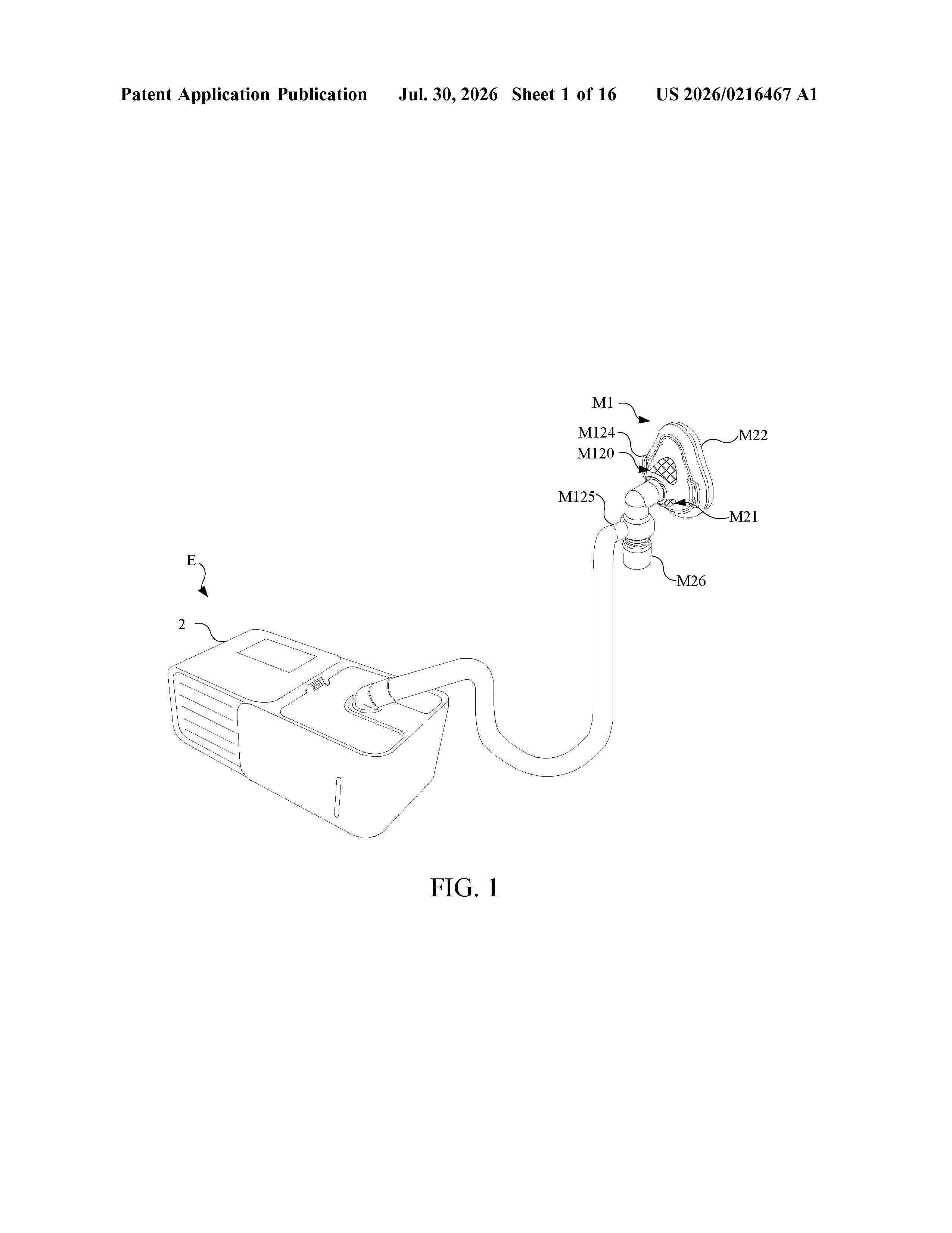
A breathing equipment for providing a positive pressure gas includes a gas channel, a hydrogen generating device, a pressurizing device, a mixing device, an atomizing device, and an output device. The hydrogen generating device, the pressurizing device, the mixing device, the atomizing device, and the output device are all coupled to the gas channel. The hydrogen generating device is configured to electrolyze water to generate a gas comprising hydrogen. The pressurizing device selectively accelerates an external gas to generate an accelerating gas. The mixing device is configured to mix the gas comprising hydrogen and the accelerating gas to generate a positive pressure gas. The atomizing device is configured to selectively generate an atomizing gas. The output device is configured to selectively output the gas comprising hydrogen, the positive pressure gas, the gas comprising hydrogen with the atomizing gas, or the positive pressure gas with the atomizing gas.
Resumen de: US20260217633A1
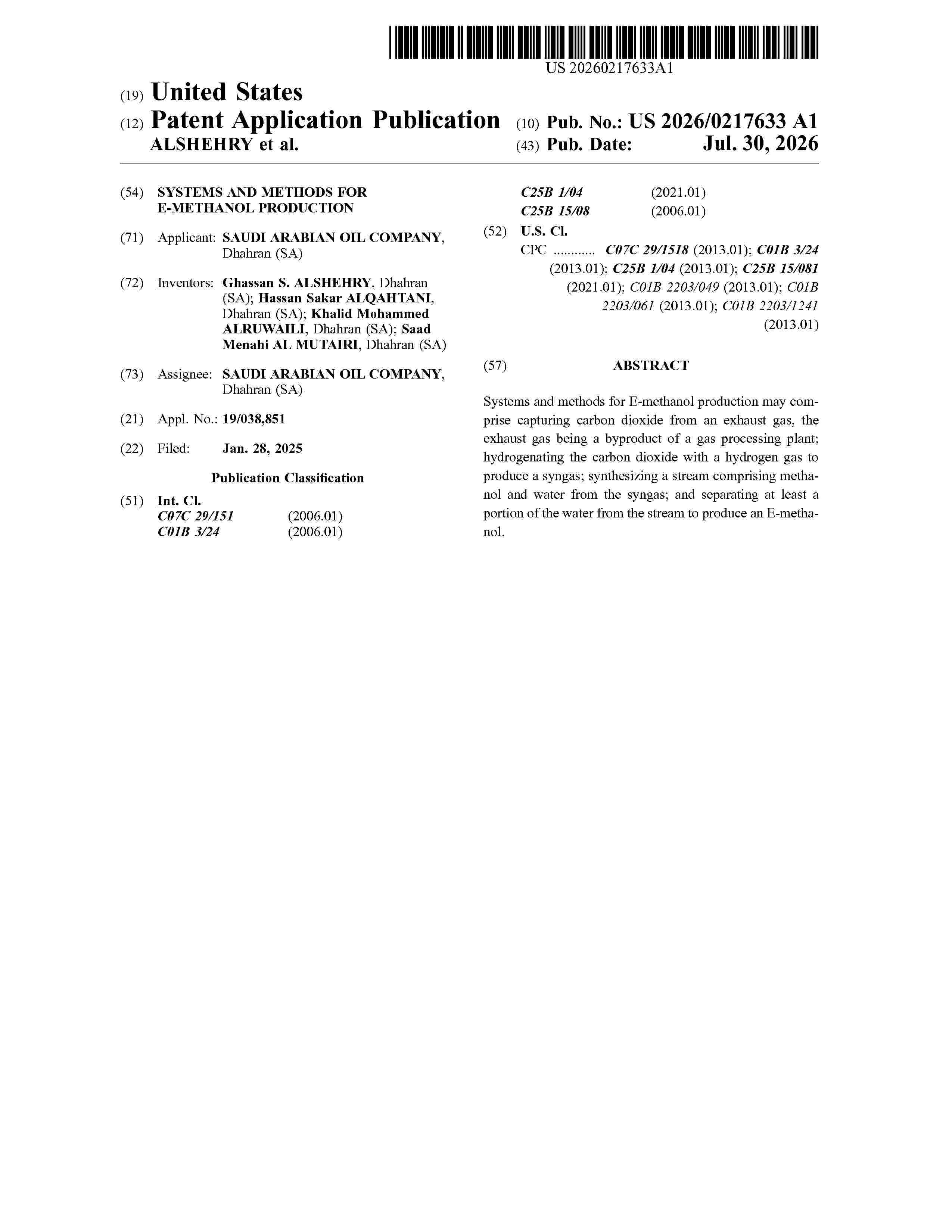
Systems and methods for E-methanol production may comprise capturing carbon dioxide from an exhaust gas, the exhaust gas being a byproduct of a gas processing plant; hydrogenating the carbon dioxide with a hydrogen gas to produce a syngas; synthesizing a stream comprising methanol and water from the syngas; and separating at least a portion of the water from the stream to produce an E-methanol.
Resumen de: US20260218400A1
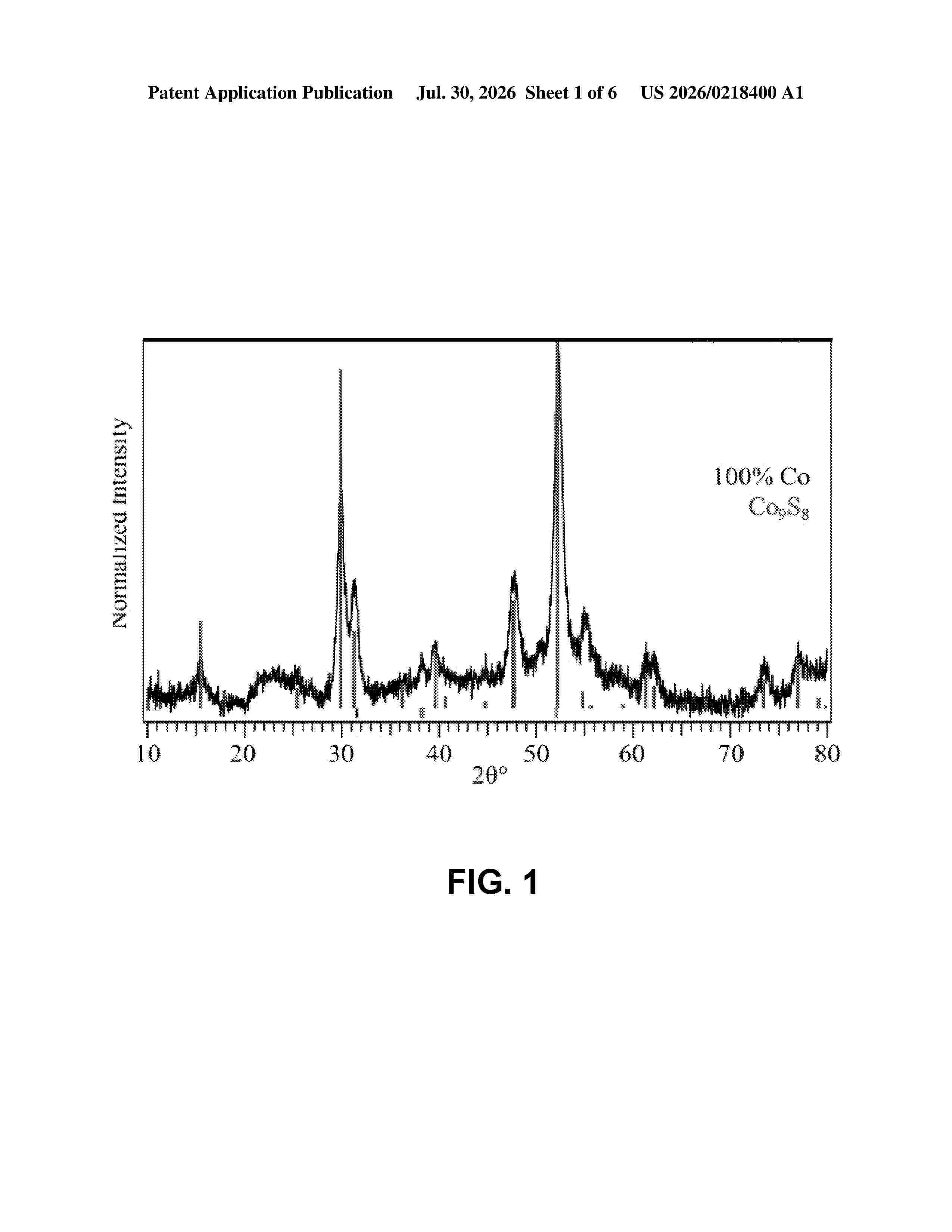
0000 For renewable energy technology to become ubiquitous, it is imperative to develop catalysts useful reactions such as, for example, efficient oxygen evolution reaction (OER) and hydrogen evolution (HER). In accordance with the purpose(s) of the present disclosure, described herein are compounds having one of the following the formula: ABX, ABCX, ABCDX, ABCDEX, ABCDEFX, or ABCDEFGX, wherein (1) A, B, C, D, E, F, and G are, independently, Cr, Mn, Fe, Co, Ni, Cu, and Zn, (2) A, B, C, D, E, F, and G are not the same element, and (3) X is absent or X is C, O, S, P, N, Te, Se, or As. The compounds described herein possess unique electrochemical properties.
Resumen de: US20260217634A1
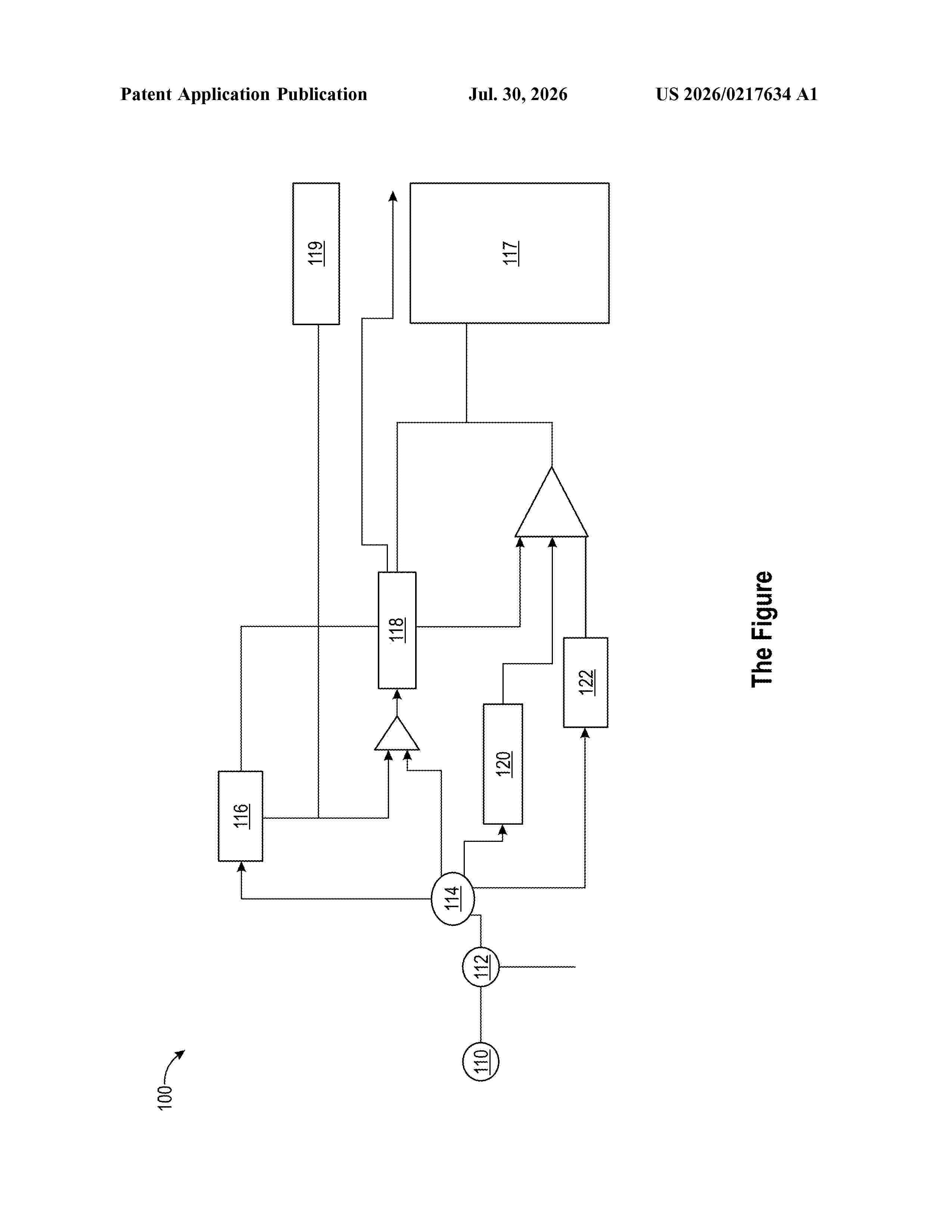
A method for processing flowback may comprise: providing flowback fluid comprising produced water, methane, hydrogen sulfide, and carbon dioxide; separating the flowback fluid into produced water, methane, hydrogen sulfide, carbon dioxide streams; producing a hydrogen stream and a carbon dioxide stream from the methane stream; producing a hydrogen stream from the hydrogen sulfide stream; and producing a hydrogen stream from the produced water stream. A flowback fluid processing system may comprise: a flowback fluid separator; a water splitting unit; a methane conversion unit; a hydrogen sulfide converter; a carbon dioxide reducing unit; and a synthesis unit.
Nº publicación: DE102025103028A1 30/07/2026
Solicitante:
THE YELLOW SIC HOLDING GMBH [DE]
The Yellow SiC Holding GmbH
Resumen de: DE102025103028A1
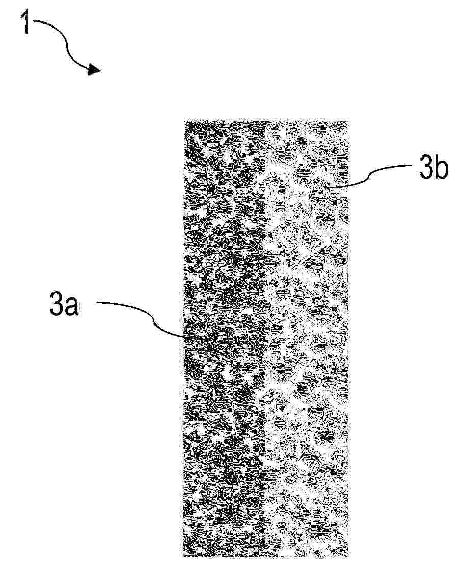
Es wird ein Verfahren zur Herstellung einer SiC-Elektrode 1 angegeben. Das Verfahren weist auf: Bereitstellen eines SiC-Pulvers und Sintern des SiC-Pulvers zu einem SiC-Sinterkörper.Des Weiteren wird eine SiC-Elektrode 1 angegeben, die ein gesintertes Elektrodenmaterial 3a,3b aufweist.
 BOPI
BOPI
 Sede Electrónica