Si deseas distinguir tus productos, servicios o ambos de los de otra empresa, es posible que necesites una marca o nombre comercial. Descubre qué son, en qué consiste su procedimiento de registro y qué implica.

Información sobre los plazos de presentación de solicitudes de transformación de marcas de la Unión Europea en marca nacional española. Más información


Si tienes un nuevo dispositivo, producto o procedimiento que resuelva un problema técnico o tenga una ventaja práctica, existen distintas formas de protegerlo en España y en otros países. Descubre cómo hacerlo.

¿Tu innovación reside en la estética, la ornamentación o la apariencia de tu producto? Protégela mediante un diseño industrial. Descubre qué derechos confiere el registro y cómo realizar la tramitación.

Las indicaciones geográficas protegen el nombre de un producto originario de una zona geográfica, a la cual le debe una determinada calidad, reputación u otra característica. Descubre qué son, en qué consiste su procedimiento de registro y qué beneficios conceden.

Las patentes publicadas en todo el mundo son una valiosa fuente de información científica, técnica y comercial.

Si eres emprendedor/a o una empresa y quieres potenciar y mejorar la rentabilidad de tu negocio protegiendo de forma adecuada los activos intangibles de tu organización, en este espacio encontrarás lo necesario.


 117
resultados
117
resultados
 Última actualización
08/05/2026 [08:05:00]
Última actualización
08/05/2026 [08:05:00]


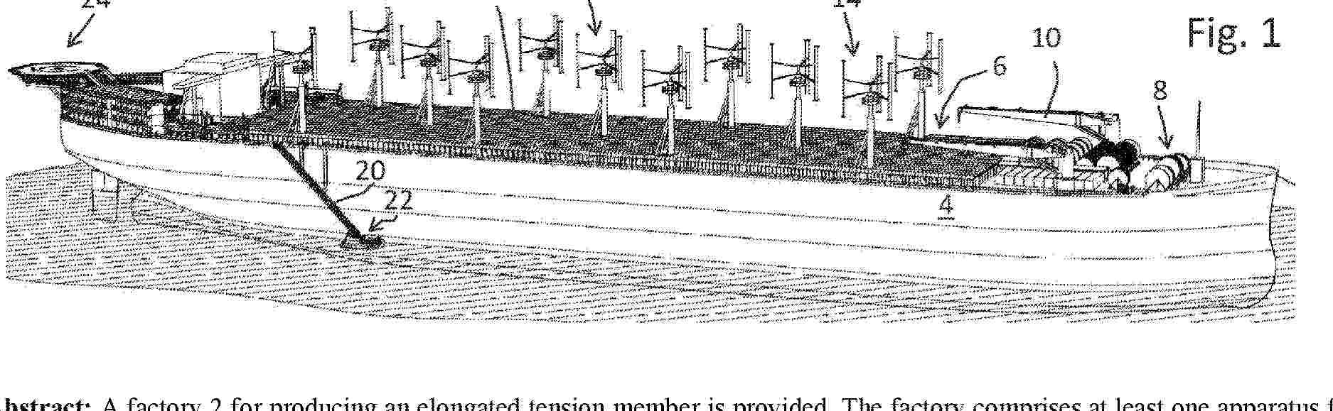
Resumen de: AU2024382071A1
A factory 2 for producing an elongated tension member is provided. The factory comprises at least one apparatus for producing the elongated tension member. The at least one apparatus comprises: a feeder, a processing device and at least one end fitting device. The feeder is arranged to provide input material. The input material comprises: at least one load bearing yarn and/or at least one load bearing wire and/or load bearing fibres. The processing device is arranged to wind and/or twist and/or bundle the input material provided by the feeder. The at least one end fitting device is arranged to provide the elongated tension member with a proximal end fitting and a distal end fitting. The factory further comprises a buoyant body 4 arranged to support said at least one apparatus for producing the elongated tension member.

Resumen de: EP4737711A1
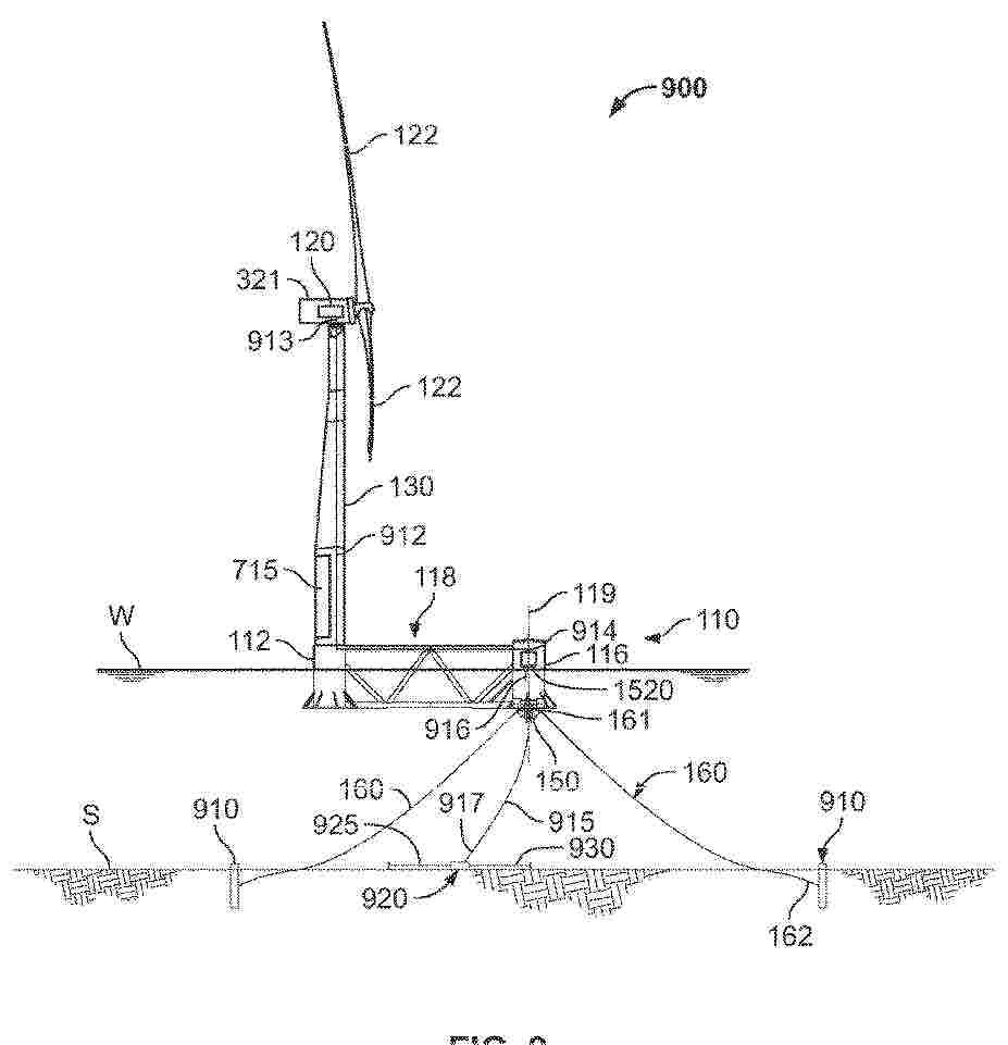
0001 The present application relates to a wind turbine foundation, a wind turbine, and a control method. The wind turbine foundation includes: a floating body, comprising a main column, a plurality of auxiliary columns, and connecting bodies, the main column being used for connecting to a tower, the bottom wall of each auxiliary column being provided with a stabilization device, the stabilization device comprising a drive assembly, a first impeller, and a base connected to the auxiliary column, the base having an inner cavity, and a first opening and a second opening communicating with the inner cavity, the first opening and the second opening having a height difference in a first direction, the first opening, the inner cavity, and the second opening forming a flow channel for seawater, the first impeller being disposed in the inner cavity, the drive assembly driving the first impeller to rotate and causing the seawater to flow within the flow channel, so as to adjust a tilt angle between the floating body as a whole and a reference plane. The present application has a simple structure and relatively low cost.
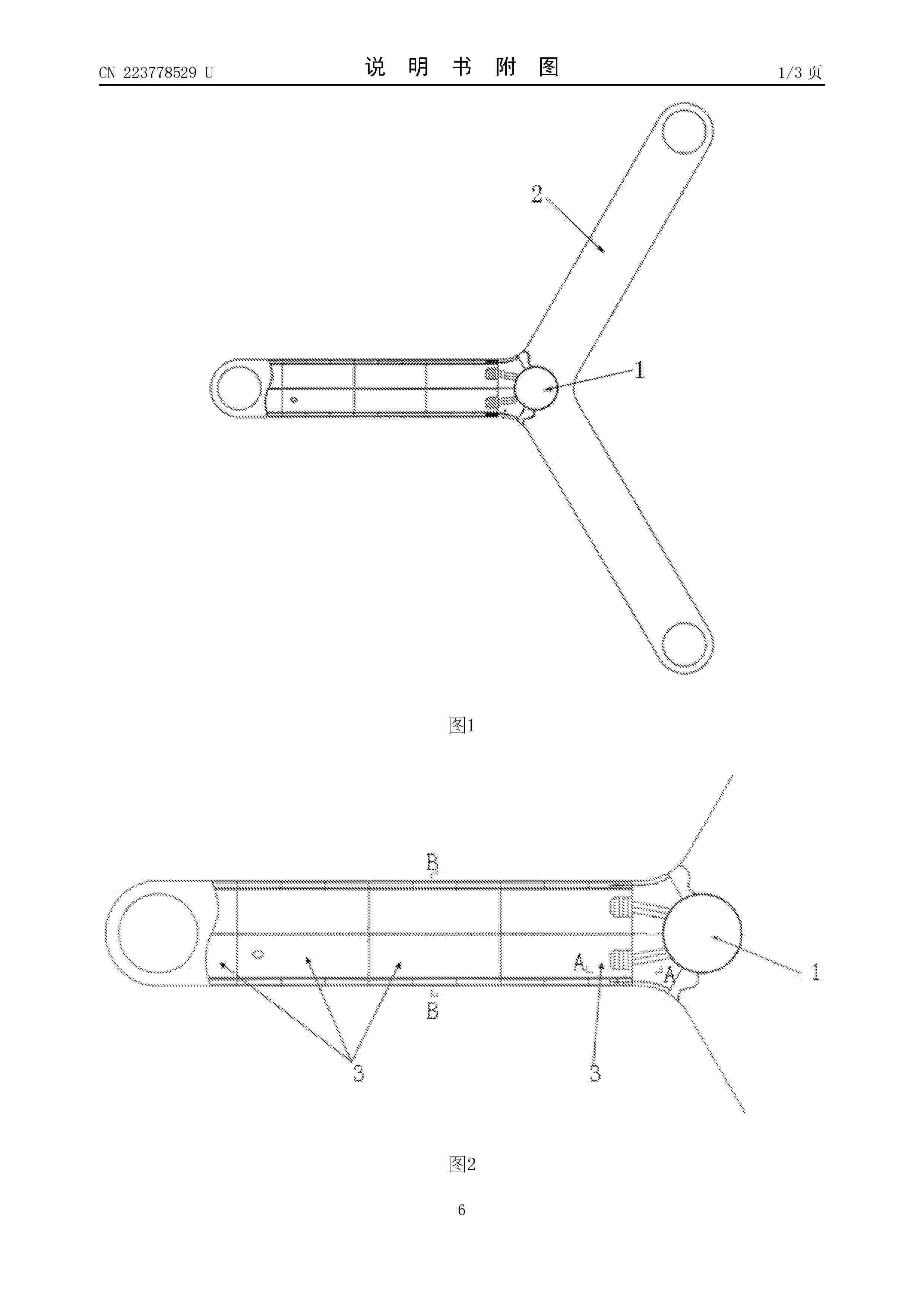
Resumen de: EP4737298A1
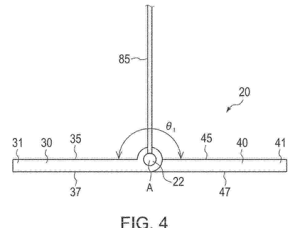
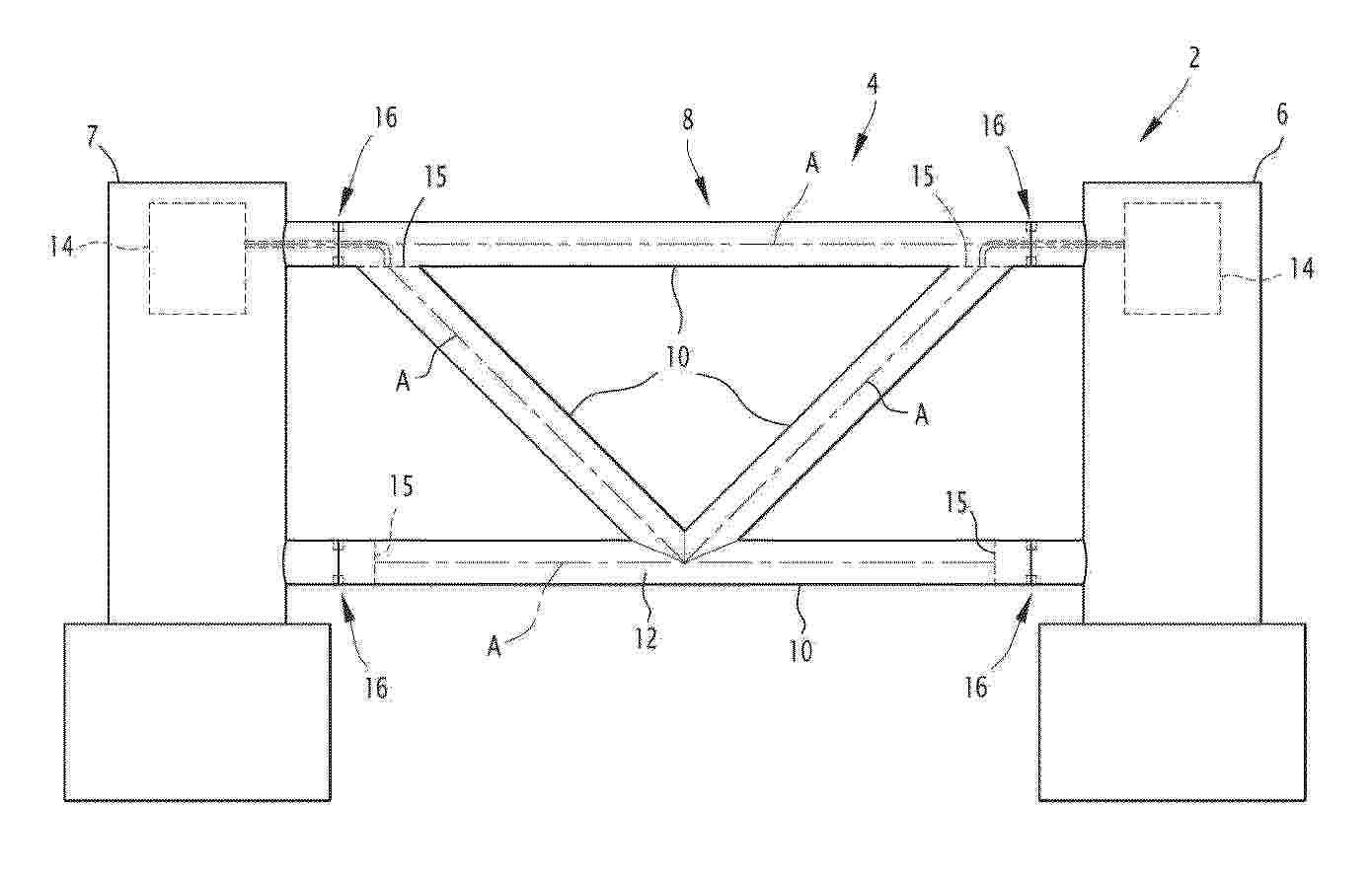
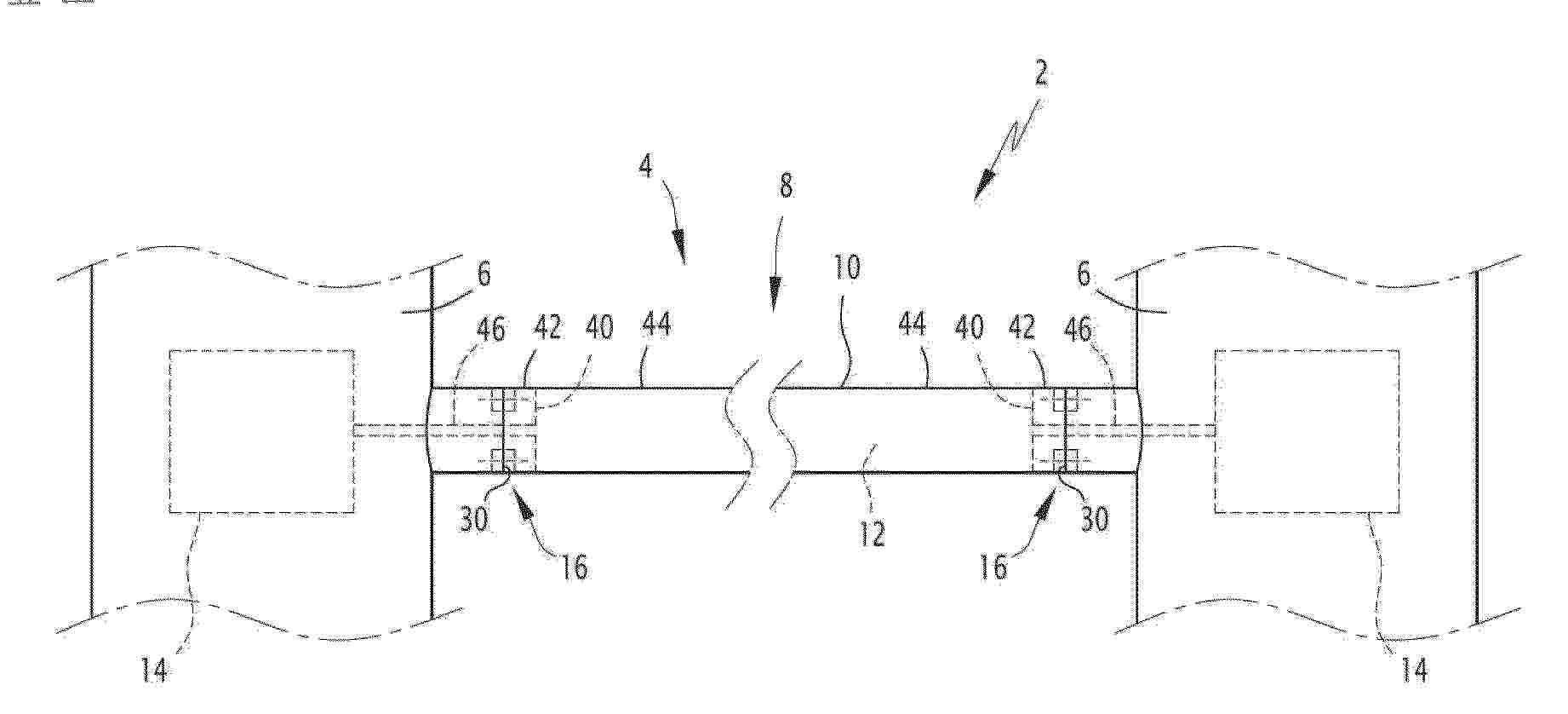
0001 An anchor device (20) includes: a shaft member (22) extending along a central axis (A) and receiving attachment of a tension member (85); and a first plate member (30) and a second plate member (40) configured to be rotatable relative to each other about the central axis (A), in which the first plate member (30) includes a first back end portion (31) farthest from the central axis (A) in a direction in which the first plate member (30) extends and a direction orthogonal to the central axis (A), the second plate member (40) includes a second back end portion (41) farthest from the central axis (A) in a direction in which the second plate member (40) extends and a direction orthogonal to the central axis (A), and the anchor device (20) is configured to be able to change from a folded state in which the first back end portion (31) and the second back end portion (41) are close to each other to an unfolded state in which the first back end portion (31) and the second back end portion (41) are far from each other.
Resumen de: EP4737714A1
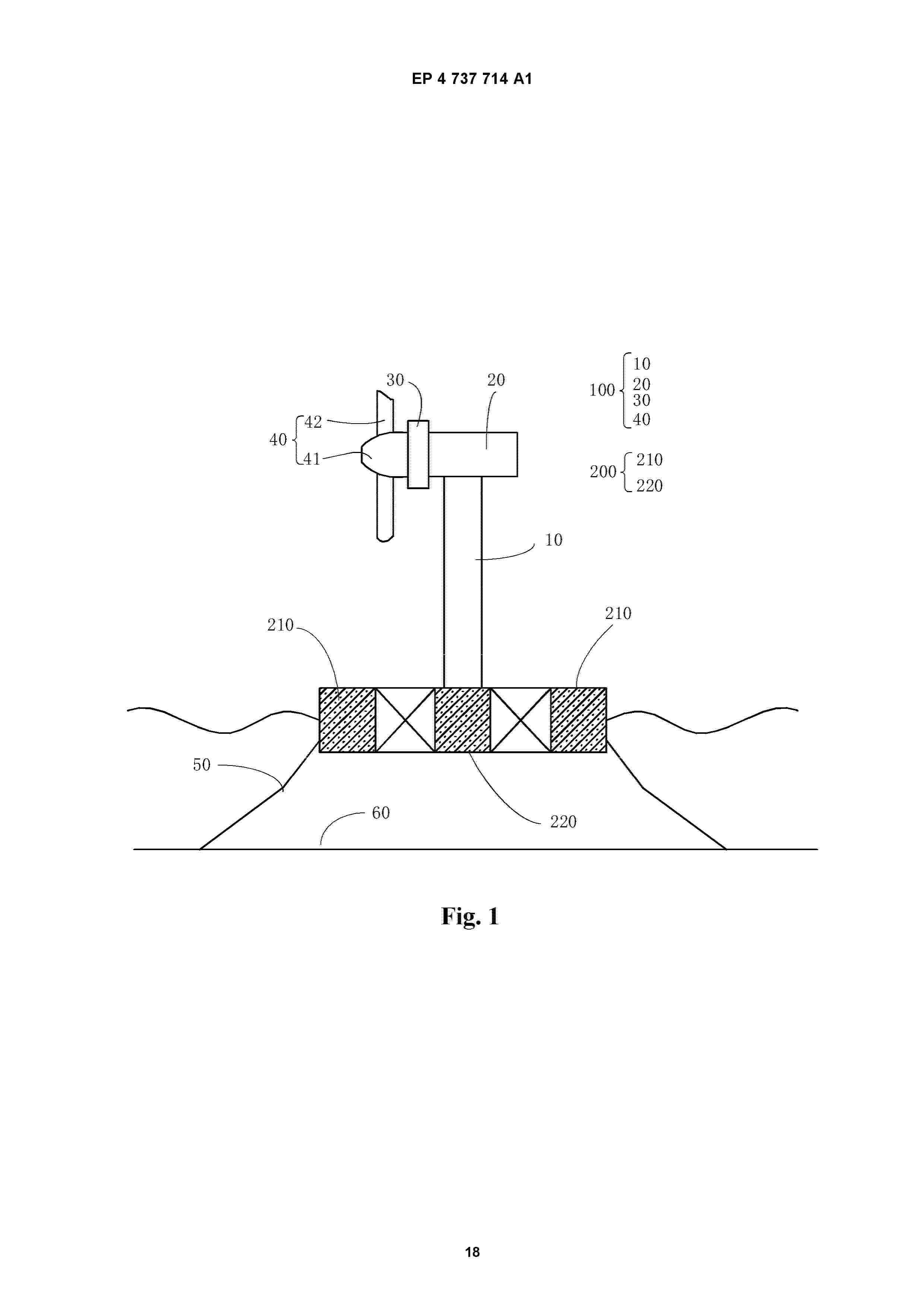
0001 The present application relates to a floating-type wind turbine floating body, a wind turbine generator system and a control method. The floating-type wind turbine floating body includes: a main column, configured to support a tower; a plurality of first connecting bodies, wherein the plurality of first connecting bodies are arranged at intervals in a circumferential direction of the main column and are connected to the main column respectively; a plurality of auxiliary columns, wherein the plurality of auxiliary columns are distributed at intervals in the circumferential direction, and one end of each of the first connecting bodies facing away from the main column is connected to a corresponding auxiliary column of the auxiliary columns; wherein each of the auxiliary columns has a first static chamber and a first dynamic chamber that are independently arranged, a first medium is enclosed within the first static chamber, each of the auxiliary columns is provided with a first opening connected to the first dynamic chamber and a first control valve, and the first control valve controls opening and closing of the first opening to adjust a volume of the seawater entering the first dynamic chamber. According to the floating-type wind turbine floating body, wind turbine generator system and control method provided in the embodiments of the present application, the floating-type wind turbine floating body has a fast response speed and a good stability effect.
Resumen de: EP4737713A1
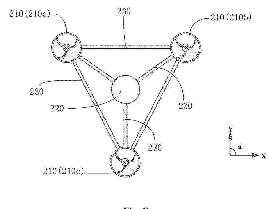
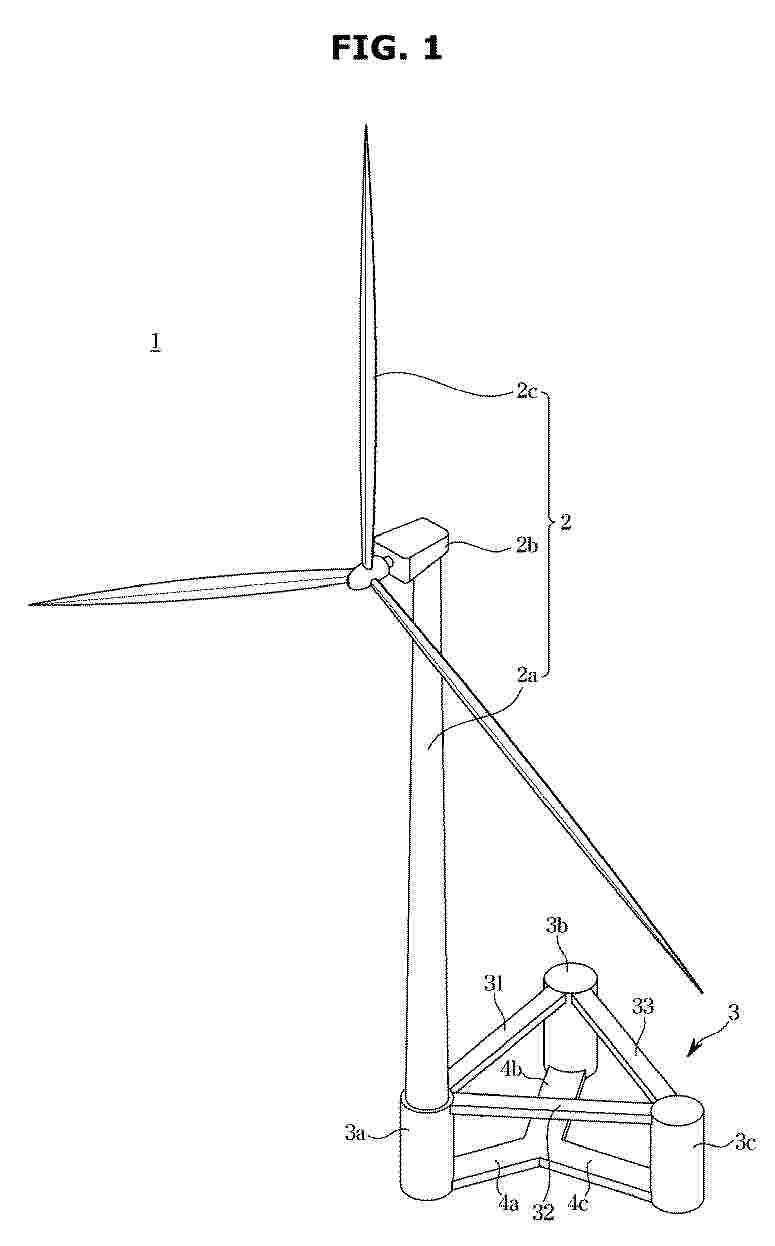
The present application relates to a wind turbine foundation, a wind turbine generator system and a control method. The wind turbine foundation is capable of being arranged in seawater and configured to support a tower, wherein the wind turbine foundation includes: floating bodies, wherein a number of the floating bodies is n, the floating bodies are arranged at intervals from each other, and lines connecting centers of the floating bodies form a polygon as a whole, where n≥3; connecting bodies, wherein a corresponding one of the connecting bodies is connected between every two adjacent floating bodies; wherein each of the floating bodies has a static chamber and a dynamic chamber that are independently arranged, a first medium is enclosed within the static chamber, each of the floating bodies is provided with a first opening connected to the dynamic chamber and a first control valve, and the first control valve controls opening and closing of the first opening to adjust a volume of the seawater entering the dynamic chamber. According to the wind turbine foundation, wind turbine generator system and control method provided in the embodiments of the present application, the wind turbine foundation has a fast response speed and a good stability effect.
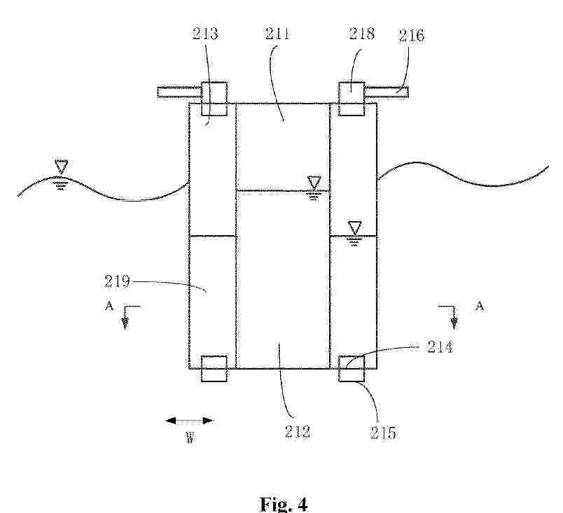
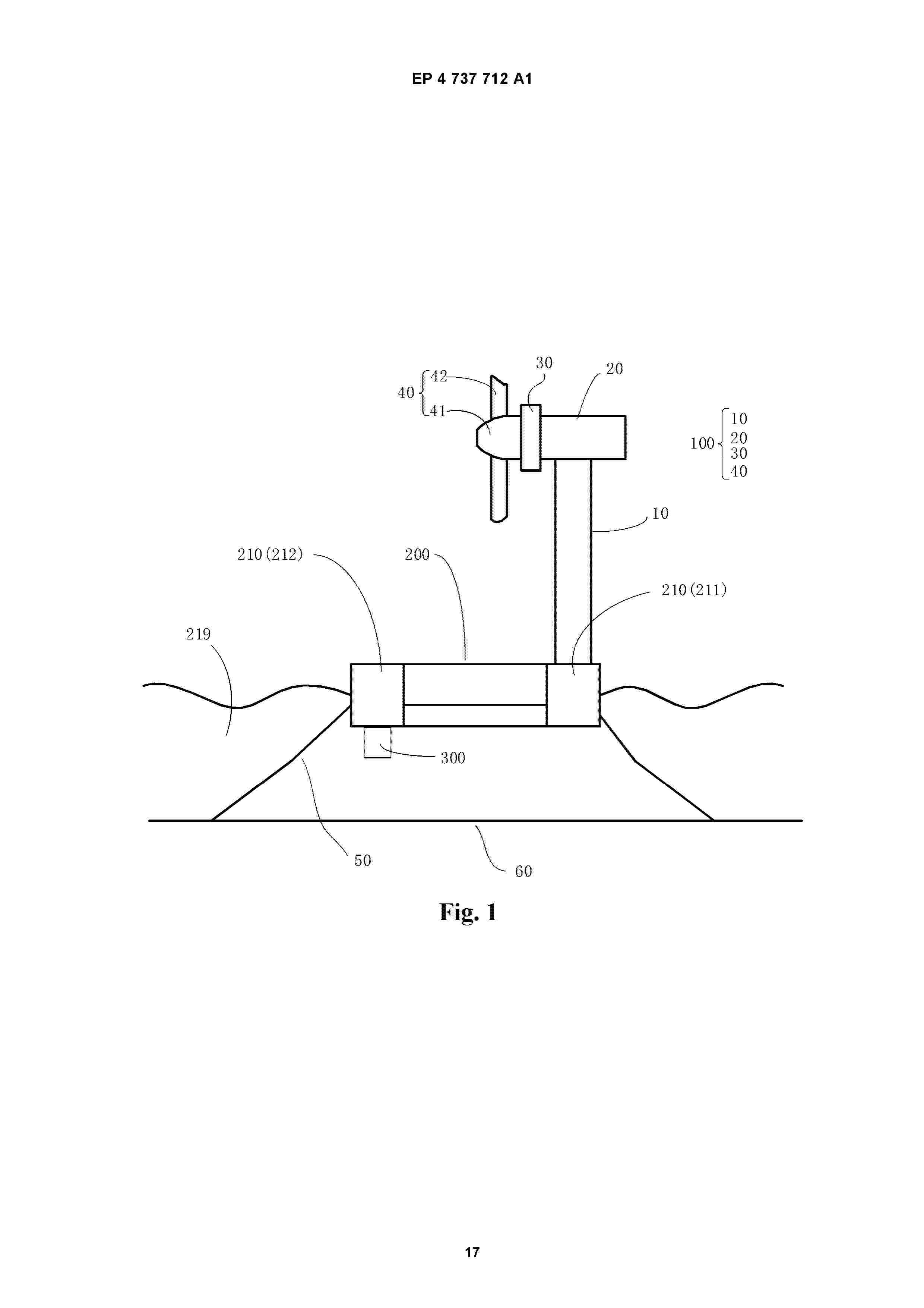
Resumen de: EP4737712A1
0001 The present application relates to a floating support foundation, a wind turbine, and a control method. The floating support foundation includes: a floating main body including n floating columns spaced apart around a first axis and connecting bodies connecting every adjacent two of the floating columns, n≥3, the n floating columns including one first floating column and n-1 second floating columns, and the first floating column being used for supporting the tower; stabilization devices, each of the second floating columns being connected to a respective one of the stabilization devices, the stabilization device including a drive assembly, a first impeller, and a base connected to the second floating column, the base having an inner cavity, and a first opening and a second opening communicating with the inner cavity, the first opening, the inner cavity, and the second opening forming a flow channel for the seawater, the first impeller being disposed in the inner cavity, the drive assembly driving the first impeller to rotate and causing the seawater to flow within the flow channel, so as to adjust the second floating column connected to the stabilization device to float upward or sink downward. The present application has a simple structure and relatively low cost.
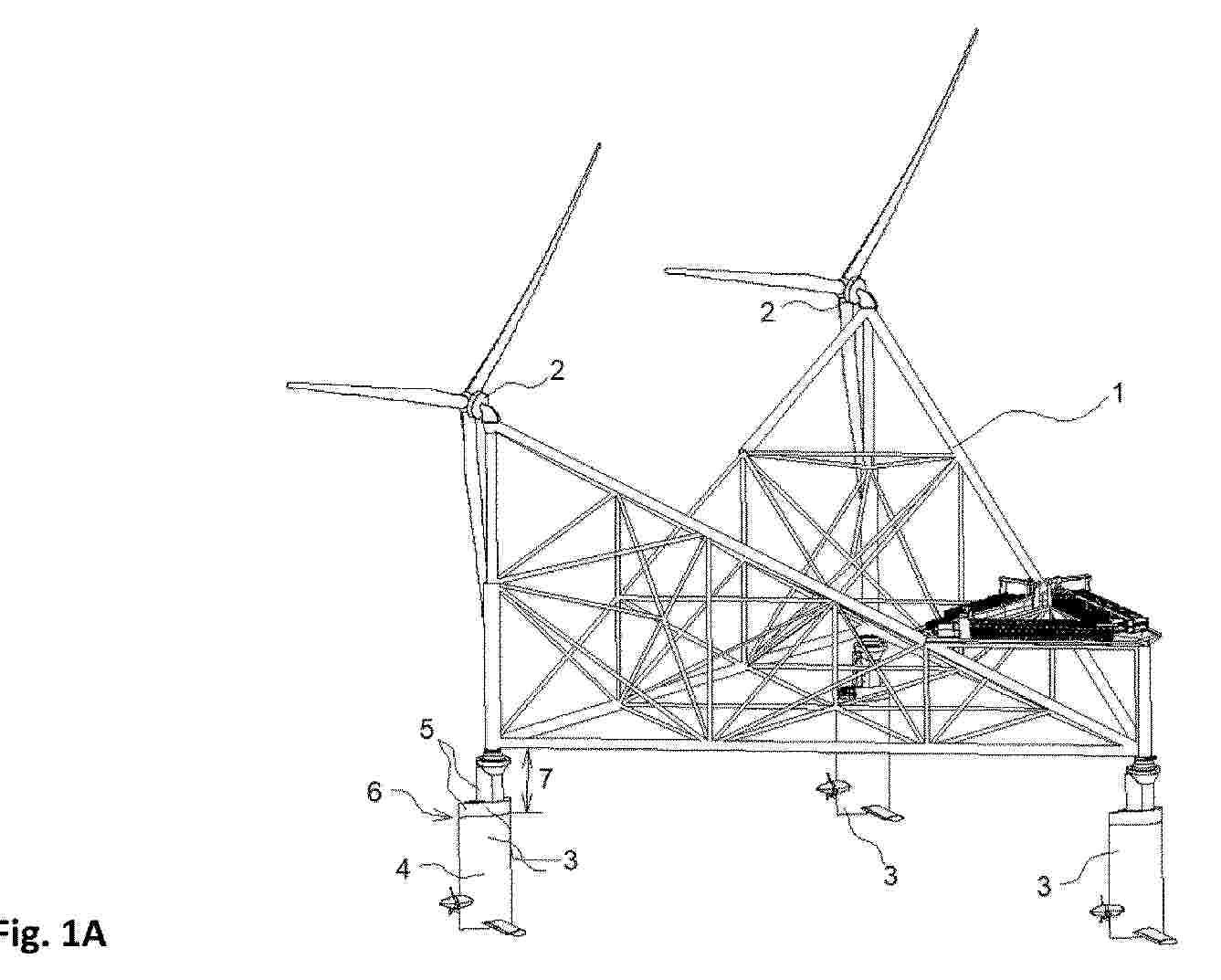
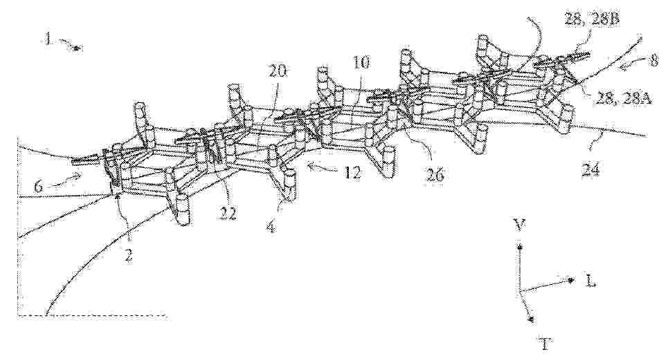
Resumen de: WO2025003138A1
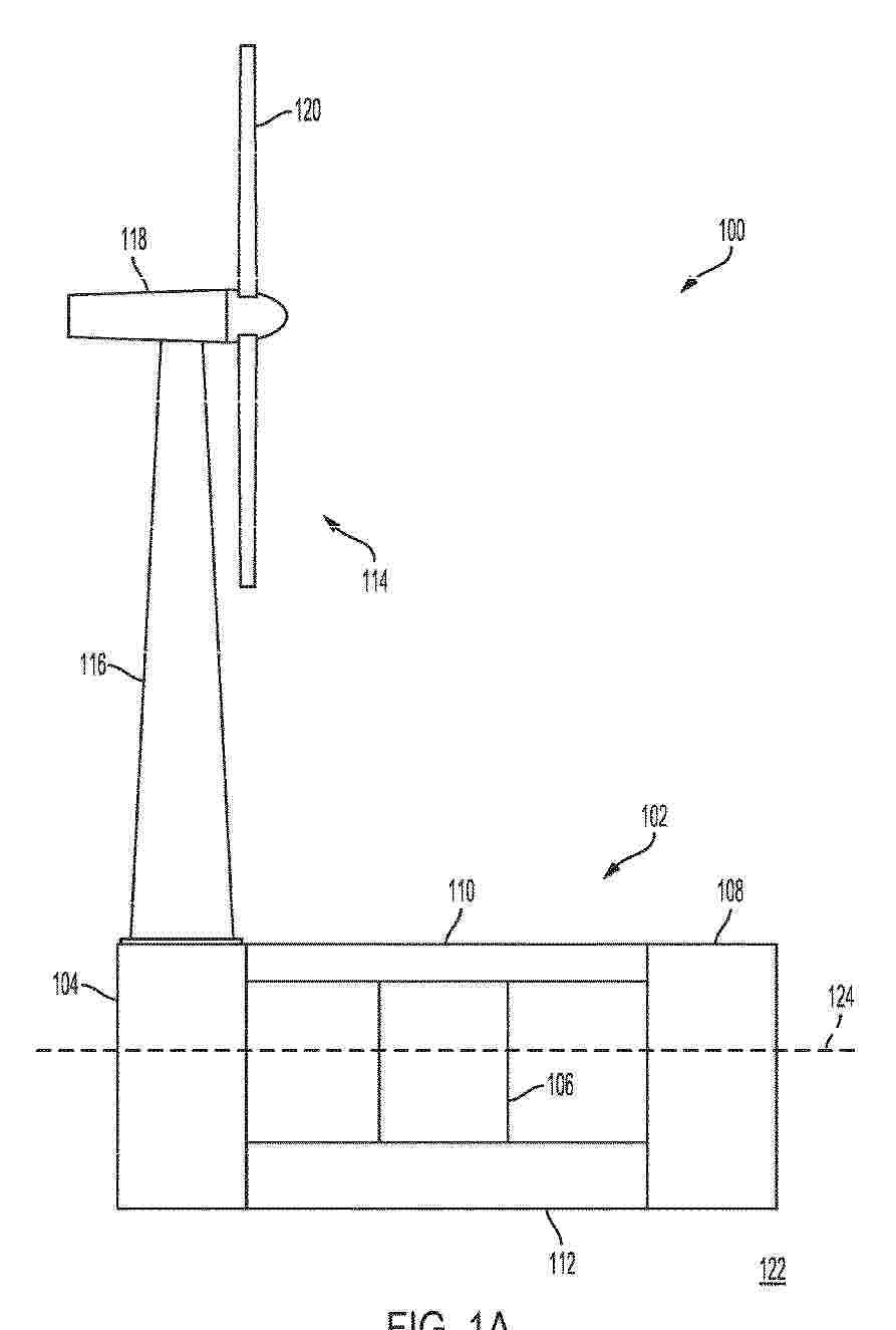
The invention describes a barge for assembly of a floating support structure (1) comprising a lower buoyancy section (2) with a lower buoyancy volume VL and a working deck (3) comprising support elements (4) for receiving parts of the floating support structure to be assembled. The barge further comprises a ballasting system (7) for lowering and elevating the barge (1). The barge is characterized by a divisional section (6) holding the lower buoyancy section (2) and the working deck (3) in a vertical distance from each other and having a divisional buoyancy volume VD considerably smaller than lower buoyancy volume VL, such that the ballasting system, by pumping a quantity of water equal to VD in or out, is able to move the barge (1) between a lower position with a bottom side of the working deck (3) in the waterline, and an upper position with the top side of the lower buoyancy section (2) in the waterline.
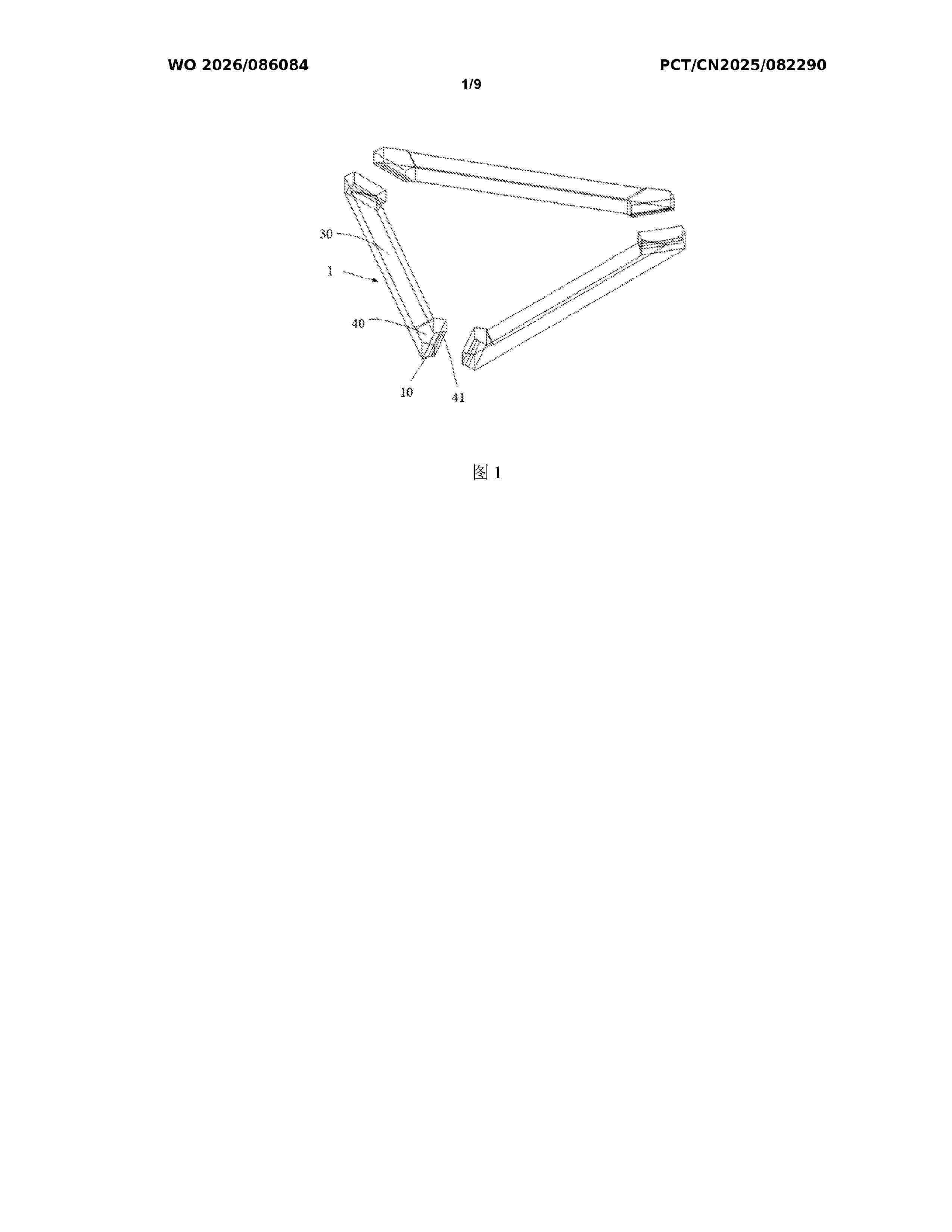
Resumen de: WO2026086084A1
The present application relates to a floating wind power foundation assembled on water, the floating wind power foundation comprising: a plurality of independent floating bodies (1), the plurality of floating bodies (1) being connected to each other to form a foundation floating body having a polygonal structure, end portions of each floating body (1) being provided with cut slanted bottom surfaces, cut slanted bottom surfaces of two adjacent floating bodies (1) being connected to form a through opening, and a welding region at the joint being located above the through opening; and a plurality of columns (2), mounted on the foundation floating body.
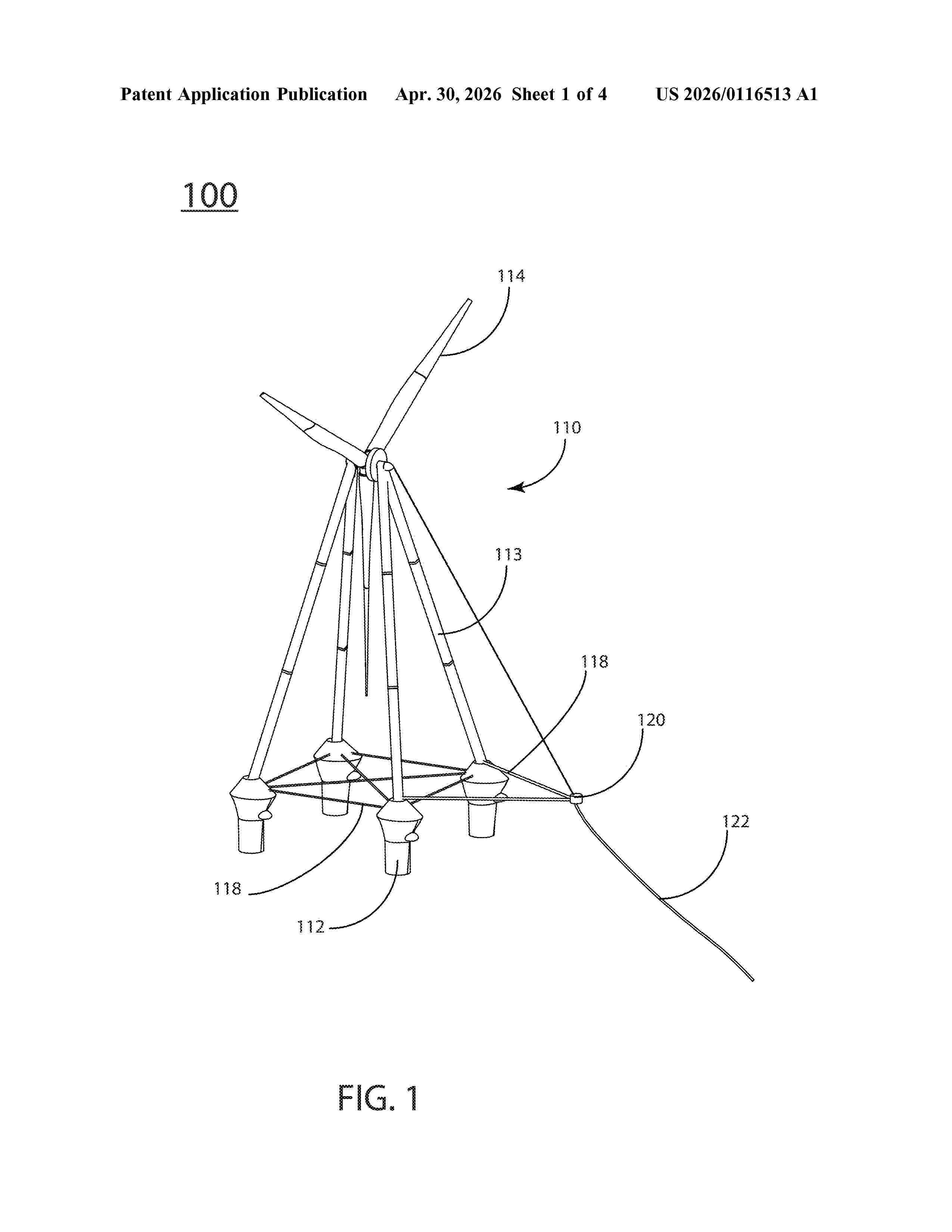
Resumen de: US20260116513A1
A floating wind turbine is supported by floats that are made up of a bow form having a bulbous form protrusion and a lower cylindrical portion. Ballast is controlled to move the water line below the bow during operation and above the bow and bulbous form during towing.
Resumen de: EP4733186A1
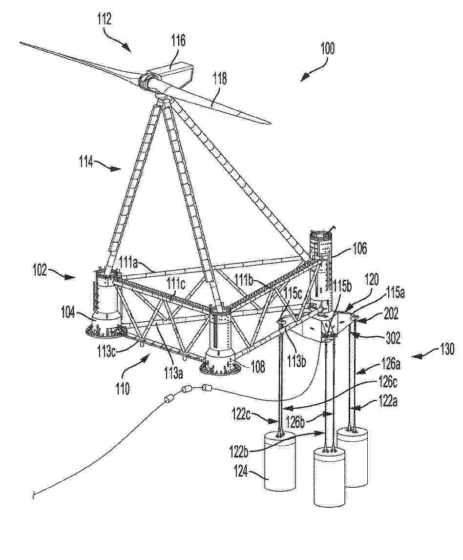
This disclosure relates to an unmoored floating wind turbine system comprising a connecting structure that bears one or more wind turbines, and at least three hulls or topological concentrations of buoyancy-force, wherein the connecting structure is configured to transmit moments and forces between the at least three hulls and the one or more wind turbines, and at least two lifting surfaces, such as foils and/or keels and/or fins and/or hulls, wherein the at least two lifting surfaces have separately controllable orientations relative to the structure for controlling a course direction of the unmoored floating wind turbine system and for controlling a heading of the connecting structure independently from the course direction.
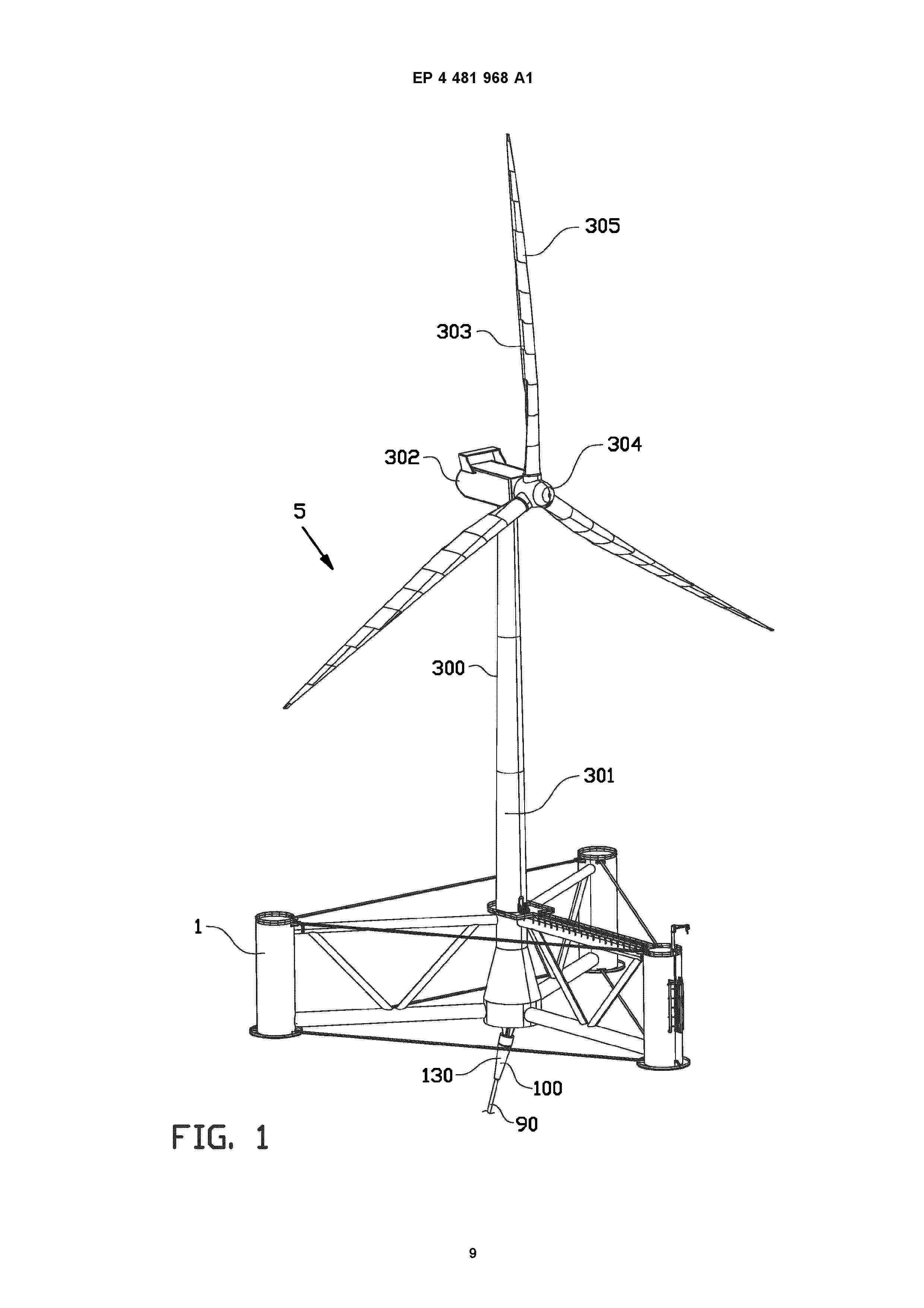
Resumen de: EP4481968A1
The invention relates to a cable connector system for connecting an electric power cable in a cable connector channel that debouches at a bottom of a floating marine platform, wherein the cable connector system comprises an insert connector for insertion into the cable connector channel, a cable hang-off to be fixated to the electric power cable, multiple pulling ropes that extend aside each other between the insert connector and the cable hang-off, and a cable protector on the cable hang-off, wherein the insert connector, the pulling ropes, the cable hang-off and the cable protector define subsequent cable passage sections of an internal cable passage for the electric power cable.
Resumen de: WO2025006514A1
A barge-type wind turbine platform that is capable of floating on a body of water and supporting a wind turbine includes a keystone. The keystone includes a steel tube concentrically mounted within the keystone, and a plurality of radially extending diaphragms that extend vertically between a lower wall of the keystone and an upper wall of the keystone, and extend radially between the steel tube and side walls of the keystone. A plurality of bottom beams are connected to the keystone and extend radially outwardly thereof, and the combined keystone and bottom beams define a foundation. A wind turbine tower is mounted to the keystone.
Resumen de: AU2024354901A1
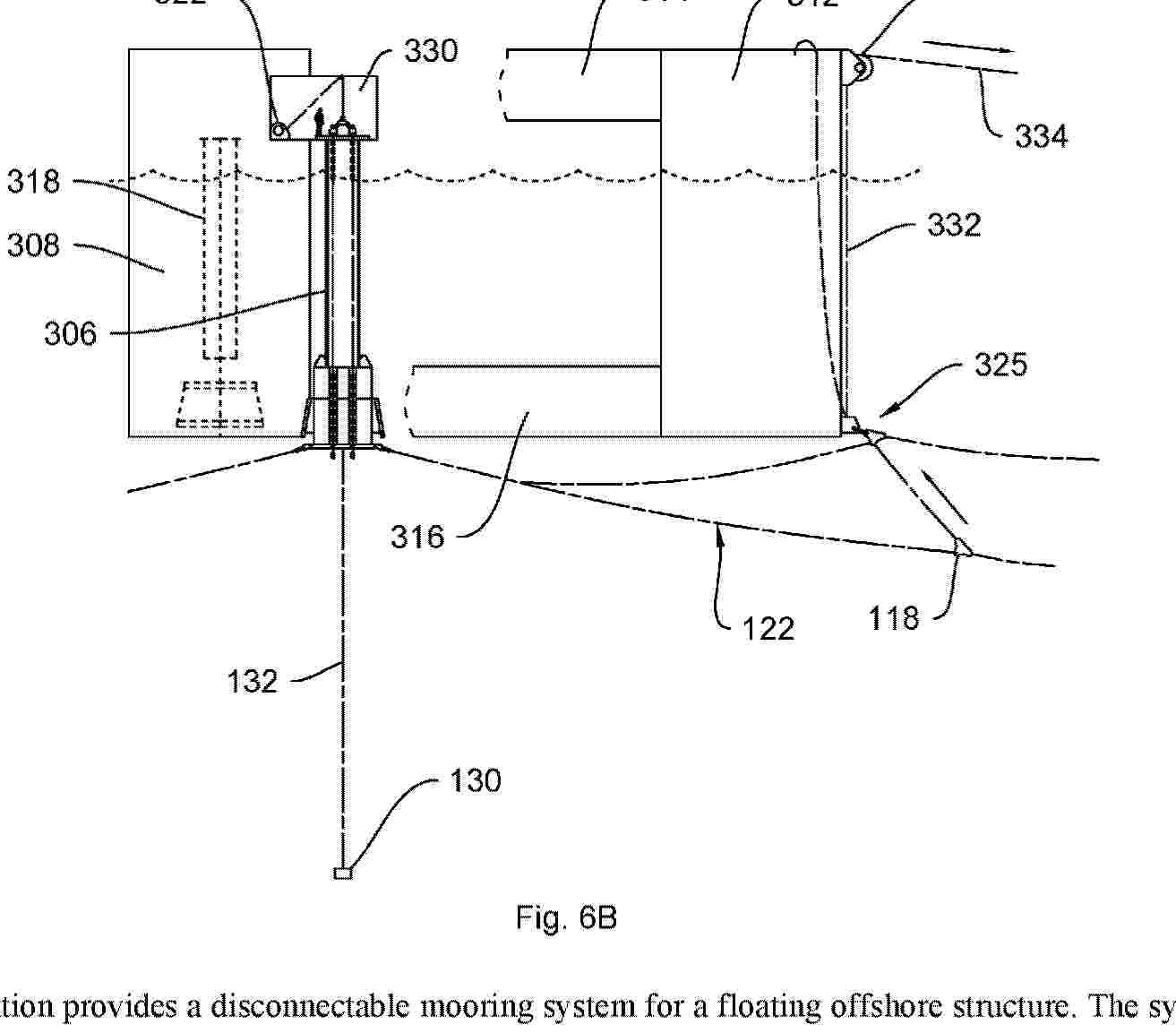
The invention provides a disconnectable mooring system for a floating offshore structure. The system may comprise: a buoy comprising a connector which enables connection and disconnection of the buoy from the floating structure. The system has a disconnected configuration in which the buoy is not connected to the floating structure and the buoy at least partially supports a dynamic riser conduit above the seabed. The system has a connected configuration in which the buoy is connected to the floating structure; and wherein the system is configured to enable pull-in of the buoy to the connected configuration and pull-in of the dynamic riser to a connection position. Aspects of the invention include related pull-in sequences, independent through connection of first and second dynamic riser conduits, and conductive coupling of a dynamic riser conduit to a floating structure. Further aspects of the invention include related rapid / emergency disconnect systems and methods, use a clump weight in an installation sequence, connection structures and buoy configurations, and rope connectors.
Resumen de: WO2026082200A1
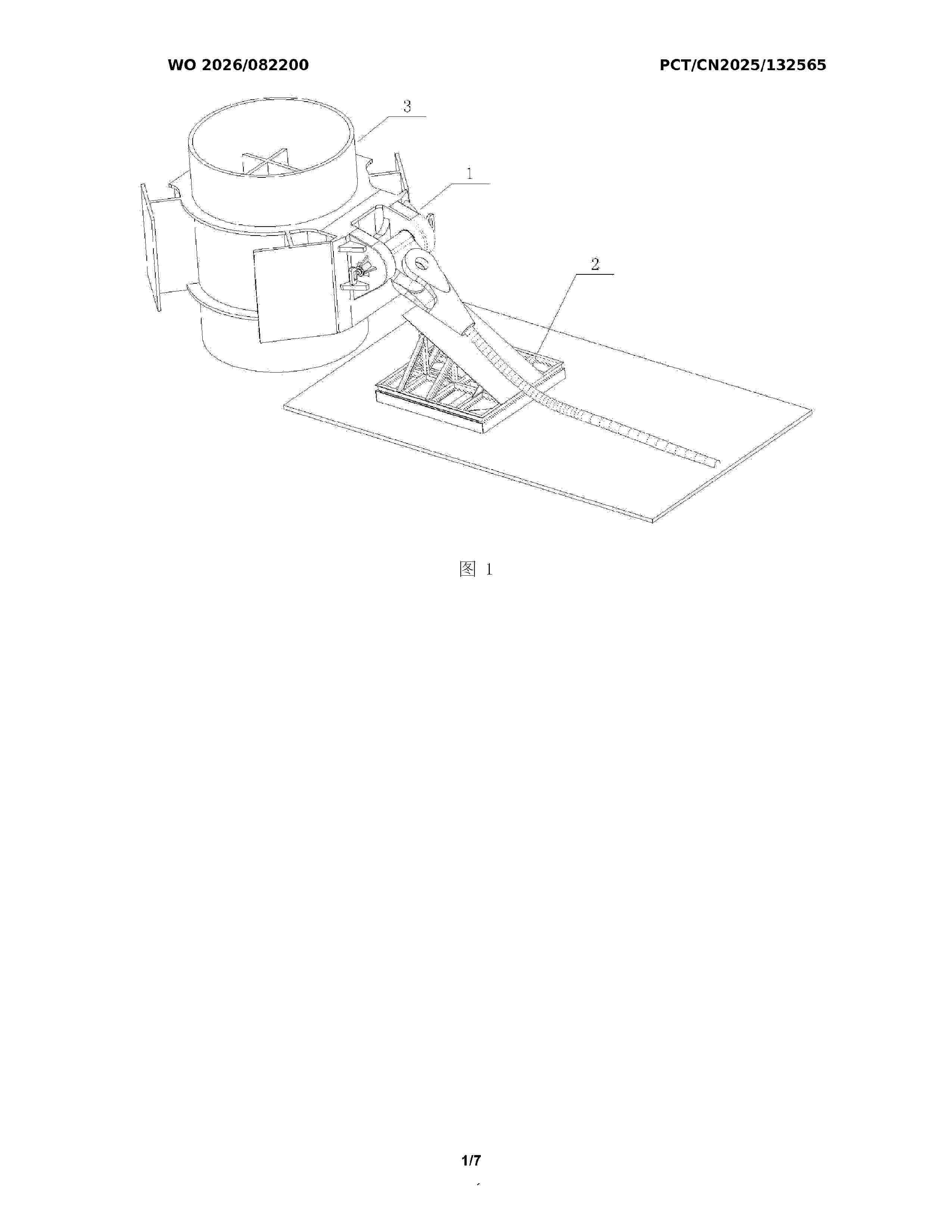
The present invention relates to the technical field of mooring connection of tension-leg floating wind turbine platforms. Disclosed is a pile foundation connection device for a tension-leg floating wind turbine platform. The pile foundation connection device comprises a bottom connection mechanism and a steel cable protection mechanism, wherein the bottom connection mechanism comprises a welding back plate, a tongue plate is provided on the welding back plate, the upper end of the tongue plate is connected to a steel cable socket by means of a pin shaft, and a steel cable is connected to the steel cable socket, such that the steel cable is capable of two rotational degrees of freedom; both ends of the tongue plate are locked and fixed by means of locking mechanisms; and the steel cable protection mechanism is located on one side of a pile foundation, and the steel cable is placed on the steel cable protection mechanism after the steel cable is connected, so as to prevent over-bending damage to the steel cable when same is pre-laid on the seabed. The present invention features a simple structure, a reliable performance and convenient operation, and can adapt to underwater quick connection; and the entire operation process only requires the assistance of one ROV, thereby simplifying the tie-back installation procedure of mooring lines and anchoring devices for a tension-leg wind turbine platform, and reducing the mooring and installation costs of the tension-leg wind turbine p
Resumen de: US20260109633A1
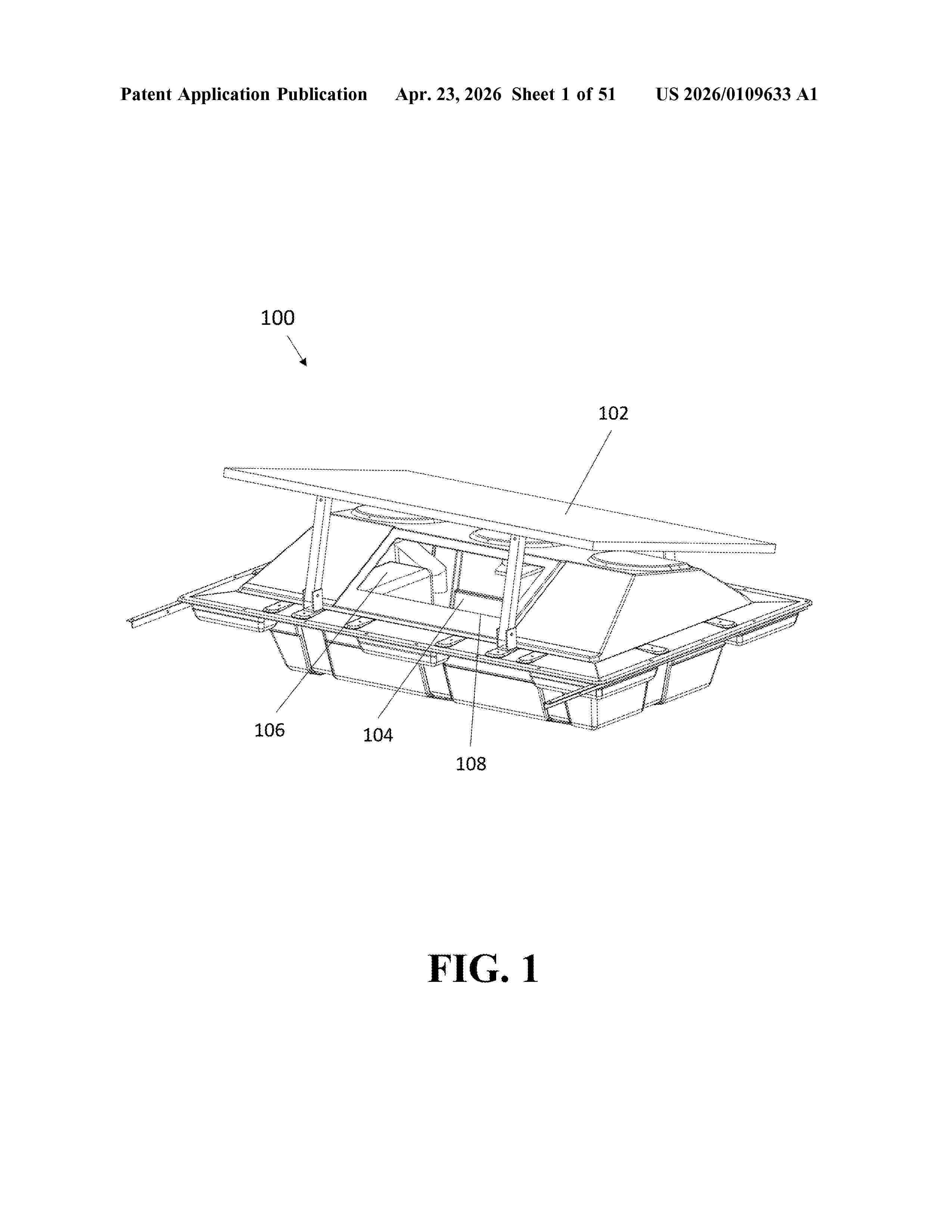
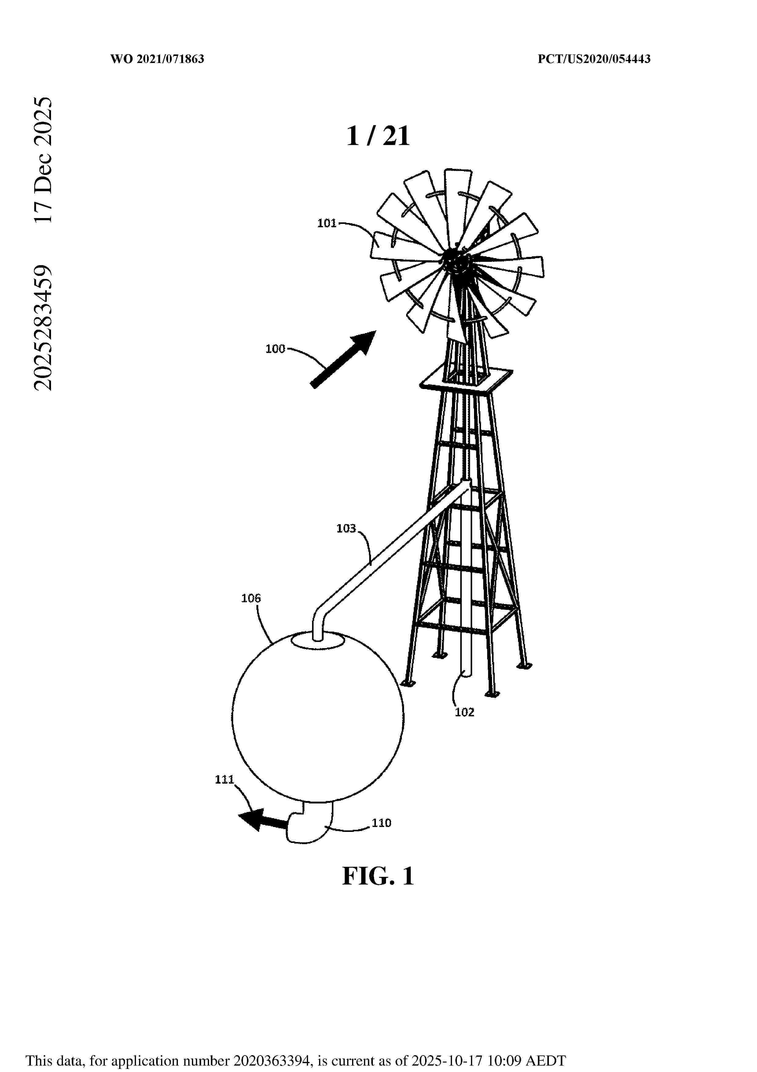
0000 Disclosed herein are devices, systems, and methods for water aeration and/or circulation, including, but not limited to, floating, onboard renewable energy-powered aeration for aquaculture ponds and/or other man-made and/or natural bodies of water (e.g., tanks, farm ponds, and reservoirs). In at least one embodiment, an aeration system has one or more photovoltaic (PV) panels to provide power to the aeration system. In at least one embodiment, the aeration system captures wind energy as an optional secondary power source. The aeration system may be either a battery-power or a direct-power system. The aeration system may also provide programmable settings. The system can be modular and scaled and/or customized to fit user needs. The aeration system may also include one or more float modules having an internal cavity, one or more pontoons and/or pontoon accessories for blocking and/or directing air and/or water flow, and/or one or more novel diffusers.
Resumen de: WO2024256782A1
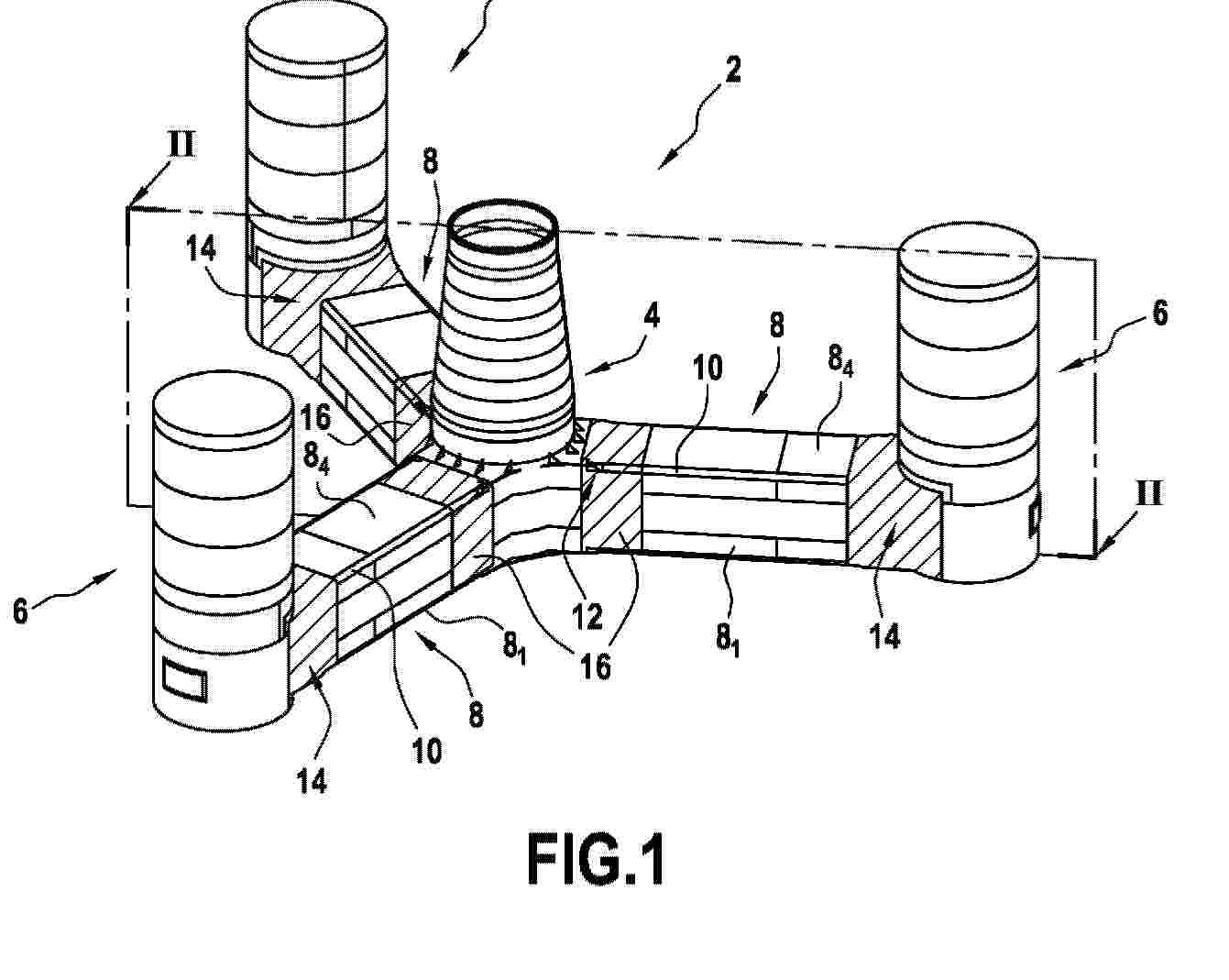
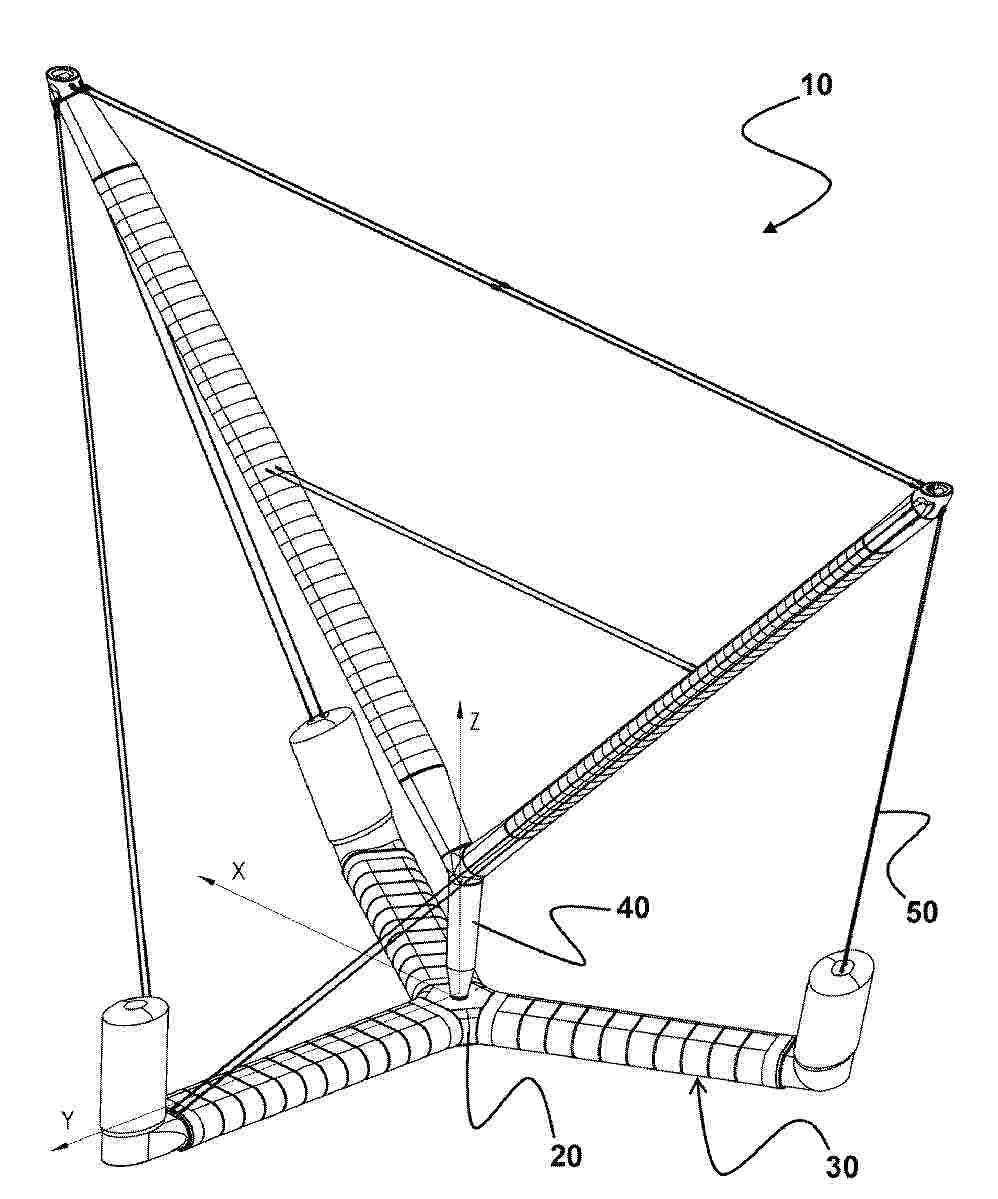
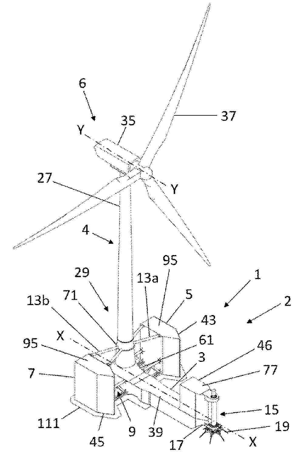
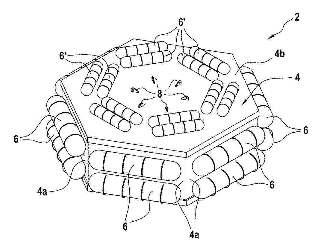
The invention relates to a semi-submersible float (2) for an offshore wind turbine, comprising at least three vertical columns (4, 6), one of which is intended to receive a wind turbine mast, the vertical columns being connected together by pontoons (8) each formed by a plurality of planar panels (81 to 84) which are assembled together at edges (10) extending longitudinally between two columns, the edges of the pontoons being rounded and connected at each of their longitudinal ends to a column via a transition piece (12).
Resumen de: WO2024255979A1
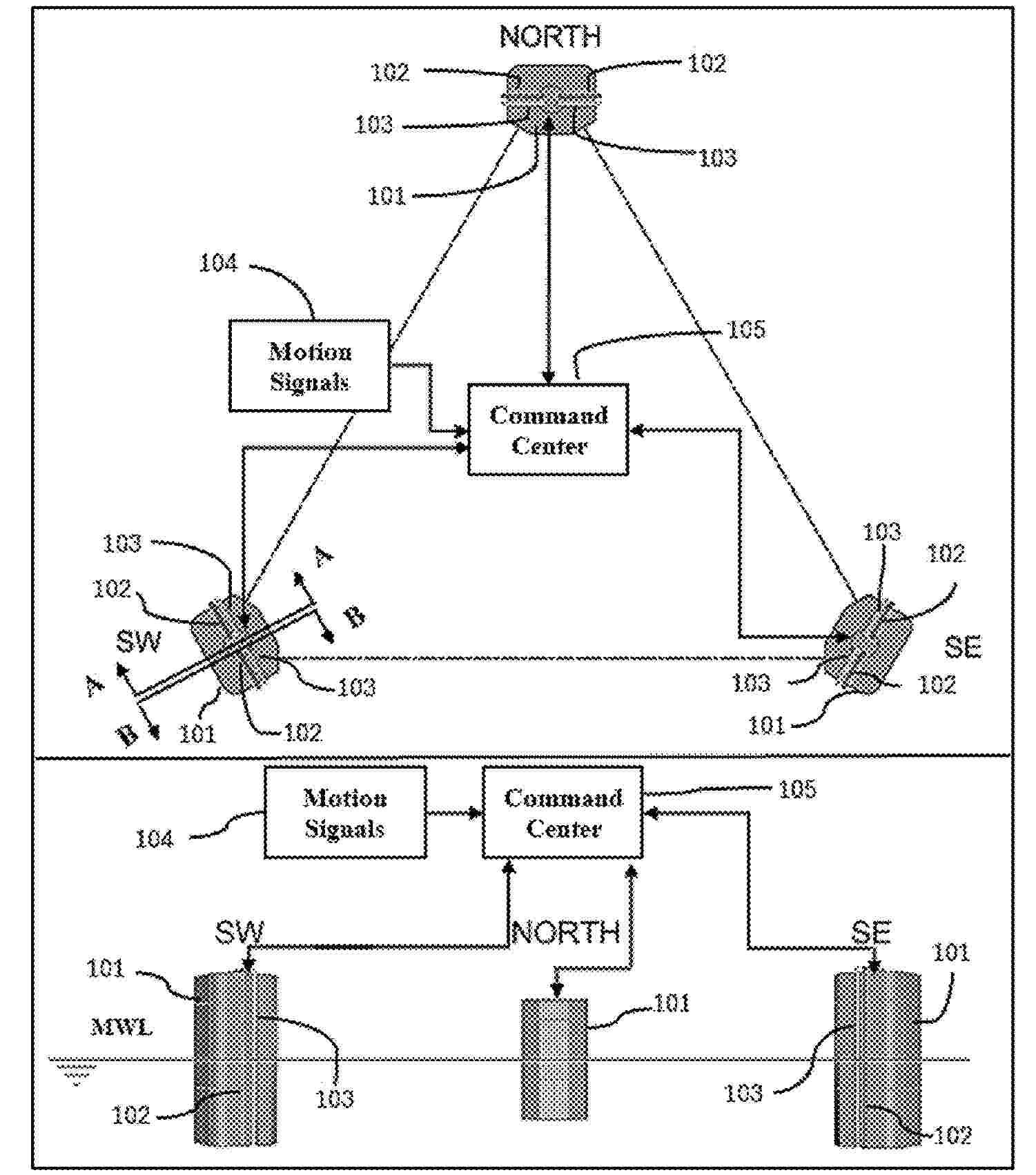
Disclosed is a method for controlling a floating wind turbine system. The floating wind turbine system comprises a floating platform, a tower mounted to the floating platform and a nacelle. The method comprises receiving, from one or more sensors of the floating wind turbine system, a signal indicative of a vertical acceleration of the floating wind turbine system. The method comprises determining, based on the received signal, a sea state parameter indicative of an oscillation of the vertical acceleration. The method comprises controlling the floating wind turbine system based on the sea state parameter.
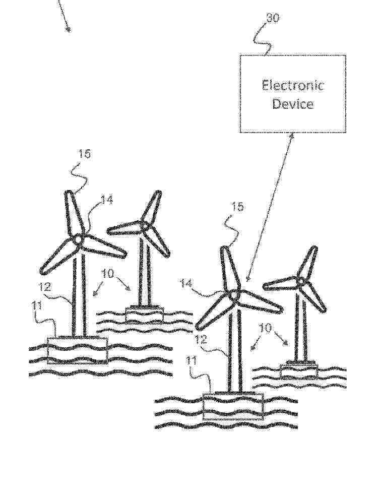
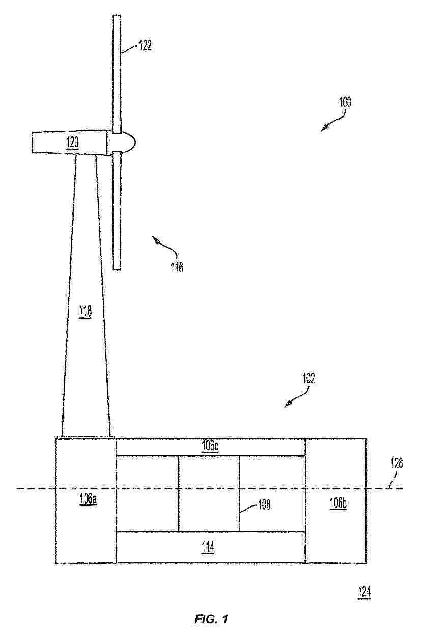
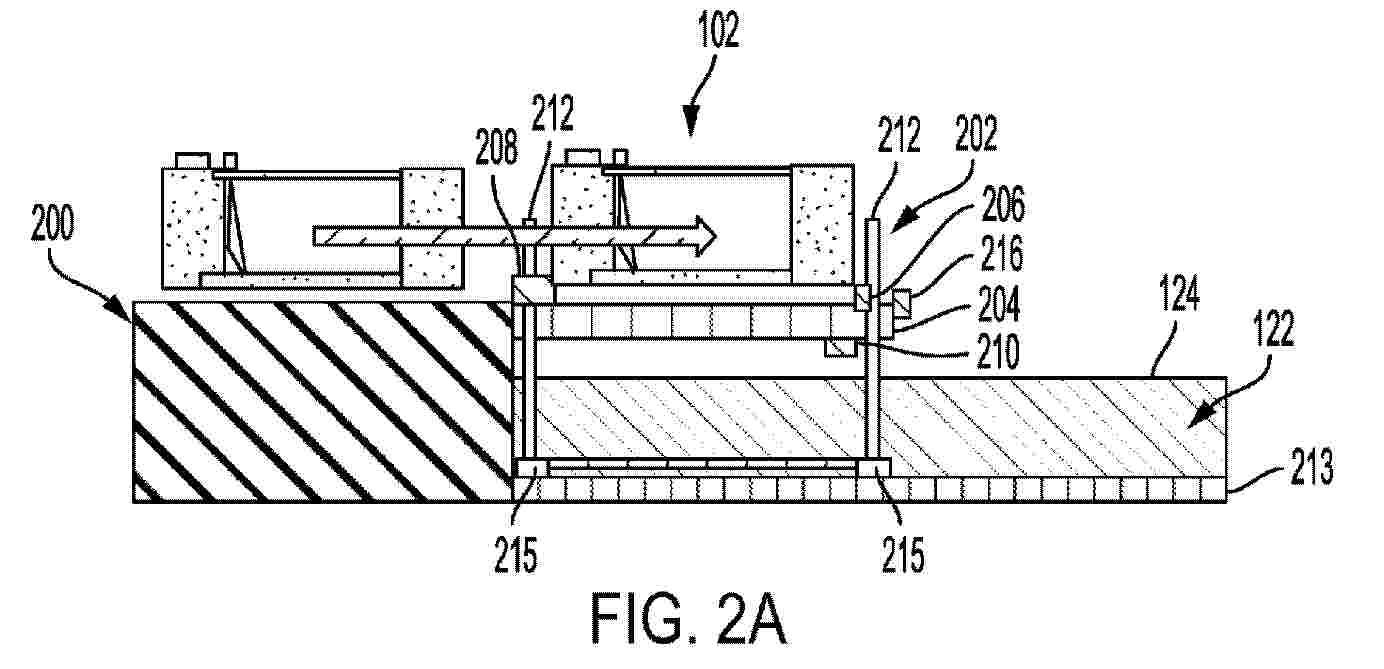
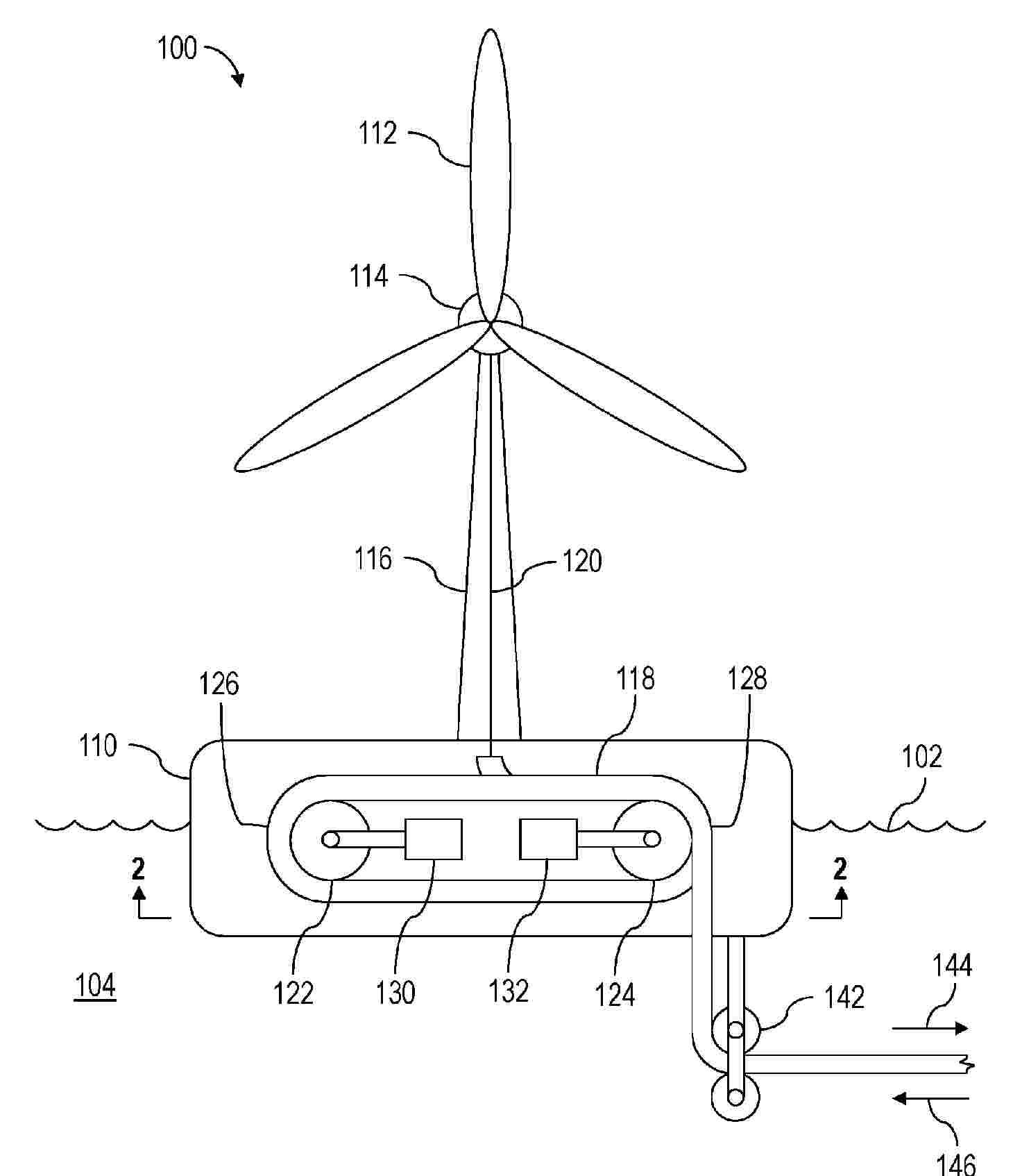
Resumen de: WO2026078372A1
An assembly system (100) for assembling an offshore structure (110), the assembly system comprising: a floating base (112) of the offshore structure (110); a lifting structure (120) configured to perform a landing operation, the landing operation comprising landing one or more components (114) of the offshore structure (110) onto the floating base (112); and a heave reduction system configured to selectively adjust a draft of the floating base (112) during the landing operation. A method (500) of assembling an offshore structure is also disclosed.
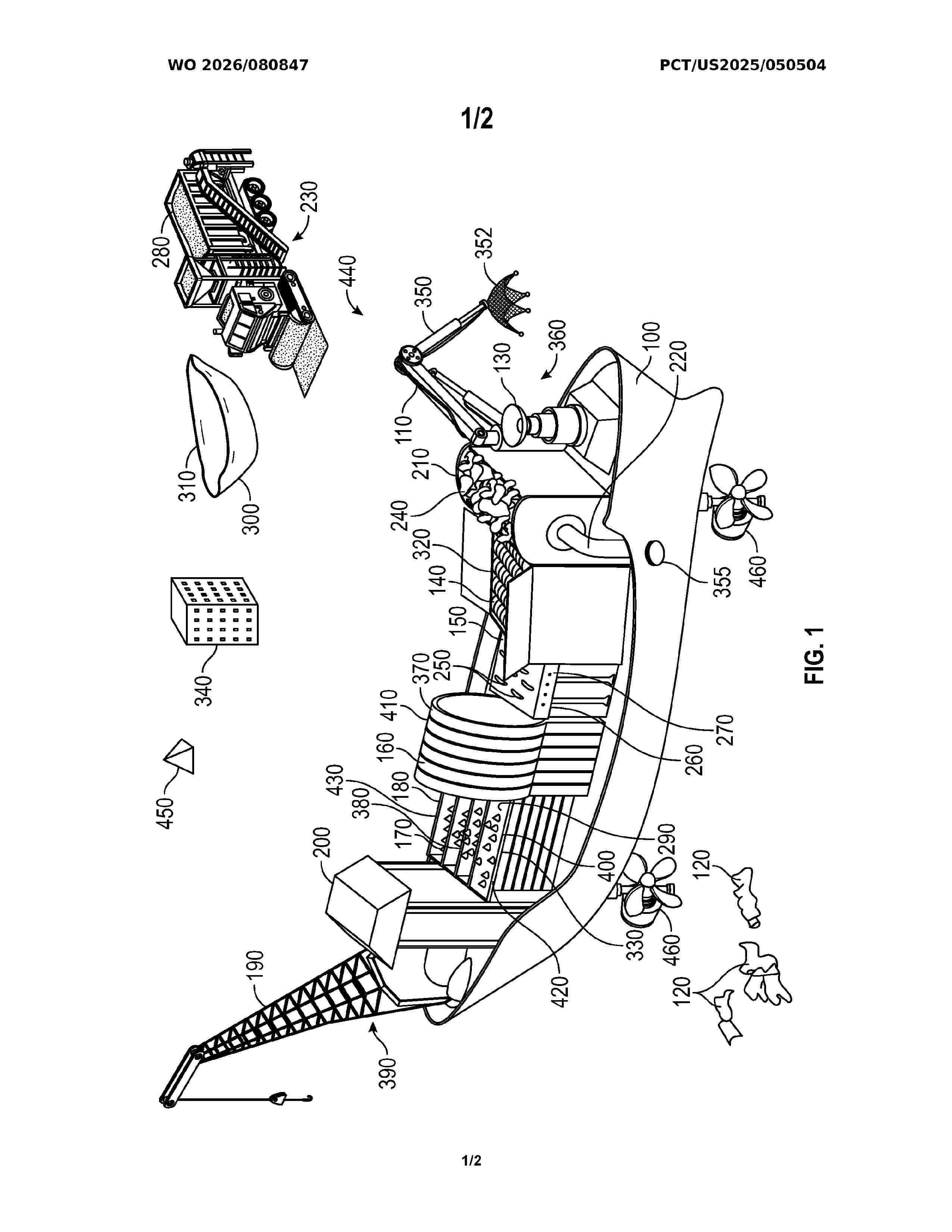
Resumen de: WO2026080847A1
A marine vessel designed for the collection, shredding, and pelletizing of oceanic plastic waste. The vessel uses renewable energy sources such as solar panels and wind turbines to power onboard systems, including Al-enhanced sensors that detect and target high-density areas of plastic debris. Once collected, the plastic is shredded and processed into uniform plastic pellets optimized for use in plastic asphalt production. The vessel also includes storage compartments for the pellets and a crane system for transferring containers filled with pellets to adjacent vessels or shore-based transport. This integrated system addresses inefficiencies in traditional ocean cleanup methods by enabling immediate onboard processing, reducing transportation needs, and repurposing plastic waste into a valuable industrial resource, while significantly minimizing environmental impact through sustainable energy use.
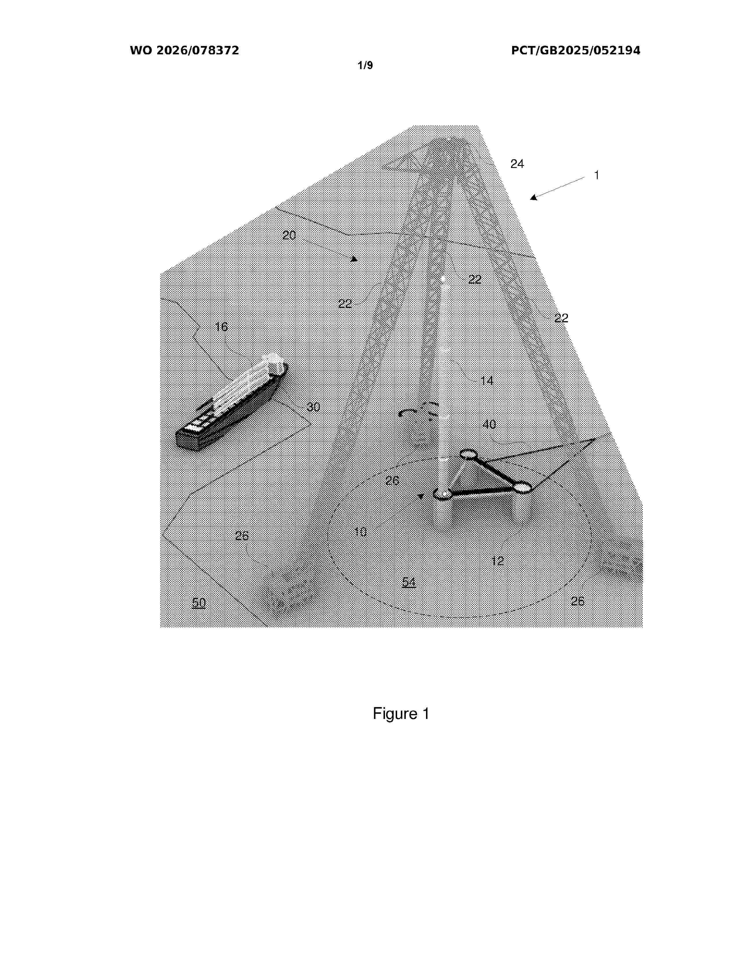
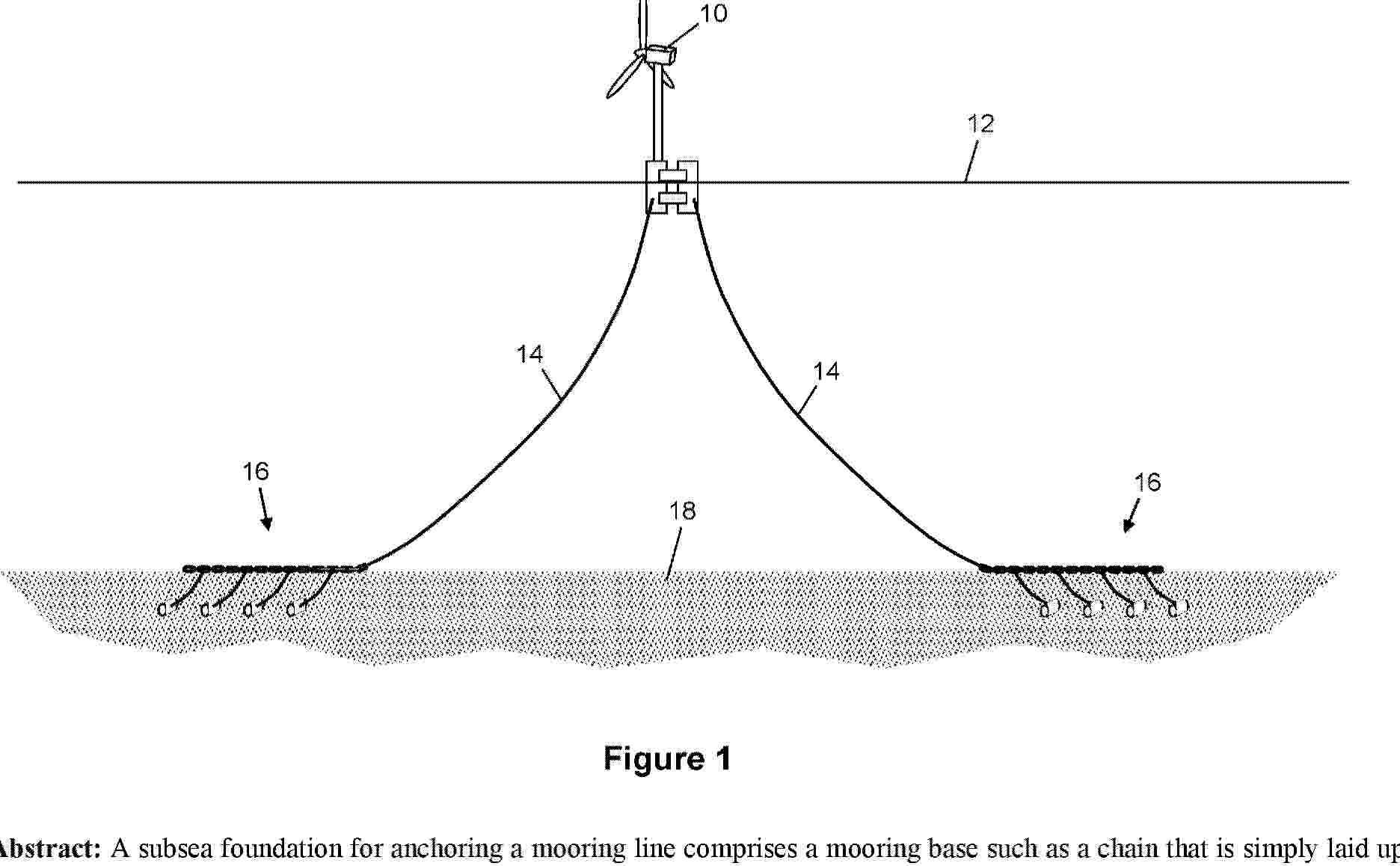
Resumen de: AU2024354596A1
A subsea foundation for anchoring a mooring line comprises a mooring base such as a chain that is simply laid upon the seabed in a straight, curved or looped configuration, hence extending across the seabed substantially parallel to the seabed. The mooring base is then anchored by one or more deadman anchors that are embedded in the seabed soil. For this purpose, one or more links extend through the soil to couple the mooring base to the or each deadman anchor. One or more mooring lines can then be coupled to the mooring base.
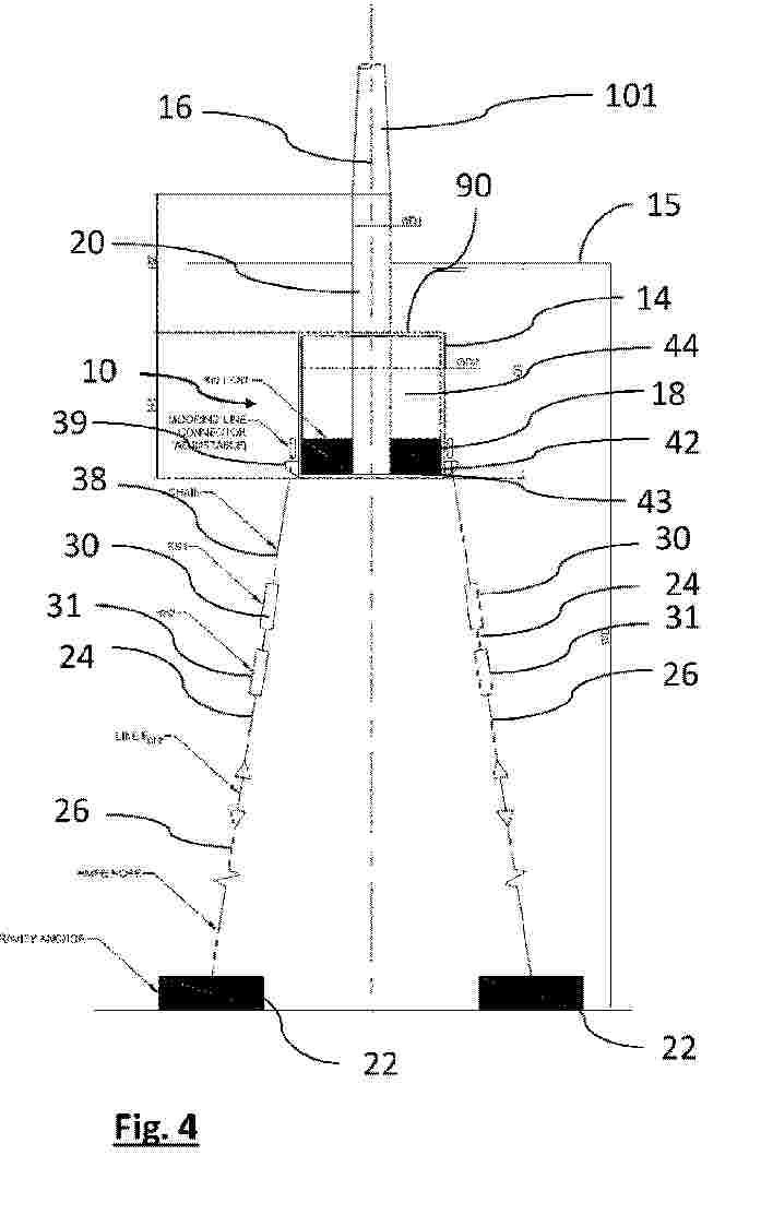
Resumen de: AU2024356626A1
A connecting system (100) for connecting a weathervaning floating offshore support structure (200) of a wind turbine (201) to a pre-laid mooring system (300), the connecting system (100) comprising: - a turret element (1) comprising: a base (2) for being solidly connected to the pre-laid mooring system (300); a support element (3) comprising a switchgear (31) connectable to one or more submarine cables (400) and connectable to receive a power generated by the wind turbine (201); a columnar body (4) extending from the base (2) to the support element (3), and comprising an inner passage (41); and a bearing system (5) configured to rotatably connect the turret element (1) to the weathervaning floating offshore support structure (200); and - a slip-ring connector (6) comprising a first connecting part (61) for receiving the power generated by the wind turbine (201), and a second connecting part (62) cable-connectable to the switchgear (31).
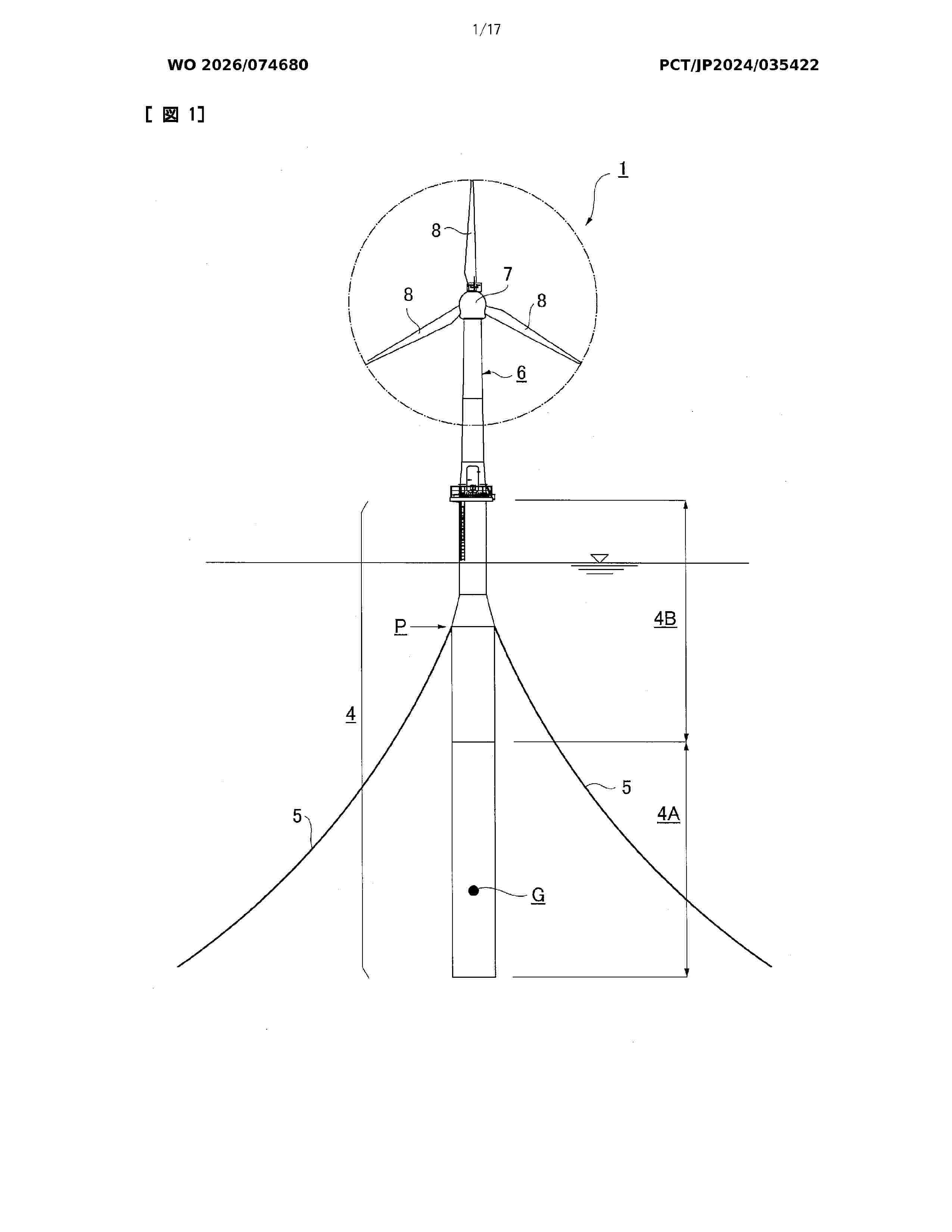
Resumen de: WO2026074680A1
Problem To efficiently construct a spar-type floating body at a low cost, and to simultaneously solve issues such as concrete temperature cracks and bending cracks. Solution A spar-type floating body 4 with the lower half thereof being imparted as a steel-concrete composite structure part 4A in which concrete C is cast to a prescribed thickness on the inner surface of an outer-shell steel member 10 that covers the outer periphery, and the upper half thereof having an outer-shell steel member 12 that covers the outer periphery and being imparted as a steel structure part 4B made entirely of steel members. In the steel-concrete composite structure part 4A, reinforcing bars embedded in the concrete C are formed by arranging assembly reinforcing bars 35 spaced at an interval P along the longitudinal direction of the floating body, each assembly reinforcement 35 comprising: an inner circumferential bar 36A arranged parallel to the outer-shell steel member 10 in a state of maintaining a prescribed cover K with respect to the concrete outer surface; and a zigzag-shaped truss bar 36B arranged so as to alternately connect, over each prescribed length, the inner circumferential bar 36A and the outer-shell steel member 10.
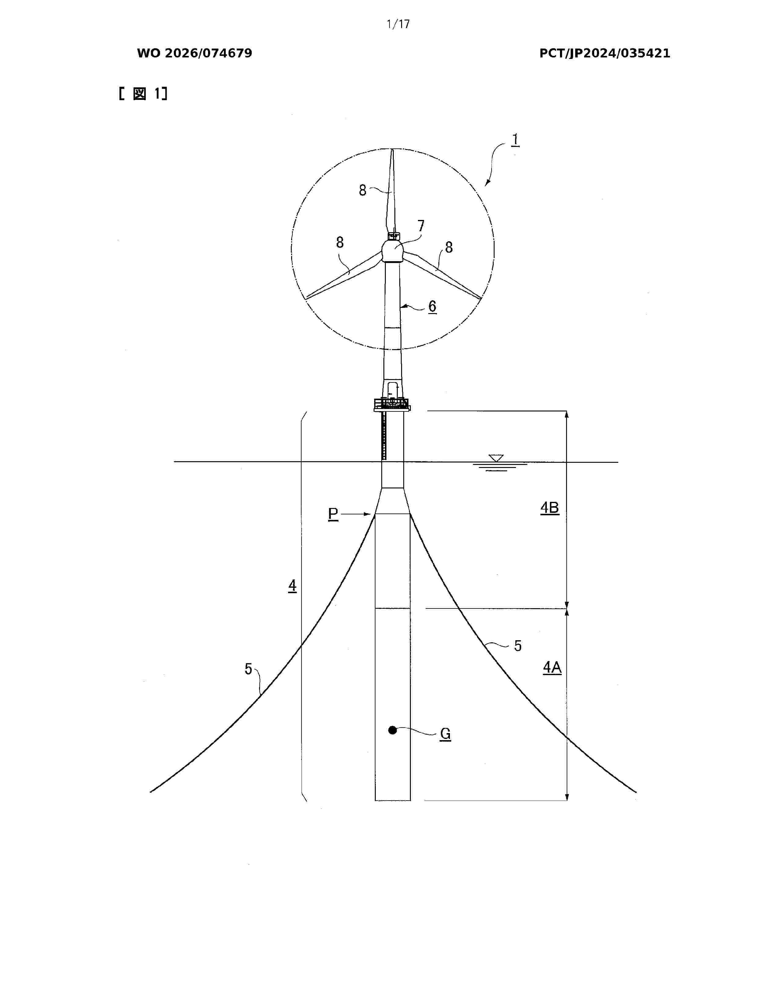
Resumen de: WO2026074679A1
Problem To enable efficient and low-cost construction of a spar-type floating body and to simultaneously solve problems such as thermal cracking and bending cracking of concrete. Solution In a spar-type floating body 4, the lower half side is a steel-concrete composite structure part 4A in which concrete C is cast in a predetermined thickness on the inner surface side of an outer shell steel member 10 covering the outer periphery. In the steel-concrete composite structure part 4A, reinforcing bars placed in the concrete C include polygonal first reinforcing bars 35 and second reinforcing bars 36 disposed alternately in a staggered manner at intervals in the longitudinal direction of the floating body, the first reinforcing bars 35 and the second reinforcing bars 36 being constituted by a large number of joint parts a welded to the outer shell steel member 10 over a predetermined length range and at predetermined intervals in the circumferential direction of the outer shell steel member 10, and chord parts b linearly connecting ends of adjacent joint parts a, a. At the center position of each chord part b of the first reinforcing bars 35 and the second reinforcing bars 36, a predetermined cover to the outer surface of the concrete is ensured.
Resumen de: EP4722095A1
A floating platform system can be provided to facilitate mounting of and for supporting a structure on a floating platform. For example, the floating platform system can include the floating platform. The floating platform system can also include a ballast receiving volume inside the floating platform for receiving a ballasting liquid. The floating platform system can further include a mounting surface on the floating platform for mounting a structure. Additionally, the floating platform can include a downwardly-oriented stabbing guide.
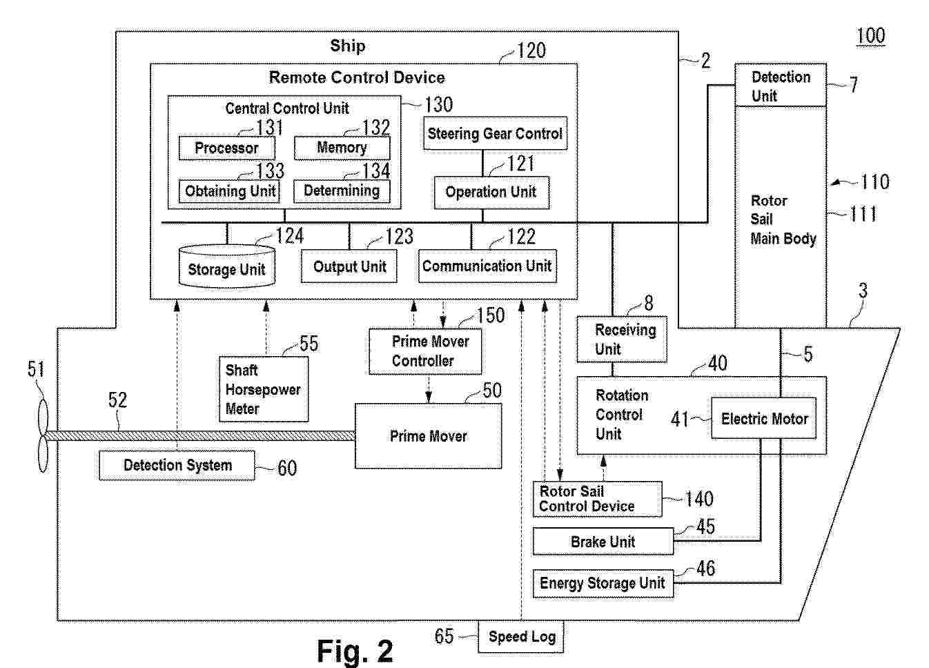
Resumen de: EP4722100A1
A rotor sail system includes: a vertical support post extending in a vertical direction from a hull; a blade connected to a shaft, the blade being rotatable about the shaft, the shaft extending in a predetermined direction with reference to the vertical support post; a detection unit detecting a wind direction and a wind speed in a navigation area of a ship; a receiving unit receiving a thrust command to specify a thrust of the ship; and a rotation control unit capable of controlling a rotational speed of the blade about the shaft. The rotation control unit controls the rotational speed of the blade about the shaft based on the received thrust command and a detection result of the wind direction and the wind speed detected when the thrust command is received.
Resumen de: WO2024246109A1
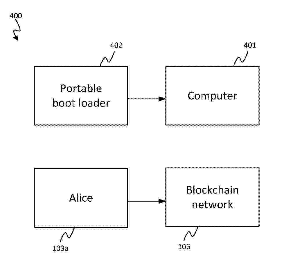
A computer-implemented method for booting a device using a portable boot loader device, wherein the portable boot loader device comprises a boot loader and operating system files, wherein a blockchain comprises a boot loader transaction, wherein the boot loader transaction comprises an output locked to a master public key, and wherein the boot loader transaction comprises a first signature signing the boot loader and a second signature signing the operating system files, and wherein the method comprises: obtaining the boot loader transaction; verifying the first signature using the master public key; verifying the second signature using the master public key; and loading the operating system files using the boot loader.
Resumen de: WO2024246109A1
A computer-implemented method for booting a device using a portable boot loader device, wherein the portable boot loader device comprises a boot loader and operating system files, wherein a blockchain comprises a boot loader transaction, wherein the boot loader transaction comprises an output locked to a master public key, and wherein the boot loader transaction comprises a first signature signing the boot loader and a second signature signing the operating system files, and wherein the method comprises: obtaining the boot loader transaction; verifying the first signature using the master public key; verifying the second signature using the master public key; and loading the operating system files using the boot loader.
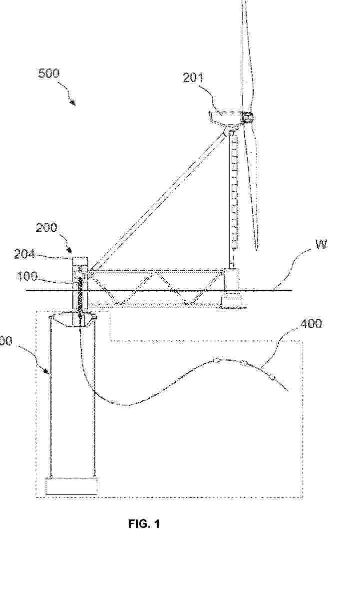
Resumen de: WO2026069517A1
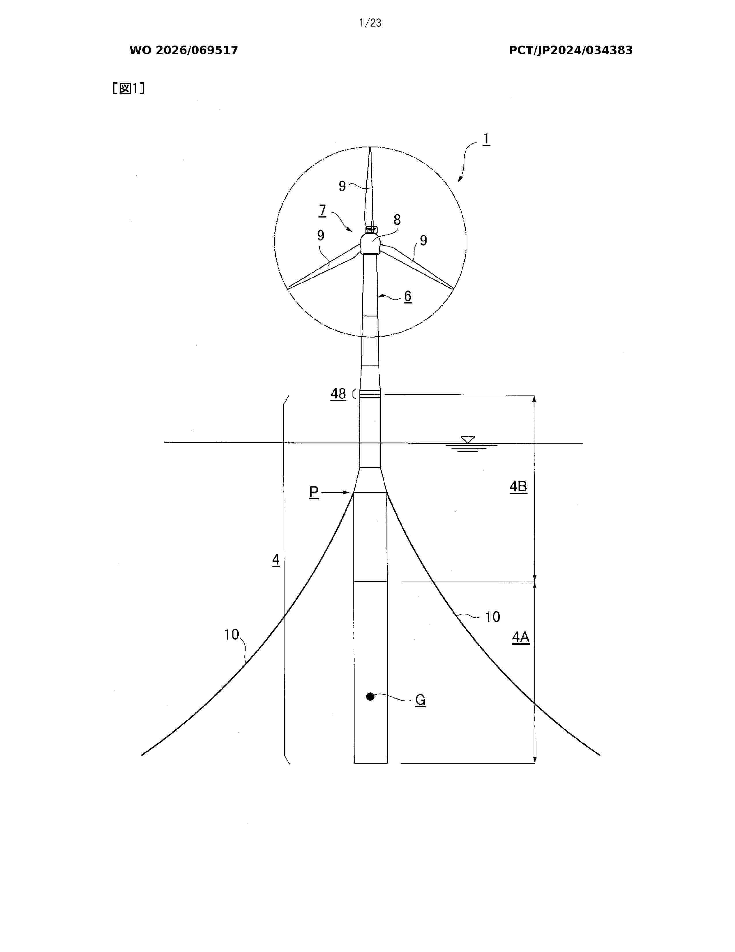
Problem To provide a connection device with which it is possible to stably and efficiently connect an upper structure to a floating body. Solution The connection device 48 is composed of: a floating body-side connection device 49 provided at the upper end of a floating body 4; and a tower-side connection device 50 provided at the lower end of a tower 6. The floating body-side connection device 49 has at least two introduction tubes 54, 55 embedded on the upper surface side of a bottom plate 51, and the tower-side connection device 50 has a plurality of introduction pins 59, 60 provided on the lower surface side of a top plate 56 in correspondence to the introduction tubes 54, 55. The introduction tubes 54, 55 are constituted by engagement tube parts 54A, 55B in which elliptical through-holes are formed, and funnel parts 54B, 55B, and the introduction pins 59, 60 have elliptical cross sections so as to correspond to the elliptical through-holes. A connection flange 53 of the floating body-side connection device 49 and a connection flange 58 of the tower-side connection device 50 are fastened by a bolt and nut member 62 while the corresponding introduction tubes 54, 55 and the introduction pins 59, 60 are engaged with each other.
Resumen de: US20260091857A1
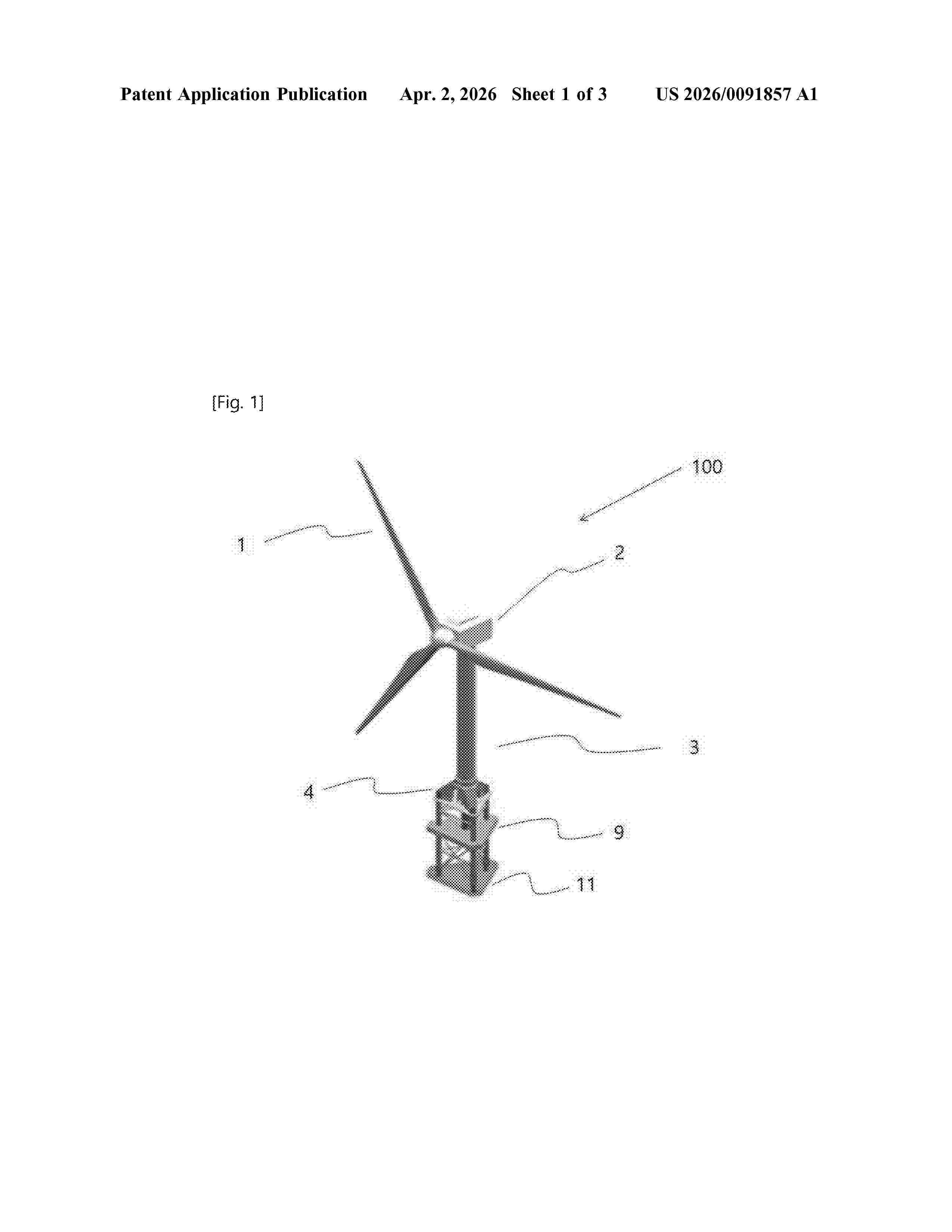
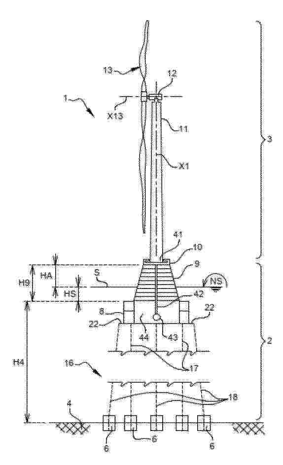
A tower-integrated offshore wind power floating body includes a tower formed under a power generation unit, transition pieces (TPs) spaced apart from a lower circumference of the tower at regular intervals, a seating part formed under the tower and the TP to support lower portions of the tower and the TP, a reinforcement column having the same axis as a vertical central axis of the tower and formed under the seating part, a buoyancy part formed under the reinforcement column, a ballast part formed under the buoyancy part such that the ballast part is spaced a length from the buoyancy part, a brace formed between the seating part and the buoyancy part, a brace formed between the buoyancy part and the ballast part, and main columns arranged in a vertical direction in the TP, the seating part, the buoyancy part, and the ballast part, and the main columns.
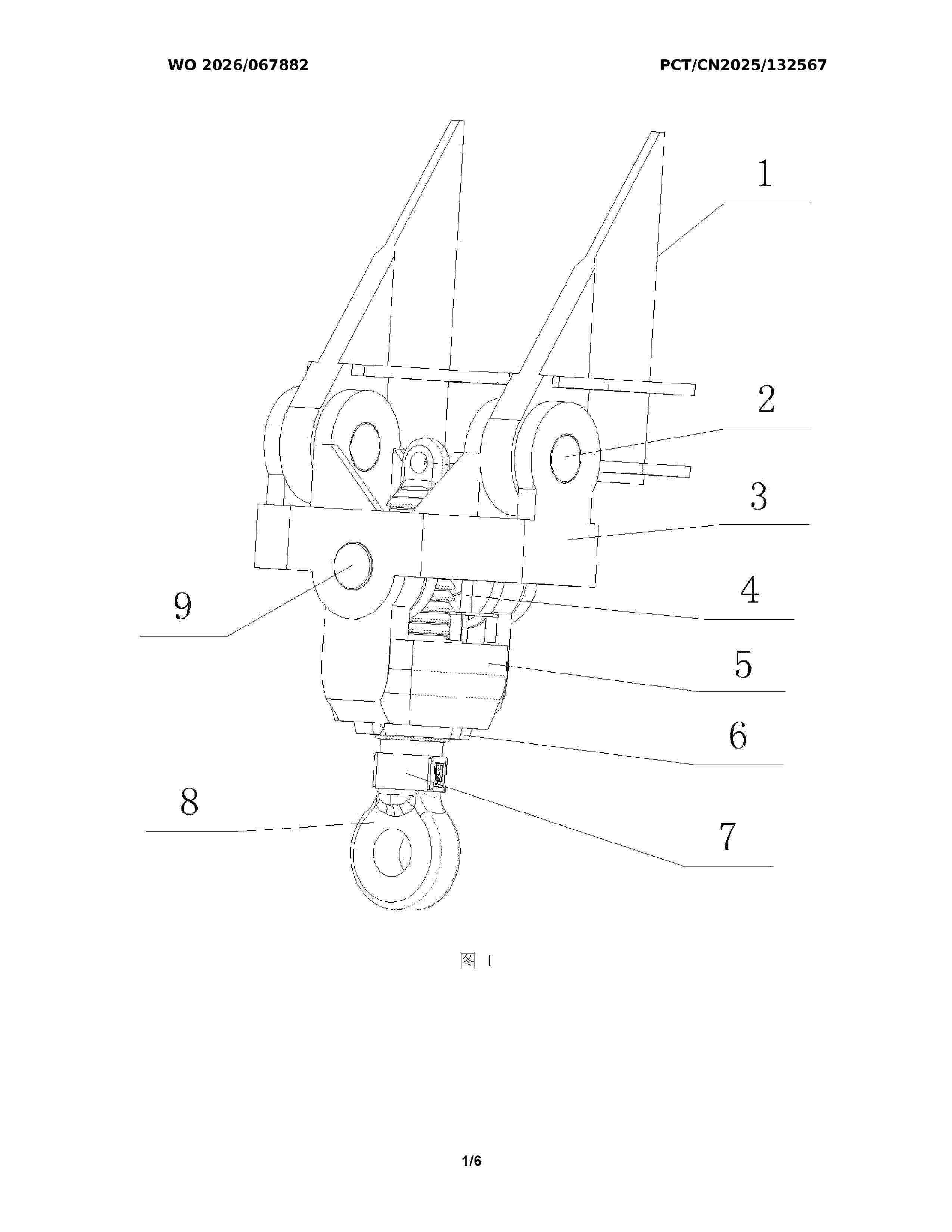
Resumen de: WO2026067882A1
The present invention relates to the technical field of the mooring connection of floating wind power platforms. Disclosed is a high-precision floating body mooring adjustment device based on online tension monitoring. An upper lifting frame is connected to a welding back plate by means of upper rotating shaft pins, and is connected to a lower lifting frame by means of lower rotating shaft pins; a locking mechanism is provided in the lower lifting frame; a toothed column runs through the lower lifting frame and the upper lifting frame, and is locked by means of the locking mechanism; hydraulic cylinders are symmetrically provided on two sides of the lower lifting frame, and by means of the hydraulic cylinders, the entire locking mechanism is moved vertically; and a tension monitoring mechanism is provided at the lower end of the toothed column, and monitors and measures, in real time, the load by means of remote software. The present invention features a high adjustment precision and a short operating cycle, has functions including reliable connection, length adjustment of mooring lines, self-locking and self-tightening, reverse release and load measurement, can adjust the length of mooring lines with high accuracy, simplifies the installation process of reconnection and tensioning of mooring lines of a tension-leg wind power platform, and reduces the mooring and installation costs of the tension-leg wind power platform.
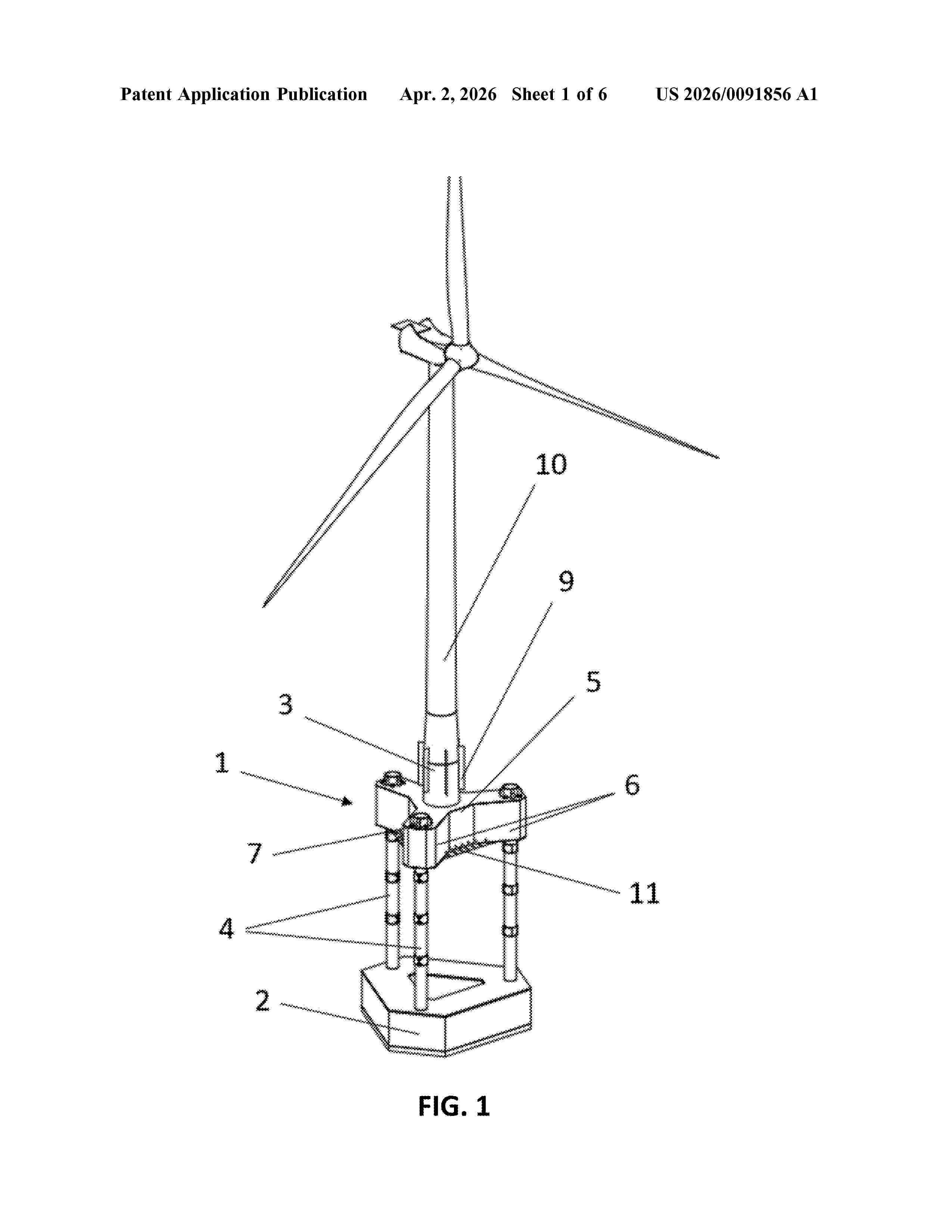
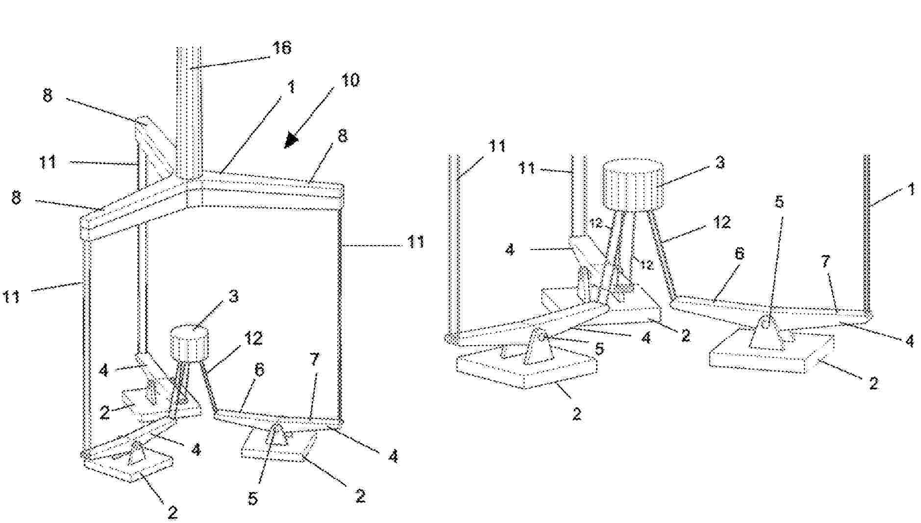
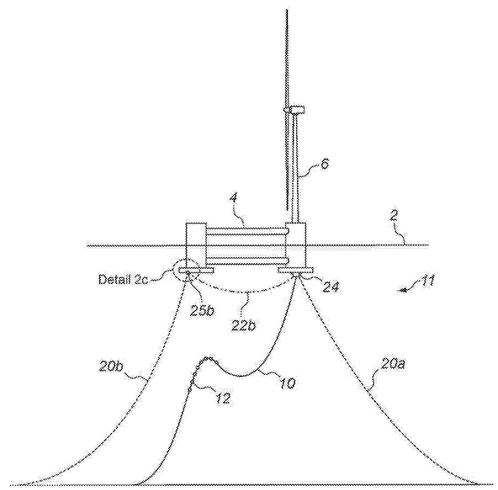
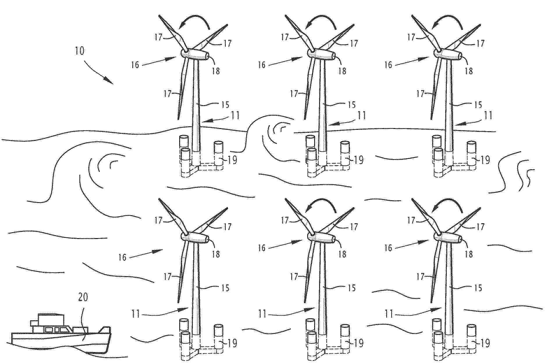
Resumen de: US20260091856A1
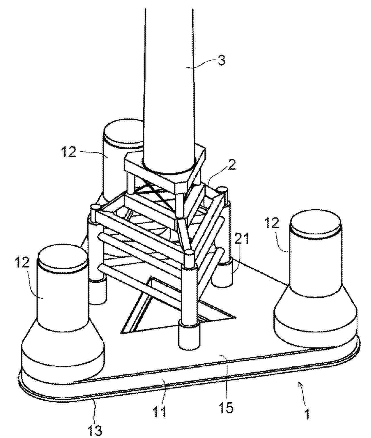
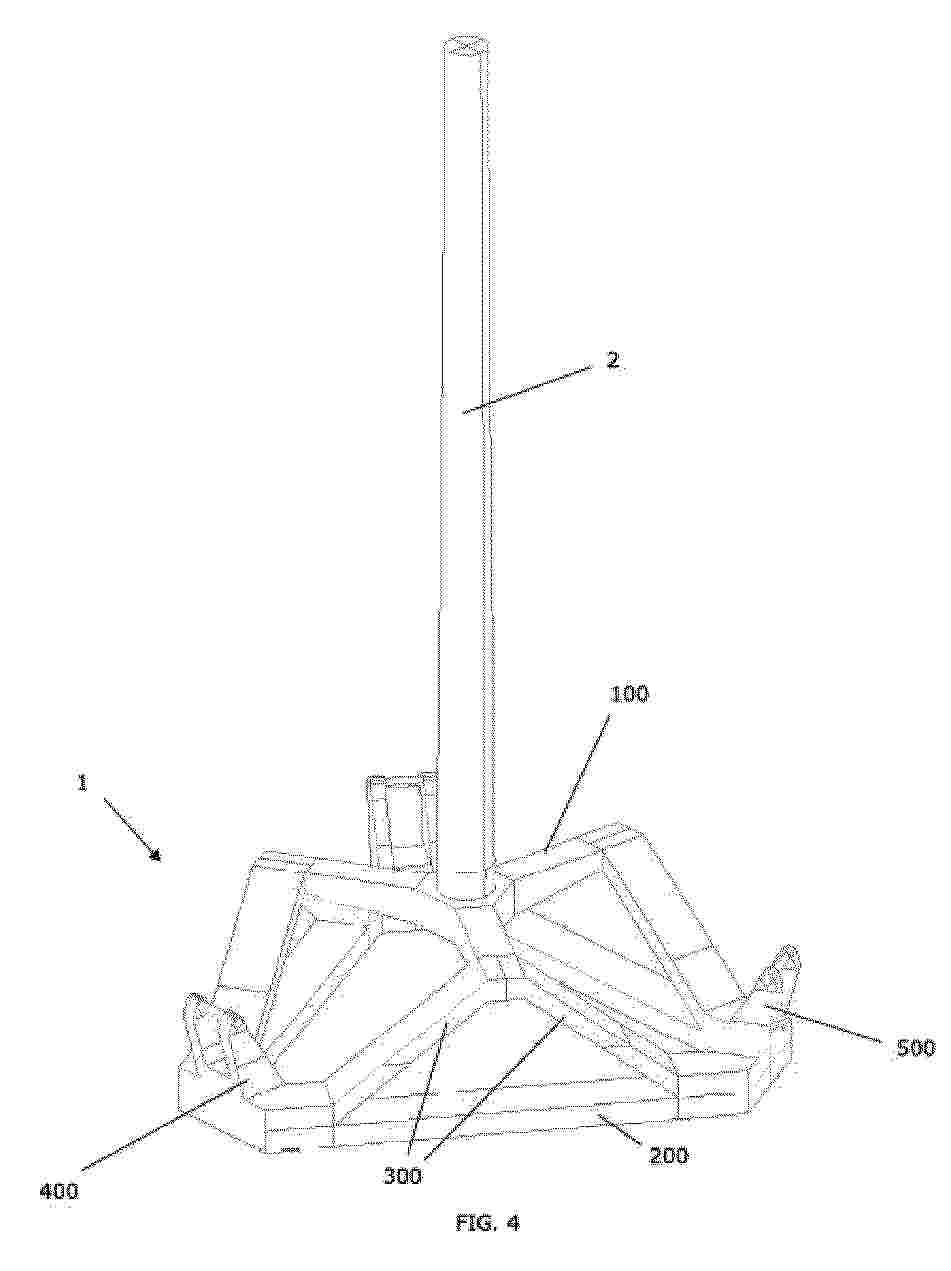
The present invention relates to a device for supporting an offshore wind turbine tower. The device comprises a first body (1), a support body (3) attached to the first body (1), a second body (2) and a plurality of legs (4) attached to the second body (2). The support body (3) has a cylindrical interior and is configured to provide support for and connection of a wind turbine tower (10). The first body (1) comprises a central portion (5) connected to the support body (3) and a plurality of hollow arms (6), connected with the central portion (5). Each hollow arm (6) comprises a through-hole (7) configured to allow a leg (4) to pass through the through-hole. The first body (1) has a volume and a weight configured to provide, when empty, a buoyancy of at least 20% of the weight of the entire device, the weight of the first body (1) being less than 8% of the weight of the entire device. The legs (4) and/or the first body (1) have a locking system configured to lock the relative position between the legs and the first body.
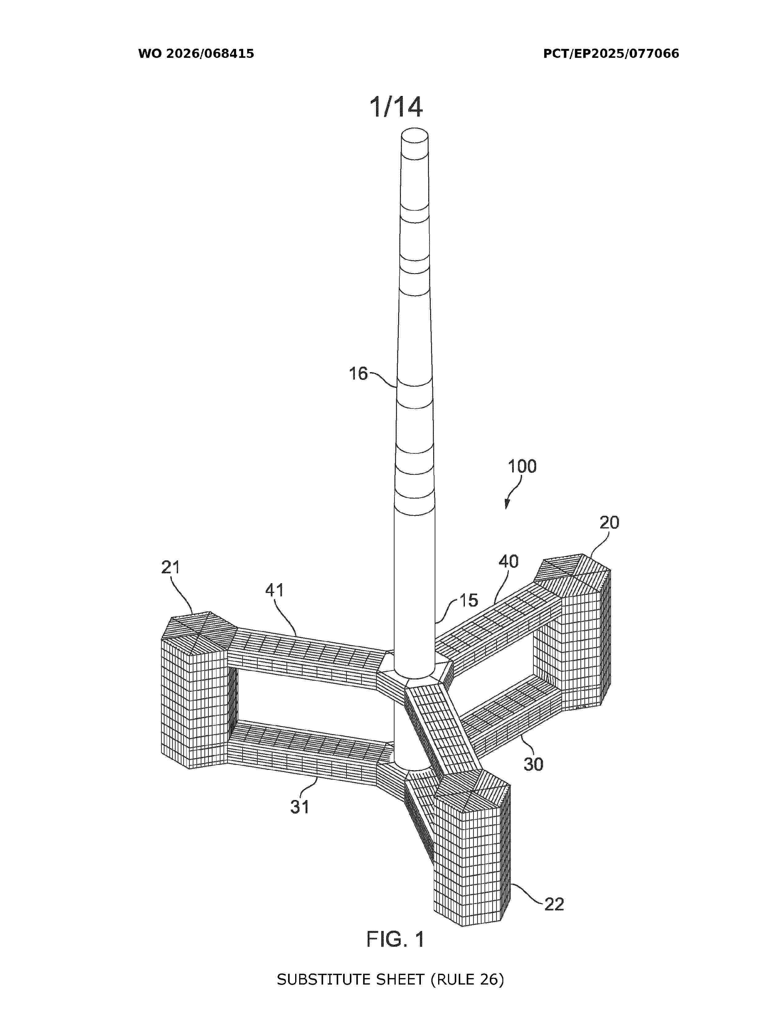
Resumen de: WO2026068415A1
A method of constructing a floatable foundation (100) for a wind turbine generator, the method comprises: assembling a hull (101) for the floatable foundation (100) at a shoreside yard (102), the hull (101) comprising three interconnected columns (20,21,22), each column (20,21,22) having a ballast tank (140-142) arranged at least partly therein and a ballast water filling interface (143-145) fluidly connected to the respective ballast tank (140-142); moving the hull (101) from the shoreside yard (102) to a floating position adjacent or spaced from the shoreside yard (102); and with the hull (101) in the floating position, filling each of the ballast tanks (140-142).
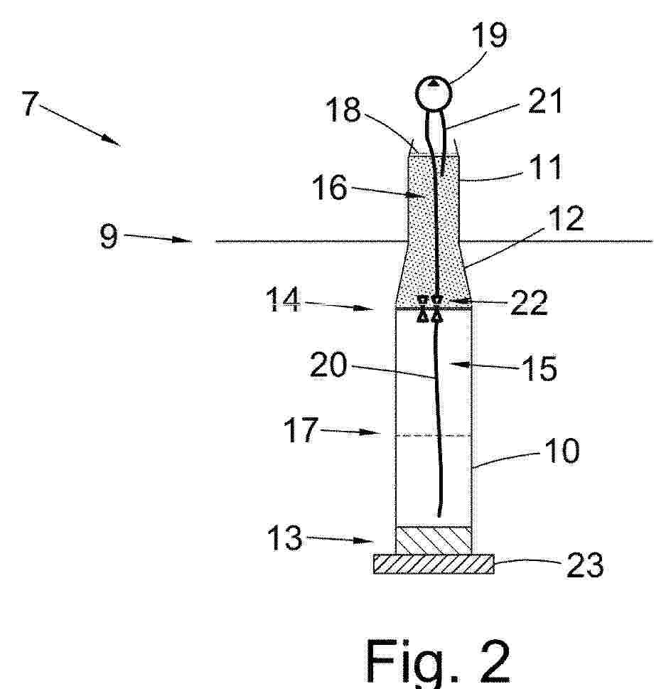
Resumen de: EP4717581A2
A floating spar platform 7 for supporting an offshore wind turbine comprises at least one first ballast tank 15 for holding adjustable ballast and at least one second ballast tank 16 for holding adjustable ballast. The second ballast tank 16 is arranged vertically higher than the first ballast tank 15, allowing a vertical distance between the bottom of the spar platform 7 and the centre of centre of gravity 31 of the spar platform 7 to be controlled by adjusting the amount of ballast held within the first and/or second ballast tanks 15, 16. This provides for control over the resonant response of the floating spar platform 7. During installation of a wind turbine on the floating spar platform 7, ballast associated with the spar platform may be adjusted in order to increase the vertical distance between the bottom of the spar platform 7 and the centre of gravity 31 of the spar platform 7, which reduces wave-induced resonant motions of the spar platform 7.
Resumen de: EP4717580A2
Offshore wind turbine systems and processes for installing same. The system can include a wind turbine generator can include a plurality of blades connected thereto. The system can also include a first support arm and a second support arm each having a first end and a second end. The system can also include a support structure that can be configured to float on a surface of a body of water that can include first, second, and third columns. The first end of the first support arm and the first end of the second support arm can each support the wind turbine generator at an elevation above the support structure. The second end of the first support arm can be connected to and supported by the first column. The second end of the second support arm can be connected to and supported Q by the second column.
Resumen de: WO2024240532A1
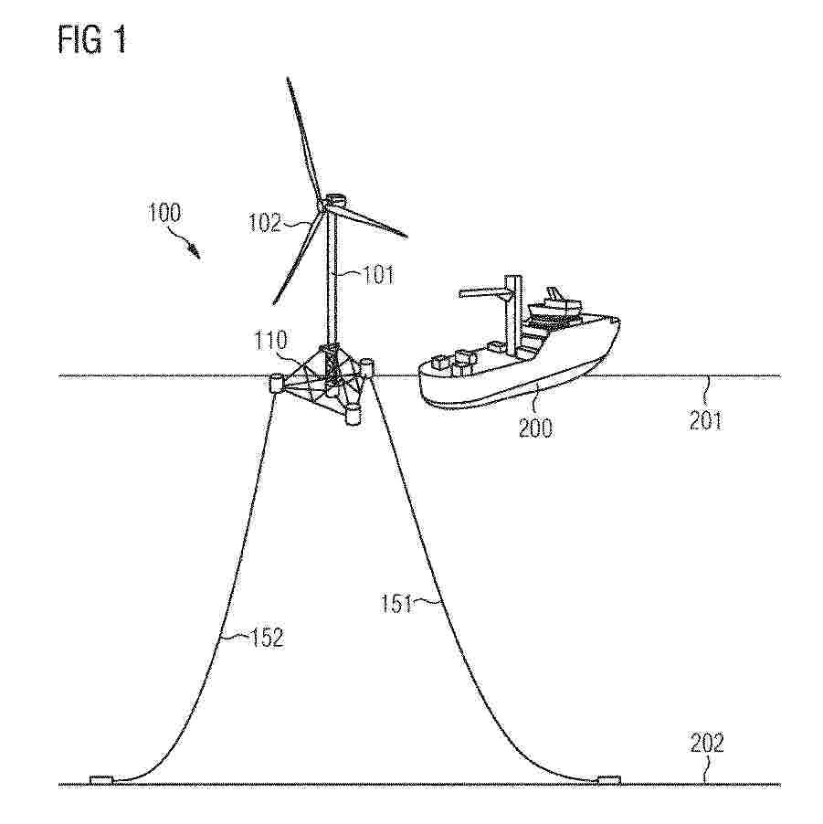
The invention describes a system and a method for connecting a service vessel (1) and a floating support structure (2) for a wind turbine (3). The service vessel comprises an aft coupling section (5) and vessel contact means (6), that can be lifted by elevation means, positioned on the aft coupling section (5), upward and downward between a higher contact position and a lower free position. The floating support structure (2) comprises a central coupling space (7) capable of receiving the aft coupling section (5) and support structure contact means (8) for interacting with the vessel contact means (6) when the aft coupling section (5) is centrally positioned in the coupling space (7) and the vessel contact means (6) are moved upward. The vessel contact means (6) are positioned at an altitude below the support structure contact means (8) when the vessel contact means (6) are at the lower free position.
Resumen de: US12589838B1
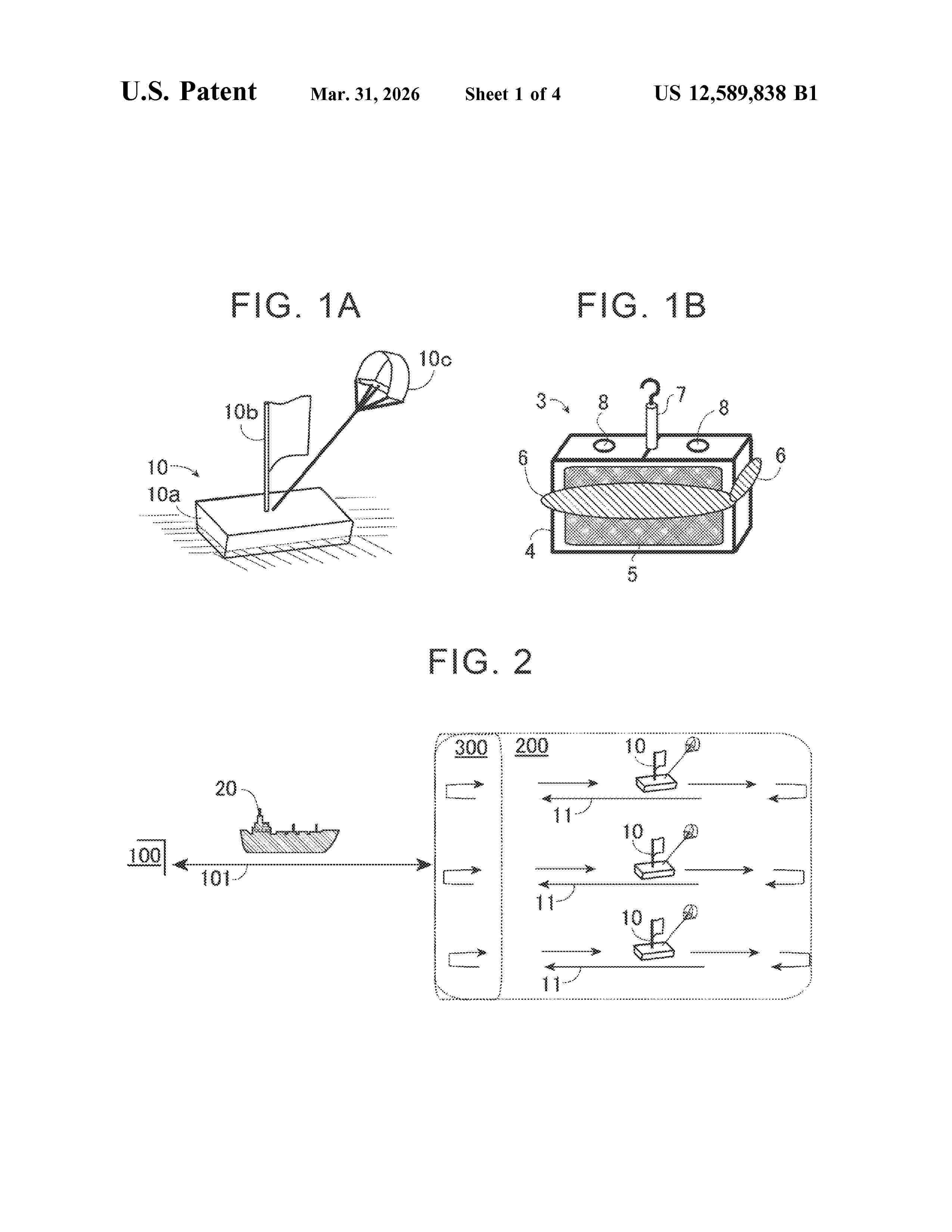
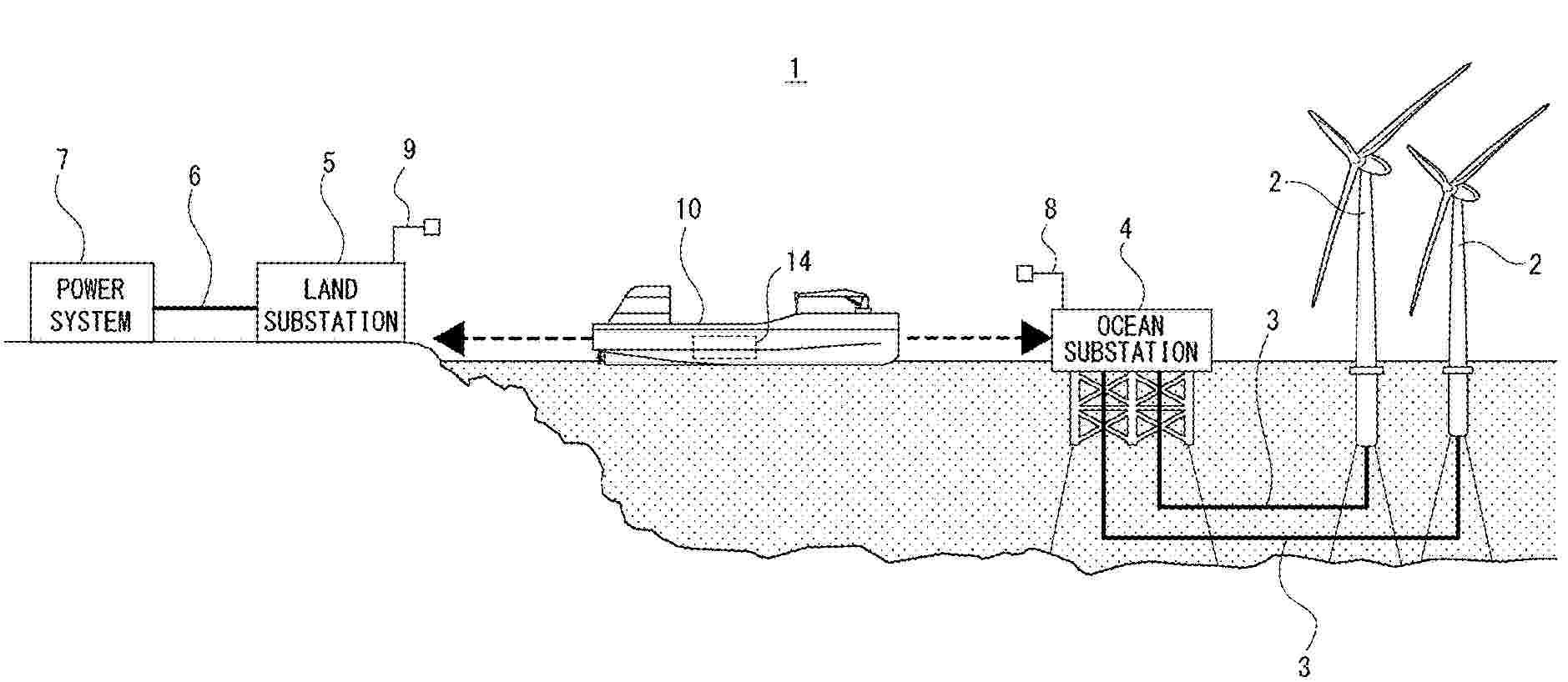
0000 A method of transferring a storage medium on the ocean between a power generation floating body that generates electricity on the ocean and stores energy obtained by the power generation in the storage medium and a transport vessel that transports the storage medium includes a first process of moving the power generation floating body to a predetermined sea area and dropping the first storage medium loaded on the power generation floating body onto the ocean, a second process of moving the transport vessel to a predetermined sea area and dropping the second storage medium loaded on the transport vessel onto the ocean, a third process of recovering the second storage medium dropped from the transport vessel to the ocean to the power generation floating body, and a fourth process of recovering the first storage medium dropped from the power generation floating body onto the transport vessel.
Resumen de: EP4714818A2
A floating wind power generation device may include a power generation unit configured to perform a wind power generation action, and a floating body provided to support the power generation unit, wherein the floating body includes a main column configured to support the power generation unit, a plurality of auxiliary columns provided around the main column, a plurality of connecting members configured to connect the main column and each of the plurality of auxiliary columns, and a plurality of pontoons provided below the plurality of connecting members with respect to the direction of gravity to support a self-weight of the main column and the plurality of auxiliary columns.
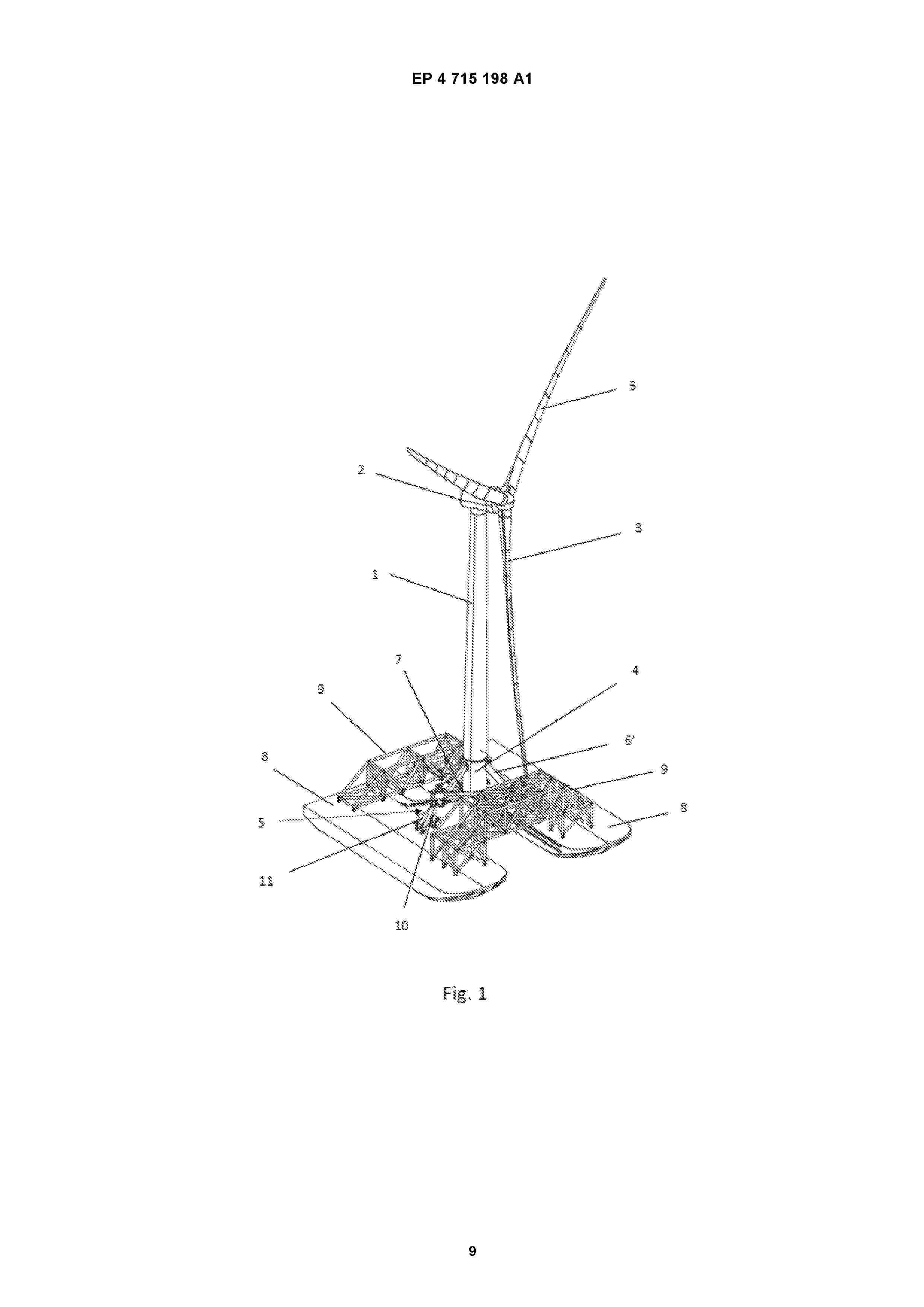
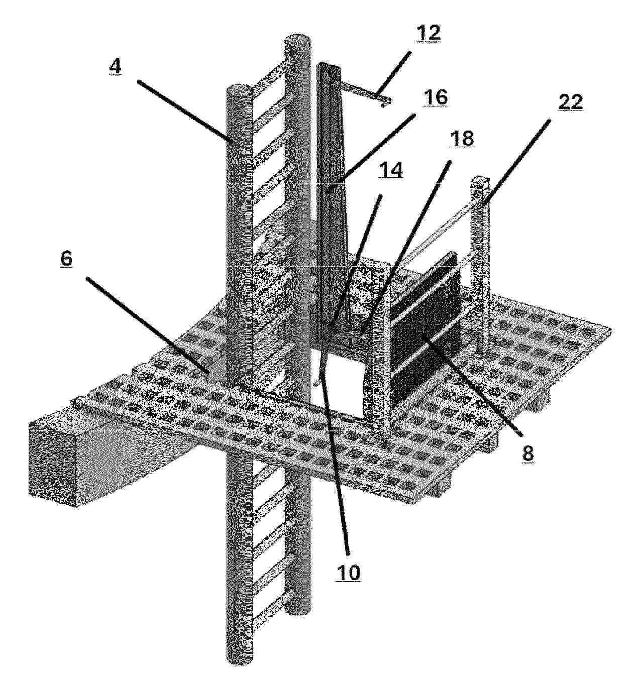
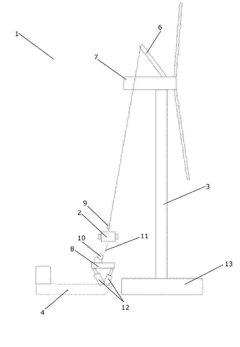
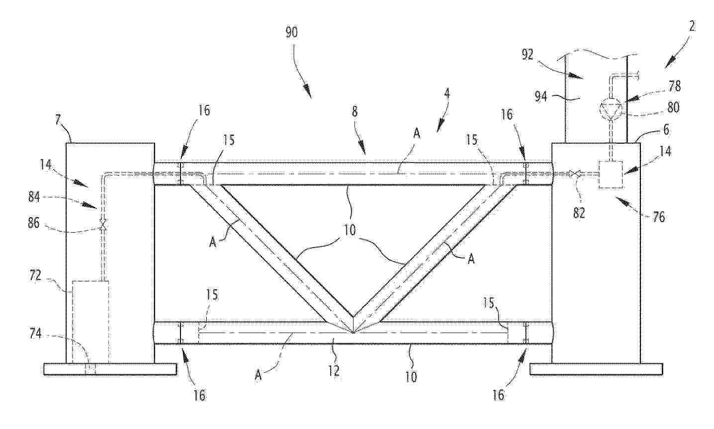
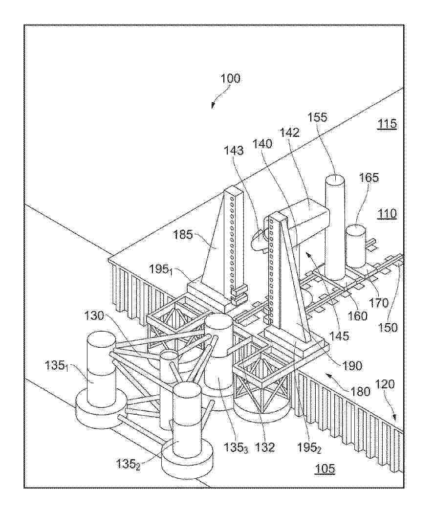
Resumen de: EP4715198A1
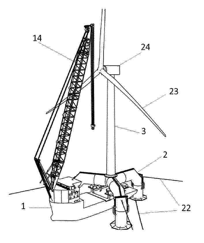
The invention relates to a method for assembling an offshore wind turbine that is separated in two parts that are pre-assembled in a port: a jacket-type lattice structure (15) anchored to the seabed with a foundation and a superstructure that includes a transition piece (4), a tower (1), a nacelle (2) and blades (3) transported floating in a vertical position. Tripod supports (5) are anchored on the double-pontoon vessel (8) that is braced (9) at the bow and stern, and a triangle (7) supporting the superstructure is disposed in the tripod supports.During the transport phase, the hydraulics (14) included in the inside the tripod supports (5) are retracted, the movable parts are connected by a bolted joint, and the vessel (8) is ballasted. Once the positioning of the jacked (15) has been carried out, both parts are fastened by moorings (16), movement limiters (18) and impact limiters (18'), the load is transferred with the lowering of the hydraulic cylinders (14), and contact occurs between the upper portion of the jacket (15) and the receiver of the passive coupling system (23). Once the assembly is complete, the passive coupling system (23) arranged on the transition piece is recovered, the triangle (7) is dismantled, and the bracing (9) of the stern is folded down or removed to release the vessel (8).
Resumen de: EP4714815A1
A hatch assembly is provided, the assembly comprising a hatch lid connected via a connecting bar to an actuation means, such that opening and closing of the hatch lid by a user can be actuated at a location different from that of the hatch lid.
Resumen de: EP4714817A2
A method and a system (1) for controlling transfer of a suspended load (2) between an offshore wind turbine (3) and a floating vessel (4) are disclosed. Movements, relative to the floating vessel (4), of a load (2) suspended in a hoisting mechanism (6, 15) and/or of a hooking part (9) of the hoisting mechanism (6, 15), are detected. A position and/or inclination of a landing platform (8) arranged on the floating vessel (4) is adjusted, based on the detected movements, in order to compensate for relative movements between the floating vessel (4) and the suspended load (2) and/or the hooking part (9), thereby synchronizing movements of the landing platform (4) to movements of the suspended load (2) and/or the hooking part (9), while moving the suspended load (2) and/or the hooking part (9) towards the adjustable landing platform (8). The step of detecting movements of a load (2) suspended in the hoisting mechanism (6, 15) and/or of a hooking part (9) of the hoisting mechanism (6, 15) comprises detecting the movements by means of one or more sensors arranged on the suspended load (2) and/or the hooking part (9). A step of communicating sensor readings from the one or more sensors to a control unit for controlling the adjustable landing platform (8) is further comprised
Resumen de: WO2024236128A1
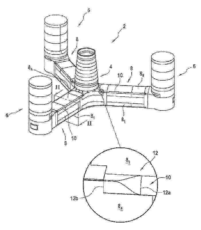
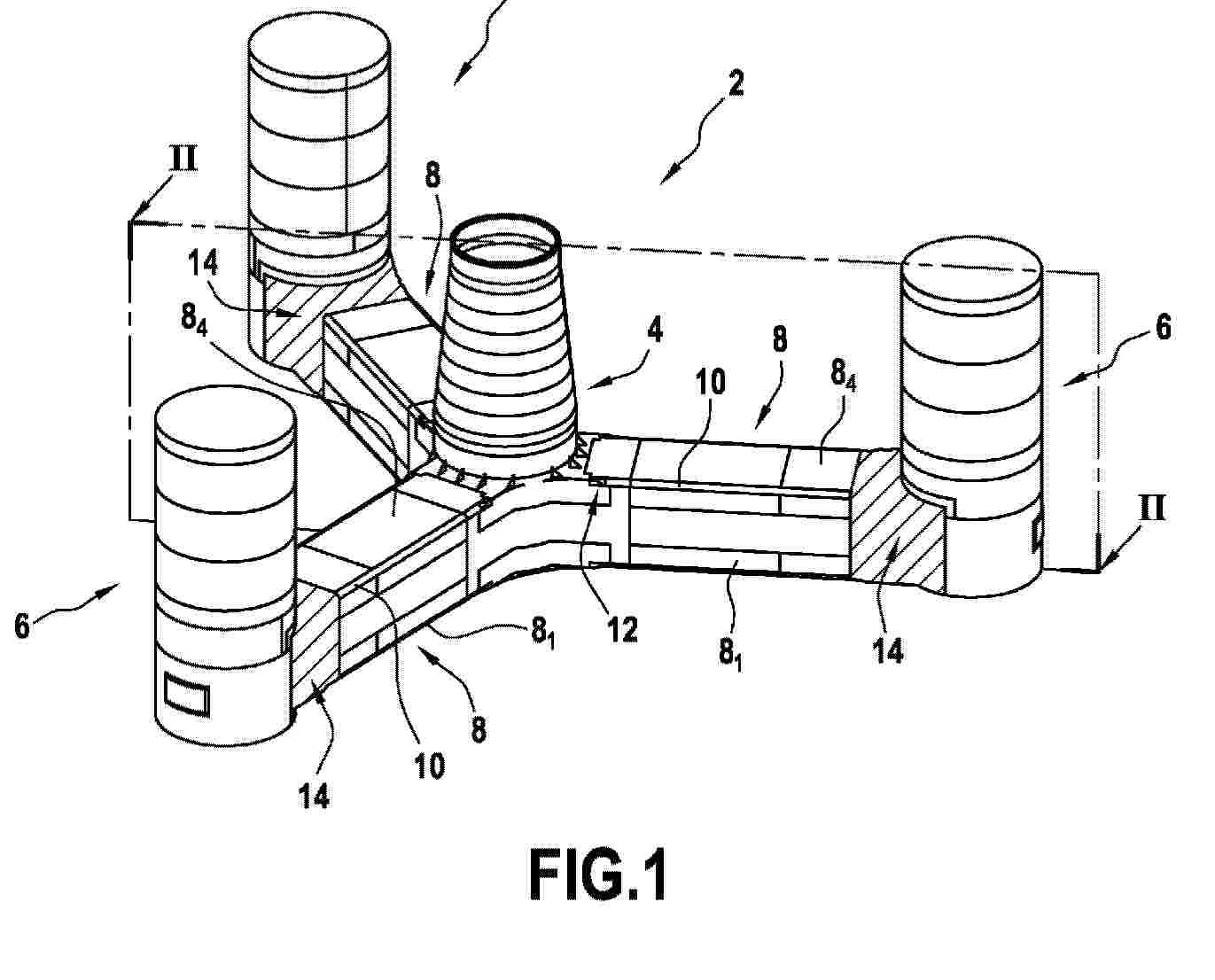
The floating offshore platform (2) comprises a support structure (4) having a beam (8) configured for extending between first and second structural elements (6, 7), the beam (8) being formed of several tubes (10) connected together and comprising a tank (12) delimited within at least two tubes (10) connected such that the individual internal volumes of said at least two tubes (10) are in fluid communication, and at least three connections (16) each configured for mechanically connecting an end of one tube (10) of the beam (8) to one of the first and second structural elements (7), wherein each connection (16) with the first structural element (6) is a bolted flange connection (16) and/or each connection (16) with the second structural element (7) is a bolted flange connection (16).
Resumen de: WO2024236172A1
Structure assembly comprising a beam with an integrated tank delimited in two tubes of the beam The structural assembly comprises a beam (8) configured for extending between first and second structural elements (6, 7) of a support structure (4), the beam (8) being formed of several tubes (10) with a tank (12) delimited within at least two tubes (10) of the beam (8), said at least two tubes (10) being connected such that the individual internal volumes of said at least two tubes (10) are in fluid communication, and at least three connections (16), each connection (16) being configured for mechanically connecting an end of one tube (10) of the beam (8) to one of the first and second structural elements (6, 7), wherein each connection (16) with the first structural element (6) is a bolted flange connection and/or each connection (16) with the second structural element (7) is a bolted flange connection.
Resumen de: WO2024236111A1
A support structure (4) of the floating offshore platform comprises a beam (8) formed of one or several tubes (10) with a tank (12) delimited inside one or several tubes (10) of the beam (8), and a least one bolted flange connection (16) connecting an end of one tube (10) of the beam (8) to another structural element (6) of the support structure (4), each bolted flange connection (16) comprising a first flange (20) and a second flange (22) bolted together with bolts (24), wherein at least one bolted flange connection (16) is sealed with a sealing assembly (32) comprising at least one sealing member (34) configured for sealing the bolted flange connection (16).
Resumen de: WO2026059486A1
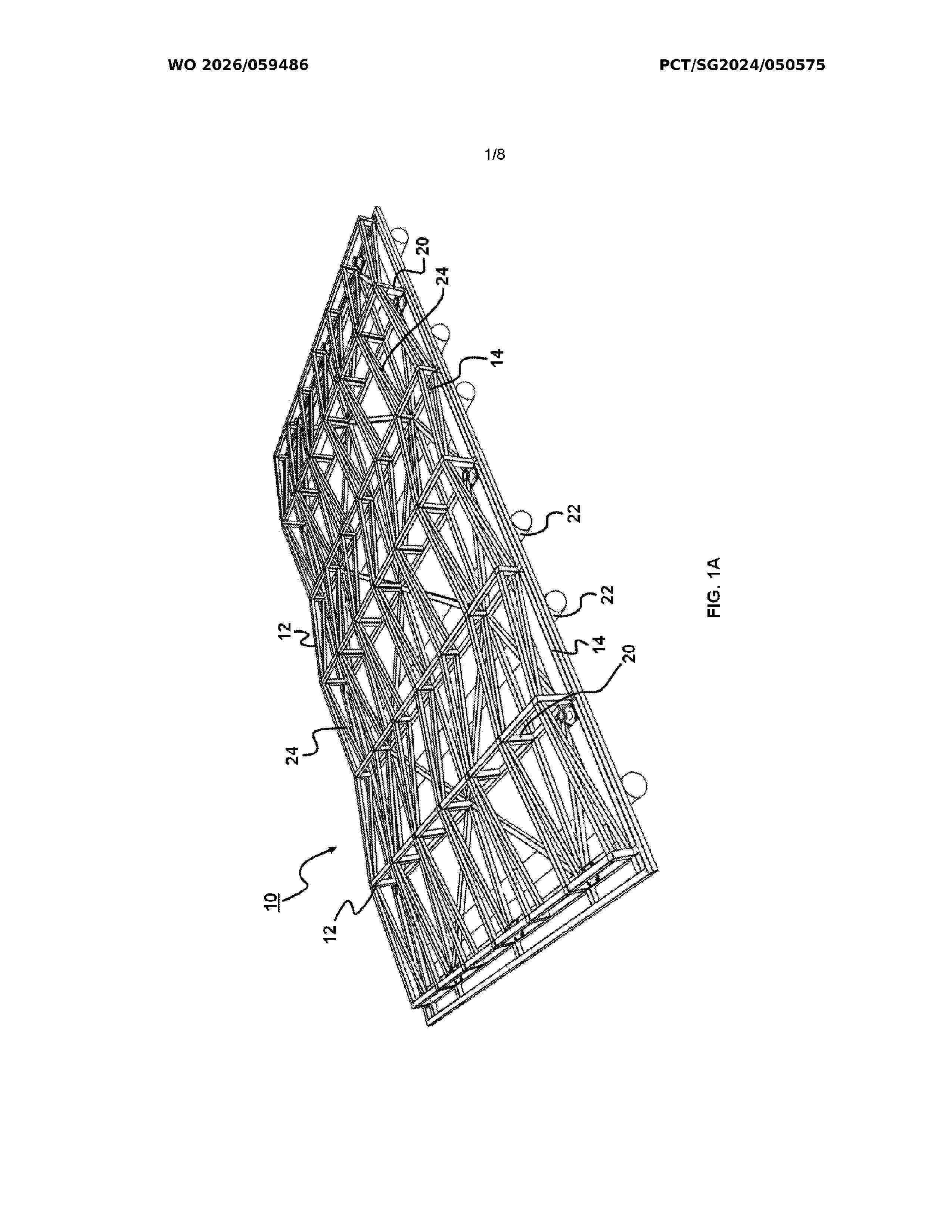
An offshore platform (10) for energy farming is provided. The offshore platform (10) includes a plurality of first beams (12) arranged to receive a plurality of solar panels, the first beams (12) defining a first layer (16), a plurality of second beams (14) arranged 5 to define a second layer (18), and a plurality of posts (20) separating the first and second layers (16, 18). A plurality of hollow pipes (22) is attached to a base of the second layer (18), the hollow pipes (22) extending across the second layer (18).
Resumen de: WO2026057134A1
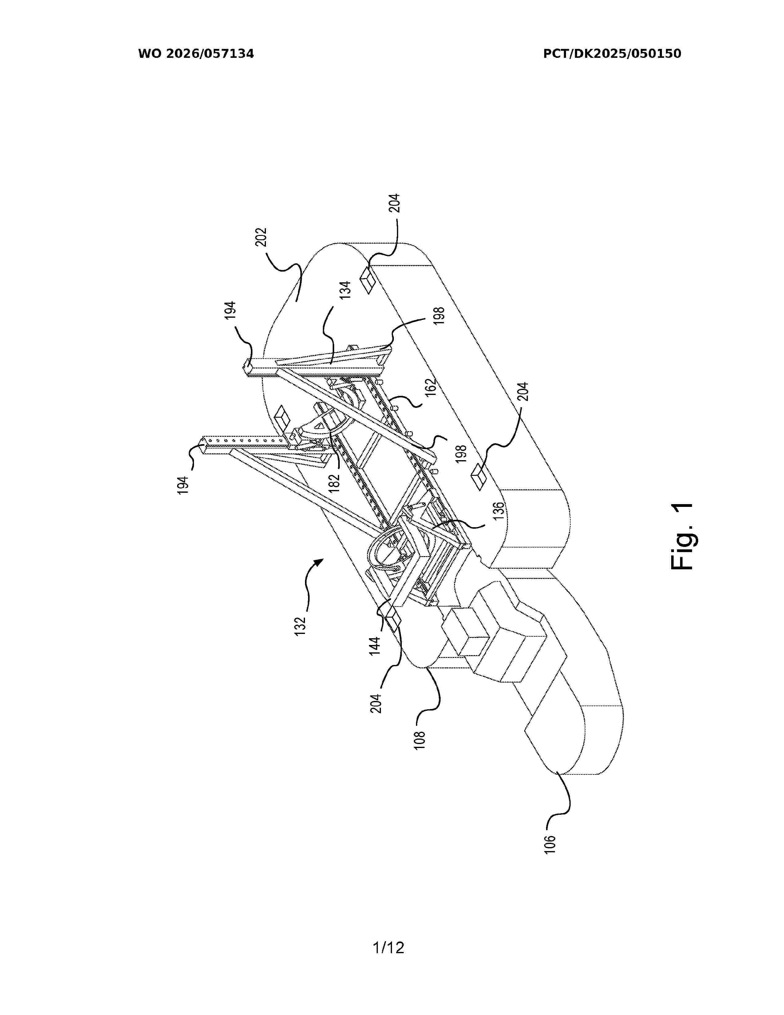
An offshore installation system (100) for handling a monopile comprises a monopile transportation vessel (102) configured to transport the monopile in a horizontal position. A monopile handling mechanism (132) is mounted on the transportation vessel (102) and is configured to secure the monopile during transportation and move it to an inclined position. The system also includes an offshore installation vessel with a hull (122) and a plurality of moveable legs (126), wherein the hull is positioned out of the water when the moveable legs engage the seafloor. A push down stabilising mechanism (130) is mounted on the offshore installation vessel and is configured to apply a downward force on the monopile transportation vessel to increase its buoyancy force when positioned underneath the hull, stabilising the monopile transportation vessel and the inclined monopile with respect to the offshore installation vessel.
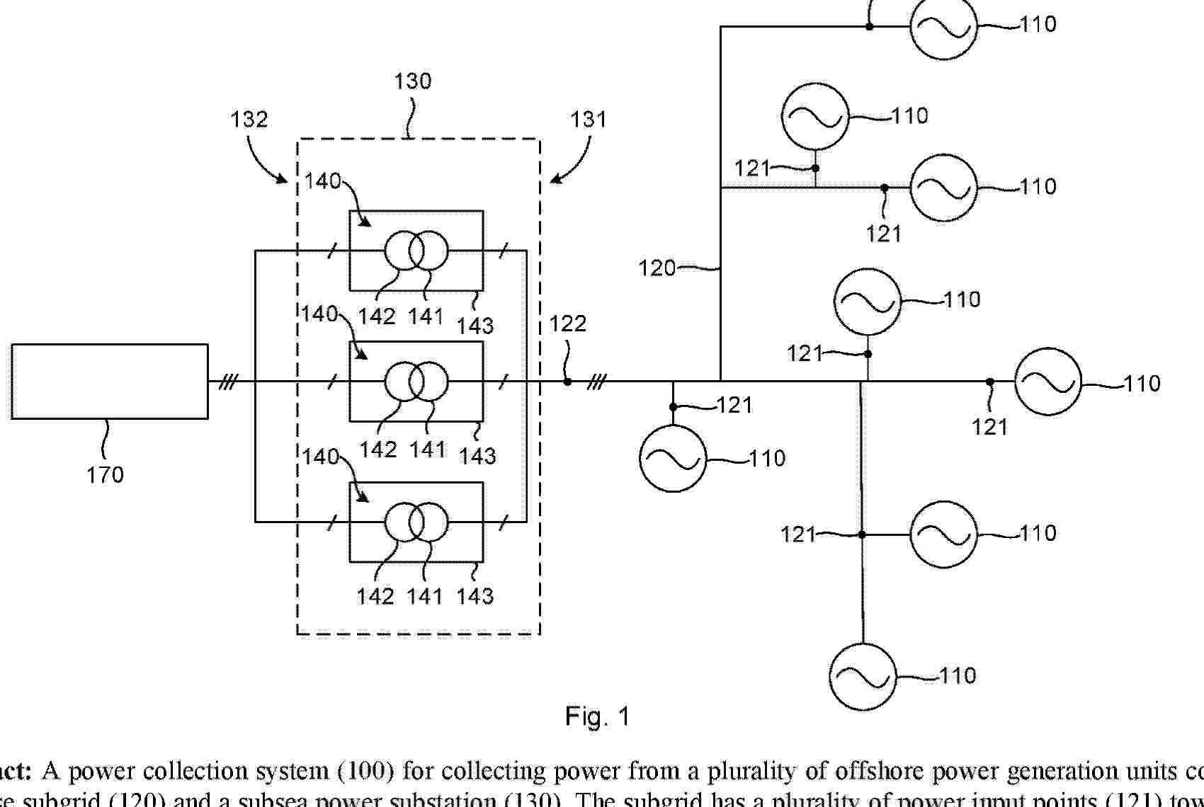
Resumen de: AU2024330912A1
A power collection system (100) for collecting power from a plurality of offshore power generation units comprises a three-phase subgrid (120) and a subsea power substation (130). The subgrid has a plurality of power input points (121) towards the power generation units and a shared three-phase power output point (122). The power substation (130) is connected to the power output point, and its secondary side (132) is arranged to be connected to a power consumer (170). The power substation shall comprise three one-phase transformers (140), which are contained in respective housings (143), wherein each housing is arranged to rest on the seabed and to be liftable to the sea surface separately from the other housings. Each phase of the power output point is connected to a primary side (141) of a corresponding one of the one-phase transformers.
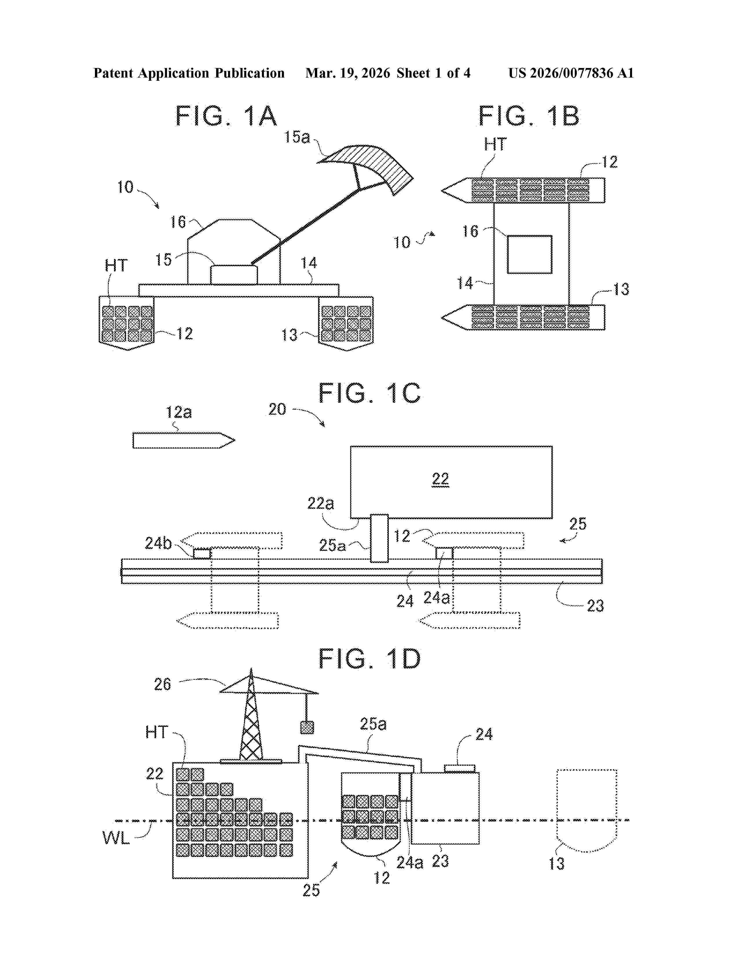
Resumen de: US20260077836A1
In a method for transferring a storage medium of power generation energy loaded by a power generation float to a collection base, a power generation float is connected to both sides of a deck part, a power generation float is moved to a collection base, a deck part straddles a long bank projecting on a water surface along a water channel through which a hull can pass along a quay wall of a collection base, a power generation float is anchored in a state where one of the hulls enters a water channel, a hull on at least one side of the deck part is separated from the deck part, and a storage medium capable of storing energy is connected on a side where the hull of the deck part is separated, and the float leaves with the hulls connected to both sides of the deck part.
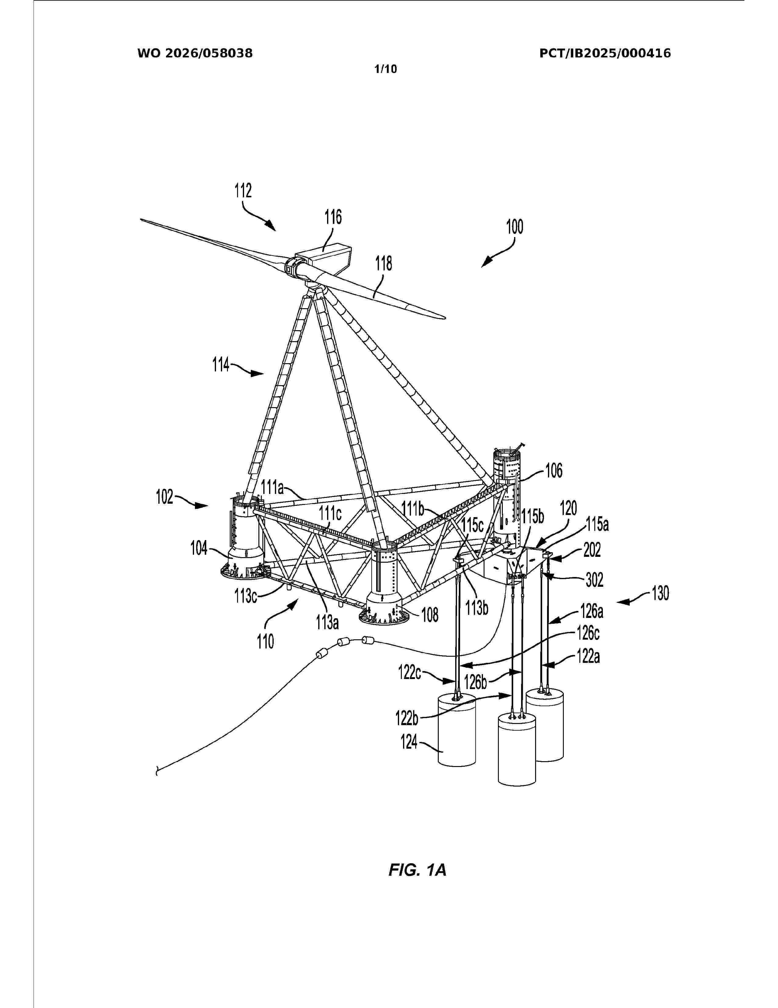
Resumen de: WO2026058038A1
A tensioned leg floating platform mooring system and related methods may be used to secure the position of a floating platform. For example, the floating platform mooring system may include at least three fixed-length mooring lines coupled at different locations between a floating platform and one of one or more mooring piles. Additionally, the tensioned leg floating platform mooring system can include an adjustable-length mooring line coupled between the floating platform and one of the one or more mooring piles. The floating platform mooring system may further include a mooring line tension device coupled to the adjustable-length mooring line. The mooring line tension device may adjust a tension of the adjustable-length mooring line by adjusting a length of the adjustable-length mooring line in situ.
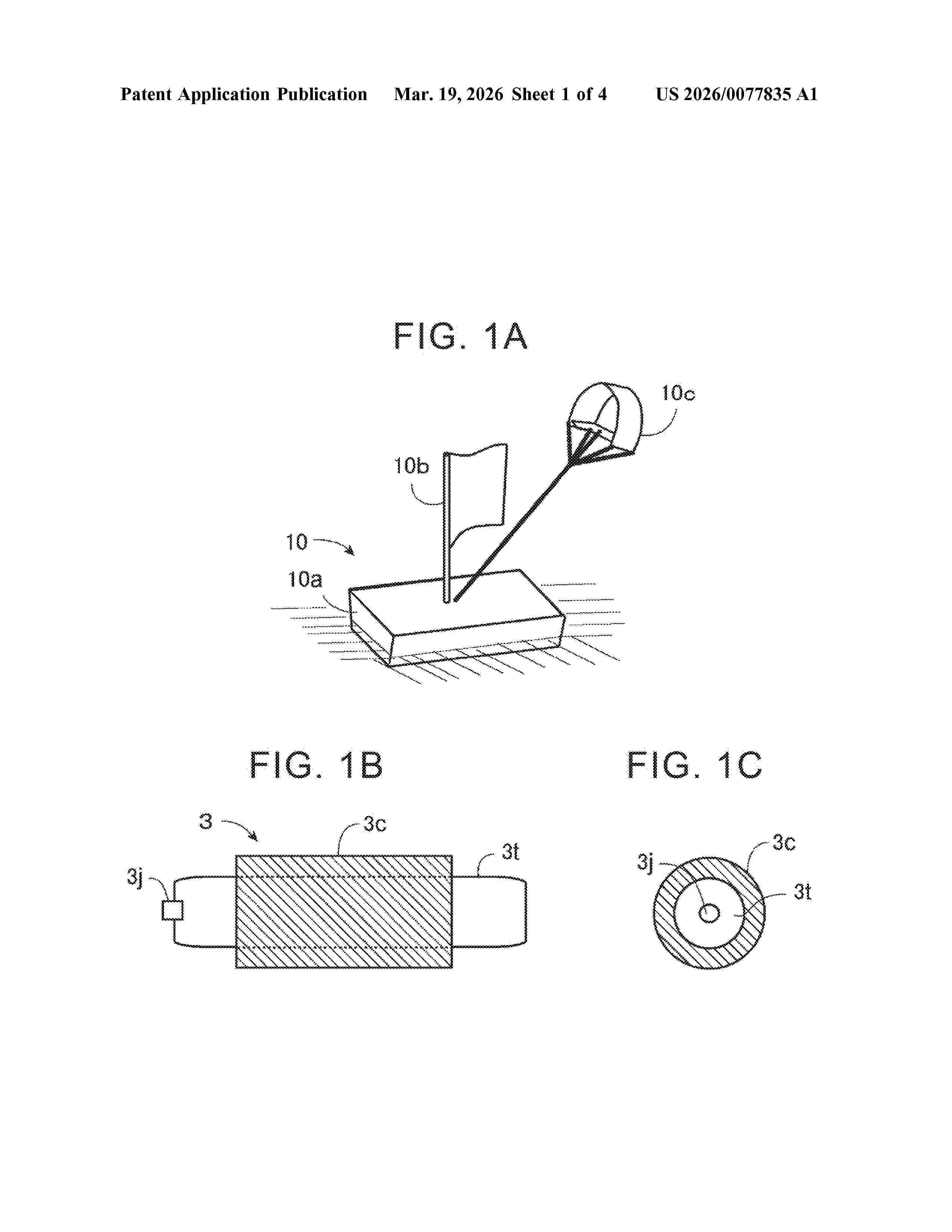
Resumen de: US20260077835A1
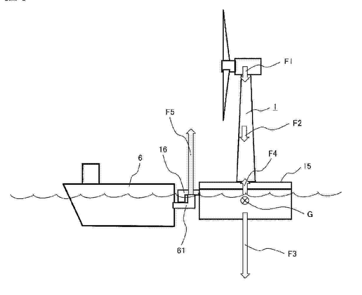
A method of transferring a storage medium loaded on a power generation float from a float that generates electricity on the ocean to a transport vessel on the ocean includes a first process of fixing the power generation float to the transport vessel so that a height of a loading place of the storage medium of the power generation float is higher than a height of a storage place of the storage medium of the transport vessel, a second process of forming a first path in which the storage medium can move between the loading place of the storage medium of the power generation float and the storage place of the storage medium of the transport vessel, and a third process of moving the storage medium from the loading place of the power generation float to the storage place of the transport vessel by gravity through the first path.
Resumen de: EP4711258A1
A floating quay includes a deck relocatable in a body of water adjacent a stationary quay to receive one or more floating units. The deck includes a gradual slope from an elevation of a surface of the stationary quay to a submerged position below a water level of a water surface of the body of water. The floating quay further includes an elevator system positionable to raise and lower at least a portion the deck to receive the one or more floating units from the stationary quay and to deploy the one or more floating units into the body of water using the gradual slope of the deck.
Resumen de: EP4711257A1
A tensioned leg floating platform mooring system and related methods may be used to secure the position of a floating platform. For example, the floating platform mooring system may include at least three fixed-length mooring lines coupled at different locations between a floating platform and one of one or more mooring piles. Additionally, the tensioned leg floating platform mooring system can include an adjustable-length mooring line coupled between the floating platform and one of the one or more mooring piles. The floating platform mooring system may further include a mooring line tension device coupled to the adjustable-length mooring line. The mooring line tension device may adjust a tension of the adjustable-length mooring line by adjusting a length of the adjustable-length mooring line in situ.
Resumen de: US20260070634A1
The method for counterbalancing the mean inclination of a Floating Offshore Wind Turbine (FOWT) platform is designed to be simple, efficient, and highly responsive. It employs short-distance piping to enable swift and effective pump-in and pump-out operations within the same column, allowing for precise and independent control of ballast operation. This strategy is not only cost-efficient but also supports remote operation, facilitating rapid adjustments for both normal and abnormal conditions. Furthermore, the method incorporates redundancy in the counterbalancing systems, significantly boosting the overall reliability and ensuring consistent and effective ballast management for the platform.
Resumen de: AU2024351711A1
The invention relates to a method for the active and individualised ballasting of a semi-submersible float (2) for an offshore wind turbine, the float comprising at least four columns, including a central column (4) and three outer columns (6), which are connected to the central column by lower arms forming pontoons (8), wherein the method comprises, for each pontoon, the individualised and controlled displacement of a ballast fluid between at least two separate sealed compartments (14, 16) located inside an assembly formed by the pontoon and the associated outer column, so as to modify the inclination of the float. The invention also relates to a semi-submersible float for an offshore wind turbine with active and individualised ballasting.
Resumen de: DE102024136925A1
Schwimmende Windenergieanlage (10) mit einem schwimmenden Fundament, das eine Mehrzahl von sich von einem Zentralelement (20) erstreckenden Armen (30) aufweist, einem auf dem Zentralelement (20) des schwimmenden Fundaments angeordneten Turm (40) mit wenigstens einer auf dem Turm (40) angeordneten mit diesem drehfest verbundenen, einen Rotor aufweisenden Energiewandlungseinheit, und einem das Fundament mit der wenigstens einen Energiewandlungseinheit verbindendem Seilsystem (50) zur Einleitung der auf den Turm (40) und die wenigstens eine Energiewandlungseinheit wirkenden Schubkräfte in das Fundament, wobei das Seilsystem (50) Vorspannungen aufweist, deren Beträge jeweils größer als im Betrieb der Windenergieanlage zu erwartende, der jeweiligen Vorspannung entgegenwirkende Lasten sind, dadurch gekennzeichnet, dass der Turm (40) in einem am Zentralelement (20) angeordneten axialen Pendelgleitlager (60) gelagert ist.
Resumen de: AU2024353216A1
The invention relates to a method for the active and centralised ballasting of a semi-submersible float (2) for an offshore wind turbine, the float comprising at least four columns, including a central column (4) and three outer columns (6), which are connected to the central column by lower arms forming pontoons (8), wherein the method comprises the controlled and centralised displacement of a ballast fluid between sealed compartments (14) formed inside each pontoon (8), so as to modify the inclination thereof. The invention also relates to a semi-submersible float for an offshore wind turbine with active and centralised ballasting.
Resumen de: AU2024263697A1
The invention relates to a mooring arrangement for mooring a floating unit to the seabed, the mooring arrangement comprises multiple mooring clusters each connectable to a floating unit and an anchor adapted for the seabed, wherein at least one mooring cluster comprises at least two mooring lines.
Resumen de: EP4707152A1
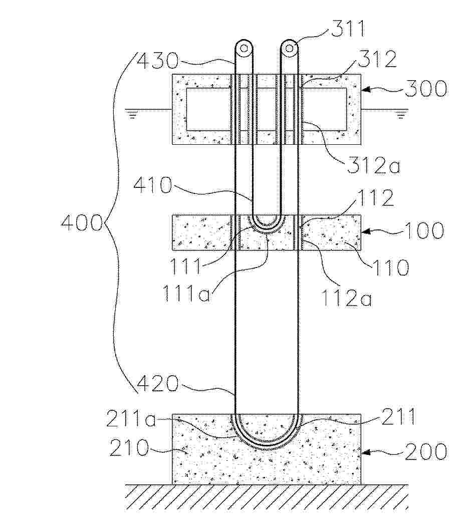
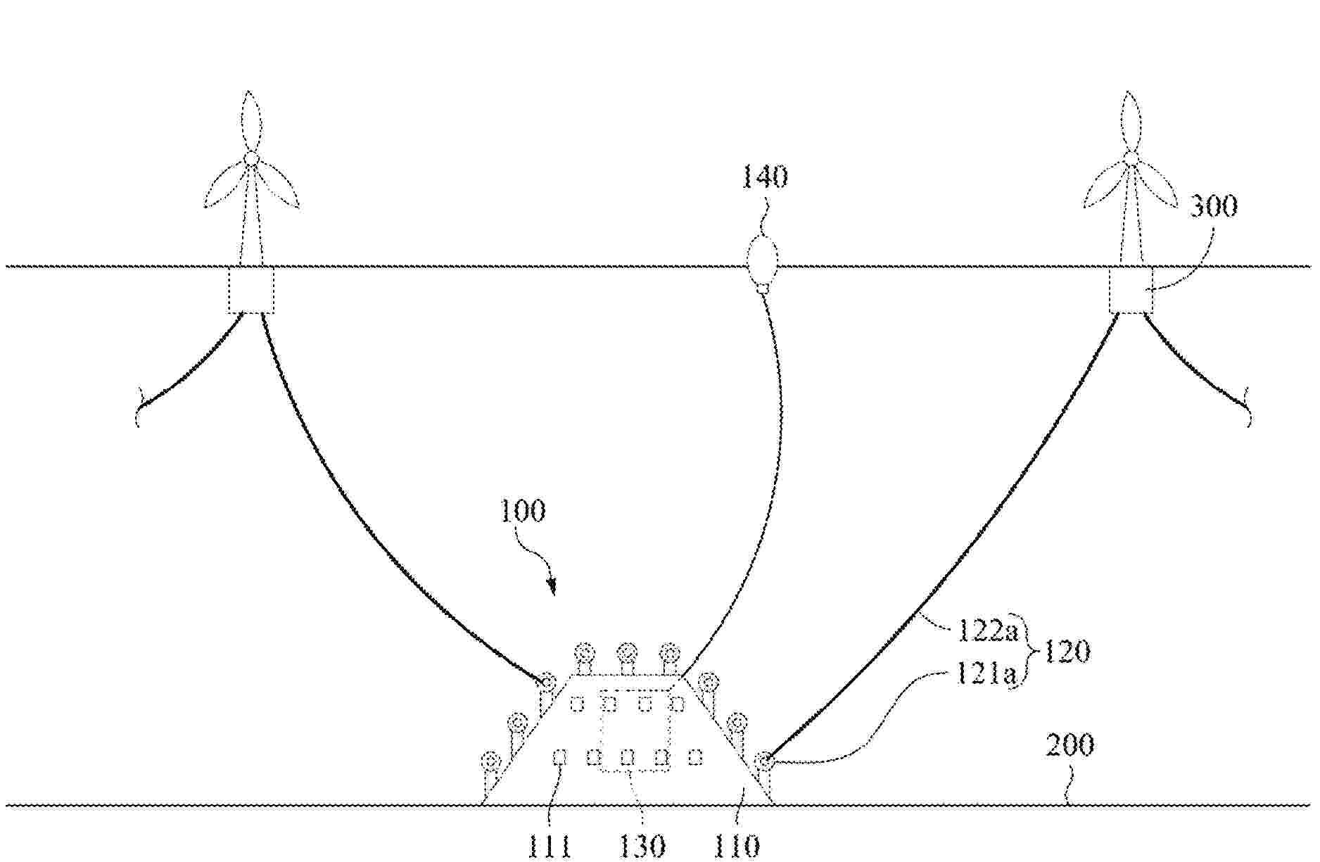
Proposed is a mooring system, including a floating unit for floating on the sea surface, a mooring anchor installed on the seabed, a weight unit positioned underwater between the floating unit and the mooring anchor, a plurality of mooring cables each having a closed curve shape for mooring the floating unit, wherein each mooring cable includes a first portion whose middle lower part is caught in a mooring-cable catching part of the weight unit, a second portion which passes through a vertical penetration passage of the weight unit and whose middle lower part is caught in a mooring-cable catching part of the mooring anchor, and a third portion which passes through a vertical penetration passage of the floating unit and is connected to the first portion and the second portion and whose middle upper part is caught in a mooring-cable catching part of the floating unit provided in the floating unit.
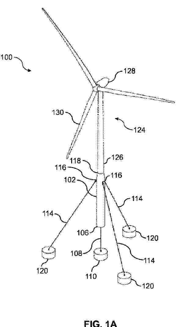
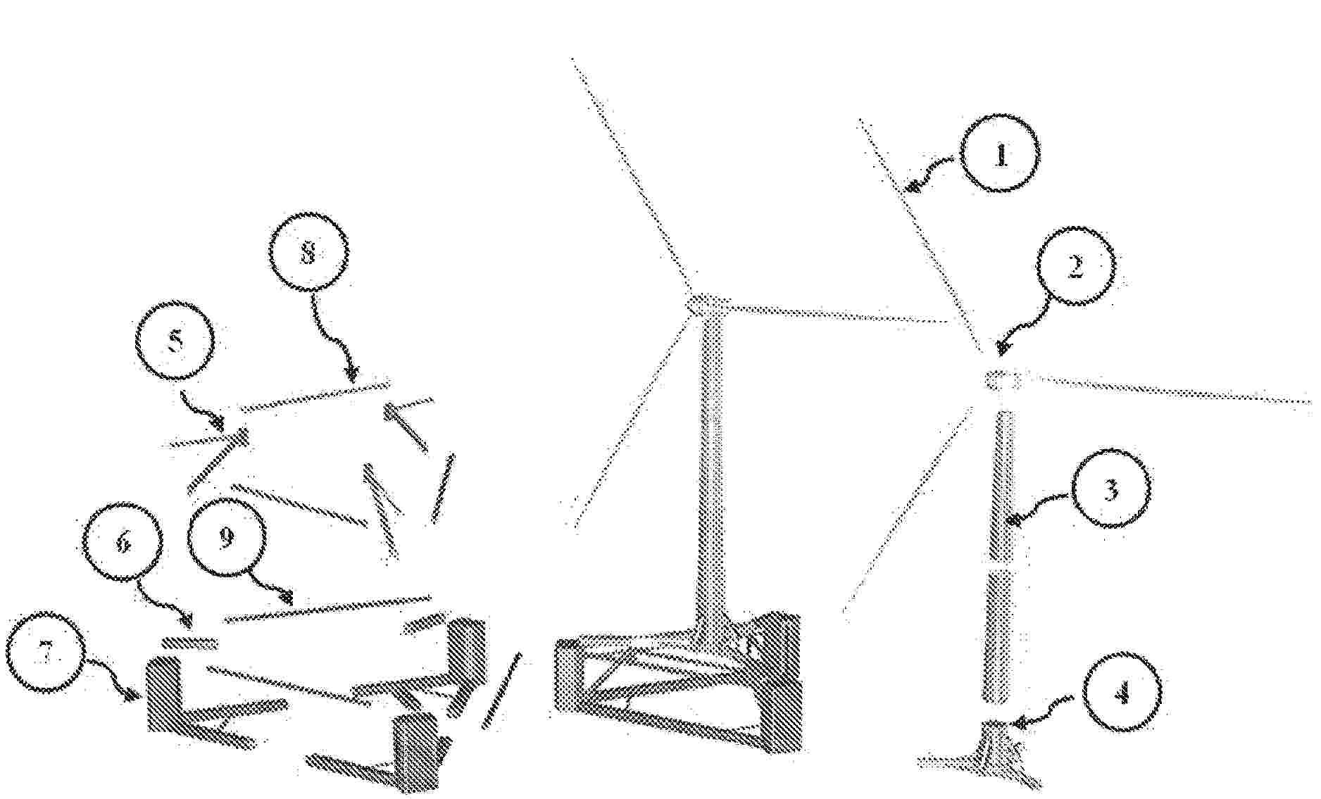
Resumen de: BE1032839A1
L'invention divulgue un procédé de contrôle d'un système d'énergie éolienne en mer, se rapportant au domaine technique du contrôle de l'énergie éolienne en mer. Ledit système d'énergie éolienne en mer comprend un groupe éolien, un convertisseur, des capteurs de vibration et de contrainte ainsi qu'un contrôleur, et vise à résoudre le problème technique consistant à efficacement inhiber les charges structurelles clés tout en garantissant la sortie de puissance. Les points clés de sa solution technique sont les suivants: obtenir une séquence de vitesse de vent de prévision à l'avant par le biais d'un lidar de nacelle, tout en collectant en temps réel les données de charges de la tour et des pales; construire un modèle d'espace d'état paramétré, et utiliser l'algorithme de filtre de Kalman sans trace pour réaliser l'identification en ligne et l'estimation d'état des paramètres aérodynamiques et de la dynamique non modélisée; dans chaque période de contrôle, avec le suivi de puissance et l'inhibition de charges comme objectifs multiobjectifs, résoudre le problème de contrôle optimal à horizon fini sur la base du modèle mis à jour et de la séquence de vitesse de vent de prévision; enfin, analyser et exécuter la commande incrémentale optimale de l'angle de calage et la commande incrémentale optimale du couple du générateur. Ce procédé est principalement utilisé pour améliorer la durée de fonctionnement et la stabilité des group
Resumen de: WO2024246151A1
A buoyant offshore renewable energy system mounting platform is provided for use in supporting a renewable energy system in a body of water. The platform comprises a buoyant spar having a top end and a bottom end, the spar arranged to support a renewable energy system thereon; and a plurality of mooring lines arranged to tether the spar to a bed of a body of water such that the buoyant spar is positioned in the body of water at an operating depth. The plurality of mooring lines comprise: one or more first mooring lines affixed to a bottom end of the spar, the bottom end distal to the top end, and arranged to engage the bed of the body of water; and at least three further mooring lines, a first end of each of the further mooring lines being in communication with the spar between the top end and the bottom end thereof, and a second end of each further mooring line being arranged to engage the bed of the body of water such that said further mooring line is oriented diagonally relative to the spar at the operating depth; wherein at the operating depth, the first end of the spar is positioned above a surface of the body of water and the second end is positioned below the surface of the body of water. The described platform aims to provide a simple and stable offshore renewable energy system mounting solution having a simpler manufacture, assembly and deployment procedure along with easier ongoing access for deployment and maintenance vessels to minimise damage during deployment an
Resumen de: US20260063108A1
A floating structure foundation for a wind turbine features several improvements, including a transition assembly that supports the wind turbine generator (WTG) and tower centrally, transferring loads to primary structural components to maximize efficiency. Its highly modular design allows for flexible construction and scalability, with each component built independently for easier adaptation to different project requirements and site conditions. This modularity supports efficient dry transport, enabling multiple modules to be shipped simultaneously on various vessels. The foundation offers a simplified design with accelerated construction, rapid assembly, and installation.
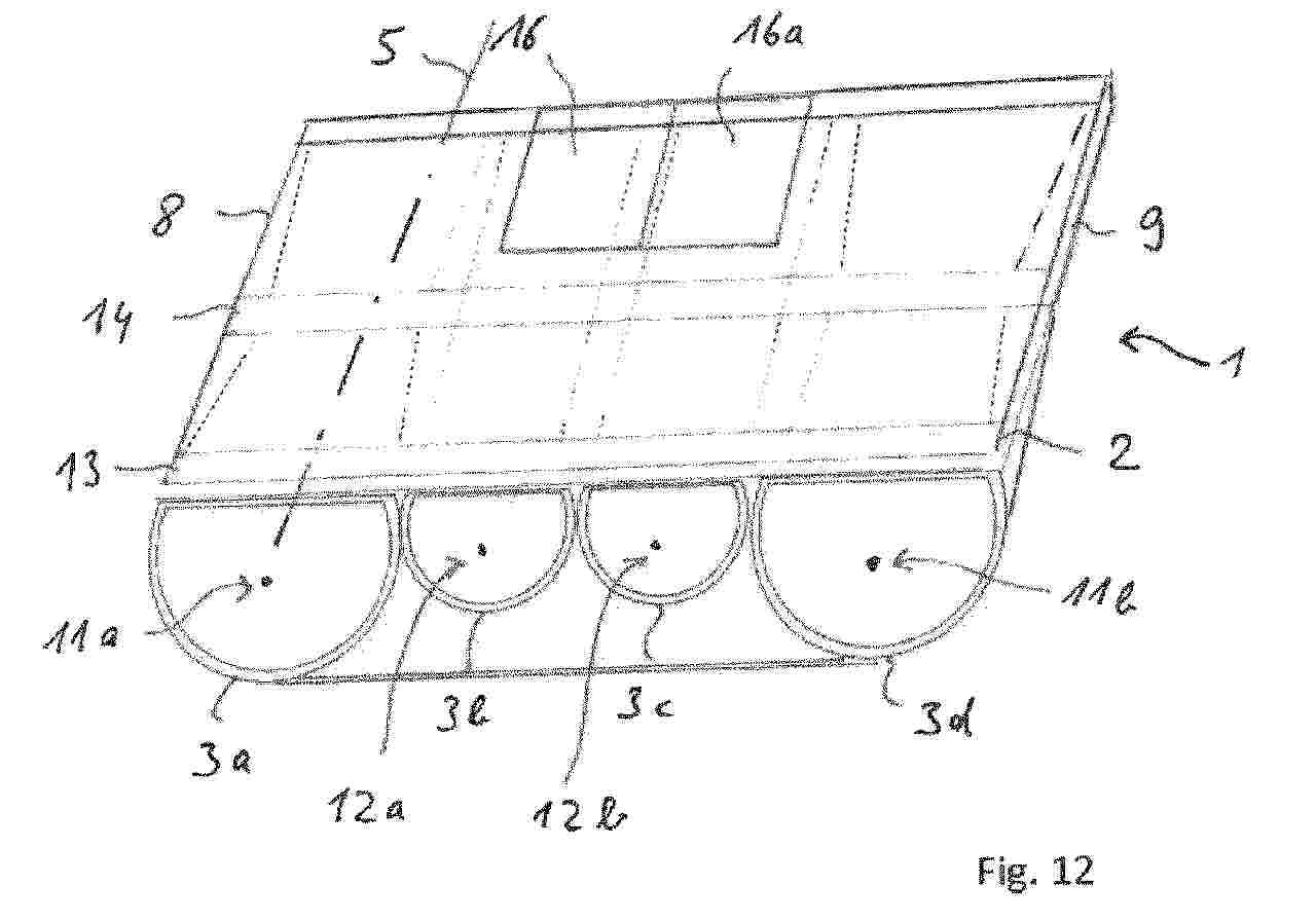
Resumen de: WO2026047105A1
The invention relates to a floating functional unit, in particular a floating platform (1) or a watercraft, comprising a deck structure (2) and one or more buoyancy bodies (3a, 3b, 3c, 3d), one or more of the buoyancy bodies each comprising a rotor blade (4) or a part, in particular a longitudinal portion, of a rotor blade of a wind turbine. The invention further relates to such a buoyancy body and to a method for the production thereof from a rotor blade.
Resumen de: WO2026047260A1
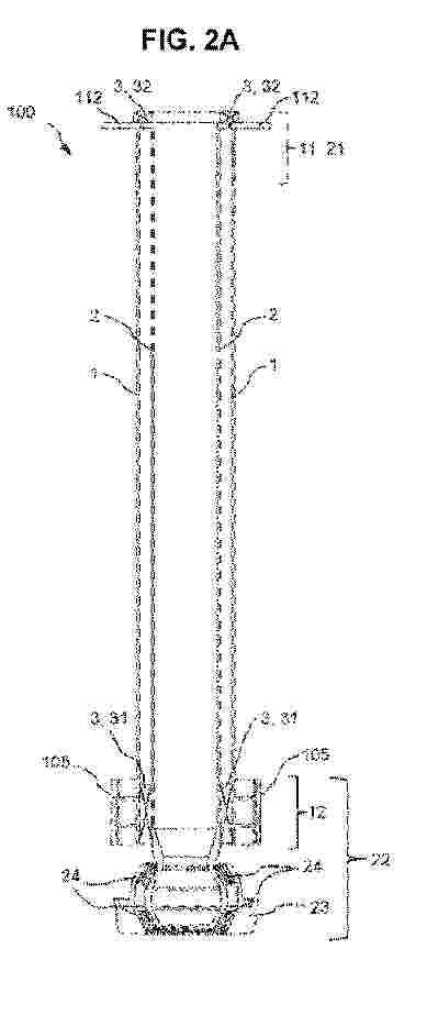
The present invention relates to a floating wind turbine generator (WTG) foundation for a floating WTG system, the floating WTG foundation comprising: a floater having a generally cylindrical shape, wherein the floater defines a vertical axis, the floater comprising ballast at a lower end thereof, an upper projection extending upward from the floater, the upper projection having a smaller cross-section than the floater, at least three anchors which are connected to the seabed, at least three tendon assemblies, each tendon assembly extending between one of the anchors and a respective mounting position on the floater.
Resumen de: WO2026047092A1
A turret connecting module (100) for being selectively inserted in an operating position (O) within a weathervaning floating offshore structure (200) of a wind turbine (202) for connecting said weathervaning floating offshore structure (200) to a pre-laid mooring system (300), the turret connecting module (100) comprising: an external trunk element (1) configured to be attached to the weathervaning floating offshore structure (200); an internal shaft element (2) configured to be arranged within the external trunk element (1), and comprising a base portion (22) configured to be coupled to the pre-laid mooring system (300); and a bearing system (3) comprising at least one bearing (31, 32) configured to connect the external trunk element (1) to the internal shaft element (2) such that the external trunk element (1) is allowed to weathervane together with the weathervaning floating offshore structure (200) relative to the internal shaft element (2) and the prelaid mooring system (300).
Resumen de: AU2024327326A1
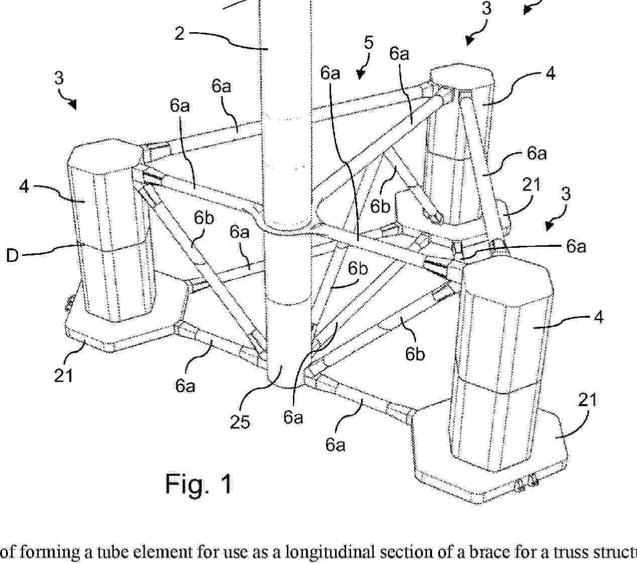
Method of forming a tube element for use as a longitudinal section of a brace for a truss structure of a floatable offshore support structure for a wind turbine, comprising: providing four elongate flat steel plates each extending along a longitudinal direction and having two opposite lateral edges; deforming each plate such that, along the longitudinal direction, a transverse shape of the plate smoothly transitions between a rectilinear shape and an arcuate shape; and forming the tube element by interconnecting the four deformed plates along their lateral edges. The interconnected plates each form a respective circumferential section of the tube element, wherein along the longitudinal direction, a transverse shape of the tube element smoothly transitions from a circular shape to a rectangular shape. The tube element may connect a cylindrical further tube element of the brace with a further part of the floatable offshore support structure.
Resumen de: US20260063101A1
A wave energy-based reef sustainable device integrated with an offshore wind turbine is provided. The wave energy-based reef sustainable device integrated with an offshore wind turbine can be put into a seabed, is configured to connect with a floating wind turbine, and includes a base is configured as a fish reef, an anchoring device configured to connect with the floating wind turbine, and includes plural rings with a luminous coating and at least one mooring system or cable with a luminous layer. The rings swing and/or rotate due to the pull of the floating wind turbine and present a flashing effect to attract fish. The mooring system or cable with the luminous layer provides a warning effect, a lighting device configured to emit light to attract fish, and a green energy device configured to convert a green energy into an electrical energy, which is provided to the lighting device.
Resumen de: CN121001923A
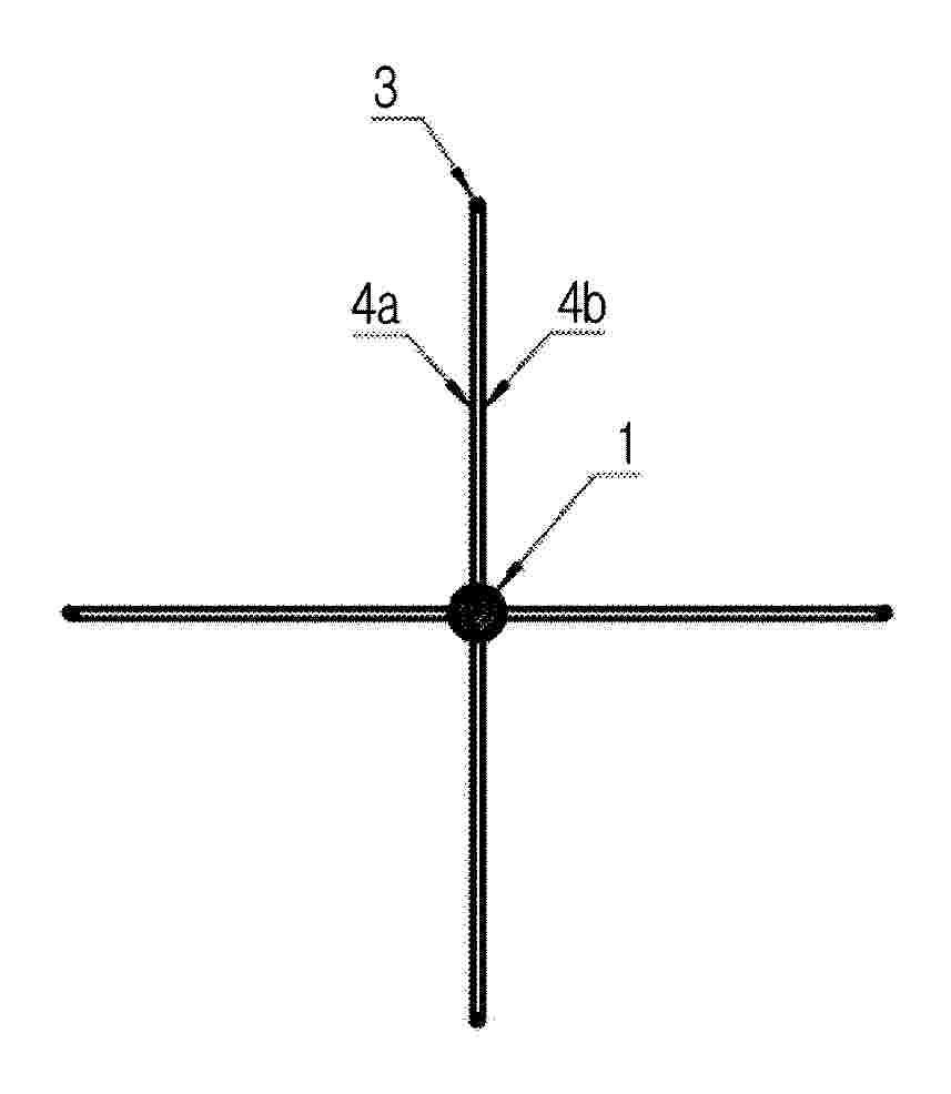
The invention relates to a floating platform (2), the arrangement of anchoring ribs (17, 18) of which makes it possible to improve stability, in particular for a platform of a wind turbine (2). The invention also relates to a method of assembling such a platform and a wind turbine thereof, and to a method of anchoring such a platform at sea.
Resumen de: WO2026042417A1
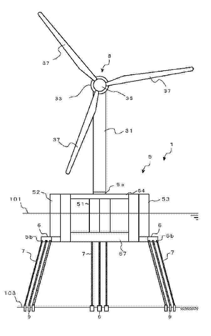
The present invention addresses the problem of providing a taut-moored floating structure that is taut-moored by a plurality of taut mooring cables, the taut-moored floating structure reducing shaking due to wind or waves, preventing an instantaneous increase in load on the taut mooring cables, and reducing fluctuations in the load on the taut mooring cables when shaking occurs. The problem is solved by a taut-moored floating structure 1 that supports an offshore wind power generation system, the taut-moored floating structure comprising a floating structure 5 and three sets of taut mooring cables 7 that connect seabed mooring parts 9 fixed to the seabed and connection parts 5b. Each column 51, 52, 53 of the floating structure 5 is provided with the connection parts 5b on an outside portion of an overhang part 6 overhanging outward. Each set of taut mooring cables 7 is composed of at least three taut mooring cables. When tension is generated in each taut mooring cable 7 by buoyancy generated in the floating structure 5 and the floating structure 5 is held in a tautly-moored state, distances between one set of taut mooring cables 7 which are connected to one column 51 are substantially equal to each other and are between the connection parts 5b and the seabed mooring parts 9, and an angle formed by the one set of taut mooring cables with respect to a vertical line is 15° or less.
Resumen de: WO2026042428A1
Provided is a floating offshore wind turbine system having a structure useful for replacing large components of a floating offshore wind turbine. A floating offshore wind turbine system having a floating offshore wind turbine, a main floating body, and a mooring body, the floating offshore wind turbine system characterized in that: the floating offshore wind turbine has blades for receiving wind, a hub to which the blades are fixed, a nacelle for storing a generator for converting rotational energy of the hub into electric power, a tower for supporting the nacelle, a sub-floating body for supporting the tower, and a sub-floating body connection part that can be fitted to a transport ship connection part; and the main floating body is moored to the sea bottom by the mooring body, and has a sub-floating body insertion space into which the sub-floating body is inserted.
Resumen de: US20260055756A1
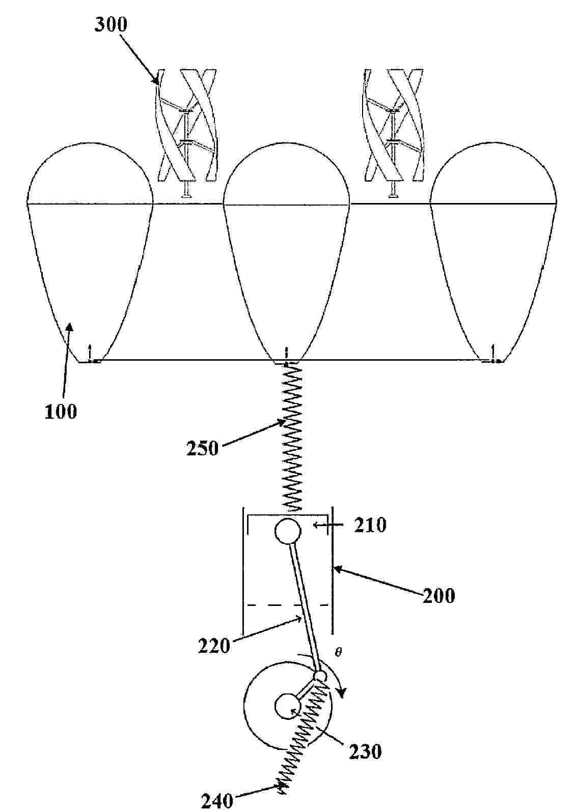
A combined stationary solar CSP, wave motion, and wind power generation and fresh water production system that deploys close structure non-imaging non-tracking solar concentrator array as buoy for wave motion converter system and floating platform for wind mills comprises a divergent Fresnel lens and non-imaging concentrator enabled non-imaging non-tracking solar concentrator based hybrid solar thermal and photovoltaic CSP system, a wave energy converter system, and a vertical axis wind energy system. Wherein, the stationary solar CSP system realizes ultra-high efficiency through solar thermal and photovoltaic cogeneration, substantially-low cost through stationary high concentration ratio concentration, and super-stable power generation through electrothermal energy storage. The system produces fresh water through thermal power generation and uses swappable battery modules to address power transportation and utilization issues.
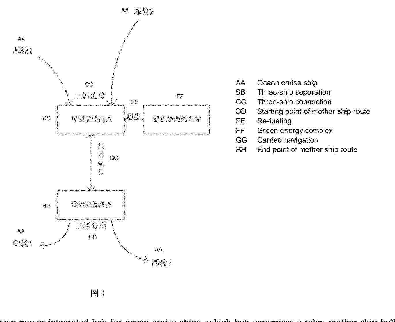
Resumen de: WO2026041034A1
A green power integrated hub for ocean cruise ships, which hub comprises a relay mother ship hull (1) and a green energy complex. The relay mother ship hull (1) cruises on a fixed schedule along a designated route between fixed locations. The green energy complex is arranged at the starting point of the route of the relay mother ship hull (1) and is used for re-fueling the relay mother ship hull (1). Ten connection assemblies are respectively arranged on two sides of the relay mother ship hull (1) and are used for connecting cruise ships (16) located on both sides. Two personnel access galleries (17) are respectively connected to the two sides of the relay mother ship hull (1) and are used for communicating the cruise ships (16) on both sides with the relay mother ship hull (1). Each connection assembly comprises a structural reinforcing member (14), a connecting arm support (13), a connecting arm device (12) and a hull connecting member (11). The structural reinforcing member (14) is arranged on a side wall of the relay mother ship hull (1).
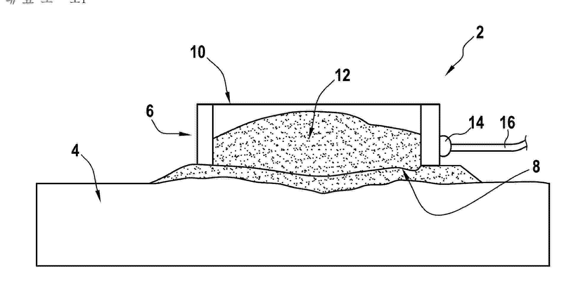
Resumen de: CN120916941A
The invention relates to a system (2) for forming an anchor point for an offshore wind turbine float, comprising at least one enclosure (6) having an open bottom (8) and an open top (10), the enclosure being at least partially filled with a solid particulate material (12) capable of withstanding shear forces with a seabed (4) on which the enclosure is intended to sit, the enclosure further comprises at least one mooring lug (14) for securing a mooring line (16) of the float.
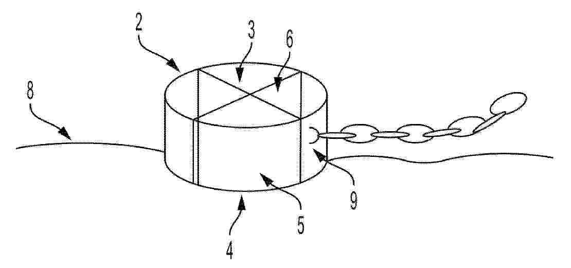
Resumen de: TW202442530A
Device 1 for anchoring in a seabed 8 comprising - a hollow cylinder 2 comprising: - an open upper base 3, - an open lower base 4 configured to be embedded in the seabed, - a peripheral wall 5 with an internal face and an external face, - an internal stiffening structure 6 attached to the internal face of the hollow cylinder and extending axially within the cylinder between the lower and upper bases of the cylinder, and - an anchoring chain fastening means 9 rigidly connected to the hollow cylinder.
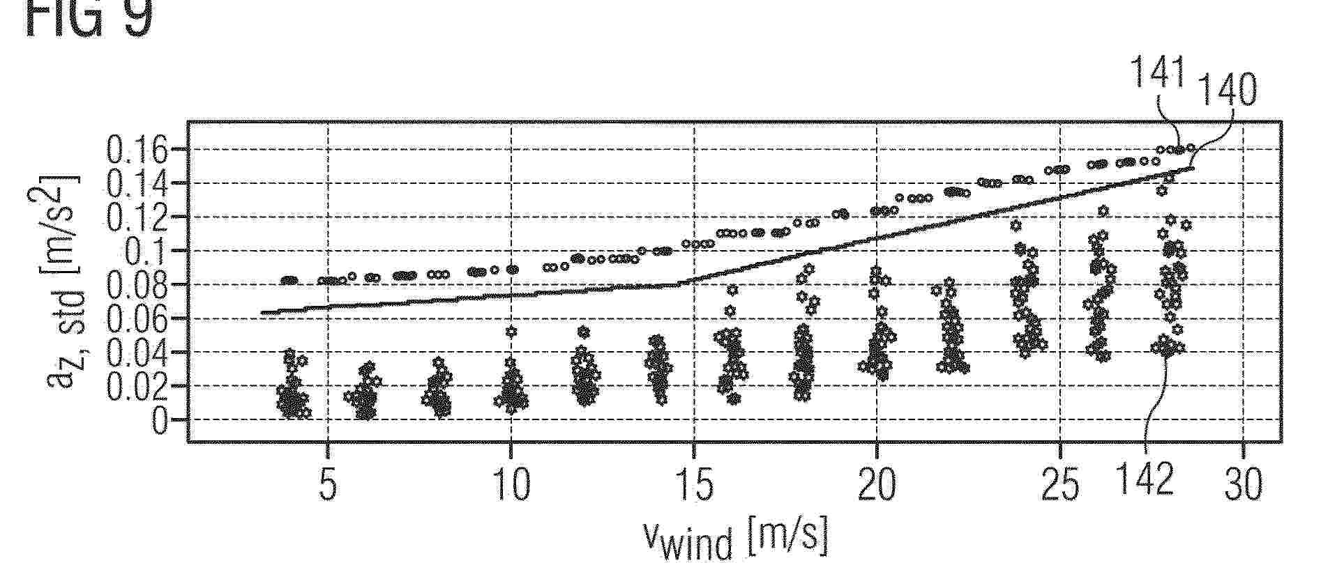
Resumen de: EP4700235A1
A method of operating a floating wind turbine (1), FWT, is provided. The floating wind turbine (1) is exposed to waves during operation, the waves causing a wave induced motion of the floating wind turbine (1). The floating wind turbine (1) is configured to operate a protective function. The method comprises obtaining, during operation of the floating wind turbine (1), monitored wave data (70) indicative of a wave height of the waves the floating wind turbine (1) is exposed to during operation. It further comprises processing the monitored wave data (70) to obtain processed wave data, wherein the processing comprises at least a processing by descriptive statistical analysis, comparing the processed wave data to a threshold (140) that corresponds to a predetermined sea state and activating the protective function upon detecting that the processed wave data reaches or exceeds the threshold (140).
Resumen de: CN223934910U
The utility model relates to the technical field of light-emitting buoys, in particular to an electromagnetic water area light-emitting buoy device which comprises a buoy body, a wind power generation assembly arranged at the upper end of the buoy body, a control room controlled in the middle of the buoy body, a generator room arranged at the upper end of the control room and a light-emitting device arranged in the generator room. The floating buoy has the advantages that the matched small wind power generation assembly is arranged, power can be provided for the lamp when the floating buoy works on the water surface, the light emitting effect of the floating buoy is guaranteed, light reflecting stickers are attached to the surfaces of fan blades of the wind power generator, and when an external light source irradiates the floating buoy, the light reflecting stickers can reflect light, so that the light reflecting effect is good. The integral structure is split and can be detached and replaced, the balance block at the lower end can improve the stability in water, a balance weight can be added to adjust the depth of the buoy in the water, and the buoy is suitable for being used in water areas with different densities.
Resumen de: CN223938180U
The utility model discloses a floating type ocean energy conversion charging platform, which comprises a floating platform, a wind energy collecting mechanism and a plurality of lifting type charging mechanisms, and is characterized in that the wind energy collecting mechanism is provided with an upright post fixed in the floating platform in a penetrating manner, a fan arranged at the upper end of the upright post, and an equipment cabin built in the bottom of the upright post; an energy conversion device is arranged in the equipment cabin, the lifting type charging mechanisms are installed on the periphery of the floating platform at equal intervals through an installation frame, the lifting type charging mechanisms, the draught fan, the solar panel and the wave energy collection mechanism are all electrically connected with the energy conversion device in the equipment cabin, and collected wind energy, solar energy and wave energy are converted into electric energy.
Resumen de: AU2024320056A1
A method for transferring a first end (12) of a power cable (10) from a floating vessel (520) to an offshore structure (100) such that the first end (12) remains above sea level (40), and a system therefore. The system comprises a floating vessel (520); an offshore structure (100) positioned in the vicinity of the vessel (520); and a transfer apparatus (500) comprising a zip line arrangement comprising a zip line (540) extending between a first connection (501) positioned on the offshore structure (100), to a second connection (502) positioned on the floating vessel (520). A cable mounting device (550) is positioned on the zip line (540) and configured to receive a first end (12) of a power cable (10). The cable mounting device (550) is moveable along the zip line (540) for the transfer, above sea level (40), of the first end (12) of the power cable (10) between the floating vessel (520) and the offshore structure (100). The method comprises providing the system; providing the first end (12) of the power cable (10) at the vessel (520); attaching the first end (12) of the power cable (10) to the cable mounting device (550); and moving the first end (12) of the power cable (10) from the vessel (520) to the offshore structure (100).
Resumen de: WO2026038959A1
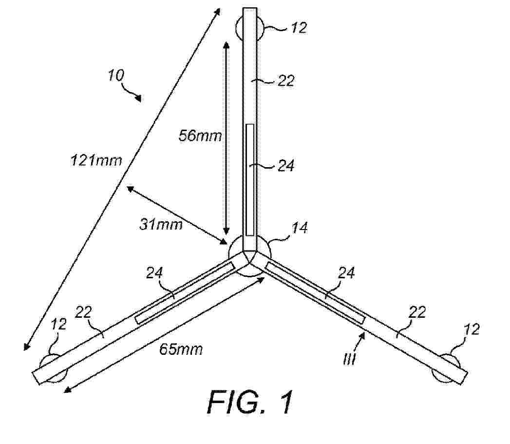
The invention relates to a vertical axis turbine comprising a rotor and a frame for supporting the rotor, said frame comprising: - a top support with a bearing for the rotor, - a base support, and - six rigid legs, wherein the six rigid legs are attached in pairs to three mounting positions on the base support, and wherein the six rigid legs are attached in pairs different from the pairs formed at the base support to three mounting positions on the top support, wherein the three mounting positions on the base support lie on a first virtual circle with a first diameter, wherein the three mounting positions on the top support lie on a second virtual circle with a second diameter, and wherein the first diameter is larger than the second diameter.
Resumen de: US20260048818A1
A floating power-generation group comprises a floating hub such as a spar buoy that is anchored to subsea foundations by anchor lines. Floating power producer units such as wind turbines are connected electrically and mechanically to the hub. The power producer units are each moored by mooring lines. At least one mooring line extends inwardly toward the hub to effect mechanical connection to the hub and at least one other mooring line extends outwardly toward a subsea foundation. The groups are combined as a set whose hubs are connected electrically to each other via subsea energy storage units. Anchor lines of different groups can share subsea foundations. The storage units comprise pumping machinery to expel water from an elongate storage volume and generating machinery to generate electricity from a flow of water entering the storage volume. The pumping machinery can be in deeper water than the generating machinery.
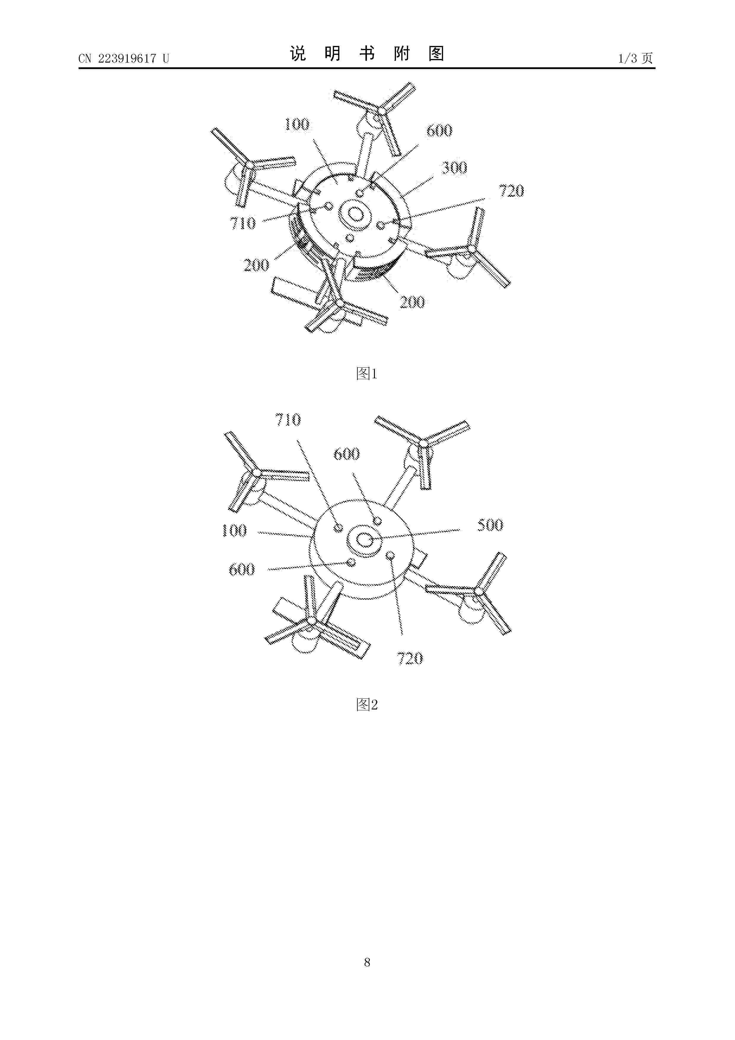
Resumen de: CN223919617U
The utility model belongs to the technical field of unmanned aerial vehicles, and discloses a marine unmanned aerial vehicle device. The offshore unmanned aerial vehicle device comprises an unmanned aerial vehicle body and a plurality of buoyancy assemblies. The multiple buoyancy assemblies are fixed to the outer side wall of the unmanned aerial vehicle body and evenly distributed in the circumferential direction of the outer side wall of the unmanned aerial vehicle body at intervals. Each buoyancy assembly comprises an arc-shaped floating plate and a plurality of floating rings, the arc-shaped surface of each arc-shaped floating plate is parallel to the outer side wall of the unmanned aerial vehicle body, the floating rings are stacked in the vertical direction, and the arc-shaped floating plates and the floating rings can float in water. The marine unmanned aerial vehicle device can be prevented from sinking into water after falling into water, and is good in stability and compact in structure.
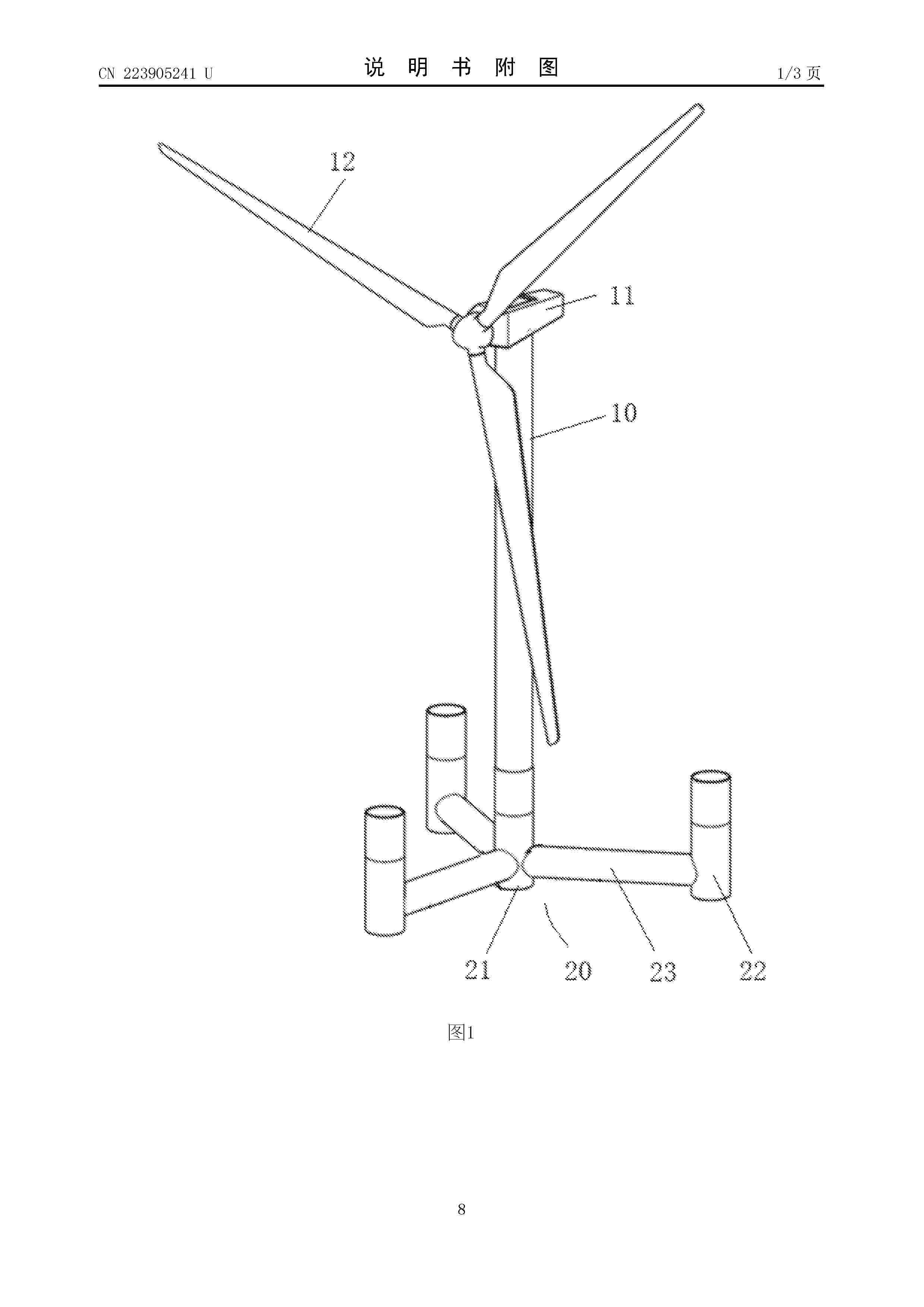
Resumen de: CN223905241U
The low-frequency tuning liquid column damper comprises three horizontal tuning liquid columns which are annularly and evenly distributed, and vertical tuning liquid columns are arranged at the outward ends of the three horizontal tuning liquid columns in the radial direction correspondingly; the horizontal tuning liquid column comprises a horizontal snakelike pipeline, and a first horizontal pipe section and a second horizontal pipe section are arranged at the two ends of the horizontal snakelike pipeline respectively; the vertical tuning liquid column comprises a vertical snakelike pipeline, and a vertical pipe section is arranged at the lower end of the vertical snakelike pipeline; the horizontal tuning liquid column and the vertical tuning liquid column are connected through the adjacent first horizontal pipe section and vertical pipe section; the three adjacent second horizontal pipe sections among the three horizontal tuning liquid columns are communicated with one another; a damping valve is arranged in the second horizontal pipe section, and the horizontal tuning liquid column and the vertical tuning liquid column are filled with damping liquid. The utility model further discloses a four-buoy semi-submersible type floating body platform and an offshore wind turbine, and the four-buoy semi-submersible type floating body platform and the offshore wind turbine can adapt to the low-frequency vibration characteristic of the semi-submersible type platform.
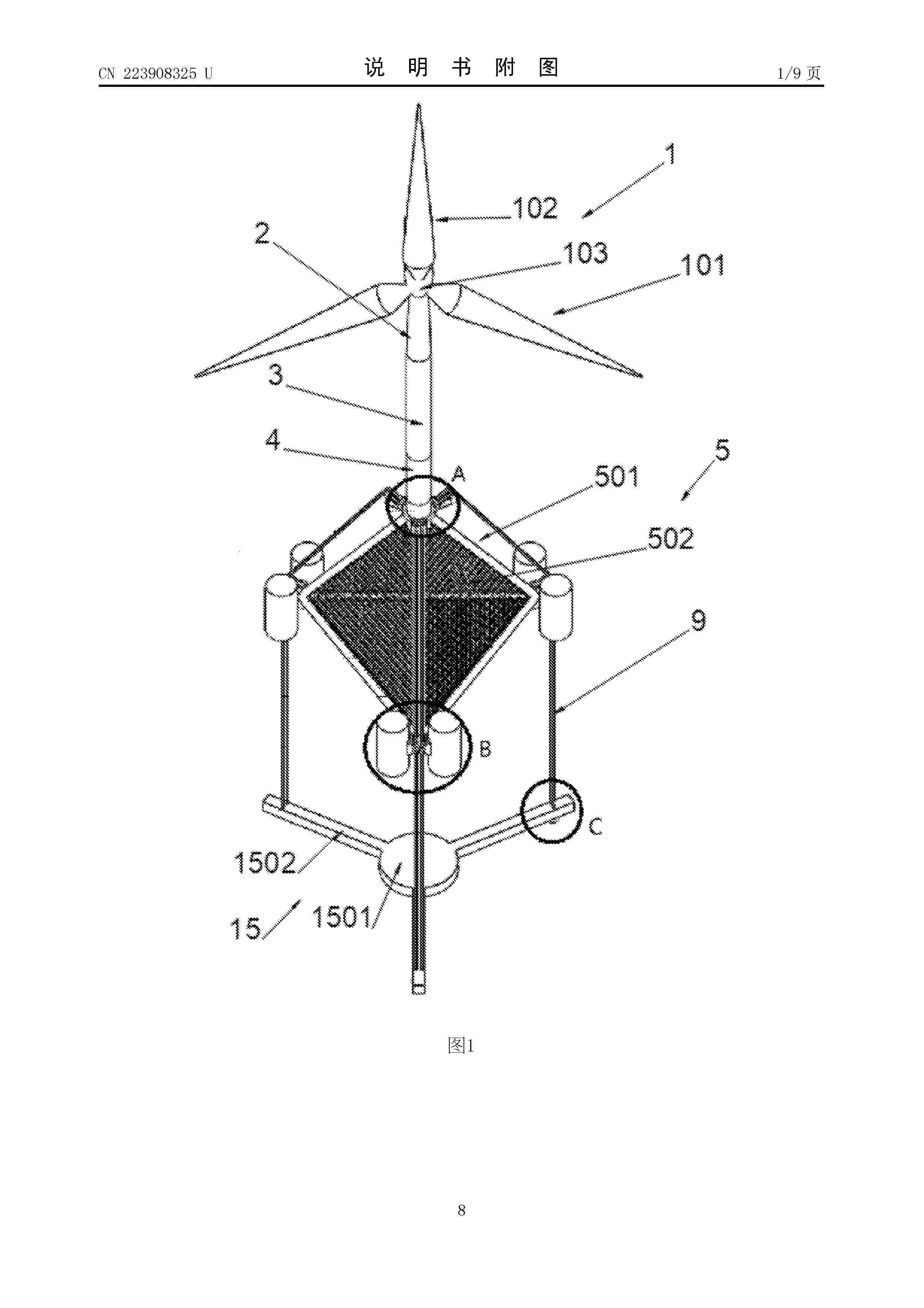
Resumen de: CN223908325U
The utility model belongs to the technical field of offshore wind power generation and fishery breeding, and particularly discloses an offshore wind and fish fusion tension leg floating type wind power platform which comprises an upper fan, a platform foundation and an anchoring foundation, and the upper fan is formed by assembling an upper tower drum, a middle tower drum, a bottom tower drum, a cabin, a hub and fan blades; the platform foundation comprises a main body, a bearing platform is arranged at the top of the main body, a bottom tower drum is fixedly connected to the bearing platform, the platform foundation is connected with a plurality of angular point buoys, accessory components are arranged on the bearing platform in the circumferential direction, a plurality of anchor gears are arranged on the accessory components in the circumferential direction, and anchor chains are wound on the anchor gears; the anchoring foundation comprises a ballast component, and the ballast component is movably connected to the bottom of the platform foundation through an anchor chain. The wind and fish integrated development mode is utilized, space can be provided for fishery breeding, wind power generation can be carried out, comprehensive cost is reduced, and meanwhile maximum utilization of sea space is achieved.
Resumen de: US20260042517A1
The disclosure relates to a floating wind turbine platform, comprising: a substantially triangular hull configurable to support a wind turbine tower; the hull comprising a first, second and third column, the first, second and third columns being connected by a first, second and third pontoon member, as well as by a first, second and third connector.
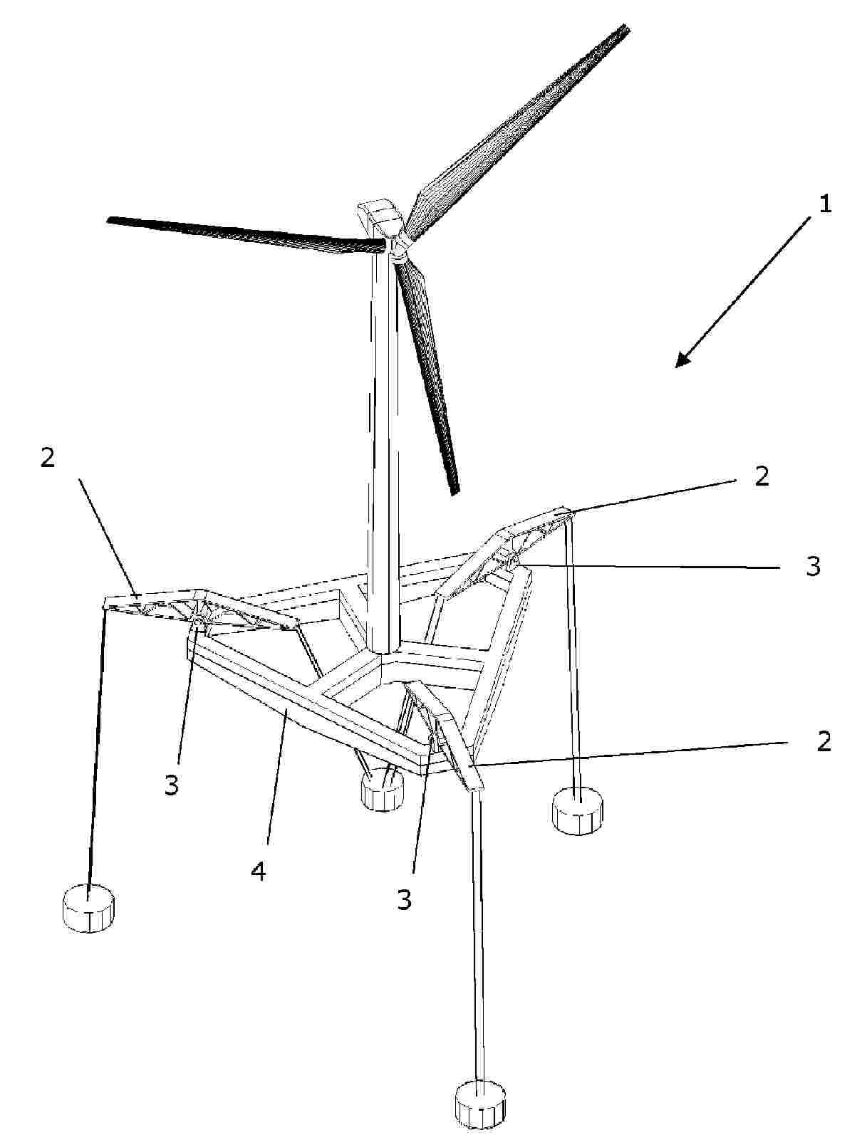
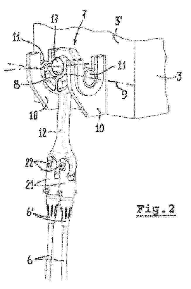
Resumen de: US20260042509A1
Anchoring system having a floating platform from which first anchoring lines emerge, an anchoring block with at least three non-aligned anchoring points, a central float swinging arms being joined by a joint to the block, the joint located in an intermediate area so that each arm has an internal section and an external section, the internal section located between the intermediate area and an inner free end, and the outer section located between the intermediate area and an outer free end, the inner end closer to the central float than the outer end, so that first anchoring lines leaving the floating platform are joined to the outer free ends. The system has second anchoring lines between the central float and the inner end portions containing the inner free ends of the inner sections of the arms. Also a method of install and uninstalling such a system.
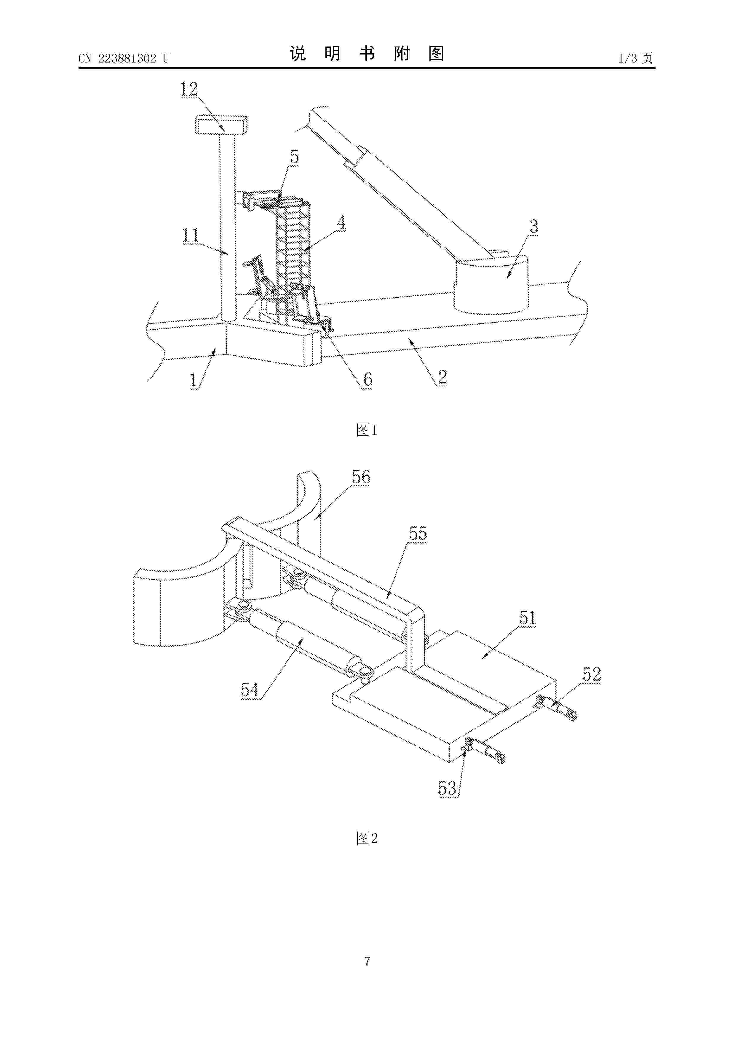
Resumen de: CN223881302U
The utility model discloses a floating type fan installation, operation and maintenance device which comprises a floating type foundation, a wind turbine generator set, a wind turbine generator set, a wind turbine generator set, a wind turbine generator set, a wind turbine generator set, a wind turbine generator set and a wind turbine generator set. A truss is installed on the side, close to the cabin, of the platform, and a tower clamping mechanism is arranged on the upper portion of the truss; and the foundation clamping mechanisms are symmetrically arranged on the two sides of the truss, and the two foundation clamping mechanisms and the tower clamping mechanism are distributed in a triangular shape. The floating fan is clamped through the tower clamping mechanism and the two foundation clamping mechanisms which are arranged on the platform, so that the floating fan and the platform form a relatively stable whole, the problem that the mounting platform and the floating foundation shake relatively is solved, and relative stability in the hoisting operation process is guaranteed.
Resumen de: US20260035055A1
A disconnectable mooring system for offshore semi-submersible floating structures. A disconnectable buoy has a number of mooring lines which include a buoy chain between the mooring chain and the buoy. The mooring chain and the buoy chain are connected via a three way mooring connector, with the third connection configured to pull the mooring connector to a mooring point on the structure. In a first configuration the buoy is disconnected and supports the mooring chains for recovery at shallow depths to be pulled in. In a second configuration, the mooring lines are pulled in via the mooring connectors thereby providing a spread mooring to the structure with the buoy chain left as a catenary between the buoy and mooring point.
Resumen de: US20260036115A1
The present invention concerns a method for determining the production availability of an offshore wind farm comprising at least one floating wind turbine, the method comprising: obtaining wind farm data, obtaining strategy data relative to operation and maintenance resources to carry out an action on the floating wind turbine(s), obtaining meteorological data relative to an offshore environment for the offshore wind farm over a given period of time, determining motion parameters as a function of the wind farm data and of the meteorological data, and determining the production availability of the offshore wind farm in the offshore environment over the given period of time on the basis of the wind farm data, of the strategy data, of the meteorological data, and of the determined motion parameters.
Resumen de: US20260034905A1
Provided is a moving body used in a power transmission system that charges a storage battery mounted on the moving body with power generated by a power generation facility and feeds the power to a power receiving facility from the storage battery transported by the moving body. This moving body is provided with a battery control device that causes the storage battery to be charged with the supply of power based on a voltage value that does not reach a maximum voltage value of direct-current power between the power generation facility and the power receiving facility.
Resumen de: EP4686827A1
A method of controlling a motion of an offshore wind turbine (OWT) is provided. The OWT (100) comprises a tower (101), a wind turbine rotor (102), and a generator (120), wherein the generator (120) is mechanically coupled to the wind turbine rotor (102) and is configured to convert mechanical power to electrical power. The method comprises operating the OWT in an active motion control mode in which a motion of the OWT is controlled. Operation in the active motion control mode comprises operating the wind turbine rotor (102) to cause an application of a torque and/or force to an upper part of the tower (101) of the OWT to control the motion of the OWT. The wind turbine rotor (102) is operated by actively controlling a torque applied by the generator (120) to the wind turbine rotor (102).
Resumen de: CN223865079U
The utility model discloses a floating type draught fan platform which comprises a buoy temporarily supported on a supporting column, the buoy is connected with the draught fan platform through a vertical steel cable, during construction, after a draught fan is provided with part of components, the draught of the floating type draught fan platform is increased, the buoy is emptied to provide vertical buoyancy, part of the weight of the draught fan is offset, and after the draught fan is hoisted, the buoy is connected with the draught fan platform through the vertical steel cable. The method comprises the following steps: dragging a floating fan platform to a deepwater area, injecting water into the platform to sink in the deepwater area, injecting water into the buoy to sink, and after the buoy is supported on a supporting structure of the platform, releasing a vertical connecting steel cable of the buoy and the platform, draining ballast water of the buoy, floating the buoy, separating from the platform, assisting in displacement of the buoy, and finishing installation of the fan. Construction is completed under the condition that the water depth of a wharf is insufficient by combining the separated floating cylinder with the fan platform.
Resumen de: CN223872020U
A floating fan dynamic submarine cable comprises a floating foundation and a submarine cable body fixed to the bottom of the floating foundation, and the submarine cable body comprises a vertical buffer section and a horizontal buffer section which are arranged in sequence; a bending clamp structure is arranged outside the vertical buffer section and is used for bending the vertical buffer section; and a bending floating structure is arranged outside the horizontal buffer section and is used for bending the horizontal buffer section. According to the invention, the defect of mechanical damage caused by repeated stretching of the dynamic submarine cable can be overcome.
Resumen de: US20260028107A1
An energy collecting method includes: a step in which a floating body, which constitutes a power generation system, stores energy by the floating body generating power while automatically sailing; and a step in which an energy transport ship collects energy from the floating body near an edge of a sea area in which the floating body automatically sails.
Resumen de: US20260028098A1
A mobile energy harvesting device and method for using the same are described. In one embodiment, the device comprises a hull with a steering system, wherein the steering system steers the device. The device also includes a sail coupled to the hull and configured to propel the mobile energy harvesting device. An energy storage device is coupled to the hull and is configured to store energy. The device also further includes one or more energy generation devices configured to produce energy to be stored in the energy storage device. A control system is positioned in the hull and includes a control center communicatively coupled to a sensor, wherein the sensor detects input and communicates the input to the control center and the control center communicates with the steering system to steer the mobile energy harvesting device.
Resumen de: CN223821970U
A semi-submersible offshore floating type fan installation platform comprises a fan installation platform body and a three-stand-column type fan foundation, the fan installation platform body moves towards the three-stand-column type fan foundation, one stand column of the three-stand-column type fan foundation is provided with a conical groove and a fan floating body winch, and the installation platform body is provided with a butt joint groove and a platform winch. A stand column with a conical groove is inserted into the butt joint groove, a mooring rope is arranged between the fan floating body winch and the platform winch, hydraulic anti-collision devices at the two ends are started to clamp the stand column, and after the stand column is fixed, a hydraulic bolt is started, and a hydraulic rod of a locking hydraulic cylinder is inserted into the conical groove to be fixed. The floating body of the floating fan and the platform can be combined into a floating structure in an operation sea area of the floating fan, and the floating body and the platform are relatively static, so that good conditions are provided for fan installation, and the installation operation of the floating fan on the sea is completed. And the offshore installation operation of the floating fan is realized.
Resumen de: CN223825175U
The utility model discloses an anti-corrosion protective device for an offshore wind power tower drum, which relates to the technical field of protective devices and comprises two symmetrically arranged semicircular mounting sleeves and two symmetrically arranged semicircular stroke sleeves, the semicircular mounting sleeves are sleeved on the outer drum walls of the semicircular stroke sleeves, and the semicircular stroke sleeves are sleeved on the outer drum walls of the semicircular stroke sleeves. A stroke block is fixedly connected to the outer cylinder wall of the semicircular stroke sleeve, a matched stroke groove corresponding to the stroke block is formed in the cylinder wall of the semicircular mounting sleeve, the offshore wind power tower cylinder can be effectively prevented from being collided through the arrangement of the mounting sleeve and the stroke sleeve, and a floating plate on the semicircular stroke sleeve can generate buoyancy along with the impact of sea waves. The buoyancy of the floating plate can drive the cleaning semi-ring in the semicircular stroke sleeve to clean the outer wall of the offshore wind power tower, dirt and marine organisms attached to the outer wall of the offshore wind power tower can be effectively scraped off, and the offshore wind power tower can be effectively prevented from being corroded.
Resumen de: US20260022686A1
The invention relates to a mooring system comprising a floating platform (1) with a plurality of mooring lines (7) configured to fix or anchor the floating platform (1) to the seabed by means of a bottom section (71) of each mooring line (7), wherein each mooring line (7) also comprises a central section (72) joined to a counterweight (8), wherein tilting arms (2) are joined by means of an articulated joint (3) to a main structure (4) of the floating platform (1), wherein each tilting arm (2) comprises an inner section (21) and an outer section (22), wherein the bottom section (71) and the central section (72) of each mooring line (7) are respectively joined to a terminal end of the outer section (22) and to a terminal end of the inner section (21) of each tilting arm (2).
Resumen de: WO2026017251A1
A tension leg platform assembly is provided, comprising a buoyant body and a number of mooring assemblies attached thereto, which extend between the buoyant body and a fixed foundation on the seabed. Each mooring assembly comprises at least one elongate member having an upper end and an opposite lower end. At least one of said upper end and lower end by means of a connector assembly is connected to the buoyant body or the fixed foundation, respectively. Said connector assembly is provided with a first yoke which is connected to the buoyant body or fixed foundation for a rotation around a first axis which extends substantially horizontally at a first level, and a second yoke attached to the elongate member which is mounted in the first yoke for a rotation around a second axis which extends substantially perpendicularly to the first axis at a second level. The second level is further away from the upper end or lower end, respectively, of the elongate member than the first level.
Resumen de: WO2026019171A1
Disclosed is a floater for a floating offshore wind power generator, comprising: columns; and connection structures connecting the columns. According to a first embodiment, each of the columns may be provided with a sliding groove having an open upper end and extending in a vertical direction. Each of the connection structures may be slidably coupled to the sliding groove through the open upper end. According to a second embodiment, the columns may comprise: a central column having a wind power generator coupled to the top surface thereof; and a plurality of outer columns spaced apart from each other at regular angular intervals around the central column and providing buoyancy. The connection structures may comprise: an internal connection structure installed between the central column and the outer columns to establish an internal connection arrangement; and an external connection structure installed between the plurality of outer columns to establish an external connection arrangement.
Resumen de: US20260022687A1
A semi-submersible platform for supporting wind turbines comprising a mixed structure with two portions: a first concrete caisson-type structure, which serves as hydrodynamic stability and flotation of the platform, consisting of: a hollow, closed base plate, and cylindrical and/or frustoconical-shaped bodies, the bases of which are embedded in the base plate, in areas close to the vertices thereof, which are closed at the top by covers; and, a second structure formed by a transition piece that connects the base plate to the lower end of the tower of the wind turbine at connection points, located on each side of the base plate, distributing the service loads of the wind turbine towards the concrete caisson-type structure.
Resumen de: AU2024234263A1
A tendon (224) for a tension leg platform (202), TLP, is provided. The TLP comprises a foundation (206), connectable to a bottom (208) of a body of water, and a buoyant hull (216). The tendon has a length, a proximal end (223), and a distal end (225). The tendon comprises a proximal end fitting at the proximal end and a distal end fitting at the distal end. The tendon is connectable with the proximal end fitting to the hull and with the distal end to the foundation to provide a pulling force on the hull. The length of the tendon is at least 300 meters. The tendon comprises basalt fibres for transferring the pulling force from the proximal end fitting to the distal end fitting.
Resumen de: CN223806237U
The utility model relates to the technical field of floating power generation, in particular to a portable mooring type floating power generation device which comprises a floating air bag, an air inlet duct is formed in the floating air bag, a wind driven generator is detachably installed on the inner wall of the air inlet duct through a connecting structure, and fan blades are fixed to an output shaft of the wind driven generator. The connecting structure is arranged between a shell of the wind driven generator and the inner wall of the tail end of the floating air bag and comprises two sets of fixing rods fixed to the shell of the wind driven generator, the outer ends of the fixing rods in each set are jointly connected with a fixing ring, and clamping heads corresponding to the fixing rods are fixed to the inner wall of the floating air bag. The two groups of clamping heads are oppositely arranged; the connecting piece is arranged between a pair of opposite clamping heads. The joints of the fixing rings and the fixing rods are clamped into the clamping connectors, then the joints of the two fixing rings and the two fixing rods abut against the interiors of the corresponding clamping connectors through the fixed sleeves and the movable sleeves, and the installation mode is simple and rapid.
Resumen de: US20260015811A1
In a general aspect, suction anchors are presented for securing structures to an underwater floor. The suction anchors include a tubular body formed at least in part of cementitious materials and having a closed end and an open end. The tubular body includes an edge defining an opening for the open end. The edge is configured to penetrate the underwater floor. The suction anchors also include a port configured to fluidly-couple a cavity within the tubular body to an exterior of the tubular body. The suction anchors additionally include a pad eye extending from an outer surface of the tubular body and configured to couple to a mooring line. In another aspect, methods of manufacturing the suction anchors are also presented.
Resumen de: AU2025283585A1
WIND-POWERED COMPUTING BUOY Disclosed is a novel type of computing apparatus which is integrated within a buoy that obtains the energy required to power its computing operations from winds that travel across the surface of the body of water on which the buoy floats. Additionally, these self-powered computing buoys utilize their close proximity to a body of water in order to significantly lower the cost and complexity of cooling their computing circuits. Computing tasks of an arbitrary nature are supported, as is the incorporation and/or utilization of computing circuits specialized for the execution of specific types of computing tasks. And, each buoy’s receipt of a computational task, and its return of a computational result, may be accomplished through the transmission of data across satellite links, fiber optic cables, LAN cables, radio, modulated light, microwaves, and/or any other channel, link, connection, and/or network. ec - e c
Resumen de: AU2025283459A1
Disclosed is a floating, self-regulating hydroelectric computer network comprising a water turbine, a hull adapted to float at a surface of a body of water and confine a water reservoir and impel a flow of pressurized water to the water turbine, an electrical generator operatively coupled to the water turbine, a power-conditioning module operatively connected to the electrical generator, an electrical load bus, a plurality of computers operatively connected to the power-conditioning module via the electrical load bus, a phased-array antenna operatively networked with the plurality of computers to transmit data from the plurality of computers to satellites, and a load manager configured to alter a rate of program execution of the plurality of computers. ec e c
Resumen de: US20260015065A1
A floating structure (1) having three buoyant bodies (3,5,7) for supporting a horizontal axis wind turbine (6) and wind turbine tower (27). The floating structure (1) is provided with a geostationary mooring system that permits it to weathervane in order to head the wind turbine (6) into the wind, and has a wind turbine tower mount (29) for supporting the wind turbine tower (27). A central buoyant body (3) is located partially above water during assembly and tow out from port and is ballasted so that it is underwater when moored offshore, such that the floating structure (1) becomes a semi-submersible. The three buoyant bodies (3,5,7) are ship-shaped in form which reduces loads in the mooring system, and are made from stiffened flat plates, which are easier for many yards and fabrication shops to make, compared to cylindrical hulls.
Resumen de: WO2026013445A1
A floater for a floating offshore wind turbine comprises a turbine support and buoyancy structures connected to the turbine support by respective arms, each joined to a brace that is also joined to the turbine support. The floater is constructed by joining an inboard end of each arm to the turbine support at a lower fixing point, joining an inboard end of each brace to the turbine support at an upper fixing point, and joining an outboard end of each arm to a respective one of the buoyancy structures at an outer fixing point.
Resumen de: CN120731167A
The invention relates to a method for the large-scale production of floats (2) for offshore wind turbines, each float being formed by the assembly of two to six steel unit giant blocks (B-1, B-2), the method comprising, in order: manufacturing the giant blocks on a dedicated building surface; transporting the giant blocks from the building surface by marine shipping and storing the giant blocks in a storage area (Z-1, Z-2) of a production surface (10) different from the building surface, the same giant blocks being stored on the same storage area; and a final pipelined manufacturing of the floats, comprising, for each float, the following steps in sequence: a step of preparing the giant blocks, a step of assembling and preliminarily welding the giant blocks together in an assembly and preliminary welding zone (Z-3), and a step of assembling and preliminarily welding the giant blocks together in the assembly and preliminary welding zone (Z-3). The assembly and preliminary welding area (Z-3) is different from and adjacent to the storage area, followed by a step of final welding of the giant blocks together in a final welding area (Z-4), and followed by a step of completing the float in a completion area (Z-5), wherein the floating giant blocks and floats move between different regions according to translational motion during manufacturing.
Resumen de: WO2024184625A1
Apparatus and a method of providing a wind turbine (WT) are disclosed. The method comprises the steps of: at a lift position location, erecting a wind turbine portion that comprises at least one elongate tower and a nacelle member on an upper end region of the elongate tower and at least one blade member, by providing a lower tower section at the lift position location, lifting the lower tower section vertically via at least one lift support thereby providing a lifted tower section, urging at least one incoming further tower section to the lift position location, to a position under a preceding tower section, and securing a top region of the incoming further tower section to a lower region of a lifted preceding tower section; whereby lifting tower sections comprises providing tower sections, one-by-one, to the lift position location that is at a desired position proximate to at least one lift support, gripping an incoming tower section via at least one lift beam mounted on respective climber elements movable with respect to each lift support, and via the climber elements raising the gripped tower section upwards to a raised position.
Resumen de: WO2024186911A1
Offshore floating platform systems and processes for mooring same, In some embodiments, the offshore floating platform system can include a hull structure configured to float on a surface of a body of water, one or more anchors configured to be secured to a seabed, and one or more mooring lines configured to be connected to the hull structure at a first end thereof and to the anchor at a second end thereof. When the one or more anchors are secured to the seabed and the one or more mooring lines are connected to the hull structure and a corresponding anchor, the mooring lines can be substantially vertical and a peak response period of the offshore floating platform system in a pitch or a roll direction can be greater than a peak spectral period of a wave spectrum on the surface of the body of water.
Resumen de: WO2024184604A1
The invention relates to a counterweight (2) for a semi-submersible float of an offshore wind turbine, which can be configured to be in a sinking state or a floating state, comprising a counterweight main structure (4) made of a material making it sink when immersed in water, and a plurality of airbags (6, 6') detachably attached to the main structure so as to make the counterweight float when the airbags are inflated. The invention also relates to a method for installing such a counterweight.
Resumen de: EP4678528A1
A floating platform (1) comprising a pedestal frame (100) configured to serve as a support for a structure, wherein the pedestal frame (100) is attached to a bottom plate (200) by means of a plurality of pillars (300) such that, in operating condition, the pedestal frame (100) is supported by the bottom plate (200) by means of the pillars (300), wherein the floating platform (1) comprises a plurality of immersion floats (400) projecting from the bottom plate (200) to an intermediate distance between the bottom plate (200) and the maximum height above the bottom plate (200) of the pillars (300). It also includes a geometry that allows the platform to be manufactured exclusively with flat panels.
Resumen de: CN223778529U
The utility model discloses a modularized floating type offshore wind power platform which comprises a prefabricated center body and a plurality of prefabricated buoyancy cabins, the prefabricated center body is of a steel structure, one ends of the prefabricated buoyancy cabins are connected with the prefabricated center body, the other ends of the prefabricated buoyancy cabins are arranged in a radial mode, and the prefabricated buoyancy cabins are of reinforced concrete structures. And a plurality of split prefabricated modules are connected in sequence. The floating type offshore wind power platform can effectively solve the problems that the concrete wall of the floating type offshore wind power platform is prone to cracking, seawater permeates to corrode the steel bars, fracture and damage of the steel bars are accelerated, and the platform loses efficacy.
Resumen de: WO2026009031A1
A relocatable quay includes a deck that is relocatable in a body of water adjacent a stationary quay. The deck is positioned at the stationary quay to receive a floating unit. The relocatable quay also includes an elevator system positionable to raise and lower the deck to receive the floating unit from the stationary quay and to deploy the floating unit into the body of water.
Resumen de: US20260011995A1
An apparatus that a wind turbine configured for floating on a surface of water, wherein the wind turbine is operable to generate electrical energy. The wind turbine can include a floating base configured to support the wind turbine on the surface of water, and a cable configured to transmit the electrical energy. The wind turbine can also include a first sheave configured to support a part of the cable, and a second sheave configured to support a part of the cable. The cable is reeved between the first sheave and second sheave, and the first sheave is operable to impart a predetermined force to the cable to thereby maintain the cable at a predetermined tension.
Resumen de: WO2026008940A1
The present invention relates to a floating storage structure (2) for storing afloat a constituent member one or more floating wind turbines (4), comprising a flotation means comprising at least one flotation member (20) intended to be submerged and at least one flotation element (22) secured to the flotation member (20), the floating storage platform (2) comprising at least one volume (12) for receiving a constituent member of the floating wind turbine (4).
Nº publicación: WO2026008741A1 08/01/2026
Solicitante:
AKER SOLUTIONS AS [NO]
AKER SOLUTIONS AS
Resumen de: WO2026008741A1
A floatable foundation (100) for a wind turbine generator and/or electrical equipment (61), the foundation (100) comprising: a central column structure (10,11,12); at least three outer column members (20,21,22) disposed about the central column structure (10,11,12); at least three horizontally extending lower connection members, such as pontoon members (30,31,32), each horizontally extending lower connection member fixed to and extending between the central column structure (10,11,12) and a respective one of the at least three outer column members (20,21,22); and three horizontally extending upper connection members, such as beam members (40,41,42), each horizontally extending upper connection member fixed to and extending between the central column structure (10,11,12) and a respective one of the at least three outer column members (20,21,22), wherein each column member (20,21,22) comprises a ballast tank (81) configured for holding water ballast and the ballast tank (81) vertically spans a design waterline (91) of the respective column member (20,21,22).
 BOPI
BOPI
 Sede Electrónica