Si deseas distinguir tus productos, servicios o ambos de los de otra empresa, es posible que necesites una marca o nombre comercial. Descubre qué son, en qué consiste su procedimiento de registro y qué implica.

Información sobre los plazos de presentación de solicitudes de transformación de marcas de la Unión Europea en marca nacional española. Más información


Si tienes un nuevo dispositivo, producto o procedimiento que resuelva un problema técnico o tenga una ventaja práctica, existen distintas formas de protegerlo en España y en otros países. Descubre cómo hacerlo.

¿Tu innovación reside en la estética, la ornamentación o la apariencia de tu producto? Protégela mediante un diseño industrial. Descubre qué derechos confiere el registro y cómo realizar la tramitación.

Las patentes publicadas en todo el mundo son una valiosa fuente de información científica, técnica y comercial.
reembolso del 75% del coste de Búsquedas e Informes Tecnológicos de Patentes. Más información*

Si eres emprendedor/a o una empresa y quieres potenciar y mejorar la rentabilidad de tu negocio protegiendo de forma adecuada los activos intangibles de tu organización, en este espacio encontrarás lo necesario.


 226
resultados
226
resultados
 Última actualización
01/09/2024 [07:09:00]
Última actualización
01/09/2024 [07:09:00]


 Resultados 150 a 175 de 226

Resumen de: US2024282869A1
A device for improving ohmic contact between a front contact and a doped layer of a wafer solar cell having a front, a back, the front contact, the doped layer and a back contact. The front and back contacts are strip-shaped or grid-shaped. The device having: two contacting apparatuses for electrically contacting the front and back contacts; a voltage source having a pole for electrical connection to one contacting apparatus and a pole for connection to the other contacting apparatus; and two point light sources to illuminate the front and the back. The contacting apparatuses each have: an optically-transparent material coated with an optically-transparent, electrically-conductive layer; an optically-transparent material having microscopically-thin, electrically-conductive wires integrated into a surface of the optically-transparent material; an optically-transparent, electrically-conductive material having microscopically-thin, electrically-conductive wires integrated into a surface of the optically-transparent, electrically-conductive material; or, a braid or a network of microscopically-thin, electrically-conductive wires.

Resumen de: US2024282873A1
Protection of space solar cells in an arrangement in the form of a string extending in an X direction, and two directly adjacent space solar cells in the X direction in each case are electrically connected to each other in series with the aid of a metallic connector. The string has a first end and a second end opposite the first end, and a protection arrangement formed along a Y direction is formed on one of the two ends. The protection arrangement has a first string protection diode formed in the Y direction and a metal strip and a second string protection diode. The protection arrangement is electrically connected to one of the two ends of the string and each string protection diode is uncased and has exactly one metal contact on the upper side and exactly one metal contact on the underside.
Resumen de: WO2024169862A1
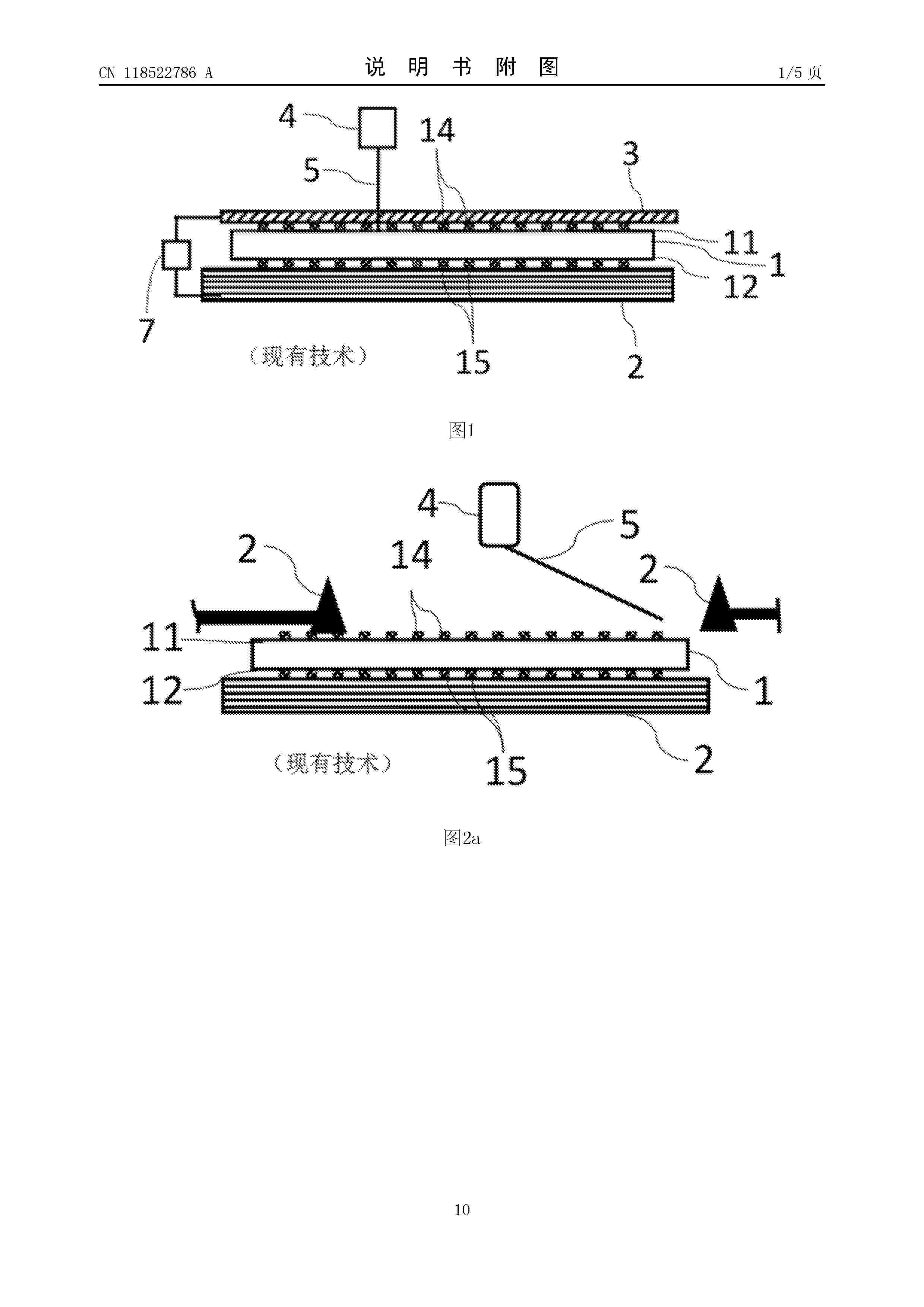
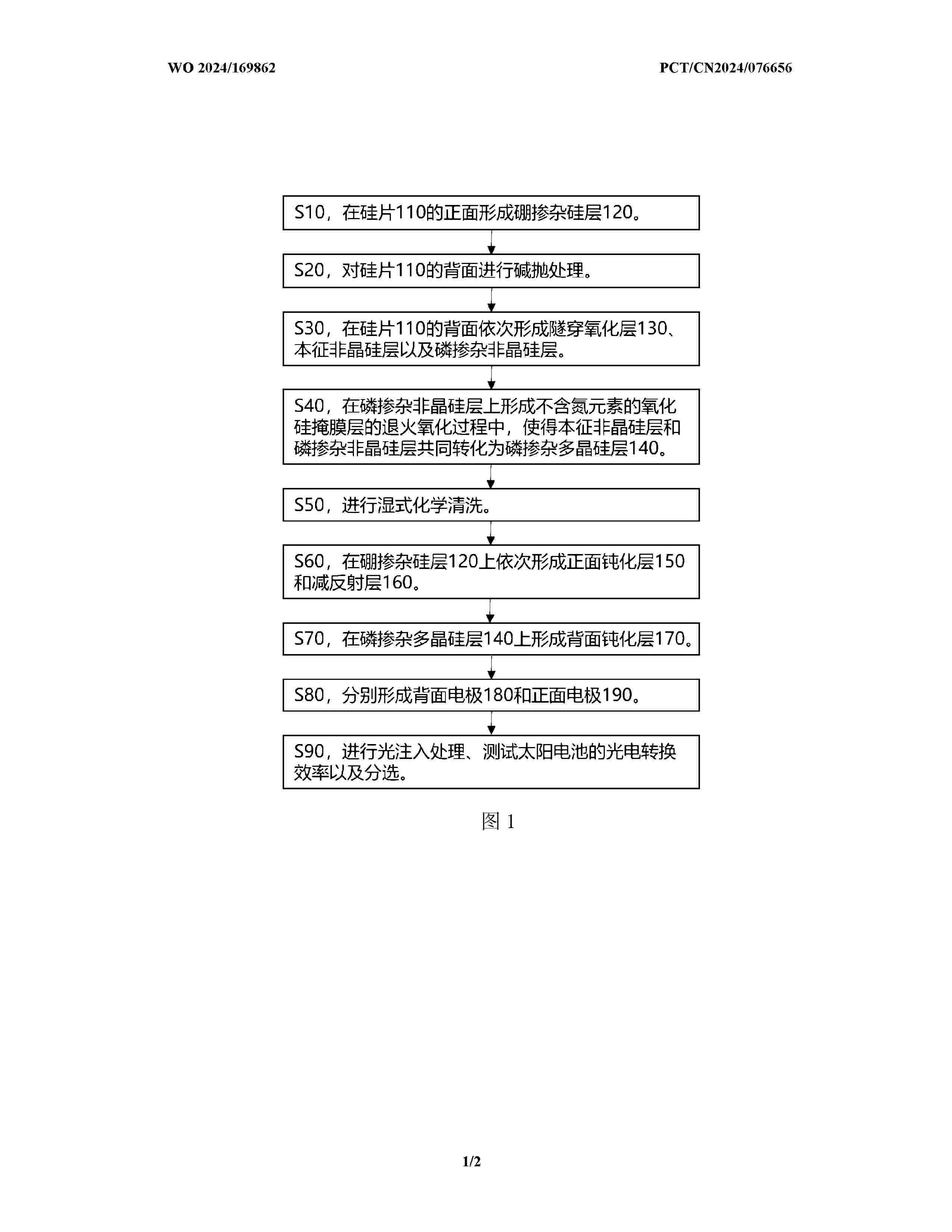
The present application relates to a solar cell and a preparation method therefor. The preparation method for a solar cell comprises: performing annealing oxidization in an atmosphere containing an oxidizing gas at 850-950°C to form a mask layer located on a phosphorus-doped amorphous silicon layer, and converting an intrinsic amorphous silicon layer and the phosphorus-doped amorphous silicon layer into a phosphorus-doped polycrystalline silicon layer together, wherein the mask layer is a silicon oxide layer containing no nitrogen element, and the oxidizing gas comprises at least one of oxygen and ozone.
Resumen de: WO2024169268A1
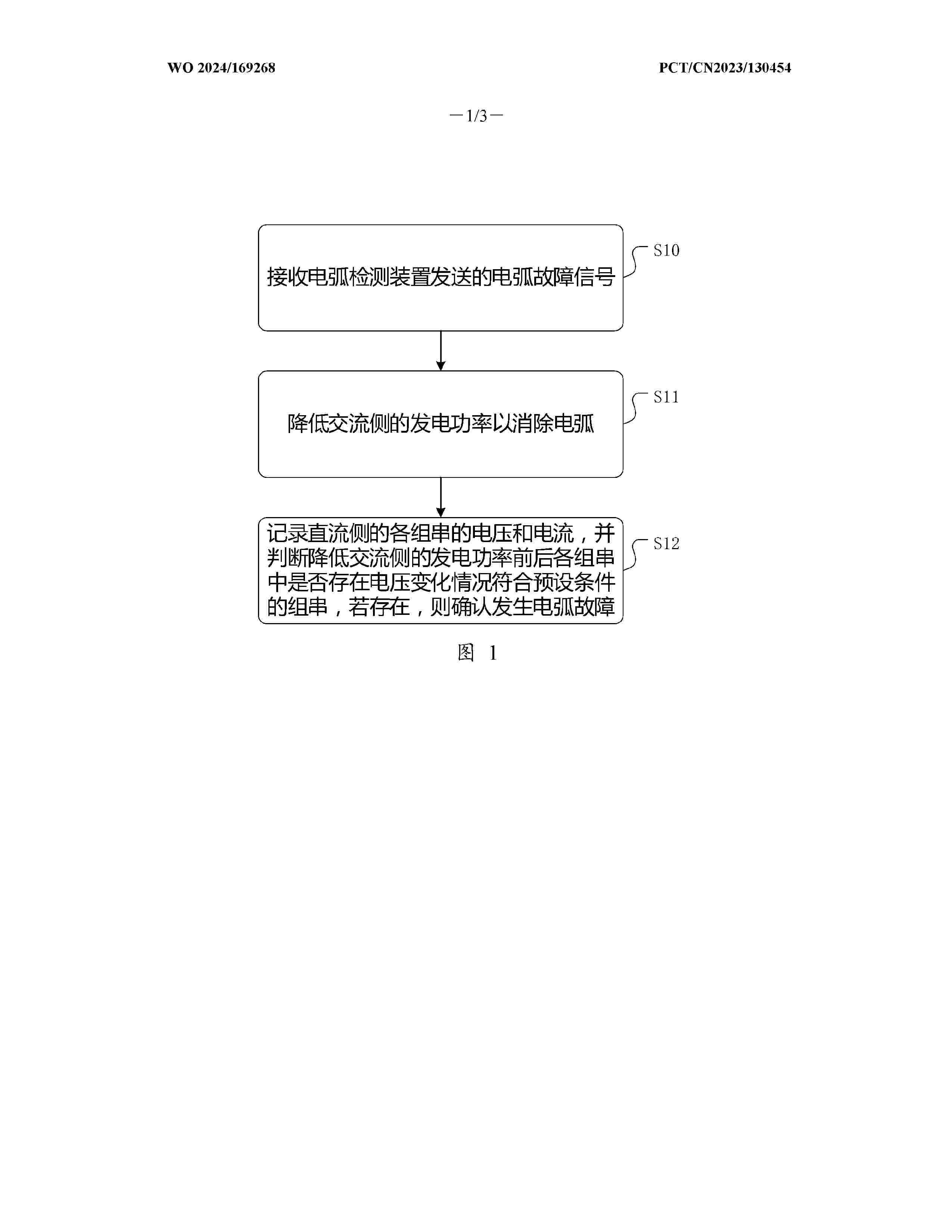
An arc fault confirmation method, an apparatus, and a medium, related to the technical field of power electronics. Compared to the prior art, where an inverter issues an alarm immediately after an arc detection apparatus detects an arc fault signal, leading to the possibility of false alarms, the present technical solution, after an arc detection apparatus detects an arc fault signal, first reduces the power generation on the alternating current side to eliminate any possible arcs and avoid damage to a photovoltaic system caused by real existing arcs. Then, it is determined whether there are any strings with voltage changes that meet preset conditions before and after the power generation is reduced on the AC side; if such strings exist, shut down and issue an alarm. By adopting the present technical solution, after receiving an arc fault signal, an arc extinguishing process is first carried out. Then, based on the voltage changes of each string before and after the arc extinguishing process, it is confirmed whether an arc actually exists. This secondary confirmation method can effectively reduce the occurrence of false arc alarms.
Resumen de: WO2024169166A1
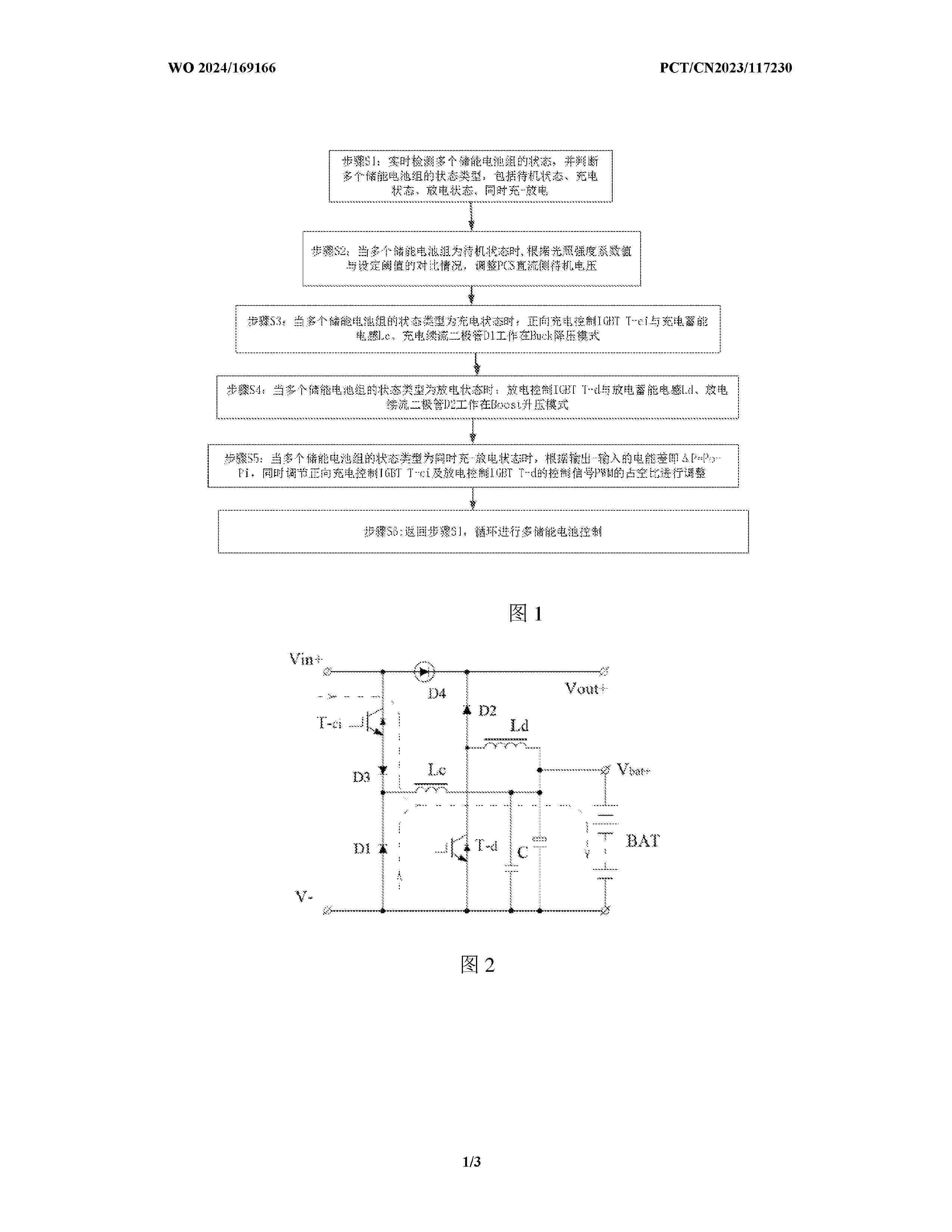
An illumination-based control method for a battery pack in a hybrid energy storage state, comprising: step S1: detecting the states of a plurality of energy storage battery packs in real time, and when in a standby state, entering step S2, when in a charging state, entering step S3, when in a discharging state, entering step S4, or when in a simultaneous charging-discharging state, entering step S5; step S2: when in the standby state, measuring the illumination condition, and adjusting circuit parameters according to a result obtained by comparing a current illumination coefficient value with a set threshold value; step S3: when in the charging state, an energy storage battery pack working in a Buck mode; step S4, when in the discharging state, an energy storage battery pack working in a Boost mode; step S5, when in the charging-discharging state, performing adjustment according to an output-input electric energy difference; and step S6, returning to the step S1, so as to circularly control the plurality of energy storage batteries. Thus, the new energy power generation control method can enable the battery packs in hybrid energy storage to safely, stably, quickly and efficiently collect and store new energies.
Resumen de: US2024282872A1
A method for producing at least one photovoltaic cell for converting electromagnetic radiation into electrical energy, having the method steps of: A. providing a superstrate in the form of a semiconductor substrate; B. applying photovoltaic cell semiconductor layers for forming at least one photovoltaic cell to a rear face of the superstrate indirectly or directly, and the photovoltaic cell semiconductor layers have at least one absorber layer formed from a direct semiconductor. The superstrate is in the form of a current conducting layer having a thickness greater than 10 μm and, in method step B, the photovoltaic cell semiconductor layers are formed with an electrically conductive connection to the current conducting layer and wherein the band gap of the current conducting layer is larger by at least 50 meV than the band gap of the absorber layer.
Resumen de: US2024282868A1
A device for improving the ohmic contact between a front side contact and a doped layer of a wafer solar cell that includes a front side, a rear side and a rear side contact. The front side and/or the rear side contact are strips or grids. The device includes: a contacting unit for contacting the front or rear side contact; a further contacting unit for contacting the other contact; a voltage source having one pole for connection to the contact unit and another pole for connection to the further contacting unit; and a point light source to illuminate the front or rear side. The further contacting unit includes: an optically transparent material, coated using an optically transparent, electrically conductive layer; or an optically transparent material having microscopically-thin wires; or an optically transparent, electrically conductive material having microscopically-thin wires; or a mesh or a network made up of microscopically-thin wires.
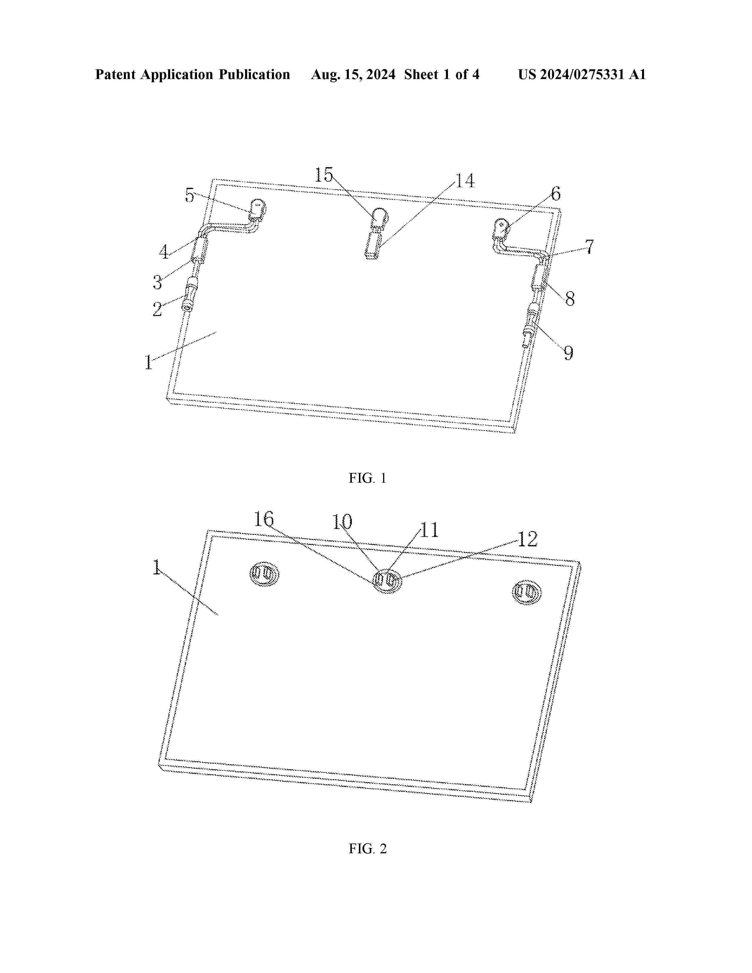
Resumen de: DE102023118883A1
Die vorliegende Erfindung offenbart einen neuen Verbinder, der ein Photovoltaikmodul, eine negative Sammelschienenbuchse, eine positive Sammelschienenbuchse, eine Bypass-Sammelschienenbuchse und eine Modulbuchse umfasst, wobei die negative Sammelschienenbuchse und die positive Sammelschienenbuchse in die Modulbuchse eingesteckt sind, die negative Sammelschienenbuchse mit einem ersten Sammelschienenkabel verbunden ist, wobei das erste Sammelschienenkabel mit einer ersten Diodenbaugruppe verbunden ist, die erste Diodenbaugruppe mit einer ersten Steckklemme verbunden ist, die erste Diodenbaugruppe an einer Seite des Photovoltaikmoduls eingerastet ist und die positive Sammelschienenbuchse mit einem zweiten Sammelschienenkabel verbunden ist. Neuer Verbinder, der in der vorliegenden Erfindung beschrieben ist, bietet eine zuverlässige Verbindung, erhöht die Kreislaufeffizienz des Moduls, optimiert die Modulstruktur, spart Installationsschritte, wobei ein Aluminiumrahmen für die Belüftung und Wärmeableitung verwendet wird, wodurch die Strombelastbarkeit des Verbinders verbessert wird, wobei die erforderliche Kabellänge entsprechend den tatsächlichen Bedürfnissen des Installationsortes bestimmt werden kann, was die Kabelkosten spart und den Energieübertragungsverlust verringert.
Resumen de: DE102023000513A1
WÜRFEL IN FORM VON RECHTECKEN ODER QUADRATEN, FARBIG ODER SCHWARZ, SIND MIT BATTERIESPEICHERN UND SCHALTELEMENTEBOX IM INNEREN DES WÜRFELS AUSGESTATTET. DER STANDFUß LÄßT SICH MIT STECKVERBINDUNGEN AM OBERTEIL DES WÜRFELS BEFESTIGEN. ER BEINHALTET DIE STECKELEMENTE FÜR DIE AKKUS. SOLARPANELE SIND AN MINDESTENS DREI SEITEN DES WÜRFELS ANGEORDNET.
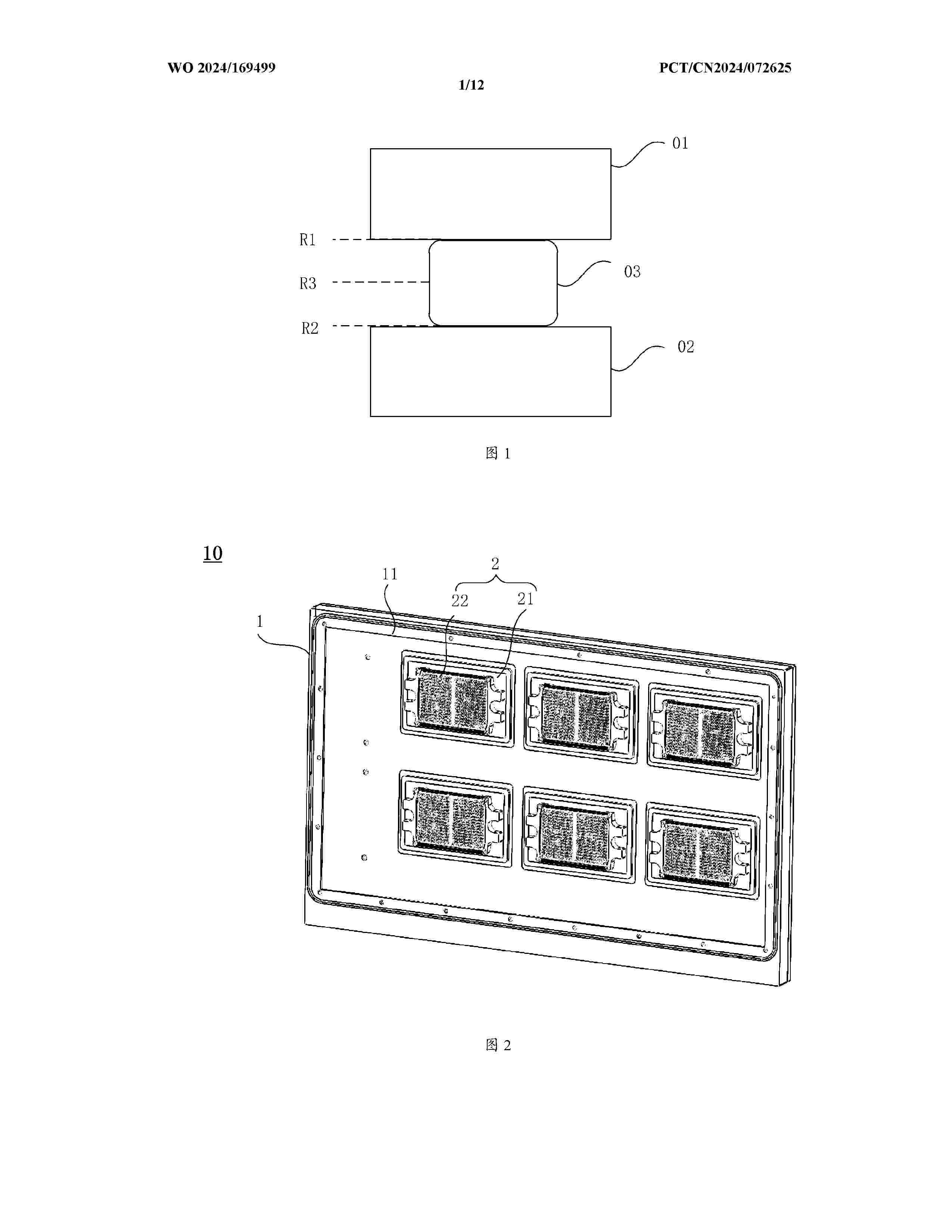
Resumen de: WO2024169499A1
The present application relates to the technical field of heat dissipation, and in particular, to a photovoltaic inverter and a power device. The photovoltaic inverter comprises a radiator and a power module. The radiator comprises a bottom shell and a top shell which are oppositely arranged, and the bottom shell and the top shell can define a heat dissipation cavity. The heat dissipation cavity is used for containing a cooling working medium. The bottom shell comprises a window, and the window runs through the bottom shell. The power module is fixed onto the surface of the bottom shell away from the heat dissipation cavity, and the orthographic projection of the power module on the bottom shell overlaps the orthographic projection of the window on the bottom shell, so that the power module can make contact with the cooling working medium in the heat dissipation cavity by means of the window. The power module of the photovoltaic inverter can make contact with the cooling working medium in the heat dissipation cavity of the radiator by means of the window, a heat conduction medium is omitted, direct-cooling heat dissipation of the power module can be achieved, and the heat dissipation efficiency is thus improved.
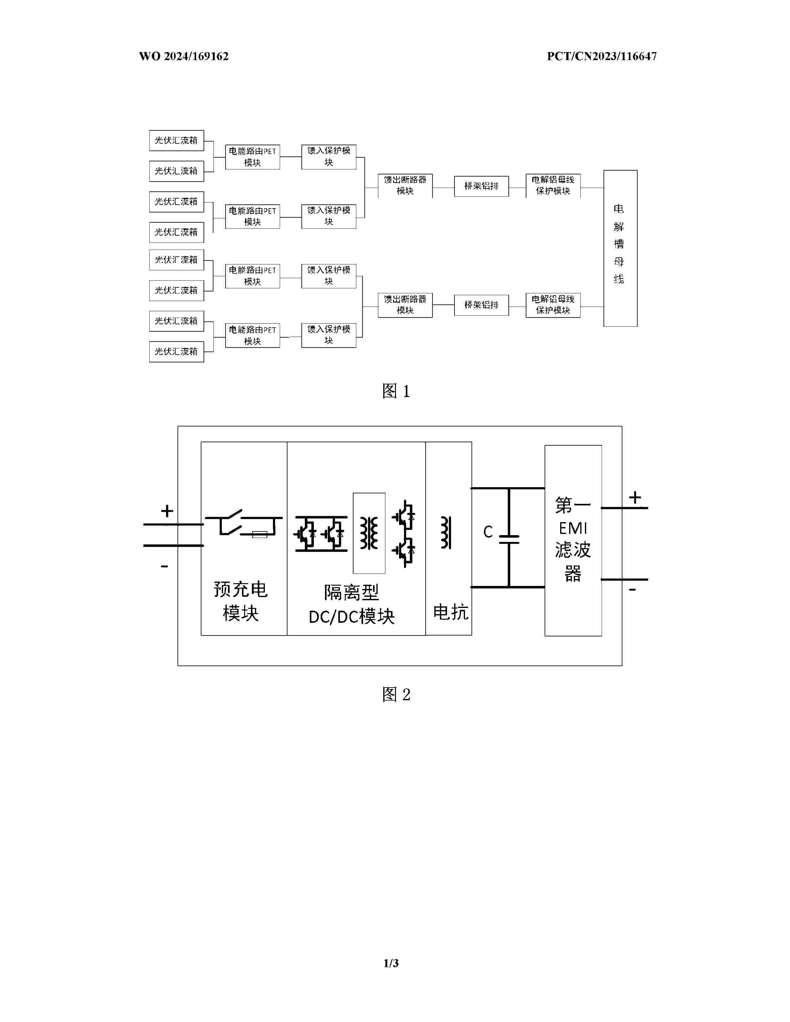
Resumen de: WO2024169162A1
The present invention relates to the technical field of aluminum electrolytic tank power supply. Provided is a power supply apparatus in which a distributed photovoltaic direct current is connected to a direct-current bus of an aluminum electrolytic tank, which power supply apparatus aims to directly supply a direct current to the aluminum electrolytic tank by means of photovoltaic power generation. The power supply apparatus comprises multiple photovoltaic strings, eight photovoltaic combiner boxes, four electric energy router PET modules, four feed-in protection modules, two feed-out circuit breaker modules and two electrolytic aluminum bus protection modules, wherein the multiple photovoltaic strings are gathered and connected to the photovoltaic combiner boxes, and every two photovoltaic combiner boxes are jointly connected to one electric energy router PET module; each electric energy router PET module is respectively connected to one feed-in protection module; every two feed-in protection modules are jointly connected to one feed-out circuit breaker module; the two feed-out circuit breaker modules are respectively connected to one electrolytic aluminum bus protection module by means of one bridge aluminum bar; and the electrolytic aluminum bus protection modules are directly connected to an electrolytic tank bus. The present invention has the advantages of direct photovoltaic power supply, stability, and low energy consumption.
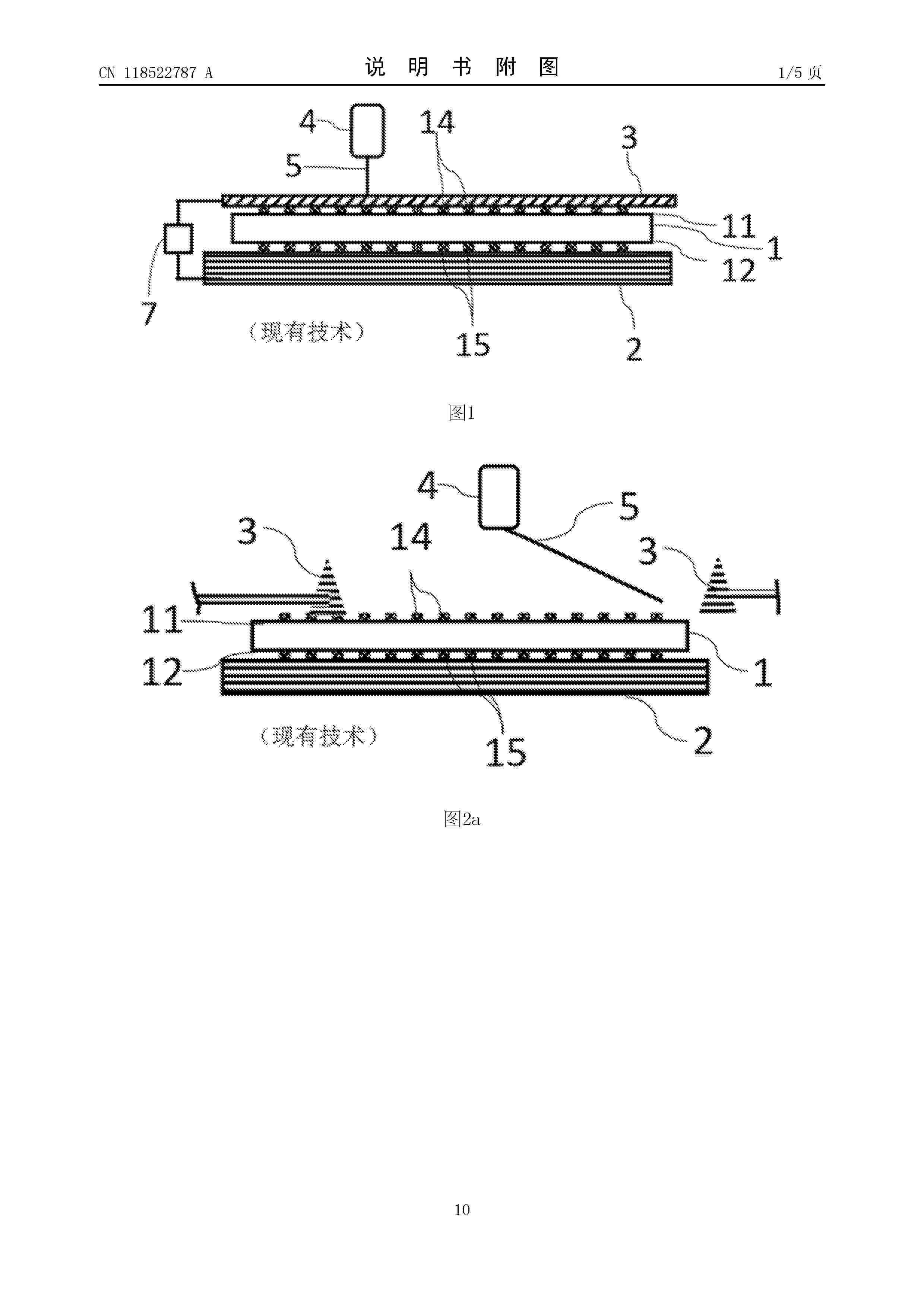
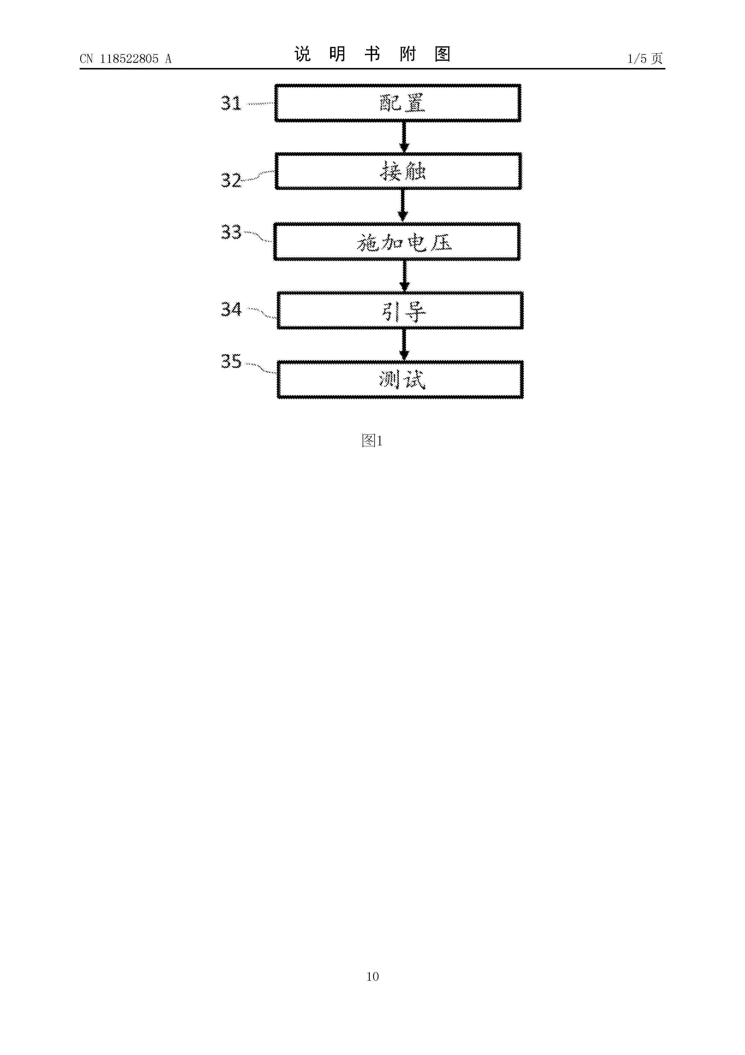
Resumen de: DE102023104175A1
Die Erfindung betrifft ein Verfahren zur Verbesserung eines Kontaktwiderstands einer Mehrfach-Solarzelle (1) mit einer Vorderseite (100) und einer Rückseite (101) und mehreren Teilzellen (2,3), wobei das Verfahren aufweist:a) Bereitstellen (50) der Mehrfach-Solarzelle (1) mit einem Vorderseiten-Kontakt (11) und einem Rückseiten-Kontakt (25), wobei der Vorderseiten-Kontakt (11) und/oder der Rückseiten-Kontakt (25) gitterförmig, streifenförmig oder transparent ausgebildet ist oder sind,b) elektrisches Kontaktieren (32) eines Bereichs des Rückseiten-Kontakts (25) mit einer mit einem Pol einer Spannungsquelle (9) elektrisch verbundenen Kontaktiereinrichtung (4) und des Vorderseiten-Kontakt (11) oder eines weiteren, von dem Bereich elektrisch isolierten Bereich des Rückseiten-Kontakts (25) mit einer weiteren, mit dem anderen Pol der Spannungsquelle (9) elektrisch verbundenen Kontaktiereinrichtung (4),c) Anlegen (52) einer entgegen der Vorwärtsrichtung der Mehrfach-Solarzelle (1) gerichteten Spannung mittels der Spannungsquelle (9) an dem Vorderseiten-Kontakt (11) und dem Rückseiten-Kontakt (25), wobei die angelegte Spannung betragsmäßig geringer ist als die Durchbruchsspannung der Mehrfach-Solarzelle (1),d) Führen (53) mindestens einer Punktlichtquelle (5) über die Vorderseite (100) und/oder die Rückseite (101) der Mehrfach-Solarzelle (1) während des Anliegens der Spannung, wobei dabei ein oder mehrere Ausschnitte (6) eines Teilbereichs der Vorder- oder Rückseite (
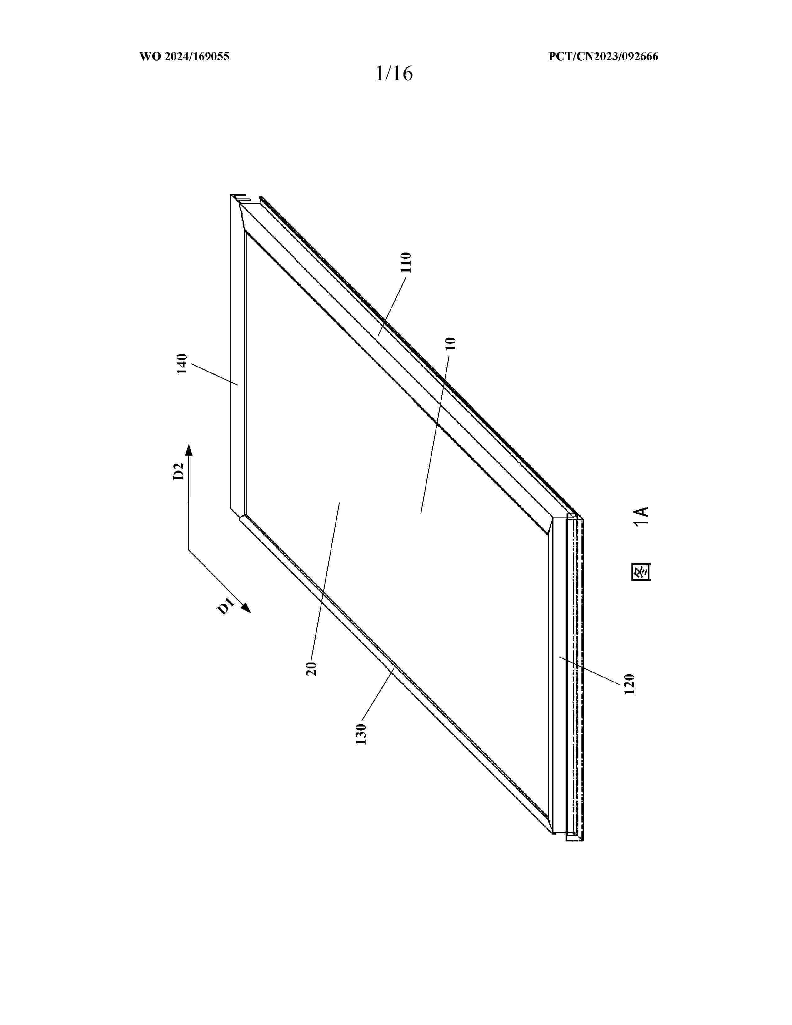
Resumen de: WO2024169055A1
Provided in the present application are a photovoltaic profile, a photovoltaic roof tile assembly and a photovoltaic roof mounting system. The photovoltaic profile comprises: a first frame side, a second frame side, a third frame side and a fourth frame side, assembling corner parts of said frame sides being sequentially connected, the assembling angle of first assembling corner parts and the assembling angle of third assembling corner parts being both greater than the assembling angle of second assembling corner parts and the assembling angle of the fourth assembling corner parts, and a first drainage channel of the first frame side being communicated with a second drainage channel of the second frame side. The photovoltaic profile, the photovoltaic roof tile assembly and the photovoltaic roof mounting system of the present application can effectively discharge rainwater through the drainage channels communicated with each other in the photovoltaic frame sides, so as to prevent the rainwater from damaging the photovoltaic profile and the photovoltaic assembly, thus improving the reliability of the overall waterproof performance of roofs. In addition, the sequential connection of the photovoltaic frame sides by means of the assembling corner parts and the special design of the assembling angles enable the photovoltaic profile of the present application to have the advantages of simple structure and easy processing.
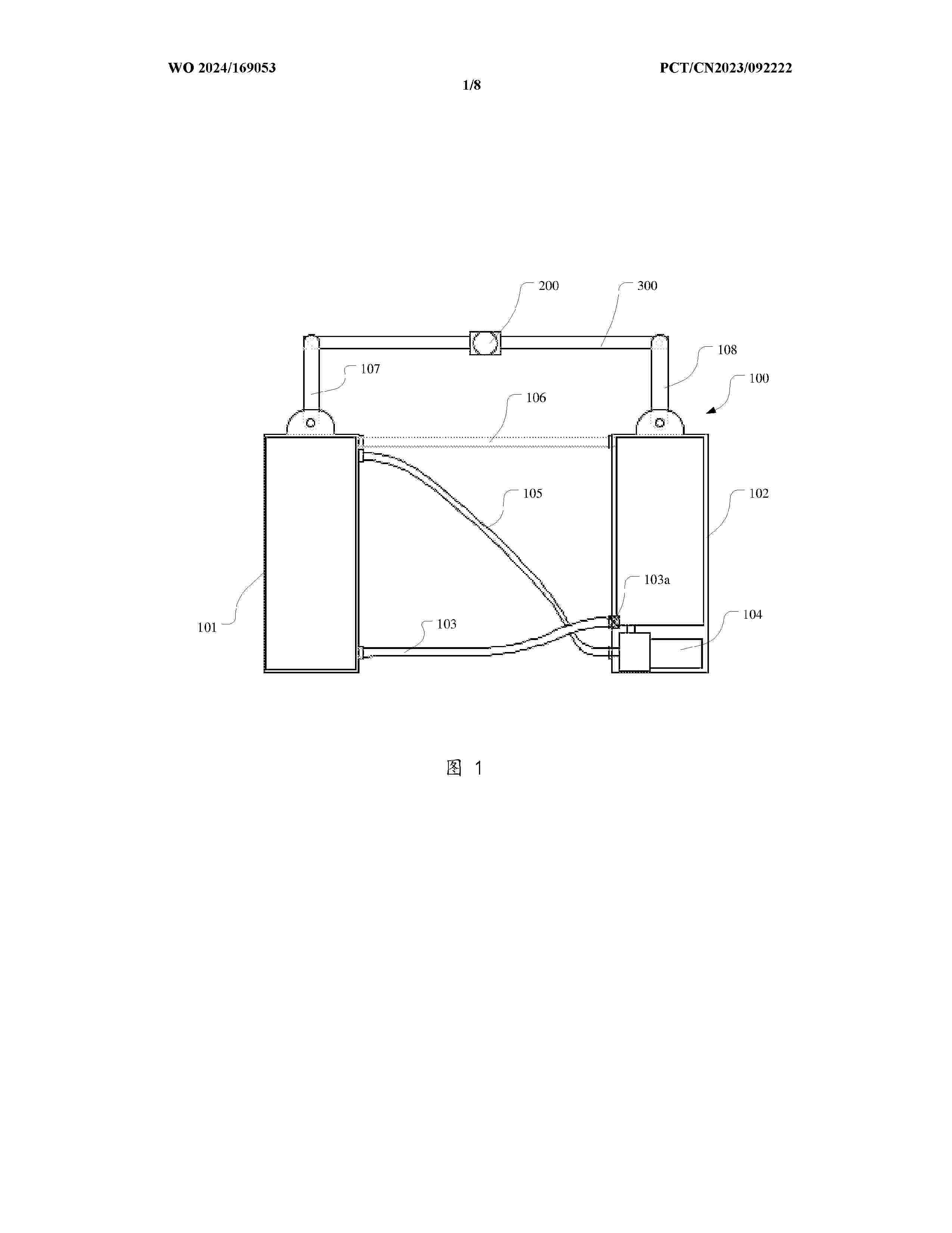
Resumen de: WO2024169053A1
The present application discloses a driving unit, an angle-adjustable supporting device, and a photovoltaic system. The driving unit comprises: rotating arms respectively provided on two sides of a rotating shaft; a first buoyancy unit provided with an inner cavity for containing liquid, wherein the first buoyancy unit is connected to the rotating arm on one side of the rotating shaft; and a second buoyancy unit provided with an inner cavity for containing liquid, wherein the second buoyancy unit is connected to the rotating arm on the other side of the rotating shaft and is communicated with the first buoyancy unit. According to the present application, the amounts of liquid in the first buoyancy unit and the second buoyancy unit are adjusted, so that the height of the first buoyancy unit and the height of the second buoyancy unit above the water surface are different, so as to adjust the rotation of the rotating shaft; and a photovoltaic module is driven by the rotating shaft to correspondingly deflect, so that angle adjustment of the photovoltaic module is realized. The present application avoids the problem of power consumption caused by the use of a motor to drive a rotating shaft to rotate.
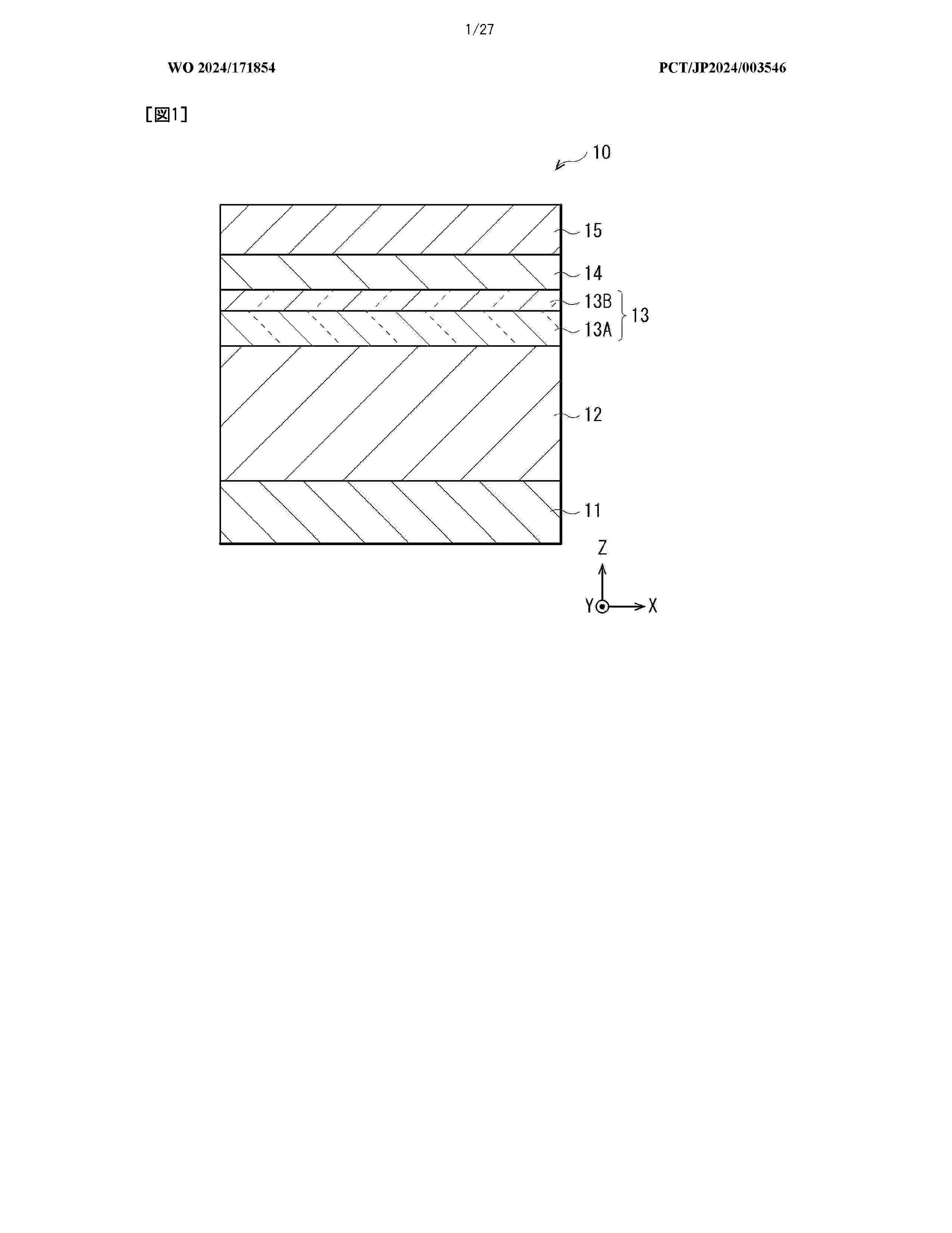
Resumen de: WO2024171854A1
A photoelectric conversion element (10) according to one embodiment of the present disclosure comprises: a first electrode (11); a second electrode (15) disposed opposite the first electrode (11); a photoelectric conversion layer (12) provided between the first electrode (11) and the second electrode (15); a work function adjustment layer (14) provided between the photoelectric conversion layer (12) and the second electrode (15) and having a work function greater than a work function of the first electrode (11); a first electron blocking layer (13A) provided between the photoelectric conversion layer (12) and the work function adjustment layer (14); and a second electron blocking layer (13B) provided between the first electron blocking layer (13A) and the work function adjustment layer (14), and having a HOMO level which is deeper than the HOMO level of the first electron blocking layer (13A) and is deeper than the LUMO level of the work function adjustment layer (14).
Resumen de: US2024280214A1
A frame enhancer may include a body, a first extension extending from the body and including a first notch, a second extension extending from the body, and a third extension extending from the body and including a second notch. The first extension and the second extension may define a first slot. The second extension and the third extension define a second slot. The first slot may be configured to receive a first side of a support arm, and the second slot may be configured to receive a second side of the support arm. The first notch may be configured to lock the first side of the support arm in the first slot, and the second notch may be configured to lock the second side of the support arm in the second slot. At least a portion of the first and third extensions may be configured to support a flange.
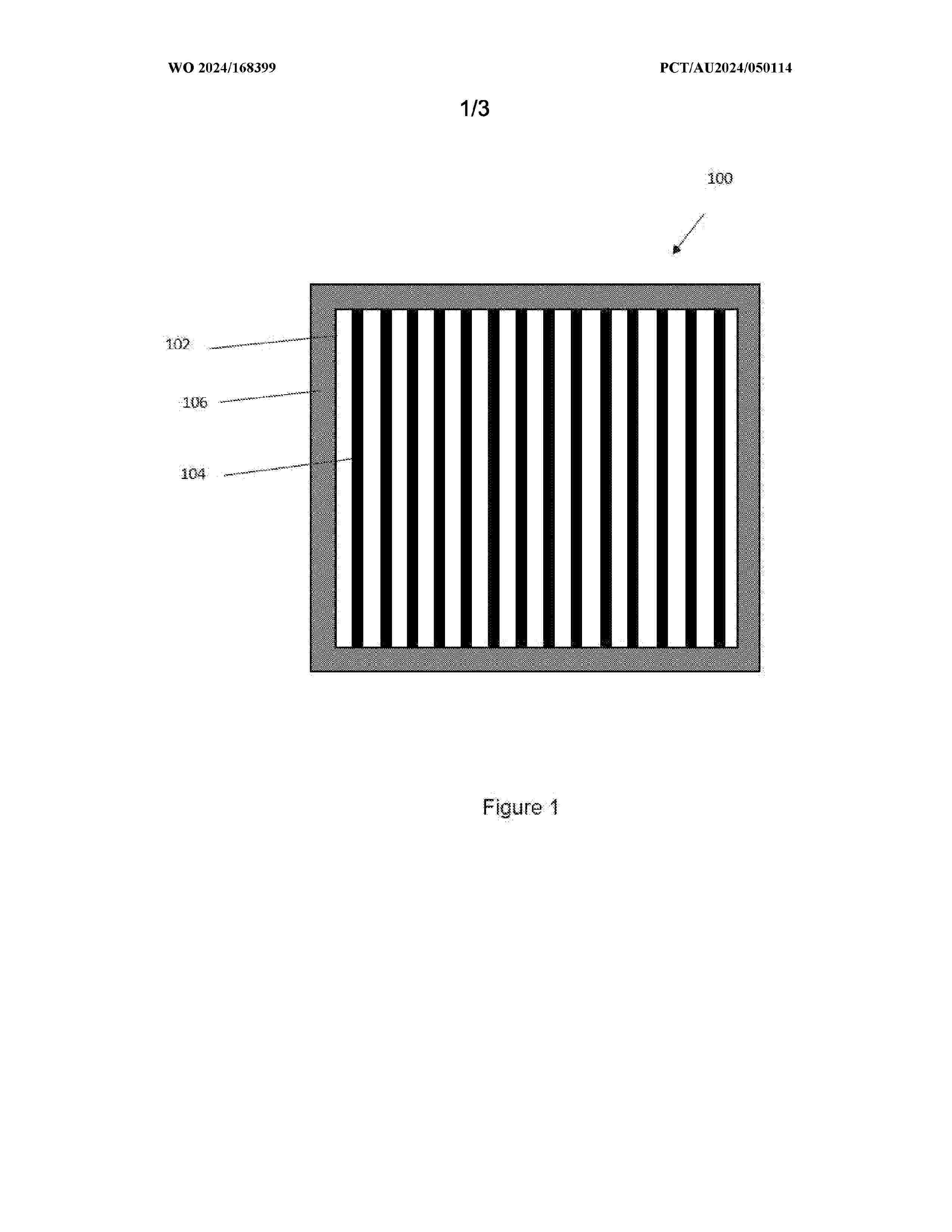
Resumen de: WO2024168399A1
The present disclosure provides a window for a building or structure. The window comprises first and second panels which have major surfaces and are at least largely transmissive for visible light. The second panel has major surfaces which are smaller than the major surfaces of the first panel. Further, the second panel is positioned parallel to the first panel such that the second panel is within a projection of the circumference of the first panel in a direction along the surface normal of the first panel. The first and second panels are laminated together. The first and second panels are arranged such that the first panel has a border region which extend beyond the circumference of the second panel and the laminated first and second panels can be supported at the border region of the first panel.
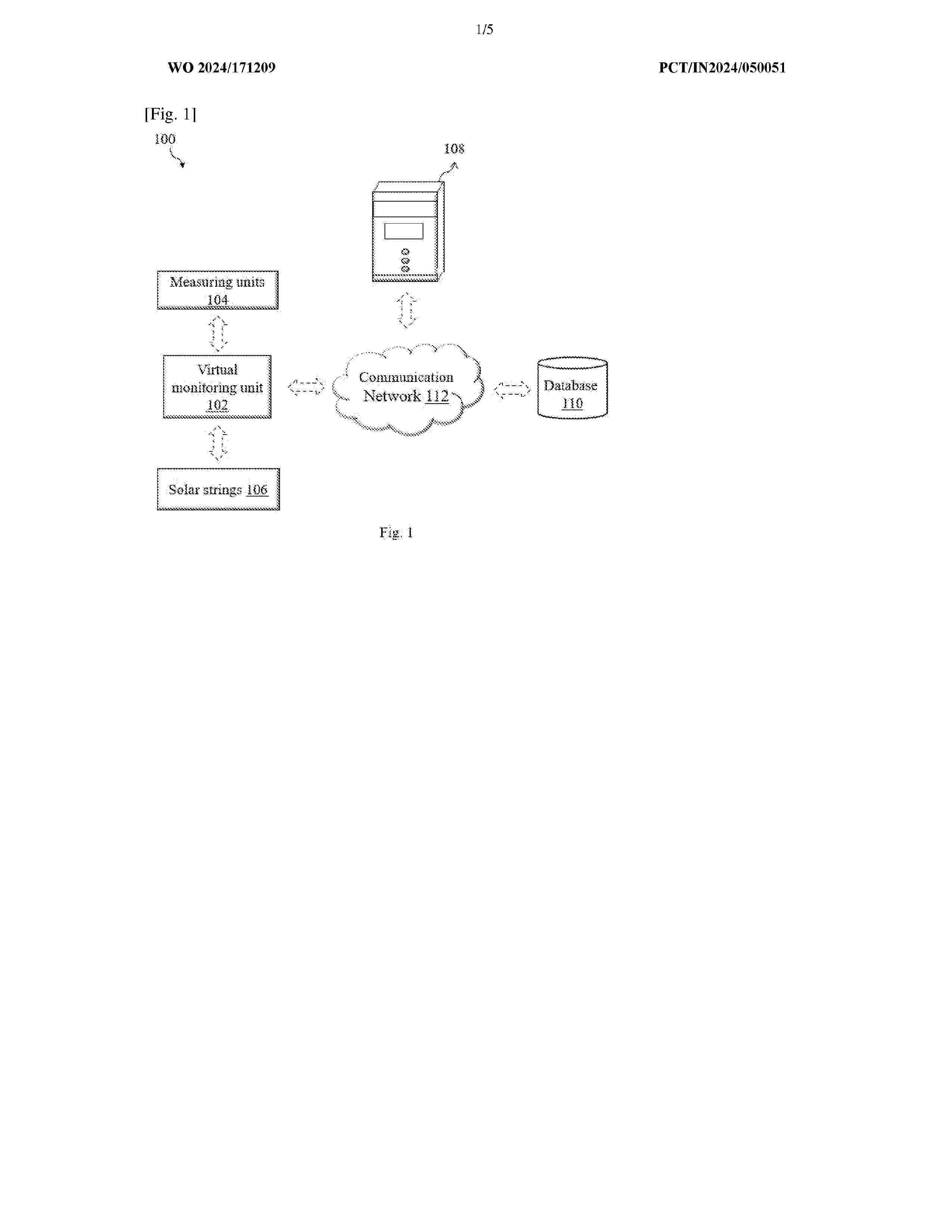
Resumen de: WO2024171209A1
The present invention discloses a digital twin system (100) and method (500) for solar power plants. The digital twin system (100) comprises a plurality of measuring units (104) configured to measure one or more parameters of a solar power plant. The plurality of solar strings (106) configured to provide one or more inputs of a solar power plant to a virtual monitoring unit (102). The virtual monitoring unit (102) configured to obtain the one or more inputs from the plurality of measuring units (104) and the plurality of solar strings (106), wherein the virtual monitoring unit (102) predicts probability of at least one loss factor and provide remedial actions for improved performance of the solar plant. The virtual monitoring unit (102) mainly comprises a data collection module (202), an equipment monitoring module (204), an asset managing module (206), and a controller (208).
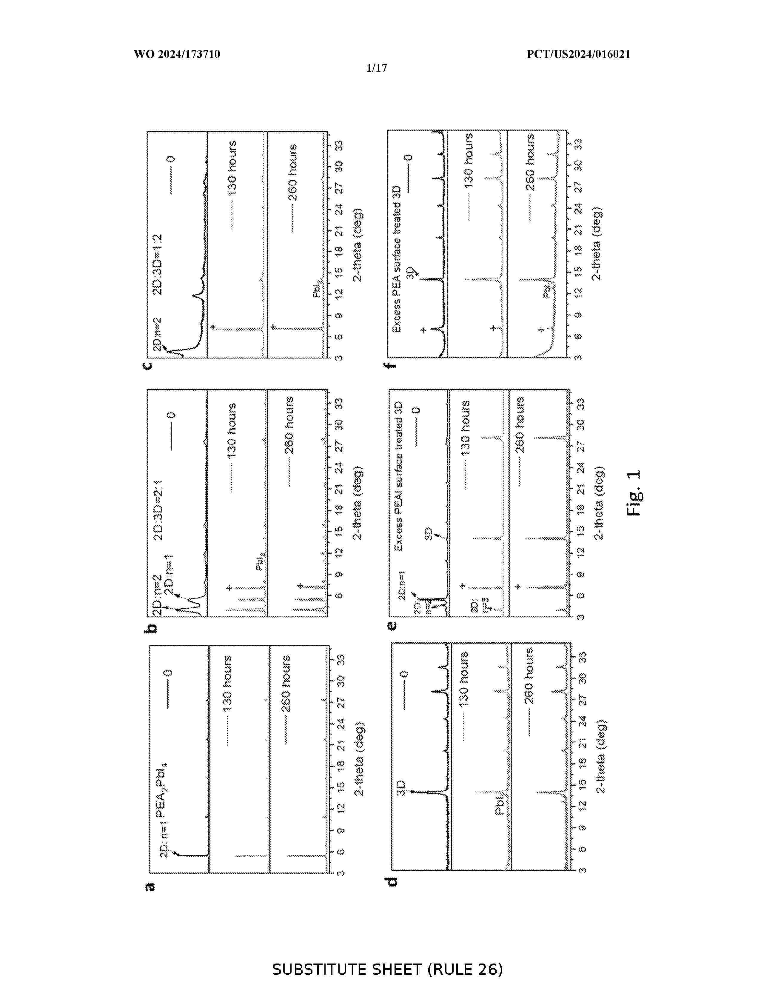
Resumen de: WO2024173710A1
Described herein are perovskite films comprising a composition of Formula I (ABXs) and a compound of Formula II wherein A, B, X, D, R1 and R2 are as defined herein. Further described are precursor perovskite solutions, methods for preparing the perovskite films, and use of the films in solar cells. As shown herein, solar cells fabricated using the perovskite films containing ammonium cations of Formula II as additives achieve enhanced efficiency and much improved thermal stability.
Resumen de: WO2024172683A1
The invention relates to electrical engineering and can be used for efficiently extracting power from solar panels and converting and transmitting the energy obtained to a commercial network and to a consumer load. A photovoltaic panel-based device for uninterrupted electric power supply consists of a unit of solar panels, a unit of current and voltage sensors for the unit of solar panels, a DC/DC voltage converter, a DC bus, a reversible inverter, a unit of converter output current and voltage sensors, a DC/DC voltage converter control unit, an inverter control unit, a microcontroller for control and switching, a unit of DC bus current and voltage sensors, an LC filter, an RFI filter, a unit of load current and voltage sensors, and a voltage pulse unit mounted between the unit of solar panels and the DC/DC voltage converter. The DC/DC voltage converter control unit is configured to perform the additional function of controlling the voltage pulse unit. The invention makes it possible to increase the energy obtained from the unit of solar panels, increase the reliability of the electric power supply to an electrical energy consumer, and increase the flexibility and functionality of the energy system of the consumer.
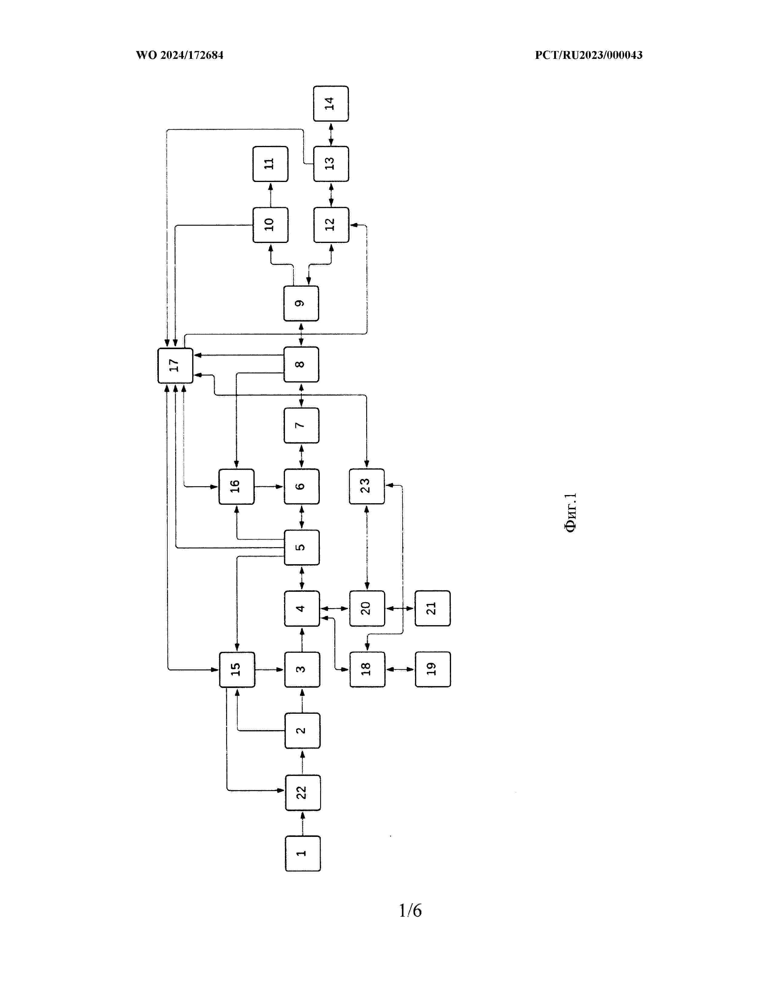
Resumen de: WO2024172684A1
The utility model relates to conversion technology, and can be used for efficiently extracting power from solar panels and converting and transmitting the energy obtained to a commercial network and to a consumer load. A solar cell-based power supply device consists of the following interconnected components: a unit of solar panels, a unit of current and voltage sensors for the unit of solar panels, a DC/DC voltage converter, a DC bus, an inverter, a unit of converter output current and voltage sensors, a DC/DC voltage converter control unit, an inverter control unit, a microcontroller for control and switching, a unit of DC bus current and voltage sensors, an LC filter and an RFI filter, and a unit of load current and voltage sensors, wherein the device further includes a voltage pulse unit mounted between a solar panel and the DC/DC voltage converter. The technical result of the proposed device is an increase in the energy obtained from the unit of solar panels.
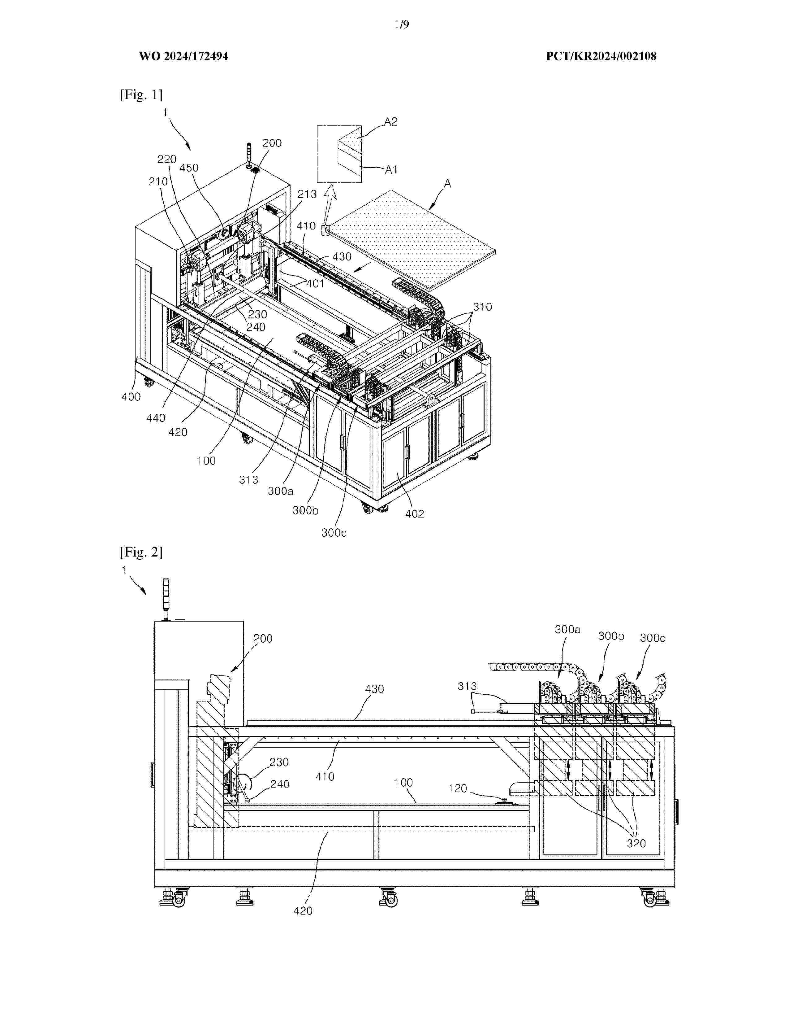
Resumen de: WO2024172494A1
The solar panel disassembling apparatus is designed for separating the glass plate and stacked film of solar panels. It features a supporting plate that holds the panel, a moving scraper module with a blade attached to an elevator for vertical movement, which scrapes the film off the glass. Ahead of this, a moving pressing module with a pressing unit, also attached to an elevator for height adjustment, aligns and presses the film for efficient separation. A bending guide plate positioned above the blade rolls and secures the removed film. This compact and efficient design streamlines the disassembly process, making it ideal for recycling and repurposing solar panel materials.
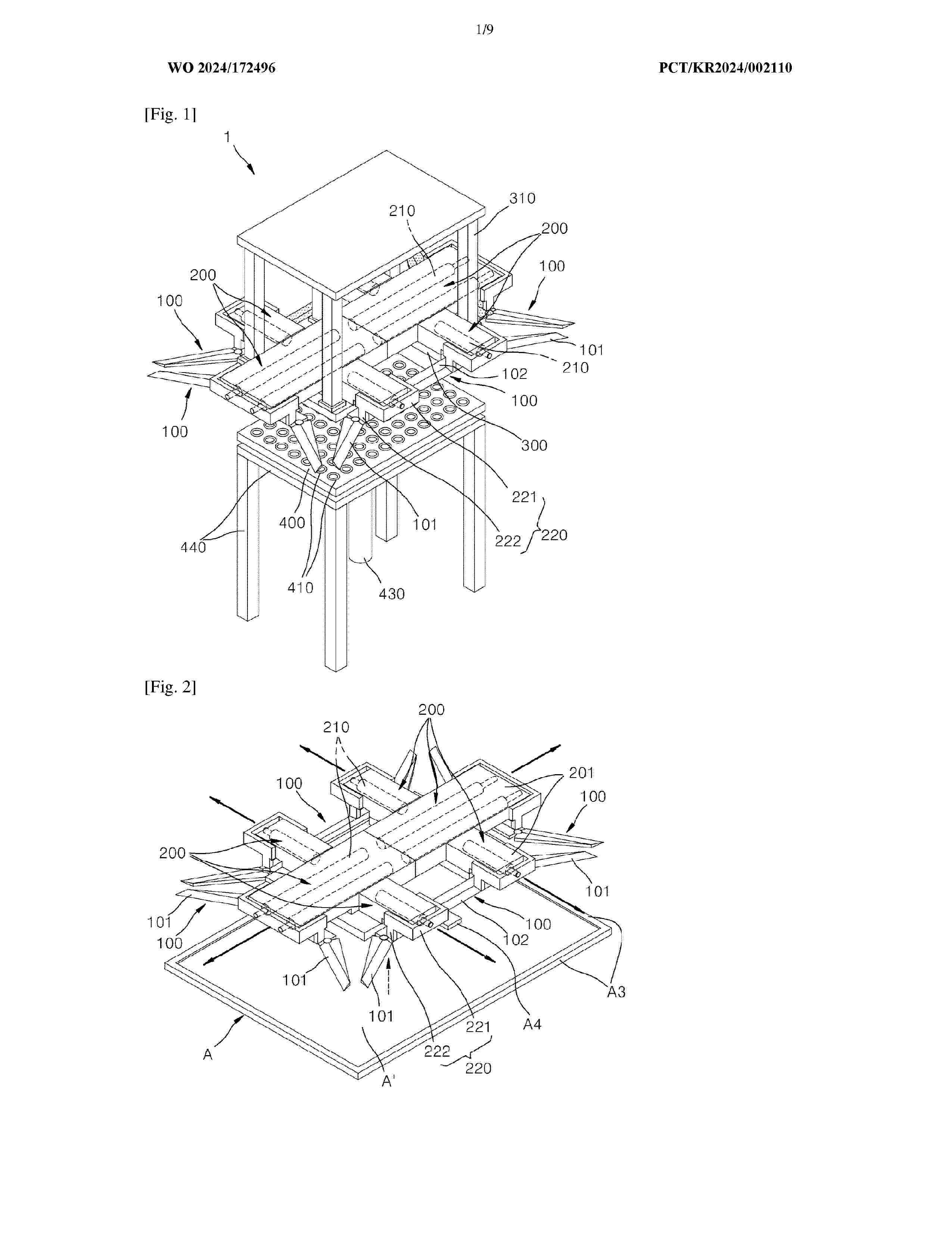
Resumen de: WO2024172496A1
The solar module exterior disassembling apparatus is designed for efficiently removing the frame and junction box from solar modules. It features a positioning plate that supports the module from below and adjusts vertically. The apparatus employs foldable variable frame separation blades that transition between an inner position, within the module frame, and an outer position, facilitating frame detachment. These blades, capable of folding and unfolding, ensure close contact with the frame sides during operation. A pressing actuator, equipped with multiple pressing cylinders, exerts outward pressure to disassemble the module by advancing the separation blades. This system allows for precise and controlled removal of solar module exteriors, making it ideal for recycling and maintenance processes, enhancing the sustainability and efficiency of solar module management.
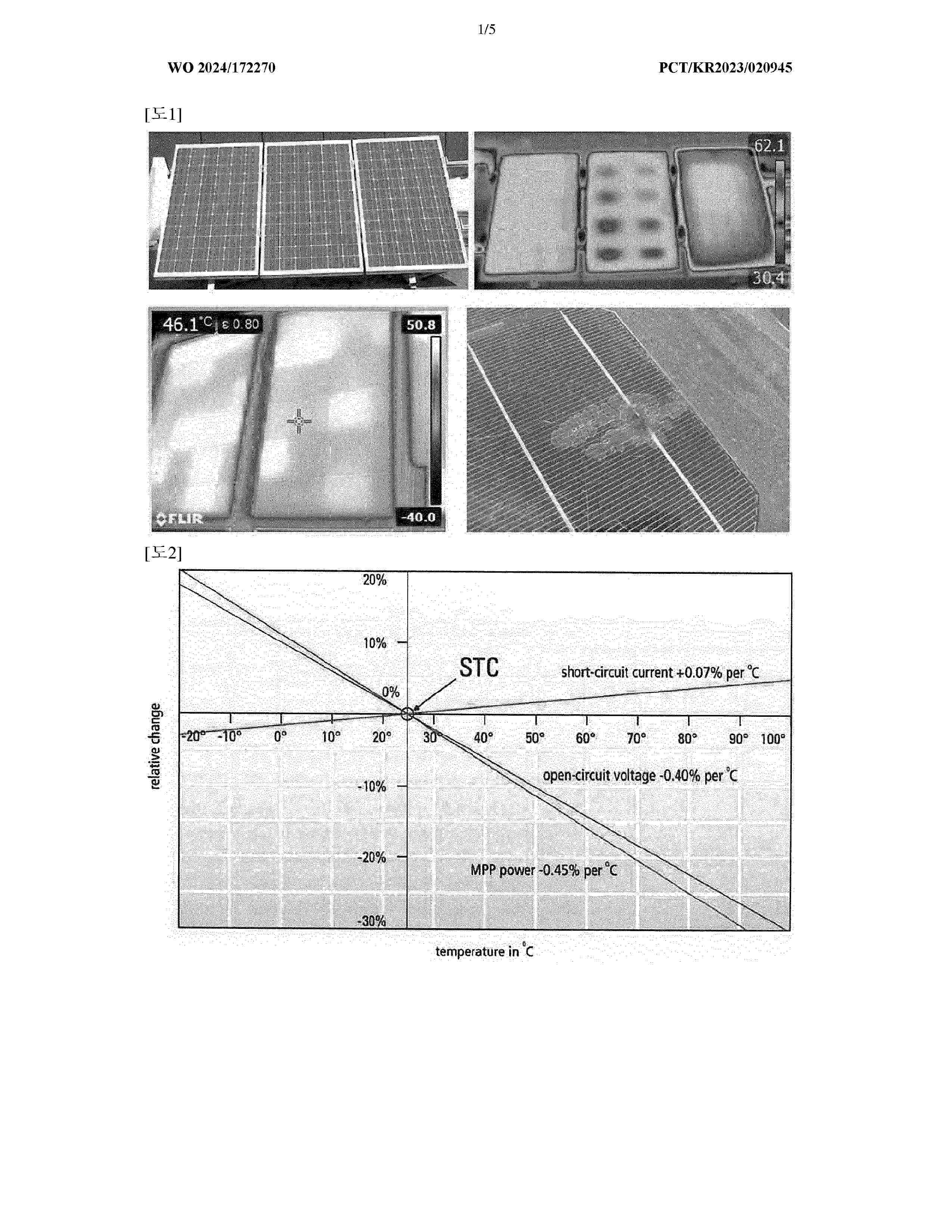
Resumen de: WO2024172270A1
The present invention relates to a thermal fluid hybrid power generation system and hybrid power generation method using the energy combination of a flow battery and a solar module and, more specifically, to a thermal fluid hybrid power generation system using the energy combination of a flow battery and a solar module, comprising: a flow battery having an electrolyte tank; solar module cells for generating electricity by means of sunlight or solar heat; and a cooling channel which is installed on one side of the solar module cells and into which an electrolyte is introduced to cool the solar module cells.
Nº publicación: US2024282876A1 22/08/2024
Solicitante:
MAXEON SOLAR PTE LTD [SG]
Maxeon Solar Pte. Ltd
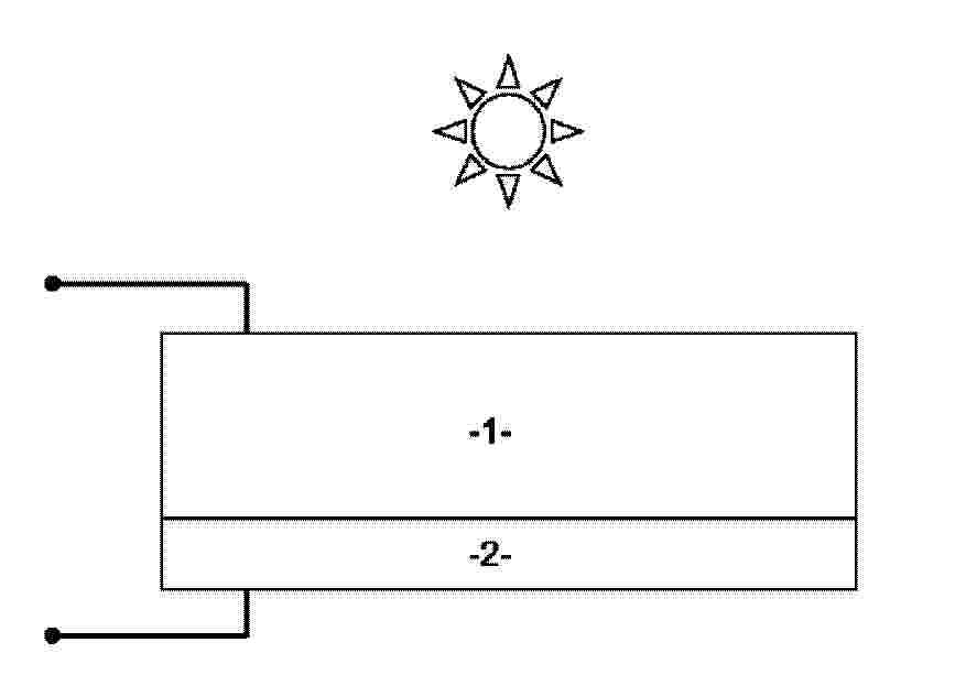
Resumen de: US2024282876A1
A string of solar cells is disclosed. The sides of the solar cells have a corrugated shape which forms an opening when the solar cells are arranged in a shingled manner. The solar cells are electrically connected in series by a ribbon that passes through the opening. A wire mesh used to decrease solar cell resistance is also disclosed.
 BOPI
BOPI
 Sede Electrónica